

Westell CSI DSP85 PSS8 Users Manual
CSI-DSP85-PSS8
Installation Manual
CSI-DSP85-C
Installation Manual


T able of Contents
Application.......................................................................................................................................................4
Safety Guidelines ............................................................................................................................................4
Document Purpose / Intended Users..............................................................................................................4
Product Registration Information ...................................................................................................................4
Important Safety Information ......................................................................................................................... 5
Product Introduction........................................................................................................................................5
T erms used in this manual..............................................................................................................................5
Band Plan and Naming Convention ..............................................................................................................6
Functional Overview .......................................................................................................................................7
LED Indicators ..................................................................................................................................................7
Local Communication Interface Ports ...........................................................................................................8
Approximate Signal Strengths of Bargraph Display ....................................................................................8
EIA232 Pin Specifications ............................................................................................................................... 8
USB Interface...................................................................................................................................................8
Ethernet ............................................................................................................................................................8
Monitoring & Alarms........................................................................................................................................9
System Set-Up Considerations ....................................................................................................................... 9
Selection of external attenuators to be used in line with the CSI-DSP85 Antenna Port(s): ...................... 9
Attenuator Selection Guidelines: ................................................................................................................. 10
Wall Mounting the CSI-DSP85-PSS8, Digital Repeater ..............................................................................11
Optional Accessories ..................................................................................................................................... 12
Important Installation Notes..........................................................................................................................12
Circuit Operational Description .................................................................................................................... 12
Functional Block Diagram ............................................................................................................................ 13
AC Power Specifications ..............................................................................................................................14
Environmental Requirements....................................................................................................................... 14
Mechanical Specifications............................................................................................................................ 14
Operating Power Parameters ....................................................................................................................... 15
Mechanical Drawing ..................................................................................................................................... 16
System Status: ............................................................................................................................................... 17
Web based GUI Session................................................................................................................................ 17
Local Network:............................................................................................................................................... 18
Program a Filter: ........................................................................................................................................... 19
RF Configuration: .......................................................................................................................................... 19
Remote Network: ........................................................................................................................................... 20
SNMP Configuration:..................................................................................................................................... 20
Install & Upload: ........................................................................................................................................... 21
System Health:............................................................................................................................................... 21
Reboot: ........................................................................................................................................................... 22
Alarm Configuration:..................................................................................................................................... 22
Log Configuration:.........................................................................................................................................23
T ext Menu Interface (Local Access) ............................................................................................................. 23
Terminal Emulation Program ....................................................................................................................... 24
Terminal Program Set-Up ............................................................................................................................. 25
TMI Login ....................................................................................................................................................... 26
T elnet Session (Remote Access)...................................................................................................................28
Modem Interface (Remote Access with login)............................................................................................. 30
Additional Tips............................................................................................................................................... 31
Warranty Information .................................................................................................................................... 34
Industry Certifications/Registration Numbers: ............................................................................................. 34
Index .............................................................................................................................................................. 35

Product Registration Information
The serial number may be found on the label on the bottom panel near the power
connectors. Note this number below. Retain this manual, along with proof of purchase, to serve as a permanent record of your purchase.
MODEL NUMBER SERIAL NUMBER DA TE OF PURCHASE
POINT OF SALE COMP ANY
DISCLAIMER: All information and statements contained herein are accurate to the best of the
knowledge of Cellular Specialties, Inc. (CSI), but Cellular Specialties makes no warranty with
respect thereto, including without limitation any results that may be obtained from the products
described herein or the infringement by such products of any proprietary rights of any persons.
Use or application of such information or statements is at the users sole risk, without any liability
on the part of Cellular Specialties, Inc. Nothing herein shall be construed as licence or recommendation for use, which infringes upon any proprietary rights of any person. Product material and
specifications are subject to change without notice. Cellular Specialties’ standard terms of sale
and the specific terms of any particular sale apply.
Document Purpose / Intended Users
The purpose of this document is to provide a step-by-step procedure to help the experienced
technician/engineer install and commission an in-building wireless enhancement repeater system
using CSI’s DSP85-PSS8 Digital Repeater. Following the procedures outlined will minimize risks
associated with modifying a live system and prevent service interruptions. This document assumes
the technician/engineer understands the basic principles and functionality involved with Repeater
and in-building systems. It is geared to the practical concerns of the installer.
Application
This guide should be applied whenever a need exists to add Digital Repeater capability to an
existing system or when this capability is being included with a new installation.
Safety Guidelines
The general safety information in this guideline applies to both operating and service personnel.
Specific warnings and cautions will be found in other parts of this manual where they apply, but
may not appear in this summary. Failure to comply with these precautions or specific warnings
elsewhere in the manual violates safety standards of design, manufacture, and intended use of
equipment. Cellular Specialties, Inc. assumes no liability for the customer’s failure to comply with
these requirements:
Grounding
This Digital Repeater system is designed to operate from 100-240 VAC and should always
be operated with the ground wire properly connected. Do not remove or otherwise alter the
grounding lug on the power cord.
Explosive Atmospheres
To avoid explosion or fire, do not operate this product in the presence of flammable
gases or fumes.
Lightning Danger
Do not install or make adjustments to this unit during an electrical storm. Use of a suitable
lightning arrester, such as CSI’s model number CSI-CAP, is very strongly recommended.
No User Serviceable Parts Inside
HAZARDOUS VOLTAGES ARE PRESENT WHEN THE COVER IS REMOVED. Opening the
chassis will void your warranty. If you suspect a malfunction with this product, call your dealer or
the Cellular Specialties Support Line at: (603) 626-6677, Toll Free (USA) 1-877-844-4274.
-4-

Important Safety Information
Antennas used for the purpose of radiating signals indoors are limited to a maximum gain of 3 dBi. The outdoor antenna used
for the purpose of communicating to the wireless infrastructure is limited to 14dBi gain, or any combination of gain and loss
that equates to 14dB at input. Each antenna must be positioned to observe minimum separation requirements from all users
and bystanders. The following guidelines should be used when considering separation distances.
INDOOR antennas must be placed such that, under normal conditions, personnel cannot come within 20 cm (~8.0 in.) from
any inside antenna. Adhering to this minimum separation will ensure that the employee or bystander cannot exceed RF
exposures beyond the maximum permissible limit as defined by section 1.1310 i.e. limits for General Population/Uncontrolled
Exposure.
OUTDOOR antenna must be positioned such that, under normal conditions, personnel cannot approach closer than 120 cm.
(~4 ft.). A directional antenna having a maximum gain of 14 dBi is used, precautions should be taken to prevent personnel
from routinely passing through the main radiation beam at a distance closer than specified.
T erms used in this manual
AGC= Automatic Gain Control ERP= Effective Radiated Power
APC= Automatic Power Control FPGA= Field Programmable Gate Array
AUI= Attachment Unit Interface LED= Light Emitting Diode
CPU= Central Processing Unit OIP3= Third-Order Intercept Point
CSI= Cellular Specialties, Inc. RF= Radio Frequency
DAS= Distributed Antenna System SBC= Single board Computer
DHCP= Dynamic Host Configuration SNMP= Simple Network Management Protocol
Protocol TMI= Text Menu Interface
DSP= Digital Signal Processing USB = Universal Serial Bus
EEPROM= Electrically Erasable UHCI = Universal Host Controller Interface
Programmable read only Memory
Product Introduction
Cellular Specialties, Inc. (CSI) developed the DSP85 digital repeater for use within enclosed structures where signal from local dispatch
sites is insufficient to operate on scene communication equipment. Adequate signal must be available outside the structure as a prerequisite to achieving in-building coverage. The Digital Repeater is connected to an external antenna, usually on the roof, and to one or more
internal antennas placed strategically throughout the area where wireless service is desired.
The external antenna typically is directional, such as a “yagi”. Internal antennas are typically omnidirectional, although various other types
may be used depending on the coverage application. The CSI DSP Repeater amplifies both the “uplink” (Transceiver to tower) &
“downlink”(tower to Transceiver) signals thus facilitating communications to and from the intended wireless infrastructure.
With a maximum total of +85dB nominal gain on both the up and down links, gain can be adjusted over a range from +53.5dB to +85dB in
0.5dB steps. Control of the repeater is achieved utilizing a computer connected to comm. port 1 or 2 or via a Crossover Ethernet cable
connected to the Ethernet port. There are also LED indicators near the display to indicate ALARM status, AGC status, UL PWR, DL PWR,
OSC, SHUT DWN and a D/L SIGNAL STRENGTH bargraph.
A specific filtering process modifies each amplification chain. This process digitally converts the assigned spectrum and then applies
digital signal processing (DSP) techniques. DSP is used to create passbands that selects the RF energy passing through either the uplink
or downlink paths. After the digital processing is complete, the information is converted back to an analog signal that is applied to the
remaining stages of amplification. The resulting signals emitted by the repeater are specific to the network service providers’ requirements. If these requirements change, only the DSP configuration parameters need change in order to adapt. Configuration parameters are
created at the factory and supplied as files that may be downloaded to the repeater. The filter set configurations stored in memory
determine the unit’s adaptability to various field applications. The following pages describe the public safety band plan as well as the
convention CSI uses to identify and store the files that make up the filter set. All DSP85-PSS8 repeaters are shipped with an active filter set
that is programmed according to the ordering parties’ specifications. In most cases, the installer will not have to program a filter .
- 5 -
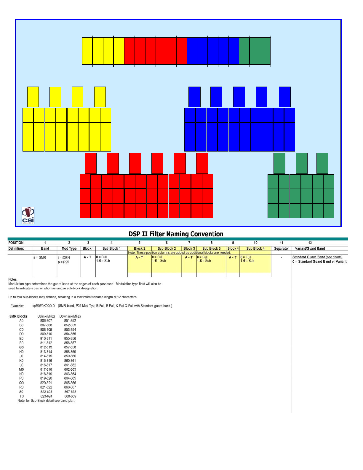
Band Plan and Naming Convention
A0
UL806-807
DL851-852
A1
A2
(.5MHz) (.5MHz)
(.5MHz)
UL806-806.5
UL806.5-807
DL851-851.5
DL851.5-852
A4
A3
(.75MHz) (.25MHz)
UL806-806.75
UL806.75-807
DL851-851 .75
DL851.75-852
A6
A5
(.25MHz) (.7 5MHz)
UL806-806.25
UL806.25-807
DL851-851 .25
DL851.25-852
UL807-808
DL852-8 53
B1
UL807-807 .5
DL852-852. 5
B3
(.75MHz)
UL807-807 .75
DL852-852. 75
B5
(.25MHz)
UL807-807 .25
DL852-852.2 5
B0
B2
(.5MHz)
UL807.5-808
DL852.5-853
B4
(.25MHz)
UL807.75-8 08
DL852.75-853
B6
(.75MHz)
UL807.25-8 08
DL852.25-853
Mobile
(MHz)
806
851
Base
(MHz)
C0
UL808-809
DL853-8 54
C1
C2
(.5MHz) (.5MHz)
UL808-808.5
UL808.5-809
DL853-853.5
DL853.5-854
C3
C4
(.25MHz)
(.75MHz)
UL808-808.7 5
UL808.75-809
DL853-853.75
DL853.75-854
C5
C6
(.75MHz)
(.25MHz)
UL808-808.2 5
UL808.25-809
DL853-853.25
DL853.25-854
E1
(.5MHz) (.5MHz)
UL810-810 .5
DL855-855 .5
E3
(.75MHz)
UL810-810 .75
DL855-855. 75
E5
(.25MHz)
UL810-810 .25
DL855-855. 25
CSI’s DS P II S8 Pu blic Safety Band Pl an
810
ABCDEFGHJK
855
D0
UL809-810
DL854- 855
D1
D2
(.5MHz) (.5MHz)
UL809-809.5
UL809.5-810
DL854-854 .5
DL854.5-855
D3
D4
(.25MHz)
(.75MHz)
UL809-809.75
UL809.75-810
DL854-854 .75
DL854.75-8 55
D5
D6
(.75MHz)
(.25MHz)
UL809-809 .25
UL809.25-810
DL854-854 .25
DL854.25-8 55
E0
UL810-81 1
DL855-856
UL810.75-811
DL855.75-856
UL810.25-811
DL855.25-856
E2
UL810.5-811
DL855.5-856
E4
(.25MHz)
E6
(.75MHz)
F0
UL811-812
DL856- 857
F1
F2
(.5MHz) (.5MHz)
(.5MHz)
UL811-811 .5
UL811.5-812
DL856-856.5
DL856.5-857
F3
F4
(.25MHz)
(.25MHz)
(.75MHz)
UL811-811. 75
UL811.75-812
DL856-856.7 5
DL856.75-8 57
F5
F6
(.75MHz)
(.75MHz)
(.25MHz)
UL811-811. 25
UL811.25-812
DL856-856.25
DL856.25-8 57
G0
UL812-81 3
DL857-858
G1
G2
(.5MHz) (.5MHz)
UL812-812.5
UL812.5-813
DL857-857 .5
DL857.5-858
G3
G4
(.25MHz)
(.75MHz)
UL812-812.75
UL812.75-813
DL857-857 .75
DL857.75-858
G5
G6
(.75MHz)
(.25MHz)
UL812-812.25
UL812.25-813
DL857-857 .25
DL857.25-858
H0
UL813-8 14
DL858-85 9
H1
H2
(.5MHz) (.5MHz)
UL813-813.5
UL813.5-81 4
DL858-858.5
DL858.5-859
H3
H4
(.25MHz)
(.75MHz)
UL813-813.75
UL813.75-8 14
DL858-858.75
DL858.75-85 9
H5
H6
(.75MHz)
(.25MHz)
UL813-813.25
UL813.25-8 14
DL858-858 .25
DL858.25-85 9
J0
UL814- 815
DL859-8 60
J1
J2
(.5MHz)
(.5MHz) (.5MHz)
UL814-814.5
UL814.5-815
DL859-859 .5
DL859.5-860
J3
J4
(.25MHz)
(.25MHz)
(.75MHz)
UL814-814.75
UL814.75-81 5
DL859-859 .75
DL859.75-860
J5
J6
(.75MHz)
(.75MHz)
(.25MHz)
UL814-814 .25
UL814.25-81 5
DL859-859 .25
DL859.25-860
816
LMN
861
L0
UL816- 817
DL861-8 62
L1
L2
(.5MHz) (.5MHz)
UL816-816 .5
UL816.5-817
DL861-861. 5
DL861.5-862
L3
L4
(.25MHz)
(.75MHz)
UL816-816 .75
UL816.75-817
DL861-861.7 5
DL861.75- 862
L5
L6
(.75MHz)
(.25MHz)
UL816-816. 25
UL816.25-817
DL861-861.2 5
DL861.25- 862
K0
UL815-816
DL860-861
K1
K2
(.5MHz) (. 5MHz )
UL815-815. 5
UL815.5-816
DL860-860.5
DL860.5-86 1
K3
K4
(.25MHz)
(.75MHz)
UL815-815.7 5
UL815.75- 816
DL860-860.75
DL860.75-8 61
K5
K6
(.75MHz)
(.25MHz)
UL815-815.25
UL815.25- 816
DL860-860.25
DL860.25-8 61
821
PQRST
866
M0
UL817-81 8
DL862-863
M1
(.5MHz) (.5MHz)
UL817-817 .5
DL862-862 .5
M3
(.75MHz)
UL817-817.75
DL862-862 .75
M5
(.25MHz)
UL817-817 .25
DL862-862 .25
M2
UL817.5-818
DL862.5-863
M4
(.25MHz)
UL817.75-818
DL862.75-863
M6
(.75MHz)
UL817.25-818
DL862.25-863
N0
UL818-81 9
DL863-864
N1
(.5MHz) (.5MHz)
UL818-818.5
DL863-863.5
N3
(.75MHz)
UL818-818.75
DL863-863 .75
N5
(.25MHz)
UL818-818.25
DL863-863 .25
N2
UL818.5-81 9
DL863.5-864
N4
(.25MHz)
UL818.75-81 9
DL863.75-864
N6
(.75MHz)
UL818.25-81 9
DL863.25-864
P0
UL819-820
DL864-8 65
P1
P2
(.5MHz) (.5MHz)
UL819-819 .5
UL819.5-820
DL864-864. 5
DL864.5-865
P3
P4
(.25MHz)
(.75MHz)
UL819-819 .75
UL819.75-820
DL864-864. 75
DL864.75- 865
P5
P6
(.75MHz)
(.25MHz)
UL819-819 .25
UL819.25-820
DL864-864.2 5
DL864.25- 865
Mobile
(MHz)
824
869
Base
(MHz)
UL820-821
DL865-8 66
Q1
(.5MHz) (.5MHz)
UL820-820.5
DL865-865.5
Q3
(.75MHz)
UL820-820.75
DL865-865.75
Q5
(.25MHz)
UL820-820.25
DL865-865 .25
R0
UL821-82 2
DL866-867
R1
R2
(.5MHz) (.5MHz)
UL821-821.5
UL821.5-822
DL866-866 .5
DL866.5-867
R3
R4
(.25MHz)
(.75MHz)
UL821-821.75
UL821.75-82 2
DL866-866 .75
DL866.75-867
R5
R6
(.75MHz)
(.25MHz)
UL821-821.25
UL821.25-82 2
DL866-866 .25
DL866.25-867
Q0
Q2
UL820.5-82 1
DL865.5-866
Q4
(.25MHz)
UL820.75-82 1
DL865.75-86 6
Q6
(.75MHz)
UL820.25-82 1
DL865.25-86 6
S1
(.5MHz) (.5MHz)
UL822-822.5
DL867-867 .5
S3
(.75MHz)
UL822-822.75
DL867-867 .75
S5
(.25MHz)
UL822-822 .25
DL867-867 .25
S0
UL822-8 23
DL867-86 8
UL822.5-823
DL867.5-868
UL822.75-823
DL867.75-868
(.75MHz)
UL822.25-823
DL867.25-868
S2
S4
(.25MHz)
S6
T0
UL823-824
DL868-8 69
T1
T2
(.5MHz) (.5MHz)
UL823-823.5
UL823.5-824
DL868-868.5
DL868.5-869
T3
T4
(.25MHz)
(.75MHz)
UL823-823.75
UL823.75-824
DL868-868.75
DL868.75-869
T5
T6
(.75MHz)
(.25MHz)
UL823-823.25
UL823.25-824
DL868-868.25
DL868.25-869
Note: All frequencies are shown in MHz
- 6-
Note: All Variant/Guard
Band designators other
than 0 are user defined
custom filters.
Functional Overview
The CSI-DSP85-PSS8 repeater incorporates the following features for convenient operation, access, protection, and control.
• Network Configuration and Control using either a webpage style GUI through
any standard browser or a menu driven user interface using the serial port.
(Note: GUI does not require Internet access.)
• User Gain Control (affects all passbands)
• Automatic Gain Control
• Automatic Power Control
• Oscillation Protection
• Over Drive Protection (P.A. limiting)
• Under/Over Voltage Protection
• Fault Protection
• Alarm Notification - Local/Remote
• Upgrade Support - Local/Remote
• External Interfaces - USB/Ethernet/Serial
• Re-loadable filters - Local/Remote
• Web-based monitoring and control - Local/Remote
• Persistent Status and Error information
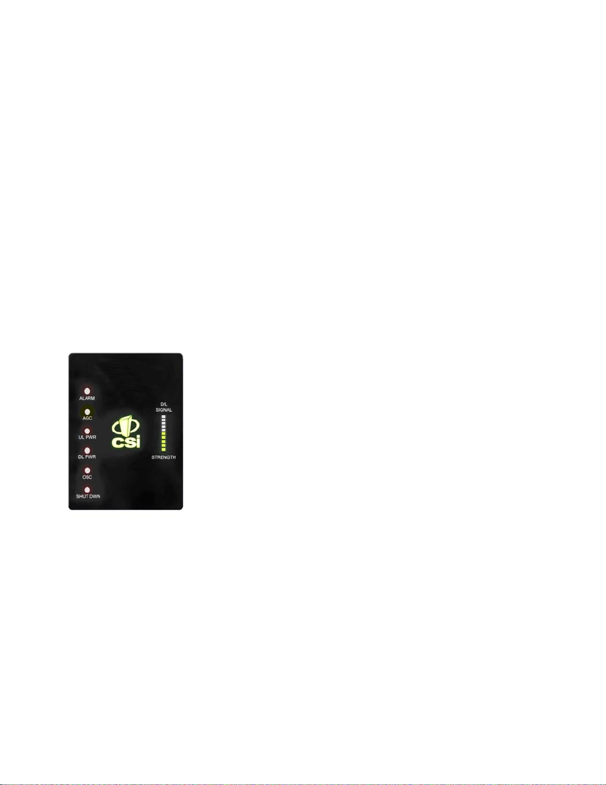
LED Indicators
Automatic safety precautions are built into the amplifier system. In the case of a catastrophic system event, a shutdown circuit is
incorporated that will disable all emissions should the uplink input or downlink input be overdriven or should an oscillation or output
overpower event occur. The amplifier will periodically attempt to recover from the detected condition automatically. Warning light
indicators are as follows:
Alarm: Indicated by a red LED. The unit has sensed an alarm condition. This LED may
light alone or in conjunction with one of the other indicator LEDs. In both cases the
cause(s) can be reviewed by going to the System Health menu.
AGC: When Illuminated, this yellow LED indicates that automatic gain control is active
UL PWR: Indicated by a red LED. Uplink power has been affected by a system event and
DL PWR: Indicated by a red LED. Downlink power has been affected by a system event
OSC: Indicated by a red LED. An oscillation event has occurred or is occurring. The
SHUT DWN: Indicated by a red LED. The RF stages of the unit are disabled due to an
the air. The problem will need to be addressed by a technician before the on
D/L SIGNAL
STRENGTH: Indicated by a green LED bargraph. This indicates the relative signal strength
and has reduced the gain of the unit in order to prevent very strong input
signals from overloading the amplifier. The amplifier will periodically evaluate
input signal and attempt to recover from this condition.
will need to be addressed by either the system software or a technician to
be reset to original system settings, using the GUI or text menu interface.
See the event log to determine the nature of the fault.
or condition, such as insufficient antenna isolation, and will need to be
addressed by either the system software or a technician to be reset to original
system settings, using the GUI or menu driven user interface. See the event log
to determine the nature of the fault.
system has been affected by the event and the problem will need to be
addressed by the system software or a technician to be reset to original ystem
settings. This is an indication of a major fault.
unresolved system event such as oscillation, effectively taking the unit off
air operation can be restarted. The repeater is not equipped with an ON/OFF
power switch. Hard power down will require that the unit be unplugged.
being received from the cell site. Note: the last bar of the bargraph will turn
red in the event of very strong adjacent channel interference.
- 7 -
Approximate Signal Strengths of Bargraph Display
The minimum measurable input level is -81 dBm at 85 dB gain, -71 dBm at 75 dB gain, -61 dBm at 65 dB gain, and -51 dBm at 55 dB
gain.
ILLUMINATED
BARS
10
9
8
7
6
5
4
3
2
1
SIGNAL AT INPUT
CONNECTOR
Adjacent Channel
Interference
-54dBm to -51dBm
-58dBm to -55dBm
-62dBm to -59dBm
-66dBm to -63dBm
-70dBm to -67dBm
-74dBm to -71dBm
-78dBm to -75dBm
-81dBm to -79dBm
< -81 dBm
0*
*Note: During Power up, the CSI-DSP85-PSS8 will require a approximately three minutes for the internal computer to boot up.
During this time the LEDs on the front panel will light and go out several times. When boot is complete and no alarm conditions exist,
none of the LED indicators will be illuminated. The CSI logo is illuminated when ever the repeater is powered. One or more bars on the
LED bargraph may also be lit, depending on the strength of the signal being received from the donor site. Signals weaker than -81dBM
will not illuminate any bars.
Do not unplug the unit while it is in the boot up process!
Local Communication Interface Ports
To allow monitoring and control, the CSI-DSP85-PSS8 is equipped with four ports that provide external communication access (1
Ethernet CAT-5, 2 DB-9 serial, and 1 USB). The Ethernet, CAT-5 port is provided as a primary communications port to the PC. One
serial interface provides communications to local PC and the second to an external modem when provided. The USB interface
provides a means to download files from a memory device and may also be used by an external modem. The DB-9 pin assignments conform to the standard Electronic Industries Association (EIA232) specification. A diagram of the pin descriptions is
provided on this page for reference.
Connecting a null modem cable to one of the COM ports and using a terminal emulation program with a PC will allow communication
to the control processor’s Text Menu Interface (TMI). See command line interface section for further detail.
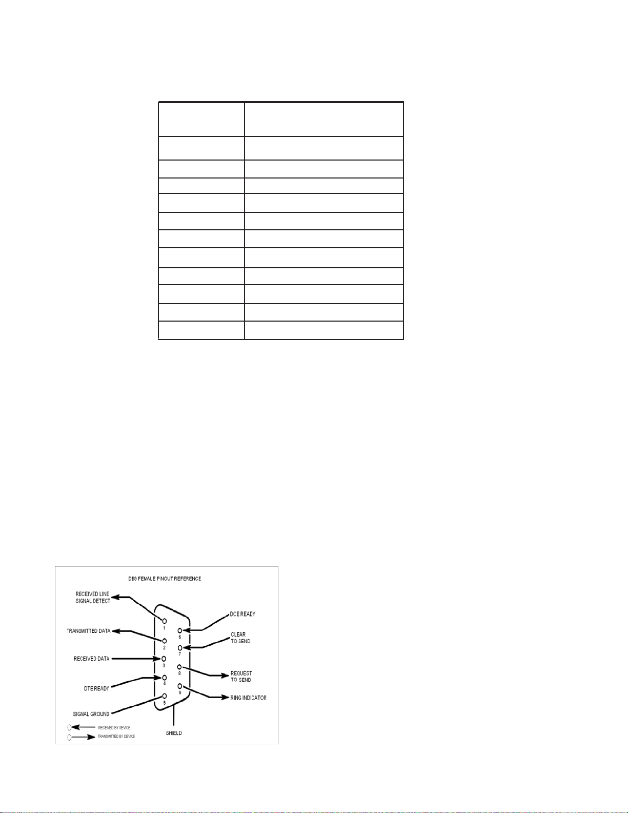
EIA232 Pin Specifications
The diagram to the left is for reference only, it’s intended to provide
a quick source for pinout information in the event it should be
necessary to adapt your serial cable because of an unusual
connector configuration. In the vast majority of cases this
information will not be needed.
USB Interface
The Universal Serial Bus (USB) interface conforms to
Intel’s Universal Host Controller Interface (UHCI) version
1.1 dated March 21, 1996. This interface will support data
transfer rates up to 12 Mbps and can be used for software updates and filter file uploads.
Ethernet
The Ethernet AUI conforms to IEEE 802.3 and is capable of
supporting 10/100 Mbps communications speeds. This port is
used to provide access to the GUI.
-8-

Monitoring & Alarms
There are no physical connections provided to specifically communicate system or alarm status. This information is embedded in the
information accessible via the communication ports described earlier.
System Set-Up Considerations
All cables should be checked for shorts and opens. Also verify that there are no cables with loose or poor connections. RF leakage
could cause oscillation to occur under some conditions.
The rooftop antenna (Donor Antenna), if directional, should be checked for proper alignment along the calculated
compass heading. Typically, the directional antenna would be aimed at the same site that your handset uses, but it may
not always be so. It is critical the installer contact the service provider for information on, and approval
of, the site he or she has selected before the system is turned on.
If cables and alignment are acceptable and a problem persists, it may be necessary to use a spectrum analyzer to
examine the signal environment in which the CSI-DSP85-PSS8 is operating. The existence of strong adjacent channel
signals within the frequency band(s) can cause the AGC to reduce the amplifier’s gain or cause alarms. In some cases
additional filtering or attenuation might be required to reject these unwanted signals. In some instances, the donor
antenna can be reoriented horizontally, to place the interference source in an antenna pattern “null”. There also may be
some cases where the interference from outside signals is so great that they cannot be filtered or otherwise reduced
or eliminated without expensive and possibly prohibitive measures. In these cases it may not be practical to use the
CSI-DSP85-PSS8 for providing coverage to these sites.
Selection of external attenuators to be used in line with the CSI-DSP85 Antenna
Port(s):
DONOR PORT (To Outside Antenna, see port configuration diagram next page.)
If a CSI-DSP85 is installed in an area with very strong desired and/or undesired signals, it is important to ensure that the overall
signal levels are optimized to be within the best operating range of the repeater. Additionally, de-sensing of a nearby base station
site must be avoided. These goals can be accomplished by properly attenuating the antenna port(s) in the path of the donor
antenna(s). In effect, one can imagine that the particular repeater deployment is electrically moved farther from the base station
using attenuators that are equivalent to increasing the path loss from the donor antenna to the base station. The following potential
outcomes result from the use of attenuators on the donor port(s) of the CSI-DSP85: Uplink output power, as reported by the CSIDSP85, is reduced by the value of the attenuation, protecting nearby base stations. Downlink signal to noise ratio is high at the point
of the attenuator, resulting in slight but negligible reduction in downlink performance. Other performance is essentially unchanged.
SERVER PORT (To Inside Antenna(s), see port configuration diagram next page.)
Server port attenuation may also be necessary, particularly where a powered DAS is present. The selection guidelines below apply
to both server and donor ports. In order to properly measure uplink signal strength, a signal generator should be used. If a signal
generator is not available, placing a test call while under the server antenna with the least path loss to the repeater should provide
reasonable data. The following potential outcomes result from the use of attenuators on the server port(s) of the CSI-DSP85:
Downlink output power, as reported by the CSI-DSP85, is reduced by the value of the attenuation. Uplink incoming power from the
DAS is reduced, along with potentially strong and/or harmful out-of-band signals (including noise) that are generated by the DAS.
- 9 -
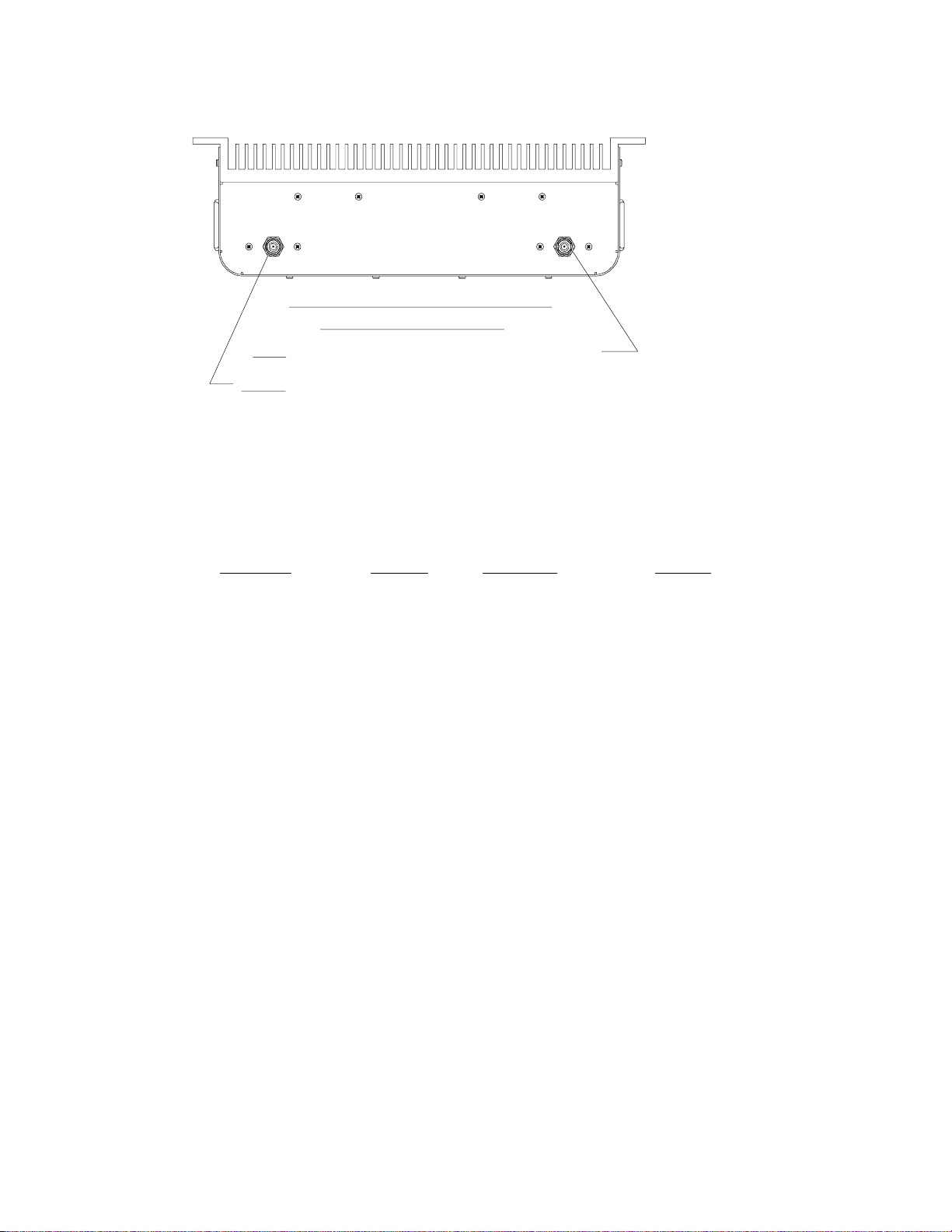
TO INSIDE ANTENNA
TO OUTSIDE ANTENNA
1:1 PORT CONFIGURATION
STANDARD MODEL
Input: One single band port, from the single band donor.
Output: One single band port to the DAS.
Attenuator Selection Guidelines:
Accurate attenuator values need to be chosen to ensure that the maximum total power (higher of Composite or In-Band Input)
applied to the donor and server port(s) does not exceed the following thresholds:
Input Signal Max Gain Input Signal Max Gain
-54 dBm 84 dB -38 dBm 68 dB
-53 dBm 83 dB -37 dBm 67 dB
-52 dBm 82 dB -36 dBm 66 dB
-51 dBm 81 dB -35 dBm 65 dB
-50 dBm 80 dB -34 dBm 64 dB
-49 dBm 79 dB -33 dBm 63 dB
-48 dBm 78 dB -32 dBm 62 dB
-47 dBm 77 dB -31 dBm 61 dB
-46 dBm 76 dB -30 dBm 60 dB
-45 dBm 75 dB -29 dBm 59 dB*
-44 dBm 74 dB -28 dBm 58 dB*
-43 dBm 73 dB -27 dBm 57 dB*
-42 dBm 72 dB -26 dBm 56 dB*
-41 dBm 71 dB -25 dBm < 55 dB*
-40 dBm 70 dB
-25 dBm is the maximum input signal level that should be applied to the repeater, even if the gain is lower than 55 dB.
Input signals exceeding these thresholds will result in composite input attenuation, called “ADC Protect” (Analog to Digital Converter
Protection). Output power is reduced whenever the above thresholds are exceeded by reducing the gain by 1dB for each 1 dB that
the threshold is exceeded. ADC Protect should not be confused with AGC (Automatic Gain Control), which reduces gain to prevent
In-Band (measured) output power from exceeding the specified maximum output level. To determine the total power applied to the
donor and server ports, please reference the “Composite Input” values as reported in the Web (“System Status”) or Menu (“Link
Status”) interfaces (depicted and explained later in this manual).
Large delta’s between in-band and composite input signals:
Care should be taken to isolate the best donor site to ensure the least possible delta between in-band and composite downlink
signals. If the (downlink) composite input exceeds the in-band input by more than 3 dB for the SMR band the maximum output power
will be reduced. Example:
Band (SMR)
In-Band Input -45 dBm
Composite Input -38 dBm
Max Gain = 68 dB
Max Output = 23 dBm
<-55 dBm 85 dB -39 dBm 69 dB
*We recommend padding this level due to potential for fluctuating signal.
- 10 -
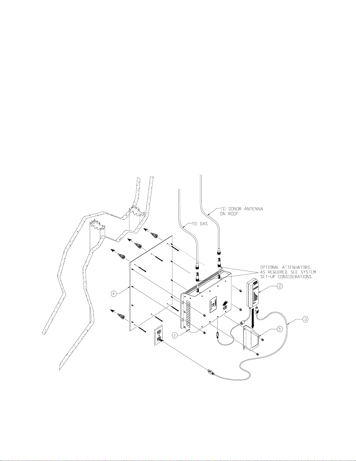
Wall Mounting the CSI-DSP85-PSS8, Digit al Repeater
The following diagram illustrates the best method for mounting the repeater to a wall in an typical installation.
Note: for optimal cooling the unit should be mounted vertically on a wall with the antenna ports up.
ITEM # QTY PART # DESCRIPTION
1 1EA CS10-410-402 DSP85-PSS8 REPEATER
2 1EA 453-1010-002 5V/24V POWER SUPPLY
3 1EA 780-0510-001 LINE CORD (AC POWER)
4 1EA 750-2171-001 MOUNTING PLATE (OPTIONAL)
5 1EA 750-2172-002 P/S MOUNTING BRACKET
- 11 -
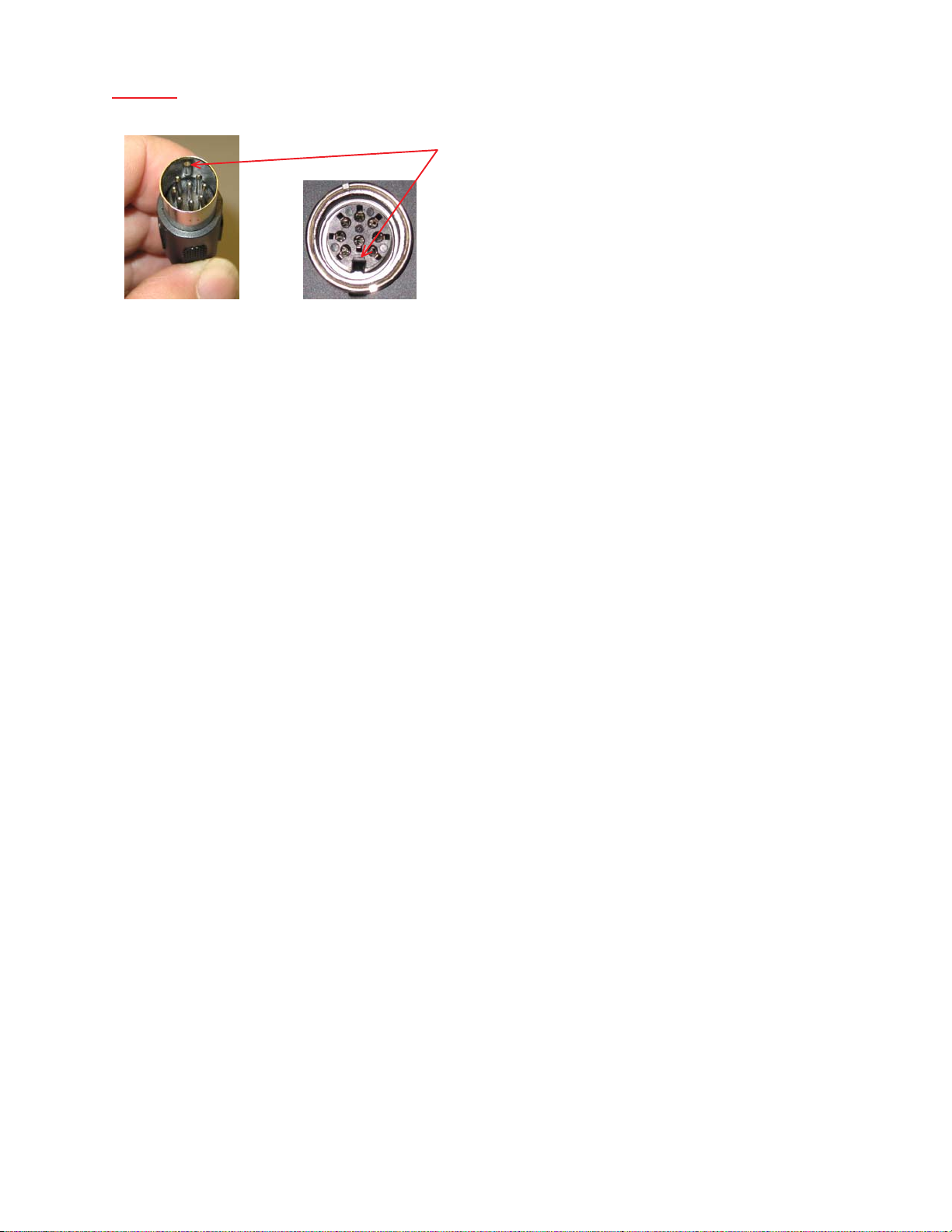
Warning: On the standard model, power supply cable connectors are keyed for proper orientation, but if forced can be
inserted incorrectly. Great care should be taken to avoid this as it may damage the connectors and/or the repeater. This does
not apply to the weather resistent model, which uses an internal power supply
Keyed for proper alignment, do not force
connector into place.
Optional Accessories
A complete line of accessories is available from Cellular Specialties, Inc. Check with your CSI distributor for any additional items
needed. Below are just a few examples suitable for most in-building needs.
•Outside Donor Antenna
Yagi - model number: CSI-AY/806-960/14
•Inside Omnidirectional Antenna
Quad-band - model number: CSI-AO/700/2.5K/3
•Directional Couplers
6dB - model number: CSI-DC6/700-2K/N
10dB - model number: CSI-DC10/700-2K/N
15dB - model number: CSI-DC15/700-2K/N
20dB - model number: CSI-DC20/700-2K/N
30dB - model number: CSI-DC30/700-2K/N
•UPS
Battery backup, 2 hr Single band
1 hour dual band - model number: CS48-985-600
Battery backup, 4 hr Single band
2 hour dual band - model number: CS48-985-601
•Power Dividers
2:1 - model number: CSI-SPD2/700-2.5K/N
3:1 - model number: CSI-SPD3/700-2.5K/N
4:1 - model number: CSI-SPD4/700-2.5K/N
•Grounding Kit - model number: CSI-GKIT
•Lightning Arrestor - model number: CSI-CAP
•Mounting Kit
19” rack or wall mountable -
model number: CSI-RWM-DSP85
Important Installation Notes
• Inadequate isolation between the outside and inside antennas may cause regenerative feedback in the system. This
feedback can cause the amplifier to emit a continuous signal at maximum amplitude and, in some cases, interfere with normal
operation of the dispatch site. Careful consideration of the layout and placement of the system is imperative.
• The installer should refer to the Safety Guidelines section on page 4 and the Important Safety Information section on page 5 for
proper antenna selection and installation. To avoid serious injury or death and damage to the repeater, do not install donor or server
antennas near overhead power lines or high power components. Allow enough distance so that if antennas should fall they will
not come in contact with those components.
••
• Close proximity to the donor or server antennas with the repeater in operation may expose the user or installer to RF fields
••
that exceed FCC limits for human exposure.
WARNING! AMPLIFIER OR HANDSET DAMAGE MAY OCCUR IF A HANDSET IS CONNECTED DIRECTL Y T O THE REPEATER OR THE
COAX THA T LEADS TO THE REPEA TER.
Circuit Operational Description
The repeater uses a single down-conversion/up-conversion scheme. There are multiple RF amplifier stages prior to each downconverting mixer. The down-converting mixers are followed by a single IF amplifier. A Digital Signal Processor block then processes
the resultant digitized IF signal that was previously generated by an Analog-to-Digital Converter. The processed (filtered) digital signal
is fed to a Digital-to-Analog converter and then up-converted to RF. A driver amplifier and a final power amplifier make up the final gain
stages before application to the diplexer. The maximum total system gain (diplexer input to diplexer output) is nominally 85 dB for either
the downlink or the uplink paths with both links having independent manual and automatic gain controls (AGC).
AGC reacts to analog power detection on both the input and output of the uplink and downlink RF chains. A control algorithm
continuously monitors these detected values and dynamically adjusts various gain stages such that the net system gain
value, entered manually, is maintained without either exceeding FCC parameters or overdriving the A/D converters.
LEDs on the front panel display provide immediate visual indications of the unit’s primary power and major or minor alarm
status. The repeater features automatic shutdown protection, as a safety measure, should excessive drive be applied to the
input or an oscillation condition occur. When in a protected mode, a control algorithm determines the appropriate method of
recovery to a normal, previously defined state, or maintains the protection until manually reset. If recovery has been established, the associated LED(s) will either be extinguished or available to be reset. The events
that trigger the error will be saved in the event log.
-12-
 Loading...