

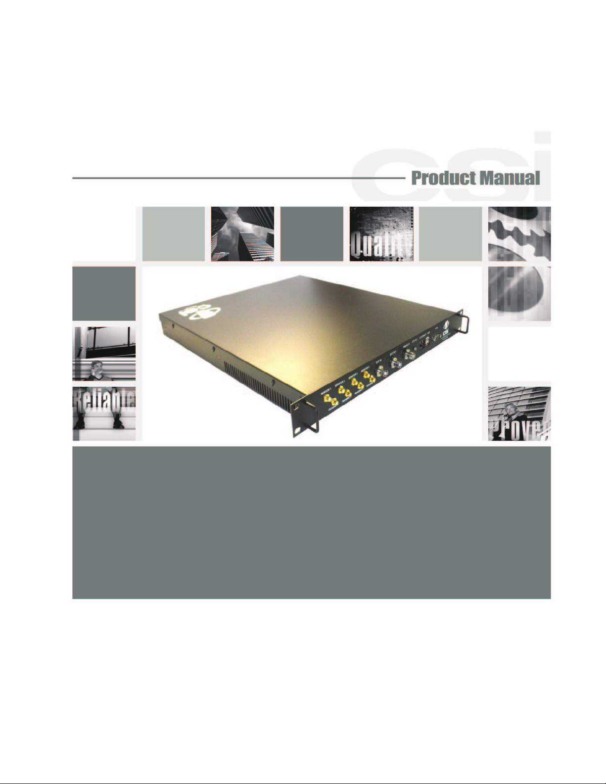
Westell CSICPBHMG C4 User Manual
CSI-CPBH-MG-C4, CSI-CPBH-MG-P4,
CSI-CPBH-MG-C2/P2, CSI-CPBH-MG-AW4,
CSI-CPBH-MG-C2/AW2, CSI-CPBH-MG-P2/AW2,
CSI-CPBH-MO-C4, CSI-CPBH-MO-P4,
CSI-CPBH-MO-C2/P2, CSI-CPBH-MO-AW4,
CSI-CPBH-MO-C2/AW2, CSI-CPBH-MO-P2/AW2,
CSI-CPBH-MX-C4, CSI-CPBH-MX-P4,
CSI-CPBH-MX-C2/P2, CSI-CPBH-MX-AW4 ,
CSI-CPBH-MX-C2/AW2, CSI-CPBH-MX-P2/AW2,

Table of Contents
Product Registration Information ........................................................................................................................ 4
Document Purpose / Intended Users ................................................................................................................. 4
Radio and Television Interference ...................................................................................................................... 4
Application .......................................................................................................................................................... 4
Safety Guidelines ............................................................................................................................................... 4
Important Safety Information .............................................................................................................................. 4
Acronyms and Defi nitions ................................................................................................................................... 5
Product Introduction ........................................................................................................................................... 5
Functional Overview ........................................................................................................................................... 6
Electrical Characteristics .................................................................................................................................... 6
Mechanical Specifi cations .................................................................................................................................. 6
AC Power Specifi cations .................................................................................................................................... 6
Environmental Requirements ............................................................................................................................. 6
Mechanical Drawing ......................................................................................................................................... 7
System Set-Up Considerations .......................................................................................................................... 7
Mounting the Co-Pilot Beacon ............................................................................................................................ 7
Typical Co-Pilot/BTS Interconnection with Internal CDMA Timing (MO Series) ................................................. 8
Typical Co-Pilot/Repeater Interconnection with Internal GPS Timing (MG Series) ............................................ 9
Typical Co-Pilot/Repeater Interconnection with External TM-4 (MX Series) .................................................... 10
Optional Accessories .........................................................................................................................................11
Important Installation Notes ...............................................................................................................................11
Powering Up the Unit.........................................................................................................................................11
Local Communication Interface Ports................................................................................................................11
Web based GUI Session .................................................................................................................................. 12
Element Management System ......................................................................................................................... 13
System Info Tab ................................................................................................................................................ 13
System Status and Confi guration Tab .............................................................................................................. 14
Administration Tasks Panel .............................................................................................................................. 15
Supplemental Confi guration Tab ...................................................................................................................... 16
SNMP Confi guration Tab .................................................................................................................................. 16
Alarms Tab ........................................................................................................................................................ 17
Setup Element Confi guration Tab ..................................................................................................................... 17
Special Icons .................................................................................................................................................... 18
Install Software Icon ......................................................................................................................................... 18
Copy Logs Icon................................................................................................................................................. 18
Reboot Icon ...................................................................................................................................................... 18
Collapse/Expand Icon....................................................................................................................................... 19
Alarm Status Icon ............................................................................................................................................. 19
Administration Tasks Collapse/Expand Icon .................................................................................................... 20
Elements Collapse/Expand Icon...................................................................................................................... 21
EIA232 Pin Specifi cations ................................................................................................................................ 22
USB Interface ................................................................................................................................................... 22
Ethernet ............................................................................................................................................................ 22
Monitoring & Alarms ......................................................................................................................................... 22
Text Menu Interface .......................................................................................................................................... 23
Local Access..................................................................................................................................................... 23
User Interface ................................................................................................................................................... 25
Login ................................................................................................................................................................. 25
Main Menu ........................................................................................................................................................ 25
Telnet Session (Remote Access) ...................................................................................................................... 26
Set Parameters Menu....................................................................................................................................... 26
Co-Pilot Beacon Confi guration ......................................................................................................................... 30
Transmitter Confi guration ................................................................................................................................. 30

System Confi guration ....................................................................................................................................... 31
Networking Confi guration ................................................................................................................................. 32
System Commands .......................................................................................................................................... 33
Key Features .................................................................................................................................................... 34
Multiple Beacon Confi guration.......................................................................................................................... 34
Detected RF Power Shutdown ......................................................................................................................... 34
Timing Reference Source ................................................................................................................................. 34
Control Parameter Details ................................................................................................................................ 34
Master Shutdown.............................................................................................................................................. 34
Timing Reference Selection ............................................................................................................................. 34
Channel Frequency Numbers........................................................................................................................... 35
Signal Transmit Enables ................................................................................................................................... 35
PN Offset .......................................................................................................................................................... 36
Tau (Delay Correction)...................................................................................................................................... 36
Co-pilot beacon Per Channel Transmit Power ................................................................................................. 36
Composite Transmit Power .............................................................................................................................. 36
Manual Shutdown ............................................................................................................................................ 36
Auto Shutdown Enable ..................................................................................................................................... 36
Auto Shutdown Threshold ................................................................................................................................ 36
Detected Power ................................................................................................................................................ 36
Additional Tips .................................................................................................................................................. 37
One Year Limited Warranty .............................................................................................................................. 39
Industry Certifi cations/Registration Numbers .................................................................................................. 39
Index ................................................................................................................................................................. 40

Product Registration Information
The serial number may be found on the label on the bottom panel near the power
connectors. Note this number below. Retain this manual, along with proof of purchase, to serve as a permanent record of your purchase.
MODEL NUMBER SERIAL NUMBER PURCHASE DATE
POINT OF SALE COMPANY
DISCLAIMER: All information and statements contained herein are accurate to the best of the knowledge of Cellular Specialties, Inc. (CSI), but Cellular Specialties makes
no warranty with respect thereto, including without limitation any results that may be obtained from the products described herein or the infringement by such products of
any proprietary rights of any persons. Use or application of such information or statements is at the users sole risk, without any liability on the part of Cellular Specialties,
Inc. Nothing herein shall be construed as licence or recommendation for use, which infringes upon any proprietary rights of any person. Product material and specifi cations
are subject to change without notice. Cellular Specialties’ standard terms of sale and the specifi c terms of any particular sale apply.
Document Purpose / Intended Users
The purpose of this document is to provide a step-by-step procedure to help the experienced technician/engineer install and commission
an in-building wireless enhancement pilot beacon system. Following the procedures outlined will minimize risks associated with modifying
a live system and prevent service interruptions. This document assumes the technician/engineer understands the basic principles and
functionality involved with the system. It is geared to the practical concerns of the installer.
Radio and Television Interference
NOTE: This equipment has been tested and found to comply with the limits for a Class A digital device, pursuant to Part 15 of the FCC
rules. These limits are designed to provide reasonable protection against harmful interference when the equipment is operated in a
commercial environment. This equipment generates, uses and can radiate radio frequency energy and, if not installed and used in
accordance with the instruction manual, may cause harmful interference to radio communications. Operation of this equipment in a residential area is likely to cause harmful interference in which case the user will be required to correct the interference at his own expense.
Changes and Modifi cations not expressly approved by Cellular Specialties, Inc. can void your authority to operate this equipment under
Federal Communications Commission’s rules.
Industry Canada Notice for 850 and 1900MHz Band Models
This device complies with Industry Canada licence-exempt RSS standard(s). Operation is subject to the following two conditions: (1) this
device may not cause interference, and (2) this device must accept any interference, including interference that may cause undesired
operation of the device.
Avis de conformité des modèles 850 et 1900 MHz à la réglementation d’Industrie
Canada
Cet appareil est conforme aux normes CNR d’Industrie Canada applicables aux appareils radio exempts de licence. Son exploitation est
soumise aux deux conditions suivantes: (1) cet appareil ne doit pas causer d’interférence radioélectrique, et (2) cet appareil doit accepter
toute interférence radioélectrique, incluant les interférences susceptibles d’affecter son fonctionnement de façon indésirable.
Safety Guidelines
The general safety information in this guideline applies to both operating and service personnel. Specifi c warnings and cautions will be
found in other parts of this manual where they apply, but may not appear in this summary. Failure to comply with these precautions or
specifi c warnings elsewhere in the manual violates safety standards of design, manufacture, and intended use of equipment. Cellular
Specialties, Inc. assumes no liability for the customer’s failure to comply with these requirements:
Grounding
This pilot beacon system is designed to operate from 100-240 VAC and should always
be operated with the ground wire properly connected. Do not remove or otherwise alter the
grounding lug on the power cord.
Explosive Atmospheres
To avoid explosion or fi re, do not operate this product in the presence of fl ammable
gases or fumes.
Lightning Danger
Do not install or make adjustments to this unit during an electrical storm. Use of a suitable lightning arrester, such as CSI’s model
number CSI-CAP, is very strongly recommended.
No User Serviceable Parts Inside
HAZARDOUS VOLTAGES ARE PRESENT WHEN THE COVER IS REMOVED. Opening the chassis will void your warranty. If you
suspect a malfunction with this product, call your dealer or the Cellular Specialties Support Line at: (603) 626-6677, Toll Free (USA)
1-877-844-4274.
Important Safety Information
Antennas used for the purpose of radiating signals indoors are limited to a maximum gain of 3 dBi. Each antenna must be positioned to
observe minimum separation requirements from all users and bystanders. The following guidelines should be used when considering
separation distances.
INDOOR antennas must be placed such that, under normal conditions, personnel cannot come within 20 cm (~8.0 in.) from any inside
antenna. Adhering to this minimum separation will ensure that the employee or bystander cannot exceed RF exposures beyond the maximum permissible limit as defi ned by section 1.1310 i.e. limits for General Population/Uncontrolled Exposure.
-4-

Acronyms and Defi nitions
3GPP2 The standards body comprised of representatives of interested companies that is responsible for the development
AGC Automatic Gain Control
CDMA Code Division (or, Domain) Multiple Access: The general term for the technology used in the CDMA2000 system as
Chip A single element, a ‘1’ or a ‘0’, of the PN Sequence in a CDMA system. The chip rate for the CDMA2000 system is
CSI Cellular Specialties Incorporated
DAS Distributed Antenna System
ERP Effective Radiated Power
EST Even Second Tick: In the CDMA2000 cellular system all time values are referenced to the start of the even seconds
FCC Federal Communications Commission
FPGA Field Programmable Gate Array
GPS Global Positioning System
IF Intermediate Frequency
LED Light Emitting Diode
NEMA National Electrical Manufacturers Association
PA Power Amplifi er
PN Pseudo random Number: A number chosen by some algorithm that approximates a random process. Can be short
PN Number In the CDMA2000 system only a subset of the possible PN Offsets are used for base station identifi cation. Each of
PN Offset In the CDMA2000 System each base station is identifi ed by the offset in time from the EST at which the start of the
PN Sequence A sequence of pseudo random numbers. In the CDMA2000 system several such sequences are used. The one
PPS Pulse per Second: Refers the pulse repetition rate of the timing signal used as a time reference.
RF Radio Frequency
SBC Single Board Computer
Tau Timing Offset or Delay Adjustment: In the CDMA2000 system the timing of the downlink signal is required to be
USB Universal Serial Bus
and maintenance of the operational standards for the CDMA2000 system. Http://www.3gpp2.org
well as others. Also a shorthand reference to the CDMA2000 system and its derivatives such as 1xEV-DO
1.2288 Mchips/second.
of time as indicated by GPS.
for “PN Sequence”, “PN Number”, or “PN Offset” when discussing the CDMA2000 system.
these allowed offsets is given a unique number from 0 to 511.
Pilot PN Sequence occurs. The offset is specifi ed in terms of number of chips.
relevant to ICEBreaker is the Pilot, or Short, sequence which is a 215 element long sequence of ones and zeros.
aligned with the EST as it is transmitted from the antenna. Tau allows the timing of the internal PN Sequence to
be adjusted to compensate for the delays of the base station hardware such that the timing will be correct at the
antenna
Product Introduction
The pilot beacon generator facilitates E911 and other location based services (LBS) for in building and/or DAS based installations of
CDMA2000/1xEV-DO cellular networks. In these situations the normal methods based for location determination, direct reception of
GPS by the mobile station or triangulation using the signals from multiple base stations, do not work. Signals from the GPS system are
suffi ciently weak that even if the mobile station’s GPS receiver might ultimately be able to lock on to the satellites, the acquisition time will
be too long. And since indoor service is typically provided either by a single strong local cell or by using a repeater, there aren’t multiple
signals on which to triangulate while DAS based deployments result in too many signals with indeterminate timing. By placing a pilot
signal at a known PN offset the LBS algorithm can quickly and reliably be made aware that it is within a specifi c building or other location
where normal location determining solutions are ineffective. This information can be used to aid the GPS receiver in acquiring signals if
present or be used as a position report directly until more accurate information becomes available.
they are
-5-

Functional Overview
Number of Bands per Beacon
CDMA Band Class
Max # Simultaneous Channels/Beacon
Number of Unique PN Offsets/Beacon
Composite TX Power
Spurious Emissions Limits
Carrier Frequency Accuracy
Pilot Timing Jitter
Rho > 0.98
Tau Adjustment Range
Tau Adjustment Resolution 20 nsec (one 40th of a CDMA chip)
Parameter Specifi cation Notes
Pilot Beacon Size
Height 1.73 in.
Electrical Characteristics
Characteristic
Mechanical Specifi cations
Performance Limit
0 (Cell), 1 (PCS) and 15 (AWS)
8 (Cell) 11 (PCS and AWS)
< -45 dBc Δf .75 to 1.98 MHZ
< -60 dBc Δf 1.98 to 4.0 MHZ
< -65 dBc Δf 4.0 to 16 MHZ
< -75 dBc Δf > 16 MHZ
20 Hz (.2 ppm) Cell Band
40 Hz (.2 ppm) PCS Band
45 Hz (.2 ppm) AWS Band
< 10 nsec rms, <50 nsec peak
- 166.7 to + 166.7 µsec (+/- 25.6 CDMA chips)
1
1
+20 dBm
When locked to GPS
Width 19.00 in.
Depth 18.02 in.
Weight 8.4lbs / 3.8kg
Thermal Management Fan Cooled
Surface Coating Powder Coat
Color Satin Black
AC Power Specifi cations
Parameter Specifi cation Notes
AC Voltage 100 - 240 VAC External Power Supply
AC Current 1.7 Amps @ 120 VAC
0.9 Amps @ 230 VAC
AC Power Frequency 47 - 63 Hz
Heat Output 500 BTU/Hr
Environmental Requirements
Parameter Specifi cation Notes
Temperature Range -30° to +48°C
(-22° to +118°F)
Relative Humidity 5% to 95% Non-condensing
-6-
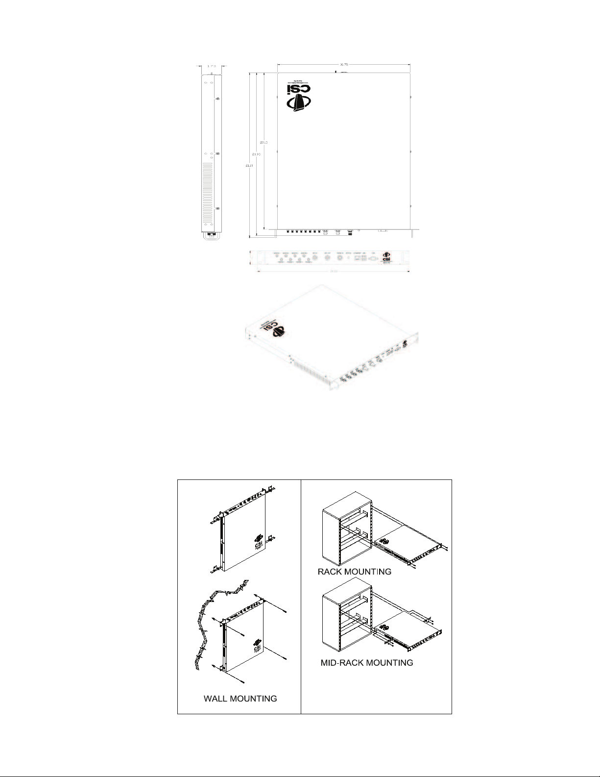
Mechanical Drawing
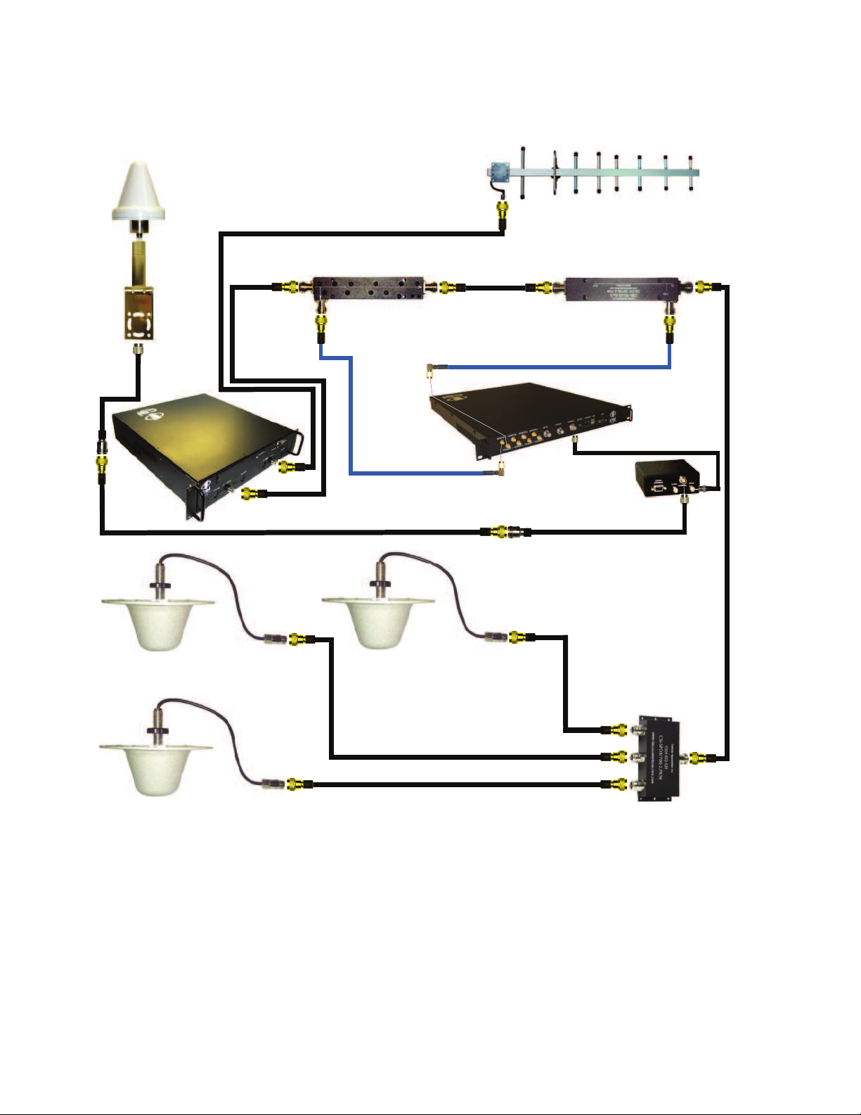
System Set-Up Considerations
All cables should be checked for shorts and opens. Also verify that there are no cables with loose or poor connections. It is critical that
the installer contact the service provider before the system is turned on.
Mounting the Co-Pilot Beacon
The following diagram illustrates the best method for mounting the pilot beacon to a wall in an typical installation.
-7-
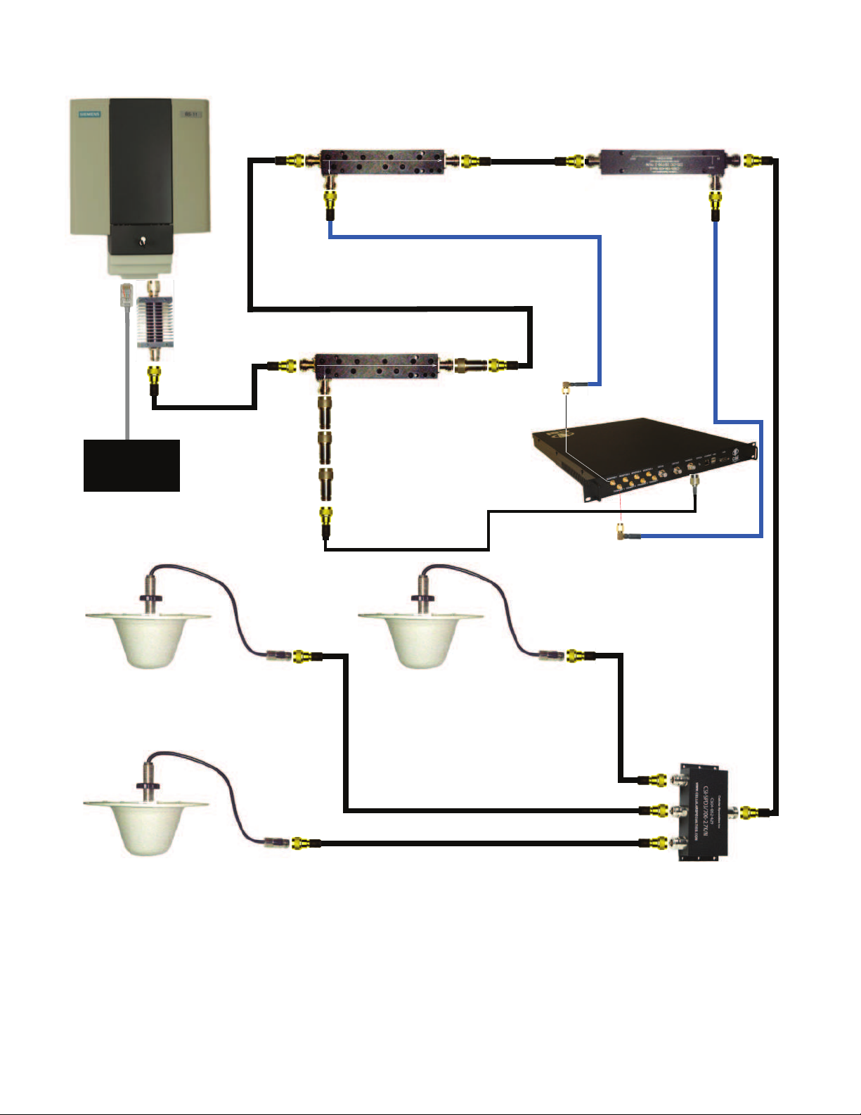
+9.6dBm
+9.0dBm
-10.4dBm
Directional Coupler 2 (-20dB)
+8.9
dBm
+8.3dBm
-15.1dBm
Directional Coupler 3 (-20dB)
+20.0dBm
BTS
Co-Pilot Beacon (MO Series)
Equipped with Praecis II CDMA
Timing Module
-10.5dBm
+20.0dBm
-0.1dBm
-15.2dBm
-50.2dBm
DAS
RF
Jumper
NM-NM
RF Jumper
NM-NM
IN
OUT
-20dB
RF Jumper
NM-SMAM
RF
Jumper
NM-SMAM
-15.8dBm
-15.9dBm
IN
OUT
-20dB
See note 4
Network
IN
OUT
-30dB
Directional Coupler 1 (-30dB)
RF Jumper
NM-NM
+19.9dBm
20dB Fixed
Attenuator
RF Jumper
NM-TNCM
-10.1dBm
-60.1dBm
+9.7dBm
-16.0dBm
+19.9dBm
-68.5dBm
-16.2dBm
-138.5dBm
-138.6dBm
20dB Fixed
Attenuator
See note 6
Notes:
1. It is recommended that all unused ports be terminated at 50 ohms. When properly terminated, the possibility of false shutdown is minimized because high reflections at open
ports are eliminated.
2. The values shown in this drawing are only an example. Power levels encountered at each installation may require different coupling, pads, and threshold values.
3. This example assumes a BTS with power at the output set to 40dBm, co-pilot beacon output set at 20dBm.
4. Threshold Power Level in this example is set to -20dBm (Approximately 10dB below the power level at the monitor input.)
5. DAS Power Detection and Shutdown functionality:
- If RF Detector measures Input power lower than the Threshold Power Level set by
the user, then the Co-Pilot Beacon’s RF power output will be shut down.
- An alarm occurs. (Delay approximately one second on-off and one second off-on.
6. Co-pilot beacon signal reflecting back to the input of the CDMA timing source must never be allowed to exceed -124dBm.
-60.2dBm
10dB Fixed
Attenuator
10dB Fixed
Attenuator
20dB
Fixed
Attenuator
Typical Co-Pilot/BTS Interconnection with Internal CDMA Timing (MO Series)
-8-
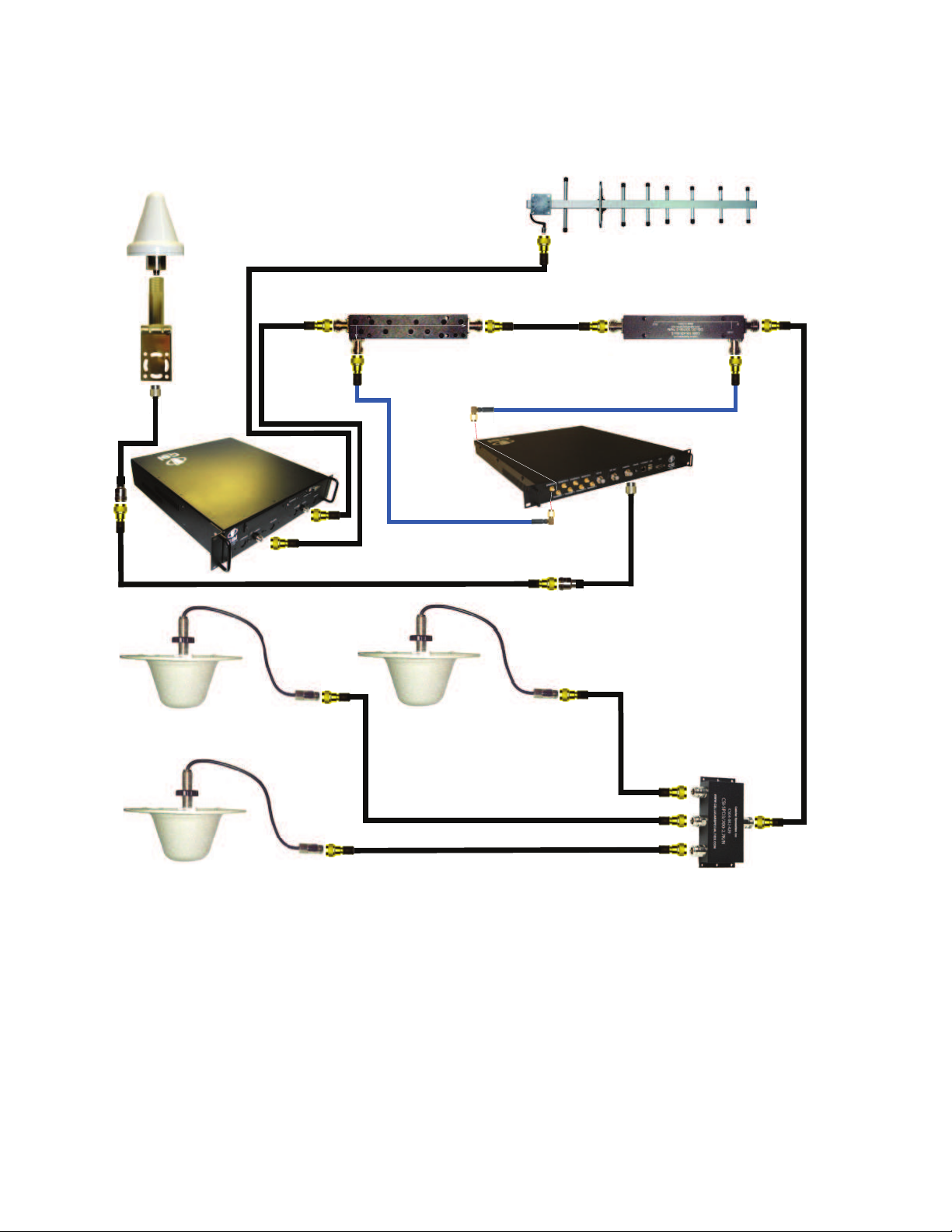
Typical Co-Pilot/Repeater Interconnection with Internal GPS Timing (MG Series)
9.9dBm
+9.3dBm
-10.1dBm
Directional Coupler 1
+9.2dBm
+8.6dBm
-15.1dBm
Directional Coupler 2
+10.0dBm
Donor
-75.0dBm
-10.2dBm
-0.1dBm
-15.2dBm
-50.2dBm
DAS
IN
OUT
-20dB
+19.9dBm
-15.8dBm
-15.9dBm
IN
OUT
-20dB
See note 4
GPS Antenna
Antenna
Bracket
RF
Jumper
NF-TNCM
RF Jumper
NM-SMAM
RF Jumper
NM-SMAM
+20.0dBm
RF Jumper
NF-TNCM
RF
Jumper
NM-NM
RF
Jumper
NM-NM
Co-Pilot Beacon (MG Series)
Equipped with Trimble Embedded
GPS Timing Receiver
Notes:
1. It is recommended that all unused ports be terminated at 50 ohms. When properly terminated, the possibility of false shutdown is minimized because
high reflections at open ports are eliminated.
2. The values shown in this drawing are only an example. Power levels encountered at each installation may require different coupling, pads, and threshold
values.
3. This example assumes -75dBm input at the repeater, repeater gain set to 85dB, co-pilot beacon output set at 20dBm and use of 20dB directional
couplers with 20dB coupling, and assumed 15dB worst case directivity.
4. Threshold Power Level in this example is set to -20dBm (Approximately 10dB below the power level at the monitor input.)
5. DAS Power Detection and Shutdown functionality:
- If RF Detector measures Input power lower than the Threshold Power Level set by the user, then the Co-Pilot Beacon’s
RF power output will be shut down.
- An alarm occurs. (Delay approximately one second on-off and one second off-on.
Repeater
-9-
+9.9dBm
+9.3dBm
-10.1dBm
Directional Coupler 1
+
9.2dBm
+8.6dBm
-15.1dBm
Directional Coupler 2
+10.0dBm
Donor
-75.0dBm
-10.2dBm
-0.1dBm
-15.2dBm
-50.2dBm
DAS
IN
OUT
-20dB
+19.9dBm
-15.8dBm
-15.9dBm
IN
OUT
-20dB
See note 4
GPS Antenna
Antenna
Bracket
RF
Jumper
NF-TNCM
RF Jumper
NM-SMAM
RF Jumper
NM-SMAM
+20.0dBm
RF Jumper
NF-TNCM
RF Jumper
NM-NM
RF
Jumper
NM-NM
Co-Pilot Beacon (MX Series)
Notes:
1. It is recommended that all unused ports be terminated at 50 ohms. When properly terminated, the possibility of false shutdown is minimized because high
reflections at open ports are eliminated.
2. The values shown in this drawing are only an example. Power levels encountered at each installation may require different coupling, pads, and threshold values.
3. This example assumes -75dBm input at the repeater, repeater gain set to 85dB, co-pilot beacon output set at 20dBm and use of 20dB directional couplers with
20dB coupling, and assumed 15dB worst case directivity.
4. Threshold Power Level in this example is set to -20dBm (Approximately 10dB below the power level at the monitor input.)
5. DAS Power Detection and Shutdown functionality:
- If RF Detector measures Input power lower than the Threshold Power Level set by
the user, then the Co-Pilot Beacon’s RF power output will be shut down.
- An alarm occurs. (Delay approximately one second on-off and one second off-on.
Repeater
RF Jumper
BNCM-TNCM
TM-4
Typical Co-Pilot/Repeater Interconnection with External TM-4 (MX Series)
-10-
Warning: Power supply cable connector is keyed for proper orientation and is designed to lock into place.
Keyed for proper
alignment, do not
force connector
into place.
Optional Accessories
A complete line of accessories is available from Cellular Specialties, Inc. Check with your CSI distributor for any additional items needed.
Below are just a few examples suitable for most in-building needs.
• Inside Omnidirectional Antenna
Quad-band - model number: CSI-AO/700/2.7K/3
• Directional Couplers
6dB - model number: CSI-DC6/700-2.7K/N
10dB - model number: CSI-DC10/700-2.7K/N
15dB - model number: CSI-DC15/700-2.7K/N
20dB - model number: CSI-DC20/700-2.7K/N
30dB - model number: CSI-DC30/700-2.7K/N
Battery backup, 4 hr Single band
2 hour dual band - model number: CS48-985-601
• Power Dividers
2:1 - model number: CSI-SPD2/700-2.7K/N
3:1 - model number: CSI-SPD3/700-2.7K/N
4:1 - model number: CSI-SPD4/700-2.7K/N
• Grounding Kit - model number: CSI-GKIT
• Lightning Arrestor - model number: CSI-CAP
Important Installation Notes
• The installer should refer to the Safety Guidelines section and the Important Safety Information section for proper antenna selection and
installation. To avoid serious injury or death and damage to the pilot beacon, do not install server antennas near overhead power lines or
high power components. Allow enough distance so that if antennas should fall they will not come in contact with those components.
• Close proximity to the server antennas with the pilot beacon in operation may expose the user or installer to RF fi elds that exceed FCC
limits for human exposure.
WARNING! PILOT BEACON AND/OR HANDSET DAMAGE MAY OCCUR IF A HANDSET IS CONNECTED DIRECTLY TO THE
PILOT BEACON OR THE COAX THAT LEADS TO THE PILOT BEACON.
Powering Up the Unit
During Power up, the pilot beacon will require approximately three minutes for the internal computer to boot up. During this time the LED
on the front panel may light and go out several times. When boot is complete and no alarm conditions exist, the LED indicators will be
illuminated green.
Do not unplug the unit while it is in the boot up process!
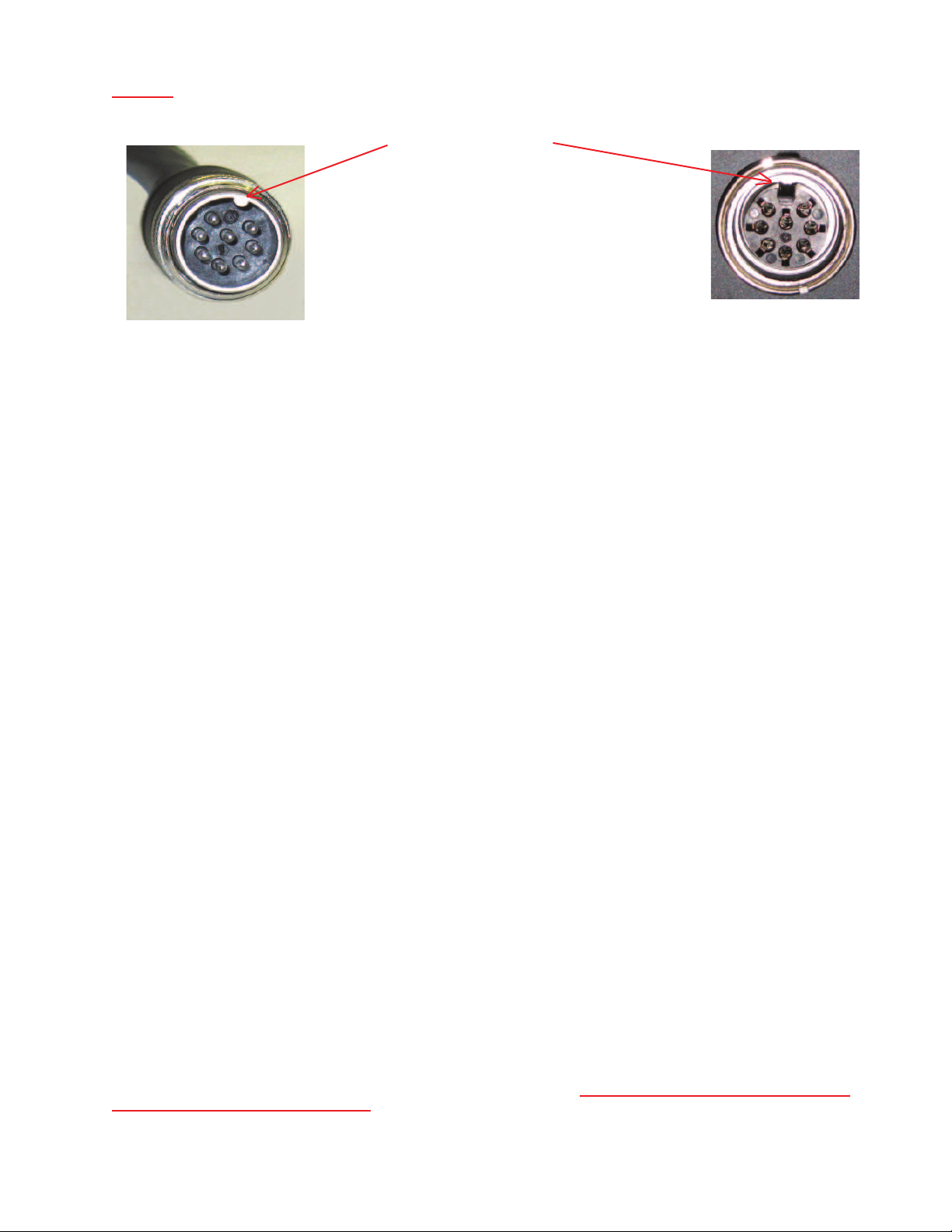
Local Communication Interface Ports
To allow monitoring and control, the pilot beacon is equipped with four ports that provide external communication access (1 Ethernet
CAT-5, 1 DB-9 serial, and 2 USB). The Ethernet, CAT-5 port is provided as a primary communications port to the PC. One serial interface, COM 1, can provide communications to local PC. The USB interface provides a means to download fi les from a memory device.
The DB-9 pin assignments of COM 1 conform to the standard Electronic Industries Association (EIA232) specifi cation. A diagram of the
pin descriptions is provided on the next page for reference.
Connecting a null modem cable to the COM 1 port and using a terminal emulation program with a PC will allow communication to the
control processor’s Text Menu Interface (TMI) for trouble shooting and advanced diagnostics. Call CSI technical support for assistance if
you need to access these advanced features or for further information.
The proprietary external GPS receiver connection is made at the port labeled “GPS”.
through serial extension cables to this port. Place the GPS receiver in a location with the best view of the unobstructed sky that is
possible, although a 100% open view of the sky is not necessary to achieve a stable time lock.
-11-
Do not connect other devices or non-straight-
Web based GUI Session
Primary access to the unit is gained using a LAN connection and a web browser program such as Firefox by Mozilla, or Internet Explorer
from Microsoft. The beacon ships with the default IP address of 192.168.1.100, but it can be changed later if required.
Connecting directly to the unit from a laptop or PC with a crossed CAT-5E cable or over a LAN the user types the IP address of the unit
into the browser address line to connect. Most users will need to update the TCP/IP settings on their computer to enable connection to a
host that has a static IP. Select “Use the following IP Address” and enter the IP Address as follows: 192.168.1.x, where “x” = any number
from 2 to 254 inclusive other than 100. The subnet mask is 255.255.255.0. Questions pertaining to these settings should be referred to
the user’s IT department or you may refer to the Additional Tips section at the end of this manual. When connection is made the user will
be prompted for a user name and password. For the purpose of the GUI session, the default user name is webuser and the password
is csi1234. This can also be changed as required. Internet access is not required to use the GUI.
verify that your Ethernet port is powered. Some laptops will not allow Ethernet connection when on battery power. If this is the case with
the laptop you are using you will need to plug it in or update the power settings. °See below for detail with regard to cables and connect-
ing to your PC.
The diagram below shows the normal use of Crossed and Straight cables.
Hub or
Co-Pilot
Beacon
Switch
If you are connecting using a laptop,
Straight Cable
Straight Cable
Co-Pilot
Beacon
Crossed Cable
Pin # Signal AT&T 258A
1 Transmit+ White/Orange
2 Transmit- Orange/White
or Orange
3 Receive+ White/Green
4 N/A Blue/White
or Blue
5 N/A White/Blue
6 Receive- Green/White
or Green
7 N/A White/Brown
8 N/A Brown/White
or Brown
Pin # Signal AT&T 258A
1 Receive+ White/Orange
2 Receive- Orange/White
or Orange
3 Transmit+ White/Green
4 N/A Blue/White
or Blue
5 N/A White/Blue
6 Transmit- Green/White
or Green
7 N/A White/Brown
8 N/A Brown/White
or Brown
8
7
6
5
4
3
2
1
8
7
6
5
4
3
2
1
PC
PC
Straight Cable
1
2
3
4
5
6
7
8
Crossed Cable
A B
1
2
3
4
5
6
7
8
-12-
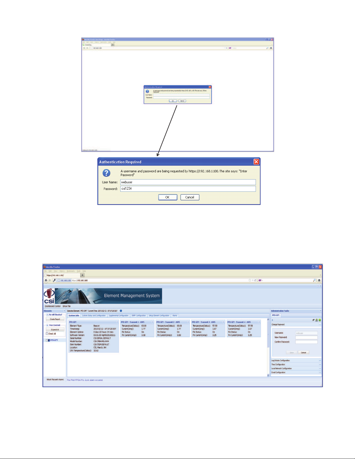
Element Management System
System Info Tab
After a successful login the Element Management System (EMS) is displayed with the System Info tab shown. This tab contains status
information about the element that is selected in the element tree.
-13-
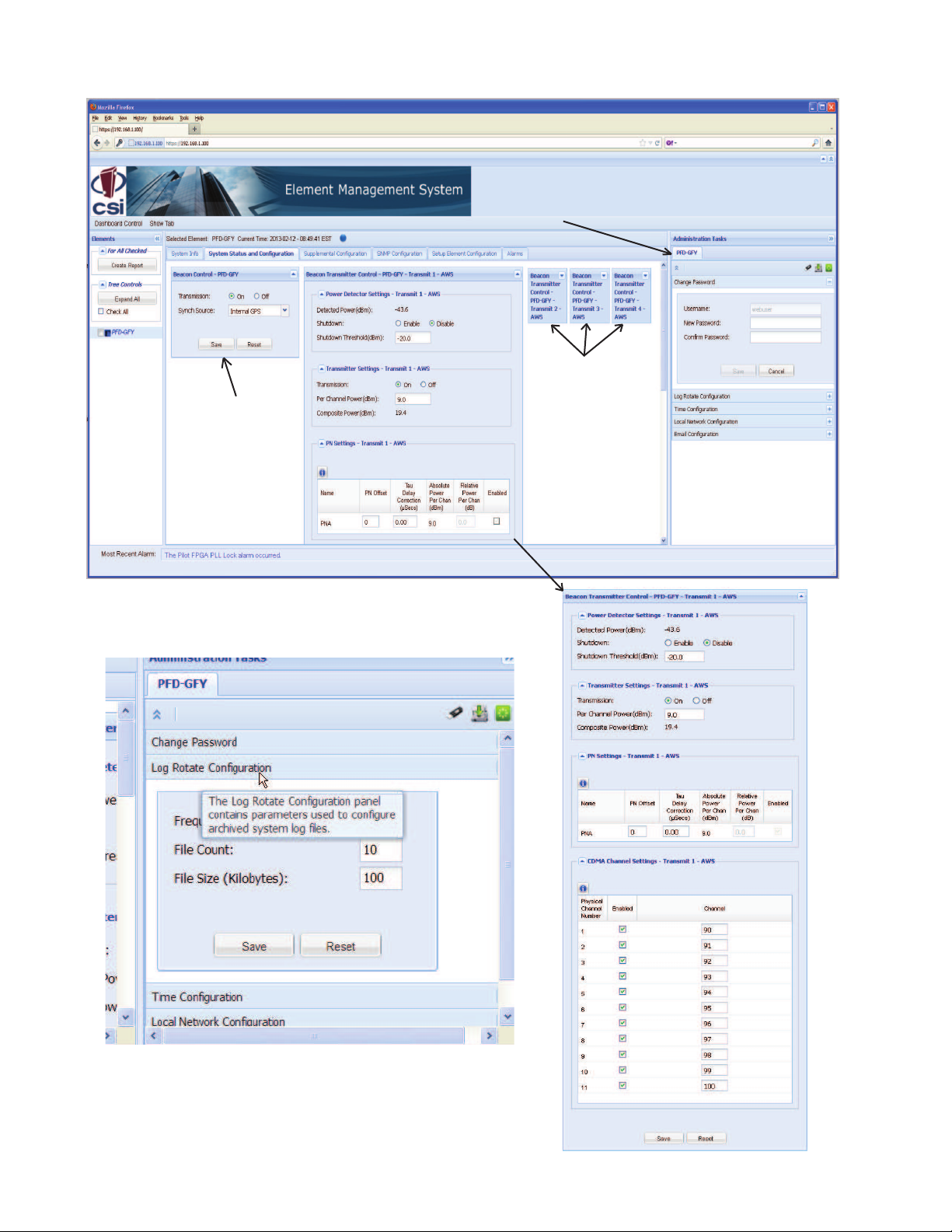
System Status and Confi guration Tab
The Beacon Control is
used to set values that
are common to all of the
Beacon Transmitters in
this element. Note - the
timing synch source
must be selected in
order to activate the
transmitters.
This tab contains various
panels that provide the ability
to change data that is related
to system administration of
the element.
Beacon Transmitter
Control panels shown
collapsed here but
can be expanded or
moved as desired by
the user.
The System Status and Confi guration tab provides the ability to change various
element specifi c parameters. The confi guration panel, expanded and displayed
here, is specifi c to the type of the element that is selected in the element tree. The
Beacon Control panel as shown here allows the user to change beacon specifi c
data such as CDMA channels
Above is illustrated the expanded Log Rotate Confi guration panel, found the
Administration Tasks section, and an important, very useful feature of the EMS, the
Tool Tips. When the user hovers his curser over any tab or icon a tool tip appears
to explain the function or feature. Because of the tool tips not all tabs, panels and
features will be shown in full detail in this manual.
-14-
 Loading...