

Westell CSI610 AP, CSI510 AP Users Manual
CSI Bi-Directional Amplifier

Table Of Contents
Product Registration/Certification Information ................ 1
Safety Guidelines .......................................................... 1
Product Information ....................................................... 2
Pin-Out Chart ................................................... 2
LED Indicators.................................................. 2
Mechanical Outline Drawing ............................. 3
Installation..................................................................... 4
Important Safety Information .......................................... 5
Performance Adjustment ............................................... 6-17
View Menu Series ............................................ 7-11
View Menu Flow Diagram ................................. 7
Edit Menu Series ............................................. 12-17
Edit Menu Flow Diagram .................................. 12
Troubleshooting ............................................................. 18
Product Warranty .......................................................... 19
Product Certification/Registration Information
The serial number may be found on the label on the rear panel of the unit. For
your convenience, note this number below. Retain this manual, along with
proof of purchase, to serve as a permanent record of your purchase for future
reference or in the event of theft.
MODEL NUMBER SERIAL NUMBER DATE OF PURCHASE
POINT OF SALE COMPANY
Safety Guidelines
The general safety information in this guideline applies to both operating and service personnel. Specific warnings and cautions will be found
in other parts of this manual where they apply, but may not appear in
this summary. Failure to comply with these precautions or specific
warnings elsewhere in the manual violates safety standards of design,
manufacture, and intended use of equipment. Cellular Specialties, Inc. assumes no
liability for the customer’s failure to comply with these requirements.
Grounding
This amplifier system is designed to operate from 120 Vac @ 1.3A maxpower
and should always be operated with the ground wire properly connected. Do
not remove or otherwise alter the grounding lug on the power cord.
Explosive Atmospheres
This product has an integral circuit breaker, which may cause an electrical flash
if the breaker should reset. To avoid explosion or fire, do not operate this product
in the presence of flammable gases or fumes.
Lightning Danger
Do not install or make adjustments to this unit during an electrical storm.
No User Serviceable Parts Inside
HAZARDOUS VOLTAGES ARE PRESENT WHEN THE COVER IS REMOVED.
Opening the chassis will void your warranty. If you suspect a malfunction with
this product, call your dealer or the Cellular Specialties Support Line at
(603) 626-6677.
DISCLAIMER: All information and statements contained herein are accurate to the best of the knowledge of
Cellular Specialties, Inc. (CSI), but Cellular Specialties makes no warranty with respect there to, including without
limitation any results which may be obtained from the products described herein or the infringement by such
products of any proprietary rights of any persons. Use or application of such information or statements is at the
users sole risk, without any liability on the part of Cellular Specialties, Inc. Nothing herein shall be construed as
license or of recommendation for use, which infringes upon any proprietary rights of any person. Product
material and specifications are subject to change without notice. Specialties’ standard terms of sale and the
specific terms of any particular sale.
- 1 -

Product Description
Cellular Specialties, Inc. (CSI) developed the LCD Model Bi-Directional Amplifier
(BDA) for use in enclosed structures where sufficient signal from local cell sites to
operate cell phones was unavailable within the building. It is necessary that sufficient
signal be available on the roof of the structure. The BDA is connected to an external
antenna, usually on the roof, and to one or more internal antennas placed strategically
throughout the area where phone service is desired.
The external antenna is usually a directional type such as a “yagi”. Internal antennas
are usually omnidirectional, although various other types may be used for certain
installations. The BDA amplifies both the “uplink” (phone to tower) and “downlink”
(tower to phone) signals thus facilitating communications to and from the local cell
site.
There are seven amplification stages on the downlink and seven on the uplink for a
total of +62 to +80 dB nominal gain for each link. Gain can be set using the LCD
display and select/up/down switches. There are also LED indicators on the top
cover for power overload and gain reduction to prevent oscillation.
LED Indicators
Warning: The unit has sensed instability due to insufficient isolation
between the inside antenna and the outside antenna, and has
reduced the gain of the amplifier. This is done to prevent oscillation, which can interfere with the handsets in the covered area
and/or the wireless service provider’s base station.
Fault: The gain of the unit has been reduced to a minimum in order
(Red) to prevent very strong input signals from overloading the
amplifier. The amplifier will attempt to recover from this condition, initially at fifteen second intervals and then at four-minute
intervals.
An automatic amplifier safety shutdown circuit is
also incorporated that will disable the transmitters should the uplink or downlink overloads be
reached to prevent excessive intermodulation and
oscillation. The amplifier will periodically attempt
to recover from this condition.
The BDA is equipped with an interface connector
(RJ-15) designed for use with an optional remote
monitor. A second Connector (RJ-11) is used for
remote monitoring and shutdown. The RJ-11
pin-out is listed here.
• Pins 3 & 4 will toggle from open to closed
with faults.
• Pin 1 (5 Volts) can be tied to Pin 5 to
shut the unit down.
Pin-Out Chart
Pin Description
1 5 Volts
2 Center Contact Alarm Relay
3 Alarm Contact-Open
4 Alarm Contact-Closed
5 Shut Down
6 Ground
- 2 -

LCD Model Mechanical Drawing
O
I
Dual Band BDA
MENUMENU
O
I
MENU
Single Band BDA
- 3 -
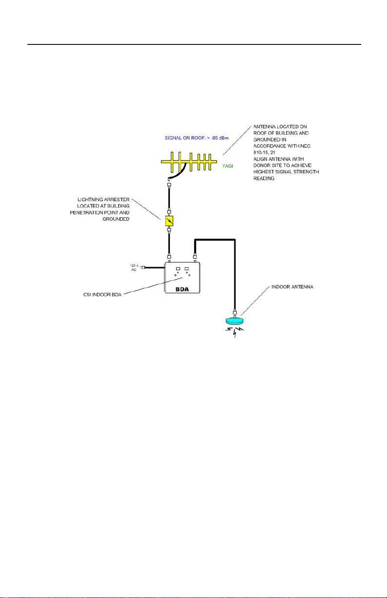
Installation
Example: Standard Single Internal Antenna System Design
Optional Accessories
Accessories are available directly from Cellular Specialties, Inc. or any of
CSI’s distributors.
• Outside High Gain Yagi Antennas
PCS – model number (CSI-AY/1.85-1.99/10)
SMR and Cellular – model number (CSI-AY/806-960/11) and (CSI-AY/806-960/14)
• Inside Omnidirectional Antennas
PCS – model number (CSI-AS/1.85-1.99/2)
SMR – model number (CSI-AS/806-866/4)
Tri-Band – model number ( CSI-AO/800/2.5K/3)
• Power Dividers
2:1 - model number (CSI-S2BSC)
3:1 - model number (CSI-S3BSC)
4:1 - model number (CSI-S4BSC)
• Grounding Kit - model number (CSI-GKIT)
• Lightning Arrestor - model number (CSI-CAP)
• Directional Couplers and Cross Band Couplers are also available
- 4 -
Important Installation Notes
• A high degree of isolation must be afforded to prevent any re-generative
feedBack in the system. FeedBack of this nature causes the amplifier to emit a
continuous signal of maximum amplitude and could, in some cases, interfere with
normal operation of the cell site. The use of window mounts or other non-rooftop
mountings should be avoided.
• The Installer should refer to the Safety Precautions, in the following section, for
proper antenna selection and installation
WARNING! AMPLIFIER OR HANDSET DAMAGE MAY OCCUR IF A
HANDSET IS CONNECTED DIRECTLY TO THE BDA OR THE COAX THAT
LEADS TO THE BDA.
Important Safety Information
For INDOOR
use, an omnidirectional antenna
!
authorized for use with this unit.
Inside antennas must be positioned
to observe minimum separation of
20 cm. (~ 8 in.) from all users and
bystanders. For the protection of
personnel working in the vicinity of
inside (downlink) antennas, the
following guidelines for minimum
distances between the human body
and the antenna must be observed.
The installation of an INDOOR
antenna must be such that, under
normal conditions, all personnel
cannot come within 20 cm. (~ 8.0
in.) from any inside antenna.
Exceeding this minimum separation
will ensure that the employee or
bystander does not receive RFexposure beyond the maximum
permissible exposure according to
section 1.1310 i.e. limits for
General Population/Uncontrolled
Exposure.
with a maximum
gain of 3 dBi is
For OUTDOOR use, a directional
antenna up to a maximum gain of
11dBd is authorized for use with this
unit.The outside antenna must be
positioned to observe minimum
separation of 120 cm. (~ 4 ft.) from
all users and bystanders. For the
protection of personnel working in
the vicinity of outside (uplink)
antennas, the following guidelines
for minimum distances between the
human body and the antenna must
be observed.
The installation of an OUTDOOR
antenna must be such that, under
normal conditions, all personnel
cannot come within 120 cm. (~ 4
ft.) from the outside antenna. In all
installations, the antenna should
never be mounted such that the
main beam is directed toward an
area where workers or bystanders
may be present. Exceeding this
minimum separation will ensure
that the worker or bystander does
not receive RF-exposure beyond
the Maximum Permissible
Exposure according to section
1.1310 i.e. limits for General
Population/Uncontrolled Exposure.
- 5 -
 Loading...