

Westell CSI110-01 Rev C Manual
Cellular Specialties, Inc.
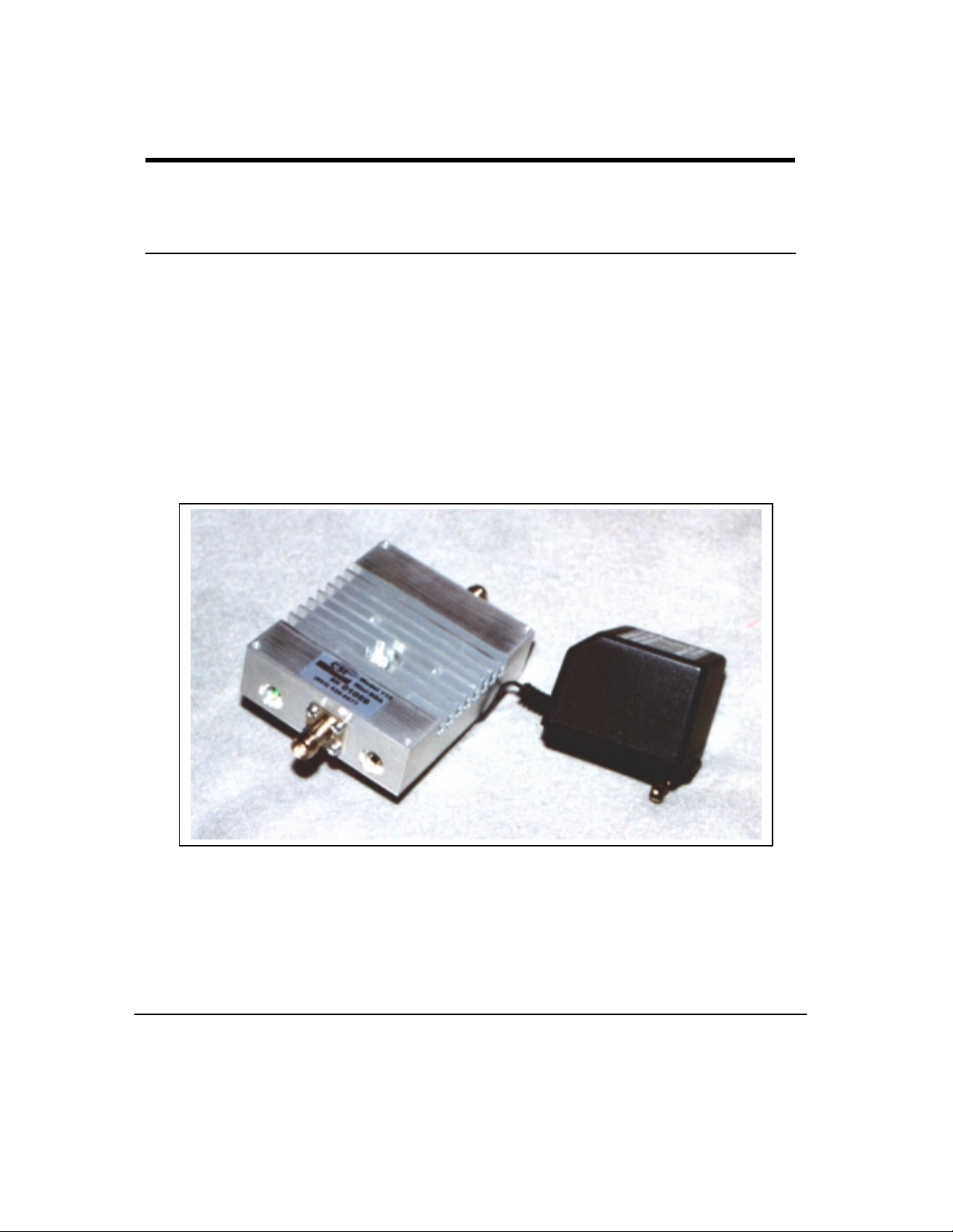
Model 110 Miniature In-Building Amplifier
Operation and Users Manual
1 960-0110-003 Rev C
05/08/01

Table of Contents
1. Product Description
Background
Functional Description
Circuit Description
Functional Block Diagram
Outline Drawing
2. General Specifications
3. Inspection and Installat ion
Inspection of Contents
Package Contents
Installation
Safety
2 960-0110-003 Rev C
05/08/01

1. Product Description
Background
The performance of a cell phone can be easily degraded when in enclosed
structures where signals from a local cell site are not sufficient for reliable
phone operation. The Model 110 Miniature In-Build ing Amplifier (MiniIBA) was developed by Cellular Spec ialties, Inc. (CSI) to enhance cellular
performance within these enclosed structures. Specifically, the Mini-IBA is
designed to cover small areas such as home offices, small workshops, etc.
Functional Description
The Mini-IBA boosts the cellular performance by providing amplification of
both transmit and receive signals. The unit receives the portable phone’s
signal through an inside antenna, amplifies it and then sends it to an outside
antenna. This signal is referred to as the “Uplink”. The Mini-IBA also
receives signals from the Cell Site base station through the outs ide antenna.
This signal is amplified and re-rad iated to the portable phone and is referred
to as the “Downlink”. It is necessary that sufficient signal be available at the
outside antenna.
The outside antenna is usually a directional type such as a “Yagi”, however
an Omni-directional antenna may be used when the structure is located in
close proximity to one or m ore cell sites. Inside antennas are usually Omnidirectional a lthough other types, such as low profile wa ll or ceiling mount,
may be used for special installations.
As shown in Figure 1, there are 2 stages of RF gain in both the Downlink
and Uplink for maximum gains of 30 dB and 40 dB respectively. The
maximum linear output power for the Uplink is 300 milli-Watts and 25
milli-Watts for the Downlink.
An LED indicator on the unit shows the application of power.
3 960-0110-003 Rev C
05/08/01
 Loading...