

Westell BDA510 S8 User Manual

PRODU
CT
M
A
N
UAL
Bi-directional Amplifiers
510 and 610 Series
WESTELL.COM
©Westell Technologies. 960-1032-MNL
rC

Bi-directional Amplifiers
510 and 610 Series
Disclaimer
All information and statements contained herein are accurate to the best of the knowledge of Westell, but Westell
makes no warranty with respect thereto, including without limitation any results that may be obtained from the
products described herein or the infringement by such products of any proprietary rights of any persons. Use or
application of such information or statements is at the users’ sole risk, without any liability on the part of Westell.
Nothing herein shall be construed as license or recommendation for use, which infringes upon any proprietary rights
of any person. Product material and specifications are subject to change without notice. Westell’s standard terms
of sale and the specific terms of any particular sale apply.
. STATE DEPARTMENT EXPORT AUTHORIZATION REQUIRED FOR DISTRIBUTION TO FOREIGN DESTINATIONS OR FOREIGN PERSONS
This document contains Technical Data controlled under the US International Traffic in Arms Regulations (ITAR), 22 CFR 120-130, and may not be exported or transferred
to any Foreign Person, foreign country or foreign entity, by any means, without prior written approval from the U.S. Department of State, Directorate of Defense Trade
Controls (“DDTC”) and DRS ICAS, LLC.
WESTELL.COM
© 2015 Westell Technologies 30 September 2015 Doc. No. 960-1032-MNL rC
1.877.844.4274 Page 2 of 28

Bi-directional Amplifiers
510 and 610 Series
TABLE OF CONTENTS
Disclaimer ........................................................................................................................................................................................................ 2
Preface ........................................................................................................................................................................... 6
Purpose............................................................................................................................................................................................................. 6
Application ...................................................................................................................................................................................................... 6
Product Registration Information .......................................................................................................................................................... 6
Safety Guidelines .......................................................................................................................................................................................... 6
Important Safety Information .................................................................................................................................................................. 7
1 Overview ............................................................................................................................................................... 8
1.1 Product Information ..................................................................................................................................................................... 8
1.1.1 Bi-Directional Amplifier Mechanical and Electrical Specifications, 510 and 610 Series 9
1.2 LED Indicators ............................................................................................................................................................................... 10
1.3 Pin-Out Chart ................................................................................................................................................................................ 10
2 Product Appearance .......................................................................................................................................... 11
2.1 Mechanical Drawing, Dual-band BDA ................................................................................................................................ 11
2.2 Mechanical Drawing, Single-band BDA ............................................................................................................................. 12
3 Installation Tips .................................................................................................................................................. 13
3.1 Important Installation Tips ...................................................................................................................................................... 13
3.2 Standard Single Internal Antenna System Design ......................................................................................................... 13
3.3 Troubleshooting .......................................................................................................................................................................... 14
3.4 Optional Accessories ................................................................................................................................................................. 14
4 LCD Command Interface ................................................................................................................................... 15
4.1 Command Interface Overview ............................................................................................................................................... 15
4.2 The View Menu Series ............................................................................................................................................................... 15
4.2.1 Screen Saver Display 17
4.2.2 Power Readings Display 17
4.2.3 Event Readout Displays 18
4.2.4 Peak Power Readout Display 19
4.2.5 Gain Display 19
4.2.6 BDA Name and Address Display 19
4.3 The Edit Menu Series ................................................................................................................................................................. 21
WESTELL.COM
© 2015 Westell Technologies 30 September 2015 Doc. No. 960-1032-MNL rC
1.877.844.4274 Page 3 of 28

Bi-directional Amplifiers
510 and 610 Series
4.3.1 Edit Events Display 22
4.3.2 Edit Peak Power Readout Display 22
4.3.3 Edit Downlink Gain Display 22
4.3.4 Edit Uplink Gain Display 23
4.3.5 Edit BDA Name Display 23
4.3.6 Edit BDA Address Display 24
4.3.7 Software Shutdown Display 25
4.3.8 Create New Password Display 25
5 Registration Numbers ....................................................................................................................................... 27
Appendix A Glossary ............................................................................................................................................ A
TABLE OF FIGURES
Figure 1-1: Product Registration Information ............................................................................................................................................. 6
Figure 2-1: Mechanical Drawing of the Dual-band BDA, including the FCC label ..................................................................... 11
Figure 2-2: Mechanical Drawing of a Single-band BDA, including FCC label .............................................................................. 12
Figure 3-1: Standard Single Internal Antenna System Design ........................................................................................................... 13
Figure 4-1: View Menu Series .......................................................................................................................................................................... 16
Figure 4-2: Screen Saver Display .................................................................................................................................................................... 17
Figure 4-3: Power Readings Display ............................................................................................................................................................. 17
Figure 4-4: Events Readout Displays ............................................................................................................................................................ 18
Figure 4-5: Peak Power Readout Display .................................................................................................................................................... 19
Figure 4-6: Gain Display ..................................................................................................................................................................................... 19
Figure 4-7: BDA Name and Address Display ............................................................................................................................................. 20
Figure 4-8: Password entry display................................................................................................................................................................ 20
Figure 4-9: Edit Menu Series ............................................................................................................................................................................ 21
Figure 4-10: Edit Events Display ..................................................................................................................................................................... 22
Figure 4-11: Edit Peak Power Readout Display ........................................................................................................................................ 22
Figure 4-12: Edit Downlink Gain Display ..................................................................................................................................................... 23
WESTELL.COM
© 2015 Westell Technologies 30 September 2015 Doc. No. 960-1032-MNL rC
1.877.844.4274 Page 4 of 28

Bi-directional Amplifiers
510 and 610 Series
Figure 4-13: Edit Uplink Gain Display ........................................................................................................................................................... 23
Figure 4-14: Edit BDA name display menu................................................................................................................................................. 24
Figure 4-15: Example display when editing the BDA Name ................................................................................................................ 24
Figure 4-16: Another display when editing the BDA Name ................................................................................................................ 24
Figure 4-17: Edit BDA Address Display ........................................................................................................................................................ 24
Figure 4-18: Software shutdown display ..................................................................................................................................................... 25
Figure 4-19: Old password display ................................................................................................................................................................ 25
Figure 4-20: New password display .............................................................................................................................................................. 26
TABLE OF TABLES
Table 1-1: Model Type/Band Combinations/ Gain Values ..................................................................................................................... 9
Table 1-2: Maximum Power Output (dBm) by Model.............................................................................................................................. 9
Table 1-3:
General
Specifications*
................................................................................................................................................................. 9
Table 1-4: Pin-Out Descriptions ..................................................................................................................................................................... 10
Table A-1: Acronyms and Abbreviations ....................................................................................................................................................... A
WESTELL.COM
© 2015 Westell Technologies 30 September 2015 Doc. No. 960-1032-MNL rC
1.877.844.4274 Page 5 of 28
Bi-directional Amplifiers
510 and 610 Series
Preface
Purpose
The purpose of this document is to provide instructions to help the experienced technician/engineer install and
commission an in-building wireless enhancement system using Westell Technologies Bi-Directional Amplifiers.
Following the procedures outlined will minimize risks associated with modifying a live system and preclude service
interruptions. This document assumes the technician/engineer understands the basic principles and functionality
involved with repeater and in-building systems and addresses the practical concerns of the installation procedure.
Application
Apply this guide whenever a need exists to add enhanced signal capability to an existing system or when the repeater
is being included in a new installation.
Product Registration Information
The serial number is located on the label on the bottom panel, near the power connectors. Write this number in the
boxes shown in Figure 1-1. Retain this manual, along with proof of purchase, to serve as a permanent record of your
purchase.
Figure 1-1: Product Registration Information
Safety Guidelines
The general safety information in this guideline applies to both operating and service personnel. Specific warnings
and cautions are located in other parts of this manual where they apply, but may not appear in this summary. Failure
to comply with these precautions or specific warnings elsewhere in the manual violates safety standards of design,
manufacture, and intended use of equipment. Westell assumes no liability for the customer’s failure to comply with
these requirements:
Grounding: This bi-directional amplifier is designed to operate from 100-240 VAC and should always be
operated with the ground wire properly connected. Do not remove or otherwise alter the grounding lug on
the power cord.
Explosive atmospheres: To avoid explosion or fire, do not operate this product in the presence of flammable
gases or fumes.
Lightning danger: Do not install or adjust this unit during an electrical storm. Use of a suitable lightning
arrester, such as Westell’s model number CSI-CAP, is strongly recommended.
WESTELL.COM
© 2015 Westell Technologies 30 September 2015 Doc. No. 960-1032-MNL rC
1.877.844.4274 Page 6 of 28

Bi-directional Amplifiers
510 and 610 Series
There are no user-serviceable parts inside. Hazardous voltages are present when the cover is removed. Opening
the chassis will void your warranty. If you suspect a malfunction with this product, call your dealer or Westell’s
Technical Support line at 1-877-844-4274. It is recommended that the unit be powered down when connecting and
disconnecting cables.
Important Safety Information
An omni-directional antenna with a maximum gain of 3 dBi is authorized for indoor use with this unit. Inside antennas
must be positioned to observe minimum separation of 20 cm (~8 in) from all users and bystanders. For the protection
of personnel working in the vicinity of inside (downlink) antennas, the following guidelines for minimum distances
between the human body and the antenna must be observed.
Under normal conditions, no personnel can come within 20 cm (~ 8 in) from any inside antenna during the installation
of an indoor antenna. This minimum separation will ensure that the employee or bystander does not receive RFexposure beyond the maximum permissible exposure according to section 1.1310 i.e. limits for general
population/uncontrolled exposure.
For outdoor use, a directional antenna up to a maximum gain of 11 dBi is authorized for use with this unit. The
outside antenna must be positioned to observe minimum separation of 120 cm (~4 ft) from all users and bystanders.
For the protection of personnel working in the vicinity of outside (uplink) antennas, the following guidelines for
minimum distances between the human body and the antenna must be observed.
The installation of an outdoor antenna must be such that, under normal conditions, no personnel can come within
120 cm (~ 4 ft) from the outside antenna. In all installations, the antenna should never be mounted such that the
main beam is directed toward an area where workers or bystanders may be present. Exceeding this minimum
separation will ensure that the worker or bystander does not receive RF-exposure beyond the maximum permissible
exposure according to section 1.1310 i.e. limits for general population/uncontrolled exposure.
WESTELL.COM
© 2015 Westell Technologies 30 September 2015 Doc. No. 960-1032-MNL rC
1.877.844.4274 Page 7 of 28

Bi-directional Amplifiers
510 and 610 Series
1 Overview
1.1 Product Information
Westell developed the Bi-Directional Amplifier (BDA) for use in enclosed structures where sufficient signal from local
cell sites to operate cell phones was unavailable within the building. Sufficient signal must be available on the roof
of the structure. The BDA is connected to an external antenna, usually on the roof, and to one or more internal
antennas placed strategically throughout the area where phone service is desired.
The external antenna is usually a directional type such as a yagi. Internal antennas are usually omnidirectional,
although various other types may be used for certain installations. The BDA amplifies both the uplink (phone to
tower) and downlink (tower to phone) signals thus facilitating communications to and from the local cell site.
There are seven amplification stages on the downlink and seven on the uplink for a total of 65 to 80 dB nominal gain
for each link. Gain can be set using the LCD display and pressing the up and down buttons. There are also LED
indicators on the top cover for power overload and gain reduction to prevent oscillation.
WARNING FOR PUBLIC SAFETY MODELS
The bi-directional amplifier (BDA) is not a consumer device. This product is
designed for installation by FCC licensees and qualified users. You must have an
FCC LICENSE or express consent of an FCC Licensee to operate this device. You
must register class B signal boosters (as defined in 47 CFR 90.219) online at
www.fcc.gov/signal-boosters/registration. Unauthorized use may result in
significant forfeiture penalties, including penalties in excess of $100,000 for each
continuing violation.
WESTELL.COM
© 2015 Westell Technologies 30 September 2015 Doc. No. 960-1032-MNL rC
1.877.844.4274 Page 8 of 28
Bi-directional Amplifiers
Model
51062/51065
51075
51080
61080
Single Band
C, PS7, PS8, P
C, PS7, PS8, P
PS8
C,
PS8,P
Dual Band
C/P, PS8 /S9
C/P, PS8 /S9
-
C/P, P/P, P/S9
Gain (dB)
65 75 80 80
Maximum Power Output (dBm)
Band
Designation*
Frequency Band
51062/065/075
51080
61080
C
Cell
27
-
30 PS7
SMR 700
27 26
29
PS8
SMR 800
27
-
26
P
PCS 22
-
26
S9
SMR 900
27
-
-
Noise Figure, Typical (dB)
5.5
AGC
(dB)
25
Gain Adjustment Range (dB)
0-30, 1 dB
steps
Propagation Delay (nS)
<250
Maximum Input Power (dBm)
+10
Connectors
N-Female
Temperature (F)
-22 to
+118
Dimension (Inches) (Single Band)
12.38 x 12.6 x
6.21
Dimension (Inches) (Dual Band)
16.6 x 17.88 x
7.67
Weight (lbs) (Single Band)
15.5
nominal
Weight (lbs) (Dual Band)
19.
nominal
Power R
equire
d
120 VAC @ 1.3
A
510 and 610 Series
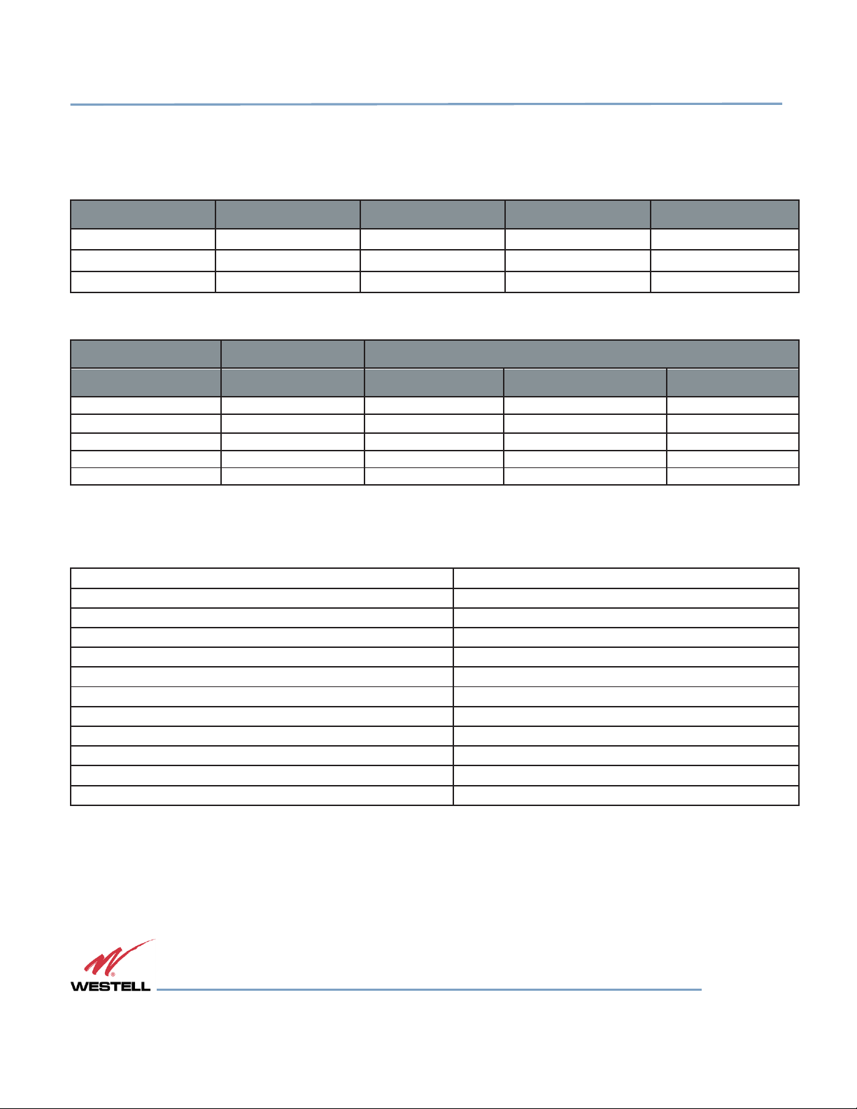
1.1.1 Bi-Directional Amplifier Mechanical and Electrical Specifications, 510 and 610 Series
Table 1-1: Model Type/Band Combinations/ Gain Values
Table 1-2: Maximum Power Output (dBm) by Model
*Refers to available band combinations by model (Table 1-1).
*
Applicable
to models listed in
Table 1-1
and
Table 1-3:
Table 1-2
General
.
Specifications*
WESTELL.COM
© 2015 Westell Technologies 30 September 2015 Doc. No. 960-1032-MNL rC
1.877.844.4274 Page 9 of 28
 Loading...