

Westell AWC‐TMAV‐850‐FB Installation Manual
R
030‐300302 Rev A, December 2013
Equipment Issue 1
‐ Installation Guide ‐
Westell AWC‐TMAV‐850‐FB Tower Mounted Amplifier
Section AWC‐TMV‐850‐301
1. GENERAL
1.1 Document Purpose
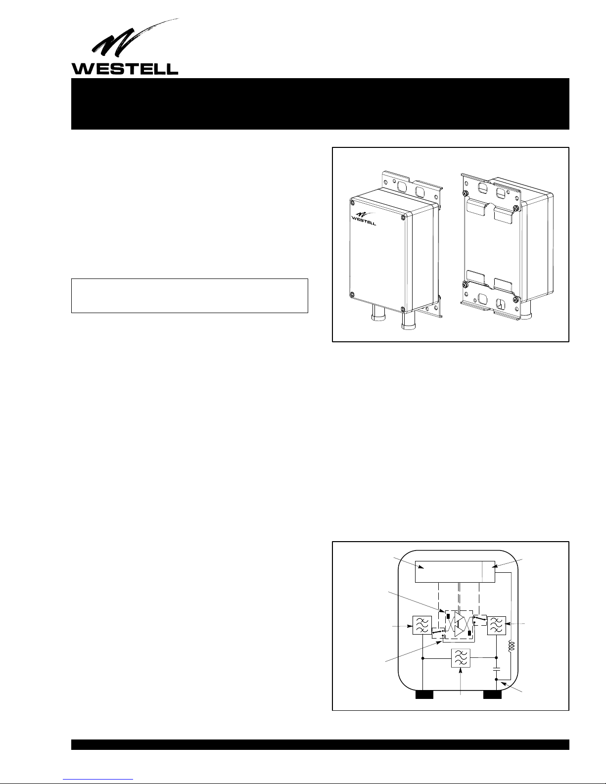
This document provides installation and specification information
on Westell's AWC‐TMAV‐850‐FB 850 MHz Full Band Tower
Mounted Amplifier (TMA). A Westell AWC‐TMAV‐850‐FB
TMA is shown in Figure 1. See Table 1 for ordering information.
1.2 Document Status
Whenever this document is updated, the reason will be stated in
this paragraph.
‐ NOTE ‐
Hereafter, the AWC‐TMAV‐850‐FB Tower Mounted Amplifier may
be referred to as the “TMA.”
1.3 Product Purpose & Description
Westell's TMA's are costeffective tools to extend cell site cover
age and improve cell site capacity by conditioning and
amplifying the user‐endpoint uplink signal in an LTE radio ac
cess network. Westell's TMAs can be used in any application
which requires improved receiver sensitivity of the BTS/eN
odeB.
1.4 Product Mounting Location
The TMA is typically installed on a cell tower, close to the an
tenna. See Paragraph 3.4 for mounting steps and Figure 6 for
dimensions.
1.5 Product Features
Features of the TMA are shown in the following list.
S Advanced, balanced LNA design with variable gain capability
S Low noise figure, return loss, and bypass insertion loss
S Compact size
Front View
Rear View
Figure 1. Tower Mounted Amplifier (TMA) Unit
2.2 PreLNA Rx BPF
This is the preLNA (Low Noise Amplifier) band pass filter.
This filter conditions the uplink signal from the antenna before
the LNA.
2.3 Balanced Low Noise Amplifier
This is the amplifier of the TMA and includes the bypass cir
cuitry.
2.4 PostLNA Rx BPF
This is the postLNA band pass filter. This filter conditions the
uplink signal to the eNodeB.
2.5 Tx BPF
This is the transmit band pass filter. This filter conditions the du
plexed downlink signal from the eNodeB to the antenna.
S Heavy‐duty top and bottom mounting brackets with various
mounting holes to accept mounting bolts/screws and
mounting straps or bands
S Two, female, 7/16 DIN connectors at the bottom of the unit;
one for antenna connection and one for BTS
S Weather rating of IP67 (temperature range of ‐40_ to +65_C)
2FUNCTIONAL DESCRIPTION
The TMA includes the following functional blocks, as shown in
Figure 2.
2.1 Control, Bias & Alarm Electronics
This block includes the control processor, AISG modem, and
lightning protection.
1312I1RA
Control, Bias &
Alarm Electronics
Balanced Low
Noise Amplifier
Pre-LNA Rx BPF
−
RF Bypass
& Switches
Copyright 2013 Westell, Inc. All rights reserved.
Tx BPF
BTSANTENNA
Figure 2. Block Diagram
Lightning
Protection
Post-LNA
Rx BPF
Bias-T
Page 1 of 6
Section AWC‐TMV‐850‐301
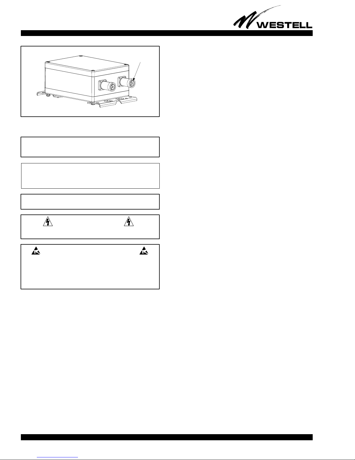
When installing:
Verify connectors are free of debris
Mount TMA so connectors face down
Weatherize connections after connecting cables
Remove caps
Figure 3. Bottom View Showing Connectors
Female
7/16 DIN connector
030‐300302 Rev. A
R
cable. For deployments where the eNodeB provides power, a
CIM is not needed as power is injected onto the center pin of the
RF cable leading to the TMA directly by the eNodeB.
3.2 Verifying Functionality Prior to Mounting
Prior to mounting the TMA on the tower, verify proper opera
tion of the unit by following the steps listed in either Paragraph
3.2.1, 3.2.2, or 3.2.3 below, depending on the powering method.
3.2.1 Powered from the PDU using a CIM
When power is from the Power Distribution Unit (PDU, such as
a Westell AWC‐PDU‐6) using a Current Injector Modem (CIM,
such as the Westell AWC‐CIM+R), follow the steps below.
‐ CAUTION ‐
Improper grounding could be service affecting and cause service
interruptions.
‐ INSPECTION NOTE ‐
Visually inspect the product for damages prior to installation. If
damaged in transit, immediately report the damage to the transporta
tion company and to Westell.
‐ CAUTION ‐
Do not apply power until all connections are complete.
‐ CAUTION ‐
Risk of electric shock. Differential voltages of up to 260V can exist
on telecommunications lines.
CAUTION ‐ STATIC‐SENSITIVE
This product contains static‐sensitive components! Proper
electrostatic discharge procedures must be followed to maintain
personal and equipment safety. Do not store units near magnetic,
electromagnetic or electrostatic fields. Always store or ship units in
the original static‐protective packaging from Westell. Use anti‐static
mats when working on units.
3 INSTALLATION
3.1 Determine Power Options
The AWCTMAV850FB is powered by applying DC voltage to
the center pin of the 7/16 DIN connector labeled BTS. There are
several options for providing the power:
1. Connect the connector labeled `ANT' of the CIM to the
connector labeled `BTS' on the TMA. Note that depending
on the model of CIM used, an adapter may be required.
2. Connect the AISG connector of the CIM power cable to the
CIM. Connect the other end of the CIM power cable to PDU.
3. Connect PDU power cable to appropriate power source as
indicated in the PDU installation documentation.
4. Check TMA functionality by observing the LED's on the
PDU. A red LED indicates the TMA is in alarm.
5. If the TMA is in alarm, verify all connections. If all connec
tions are correct, replace TMA.
3.2.2 Powered from a Westell AISG Controller using CIM
When power is from an AISG Controller (such as a Westell
AISG‐RM3 controller or an AISG‐CNTRL‐A controller kit),
follow the steps below.
1. Connect the connector labeled `ANT' of the CIM to the
connector labeled `BTS' on the TMA. Note that depending
on the model of CIM used, an adapter may be required.
2. Using an AISG cable provided with the AISG controller,
connect the cable to the male AISG connector on the CIM.
Connect the other end of the AISG cable to the AISG con
troller.
3. Using the AISG controller software, verify that the TMA is
operational and that no alarms are present.
4. If alarms are present, verify all connections. If all connec
tions are correct, replace TMA.
S eNodeB
S Westell Power Distribution Unit (e.g., AWCPDU6)
S Westell Rack‐Mount AISG Controller A99AISGRM3
S Westell's A99AISGCNTRLA portable AISG controller
kit to power the TMA for running AISG commands
Westell PDU's and AISG controllers supply the DC voltage to
power the TMA via Westell's Current Injector Modem (CIM).
The CIM injects the DC voltage onto the center pin of its 7/16
DIN connector labeled BTS. To power the TMA, the CIM can
be connected to the TMA or can be connected via an RF jumper
2
3.2.3 Powered from an eNodeB without CIM
Verification of the TMA operation when used with an eNodeB
as the power source is beyond the scope of this document. The
basic steps are shown below:
1. Connect the connector labeled `BTS' on the TMA to the
eNodeB.
2. Power up the TMA using the eNodeB command line inter
face.
3. Check for alarms using the eNodeB command line inter
face.
1312I1RA
 Loading...