

Westell AISG-RM3 User Manual
Section AIS‐RM3‐20B
R
030‐101806 Rev. A, October 2013
Westellr AISG‐RM3 Rack‐Mount, 3‐Port, AISG Controller
CONTENTS PAGE #
1. GENERAL 1....................................
2. FEATURES & OPTIONS 2.......................
3. GETTING STARTED 4..........................
4. CONFIGURING THE AISG‐RM3 6...............
5. USING THE AISG‐RM3 9........................
6. MANAGING ANTENNA CONFIGURATIONS 9.....
7. USING THE CONSOLE INTERFACE 17...........
8. PERFORMING FIRMWARE UPGRADES 17.......
9. ERROR & ALARM CODES/MESSAGES 19........
10. CUSTOMER & TECHNICAL SERVICESRES 19...
11. WARRANTY & REPAIRS 21......................
12. SPECIFICATIONS 21...........................
13. ACRONYMS & ABBREVIATIONS 21..............
1. GENERAL
Hereafter, the AISG‐RM3 may be referred to as the “controller”
or as the “AISG‐RM3.”
1.3 Product Purpose and Description
Westell's AISG‐RM3 Rack Mountable 3‐Port AISG Control
ler is used to control, manage, adjust, monitor, and power a
group of AISG devices such as TMAs and RET antennas. Local
and remote control and management of the devices is provided
via the on‐board Ethernet port and a web interface.
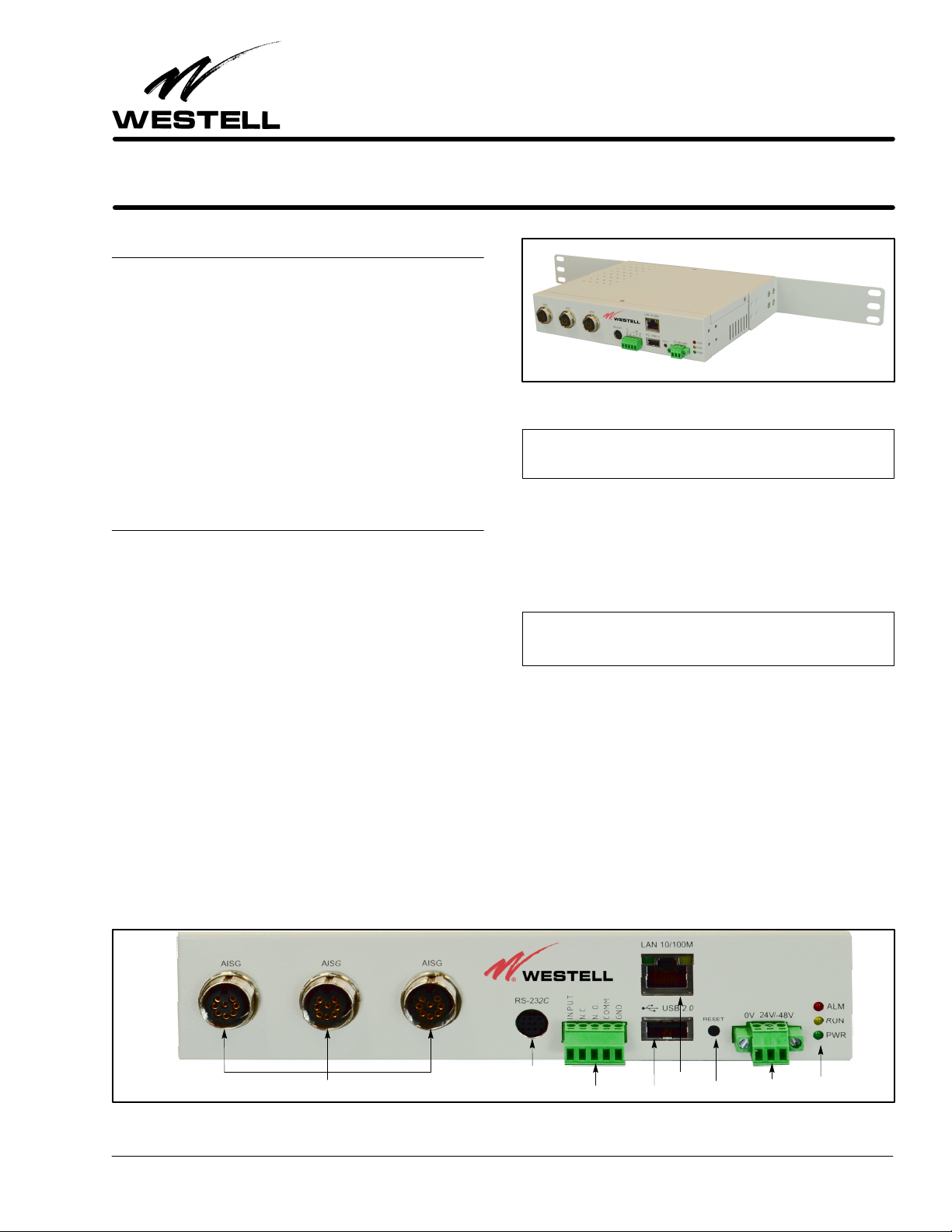
Figure 1. AISG‐RM3 AISG Controller
‐ NOTE ‐
Equipment Issue B
1.1 Document Purpose
This document provides general information, hardware and
software feature descriptions, installation information, as well
as configuration and management information for the Westell
AISG‐RM3 Rack Mountable 3‐Port AISG Controller, a con
troller for AISG Antenna Line Devices (ALD). The AISG‐RM3
is shown in Figure 1, and comes with both rack‐mount and
wall‐mount ears. See Table 19 for ordering information.
1.2 Document Status
Whenever this practice is updated, the reason will be stated here.
This document reflects the Issue B equipment which accepts an
input power supply range of ‐48VDC to +24VDC, and uses con
tact relays as alarm outputs.
‐ LATEST DOCUMENTATION NOTE ‐
Visit www.westell.com for the latest version of this document and
for other product documentation.
1.4 Product Mounting
The AISG‐RM3 can be rack or wall mounted using the provided
mounting ears. It may also be set on a desk or tabletop.
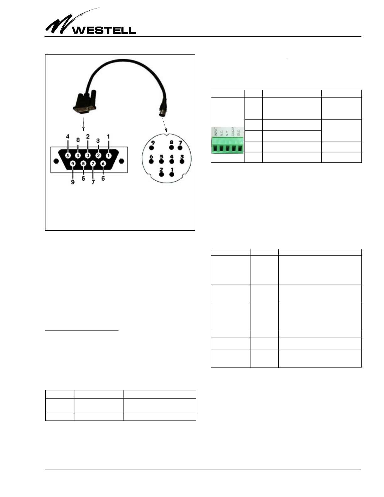
1.5 System Application
The AISGRM3 communicates with Westell's TMA using
AISG protocol. The AISG signals are injected onto and pulled
from the center PIN of the RF feeder cable running to the TMA
using a Current Injector Modem (CIM).
1.6 Product Default Parameters
Please note the default parameters for the controller below:
3 AISG Ports (Female)
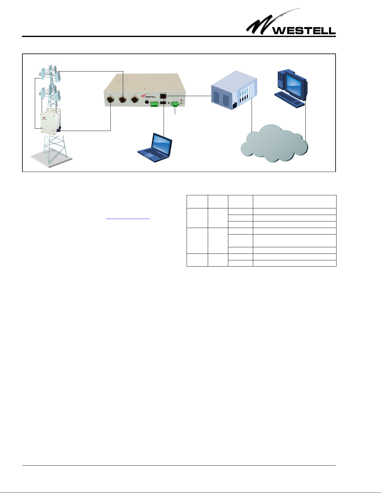
Figure 2. Front View of AISG‐RM3 Controller
ECopyright 2013 EWestell, Inc. All rights reserved. Printed in the United States of America.
Westellr is a trademark of Westell, Inc.
RS‐232 Port
Alarm Contacts
Ethernet
Reset ButtonUSB Port
Power Jack
LEDs
1310IBRA
Page 1 of 22
Section AIS‐RM3‐20B
030‐101806 Rev. A
R
RET Antenna
AISG-RM3 Controller
TMA
Figure 3. AISG‐RM3 Controller Sample Application
Default IP Address: 192.168.0.30
Default User Name: admin Default Password: admin
Latest documentation location: http://westell.com
2. FEATURES & OPTIONS
The features and highlights of the Westell AISG‐RM3 are lis
ted below. See the paragraphs that follow in this section for
additional information on some of the features.
2.1 Highlights and Benefits
Power
Input
Laptop
(on−site
control)
Base Station
LED Color
ALM
(alarm)
RUN Yellow
PWR
(power)
Red
Green
Table 1. LED Conditions and States
Off−site
control
IP Network
State/
Status
Steady AISG RM3 cannot ping default gateway
Flashing Alarm present.
Off No alarm present
Steady AISG RM3 busy
Flashing
Off
Steady On steady when power is present.
Off Unit not powered.
Indicates system is running or ready for
use.
Description
The controller provides the following benefits.
S Supports both AISG v1.1 and AISG v2.0 for remote control
and monitoring of AISG line devices
S Remote setting of TMA gain and mode
S Remote adjustment of RET antenna tilt angle
S RET antenna configuration and calibration
S Management of base station site information such as site
ID, name, location and contact
S Management of user accounts with multiple security levels
S Power saving mode to suspend the power output of AISG port
2.2 Front Panel Features
On the front panel of the controller are eight ports (including
3 AISG ports to connect to AISG line devices), a reset button,
a n d th r e e L E D s, as sh o wn i n Tab l e 1 a n d Tab l e 4 be l o w a n d ex
plained in the paragraphs that follow.
2.2.1 LEDs
Three LEDs are located on the front panel of the AISG‐RM3.
Their states and functions are explained in Table 1.
2.2.2 AISG Ports
Three standard, female, 8‐pin, AISG ports are provided on the
front of the controller. Each AISG port can control up to 8 an
tenna line devices by using daisy‐chained cables.
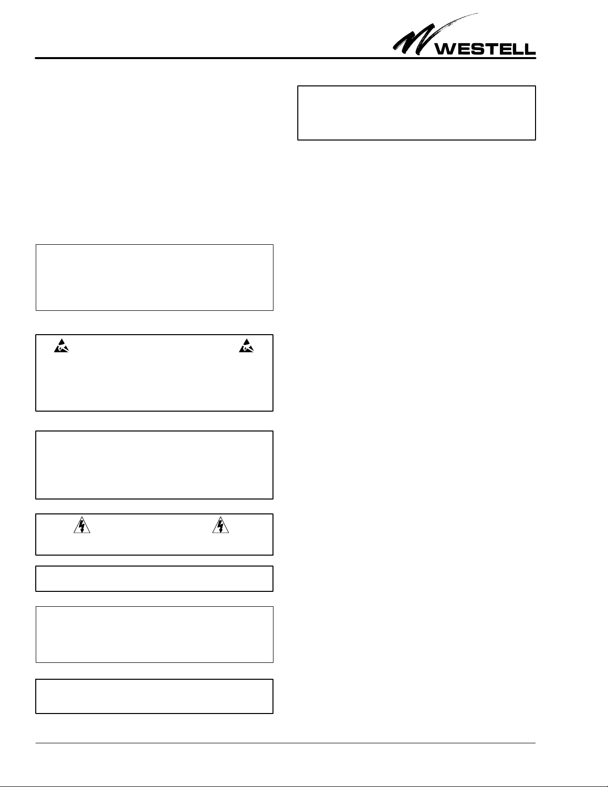
2.2.3 RS‐232 Port
The round RS‐232 port on the controller is used to access the
console or command line interface. See Figure 4 for the
pin‐outs of the DB‐9 RS‐232 connector and for an illustration
of the pin locations. See Part 7 for more information on this in
terface.
2.2.4 Alarm Connector
A pluggable alarm connector is provided for connection with
external alarm reporting equipment. The alarm output is a con
tact relay. Five port holes for stripped wires are provided on the
connector, with screws that accept a small slotted screwdriver
for tightening and securing the alarm wires which are inserted
2
1310IBRA
R
030‐101806 Rev. A
Section AIS‐RM3‐20B
Mates with
connector on
computer
Mates with
connector on
AISG‐RM3
controller
front panel
RS232 Female pin‐out to Mini Din Male pin‐out
Pin 1: Data Carrier Detect Pin 6: Data Set Ready
Pin 2: Receive Data Pin 7: Request to Send
Pin 3: Transmit Data Pin 8: Clear to Send
Pin 4: Data Terminal Ready Pin 9: Ring Indicator
Pin 5: Signal Ground
Figure 4. RS‐232 Cable's Connector Pin‐out
into the port holes (16 ga. max.) This connector is labelled “IN
PUT N.C. N.O. COMM GND”.
INPUT = Digital Input
N.C. = Normally Closed
N.O. = Normally Open
COMM = Communication
GND = Ground
2.2.4.1
Digital Input Contacts
The digital input channel is used to interface a potential free
contact, e.g., a relay. It could be a fire alarm sensor, door sensor,
or failure signal from a power supply in a base station site. The
DI can read the digital input channel status and determine its
alarm state. The INPUT and GND pins are used to make a digit
al input connection.
2.2.4.2
Digital Output Contacts
This module has two relay outputs. The relay outputs are dedic
ated circuits that can be directly connected inline with the
desired control or indicating device.
Connector Label Pin Description Specification
Logical level 0/1.
INPUT Digital Input channel
N.C. Normally Closed relay output
N.O. Normally Open relay output
COMM Common N/A
GND Ground of I/O channels Ground
Max. input DC
+30V, 100mA
Contact Capacity:
AC 125V / 0.5A
DC 24V / 1A
Table 3. Alarm Connector Pin‐outs
2.2.5 Ethernet Port
An Ethernet port labelled “LAN 10/100M” is provided on the
front of the controller.
This port is used to provide access to the
web‐based user interface either by connecting directly to a local
PC or to a router for remote access.
2.2.6 USB Port
A USB port labelled “USB 2.0” on the front of the controller
is reserved for future expansion.
Port Label Type Description
3 AISG ports provided, each Standard
AISG
RS‐232
INPUT
N.C.
N.O.
COMM
GND
LAN 10/100M RJ45 Used to connect to a PC or a network
USB 2.0
24V ‐48V
8‐pin
female
9‐pin,
round,
female
5‐pin
pluggable
USB 2.0,
female
3‐pin
pluggable
Table 4. Front Panel Ports and Connectors
AISG 8pin female IEC 601309 bias/
RS485, connects to an antenna line
device (RET or TMA). Each can control up
to 8 daisy‐chained antenna line devices.
1 RS‐232 port, used to connect to serial
port of a PC for console access
Alarm Connector, 5 wire port holes, screw
down type, accepts 16 gauge wire (max.)
Not used, reserved for future use.
Power connector, 3 wire port holes,
screw down type, accepts 16 gauge wire
(max.), used to connect to power source
Pin Label Description Specification
INPUT Digital Input Channel Logical level 0/1.
Max. Input DC +30V, 100mA
GND Ground of I/O Channels Ground
Table 2. Digital Input Contacts
The DI alarm settings are configured in the System Setting
menu.
1310IBRA
2.2.7 Reset Button
A recessed reset button is provided on the front of the control
ler to perform a hard power‐on reset. Press the button
momentarily to restart the AISG‐RM3 controller. Press and
hold the button for approximately 6 seconds to restore network
settings to the factory default.
2.2.8 Power Connector
A 3‐port pluggable power connector is provided on the front of
the controller to power the unit. The input voltage range for the
3
Section AIS‐RM3‐20B
030‐101806 Rev. A
R
AISG‐RM3 is ‐48VDC to 24VDC, and the unit is polarity in
sensitive.
3. GETTING STARTED
Installation consists of unpacking the equipment to verify all
equipment ordered was received, inspecting the equipment for
damages, following proper safety precautions, gathering tools
and materials that will be needed, mounting or installing the
AISG‐RM3, connecting all cables to the AISG‐RM3, and set
ting up computer communication with the AISG‐RM3. The
following paragraphs provide detailed instructions for perform
ing these procedures.
‐ INSPECTION NOTE ‐
If not previously inspected at the time of delivery, visually inspect
the unit for damages prior to installation. If the equipment has
been damaged in transit, immediately report the extent of the
damage to the transportation company and to Westell (see Part
10 for telephone number).
CAUTION ‐ STATIC‐SENSITIVE
This product contains static‐sensitive components! Proper
electrostatic discharge procedures must be followed to
maintain personal and equipment safety. Do not store units
near magnetic, electromagnetic or electrostatic fields. Always
store or ship units in the original static‐protective packaging
from Westell. Use anti‐static mats when working on units.
‐ CAUTION ‐
Use care when connecting cables and wires, do not force a cable
or wire into place. If a cable or wire resists insertion, remove it
and check for obstructions in or near the connector's slots and
port holes.
3.1 Gathering Tools and Supplies
The following tools and supplies may be needed to physically
install the AISG‐RM3 controller.
Tools/Materials Needed to Physically Install the Controller
- Standard installation tools, including: wrenches, screw
drivers, power drill and bits, wall mount screws, cable ties,
as needed
- Alarm and power cables/wires of sufficient length to extend
from the AISG‐RM3 to the power source and alarm device
(two 22' cables included)
- AISG cables of sufficient length to extend from the
AISG‐RM3 to the antenna line device (three 22' Y‐cables
included)
- Wire strippers and wire cutters
- Any needed cable management equipment/materials
3.2 System/Computer Connection Requirements
To connect and network the controller with a computer, the fol
lowing items/requirements are needed:
‐ PRECAUTIONARY STATEMENT ‐
‐ This equipment is intended to be used behind devices that
provide primary lightning protection.
‐ This installation should conform to Local Codes and NEC
requirements.
‐ This equipment is to be installed in a restricted access location.
CAUTION
Risk of electric shock. Differential voltages of up to 60V can exist
on the bias or telecommunications lines.
‐ CAUTION ‐
Never apply power until all installer connections are made.
‐ GROUNDING NOTE ‐
Always follow the National Electrical Code (NEC) rules, local safety pre
cautions, and standard operating procedures for grounding the equipment
when installing, upgrading, repairing or maintaining equipment. Any in
structions or information contained herein is subordinate to local codes,
operating procedures or practices.
‐ CAUTION ‐
Improper grounding could be service affecting and cause
service interruptions.
1. Internet Explorer 6.0 or other web browser
2. Screen resolution of 1024 x 768, or greater
3. A user name and password (see Paragraph 3.6)
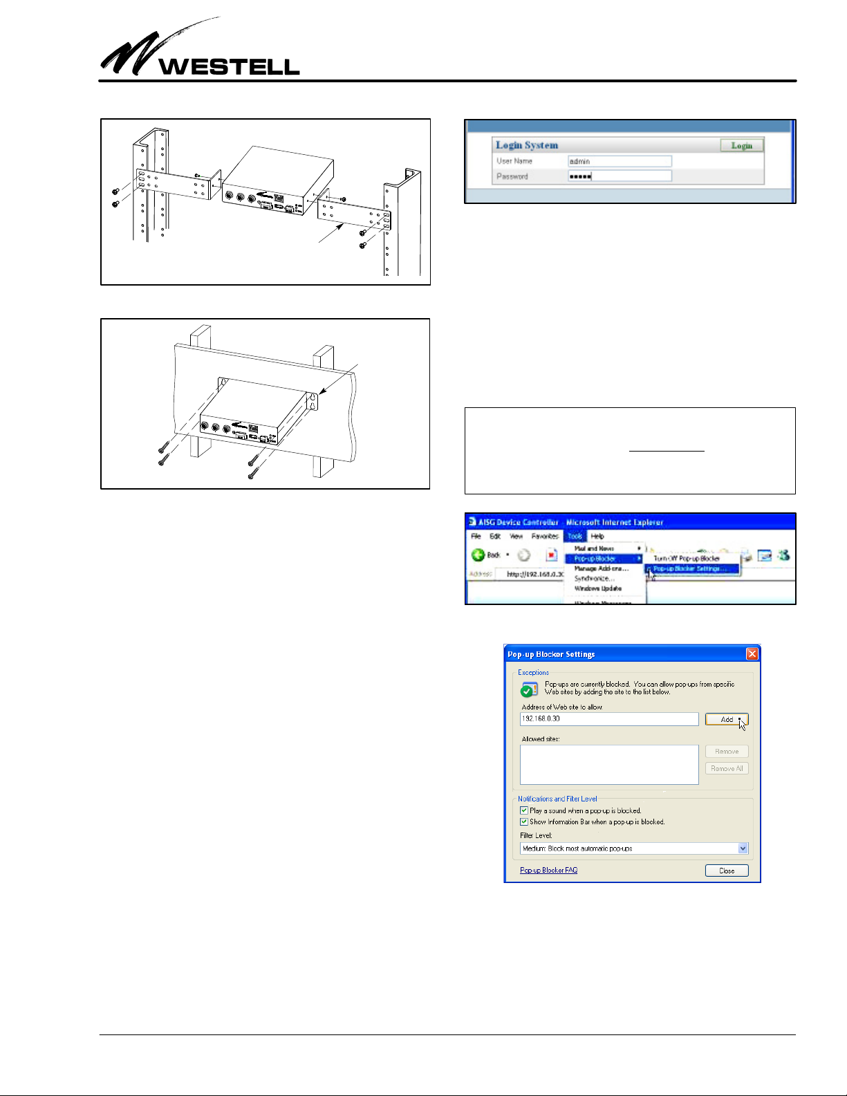
3.3 Mounting the AISG‐RM3 Controller
Each Westell AISG‐RM3 comes with mounting brackets for
rack or wall mounting. The longer brackets are used to mount
the unit in an equipment rack (rack‐mount screws included).
The two short brackets are used to mount the unit on a wall.
Use appropriate wall‐mount screws per the wall type and com
pany practices.
3.4 Connecting Cables to AISG‐RM3
Follow the steps below to make all cable connections to the
AISG‐RM3.
1. Connect the Ethernet port on the controller to a local PC
using a standard Ethernet cable.
2. For use with Westell TMA's, connect one of the AISG fe
male ports on the controller to a Current Injector Modem
using one of the supplied AISG Ycables.
3. Repeat the step above for all antenna line devices (RET or
TMA).
4
1310IBRA
R
030‐101806 Rev. A
AISG‐RM3
Section AIS‐RM3‐20B
Figure 7. Login Screen
Long L‐brackets for rack mounting
Figure 5. Rack Mounting
Short flat brackets
for wall mounting
Figure 6. Wall Mounting
4. Connect DC power to the power port on the controller. The
power LED indicator should light up and the controller
should start to boot. Wait for the RUN LED to blink which
indicates that the controller is ready for use.
5. For optional console access, connect the RS232 port on the
controller to the PC using a DB‐9 to mini‐DIN conversion
cable (not provided, shown in Figure 4).
2. Login to the controller. At the Login System screen, enter
the user name and password:
User Name = admin
Password = admin
These are default values. This user account is the default
system administrator account which has full access permis
sions. You should change the password of the default
administrator account after you first log in. You should cre
ate other accounts for doing general operations.
‐ BROWSER POP‐UP BLOCKING WARNING‐
The webbased interface makes use of popup windows to display
messages. If your browser has the popup blocking
then you may not see all of the messages. You may either: A) turn off
the blocking of popups, or B) configure the blocking to allow popups
that originate from the Westell AISG‐RM3 controller’s IP.
feature turned on,
Figure 8. Locating the Pop‐up Blocker Tool
3.5 Setting the IP Address / Networking
The AISG‐RM3 controller has been factory preset with an IP
address of 192.168.0.30. In order to access the AISG‐RM3 con
troller from a PC connected directly by an Ethernet cable, the
PC’s IP address must belong to the same network.
3.6 Accessing / Logging In to the Controller
To access the AISG‐RM3 controller, you need to first log in.
1. Address the controller. From your PC, launch Internet Ex
plorer and type the IP address of the AISG‐RM3 controller
in the Address Bar.
http://<IP address of AISG‐RM3>
The default IP address of the controller has been preset to
192.168.0.30. Enter this IP address for first‐time access. It
can be changed later. The browser should display the Login
page as shown in Figure 7.
1310IBRA
Figure 9. Configuring Pop‐up Blocker Tool
3. Skip to Part 4 or Log out. Skip to Part 4 if configuration is
desired at this time. If configuration and management will
take place at a later time, log out of the system. Click on the
Logout tab near the top right of the screen (see Figure 10)
to log out from the controller.
5
Section AIS‐RM3‐20B
030‐101806 Rev. A
R
_ Site Information _ Logout
_ System Setting
Figure 10. Logging Out
See Part 7 for information on console access.
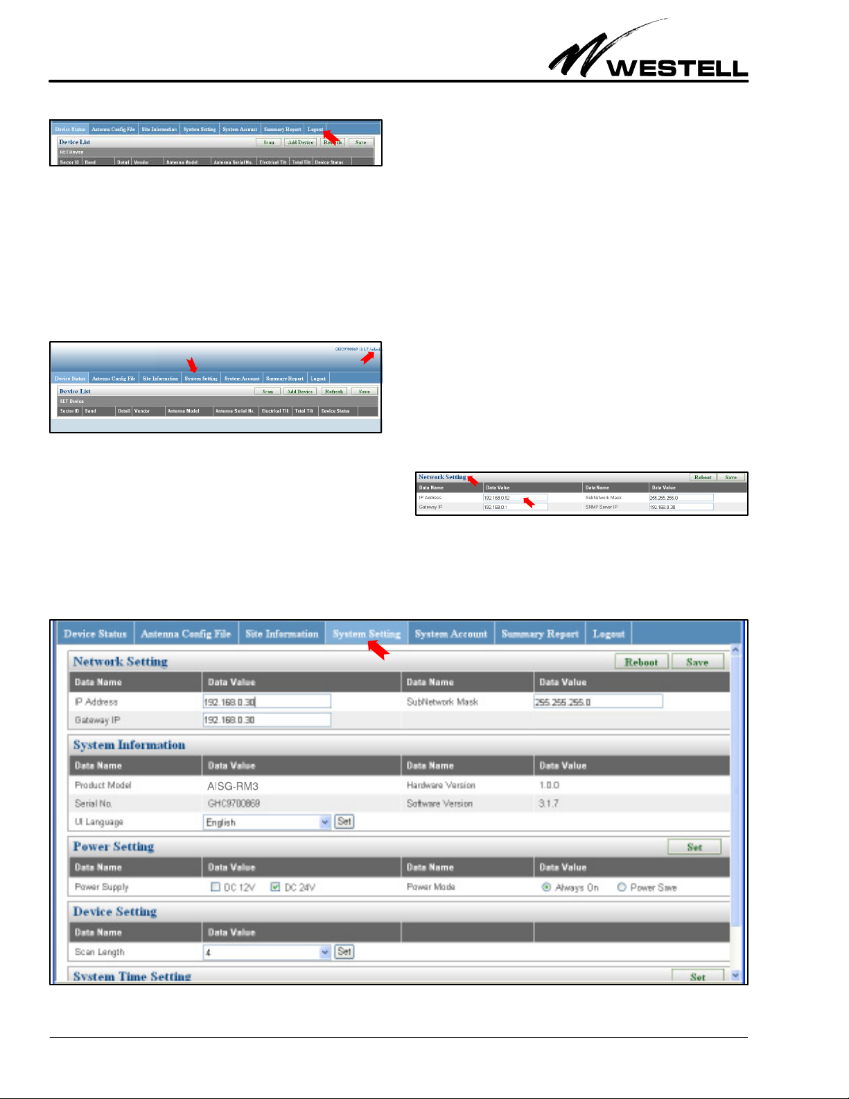
4. CONFIGURING THE AISG‐RM3
In this section, configuring the system settings and managing
user accounts are explained. If not already logged in, log in to
the system as explained in Paragraph 3.6. After you log in, the
main menu screen (Figure 11) is displayed.
Menu tabs in top row
Figure 11. Main Menu Screen
In the upper right corner, the current user name is displayed. It
is “admin” in this case (see red arrow). Menu names are dis
played as “tabs” in the first row near the top of the main menu.
The available menus are:
_ Device Status _ System Account
_ Antenna Config File _ Summary Report
Current user name
4.1 Configure the System Settings
Click on the System Setting tab (as shown in Figure 11) to open
the System Setting menu. The System Setting menu (Figure 12)
which appears is further divided into five sections or panels:
Æ Network Setting (see Paragraph 4.1.1)
Æ System Information (see Paragraph 4.1.2)
Æ Power Setting (see Paragraph 4.1.3)
Æ Device Setting, (see Paragraph 4.1.4) and
Æ System Time Setting (see Paragraph 4.1.5)
4.1.1 Network Settings
The Network Setting section is where the values for IP address,
SubNetwork Mask, and Gateway IP can be changed. Obtain the
new IP for the AISG‐RM3 controller from the site network ad
ministrator. In this example, the settings are:
AISG‐RM3 IP: 192.168.0.92
Gateway IP: 192.168.0.1
Figure 13. Network Settings
The data fields are explained in Table 5.
Æ
Æ
Æ
Æ
Æ
Figure 12. System Setting Screen
6
1310IBRA
R
030‐101806 Rev. A
Section AIS‐RM3‐20B
Field Name Description / Options
IP Address Change to the new IP address assigned to the AISG‐RM3
SubNetwork
Mask
Gateway IP Change to the new Gateway IP used at the site network.
controller at the site network.
Change to the new SubNetwork Mask used at the site net
work.
Table 5. Network Settings / IP Address Fields
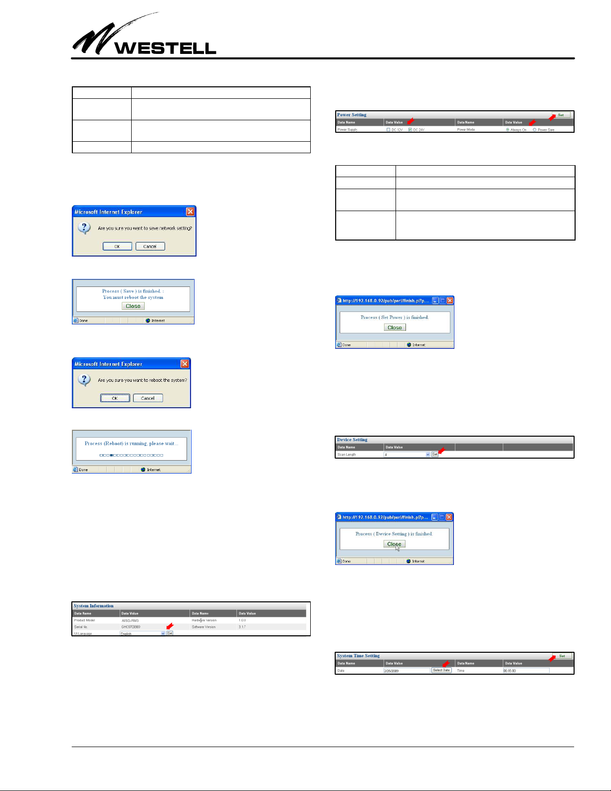
Click on the Save button in the upper right corner once you have
finished changing the values. An alert window appears.
Click on the OK button to confirm the save.
After saving, the new settings will only take effect after the sys
tem is rebooted. Click the Reboot button to reboot the system.
ring to Table 6 as needed, then click on the Set button to apply
the changes.
Figure 15. Power Setting Area
Field Name Description / Options
Power Supply DC 12V or DC 24V. Check to select the proper voltage.
Power Mode:
Always On
Power Mode:
Power Save
Check to supply power continuously.
This is a power saving mode. Check to supply power only
when a command is initiated; otherwise power is not sup
plied.
Table 6. Power Setting Fields
When the Set Power process is completed, the following popup
window is displayed. Click on the Close button to close it.
4.1.4 Device Setting
Click OK to confirm and initiate the reboot process.
Wait for the process to end. You may need to reconnect to the
AISG‐RM3 using the new IP if the IP is changed.
4.1.2 System Information and Language
The System Information section (see Figure 12 or Figure 14)
shows the Product Model, Serial No., Hardware Version and
Software Version of the AISG‐RM3 system. The desired user in
terface language can also be changed here. Select the preferred
language from the dropdown list and click the Set button to ap
ply the change.
Figure 14. System Information Area
4.1.3 Power Setting
In the Power Setting section (Figure 15), the power voltage and
power supply mode provided to the connected AISG devices can
be changed. Change the settings per company practice, refer
In the Device Setting section, select the Scan Length value used
when scanning for devices. The default value is 4. This value can
be increased if a connected device is not being distinguished
from another during a scan.
Figure 16. Device Setting Area - Scan Length
Click on the Set button to apply the changes. Click on the Close
button when the process is finished.
4.1.5 System Time Setting
The System Time Setting section is used to set the system date
and time. The date uses the mm/dd/yyyy format. By clicking on
the Select Date button, a calendar popup appears which can be
used to select the date. The time setting uses the 24hour format.
Figure 17. System Time Setting Area - Date Format
Click on the Set button to apply the changes. Click on the Close
button when the process is done.
1310IBRA
7
 Loading...