

Westell A90WMT-00 User Manual
Draft 1 - 07/11/06
User Guide
require the name for
identification purposes.
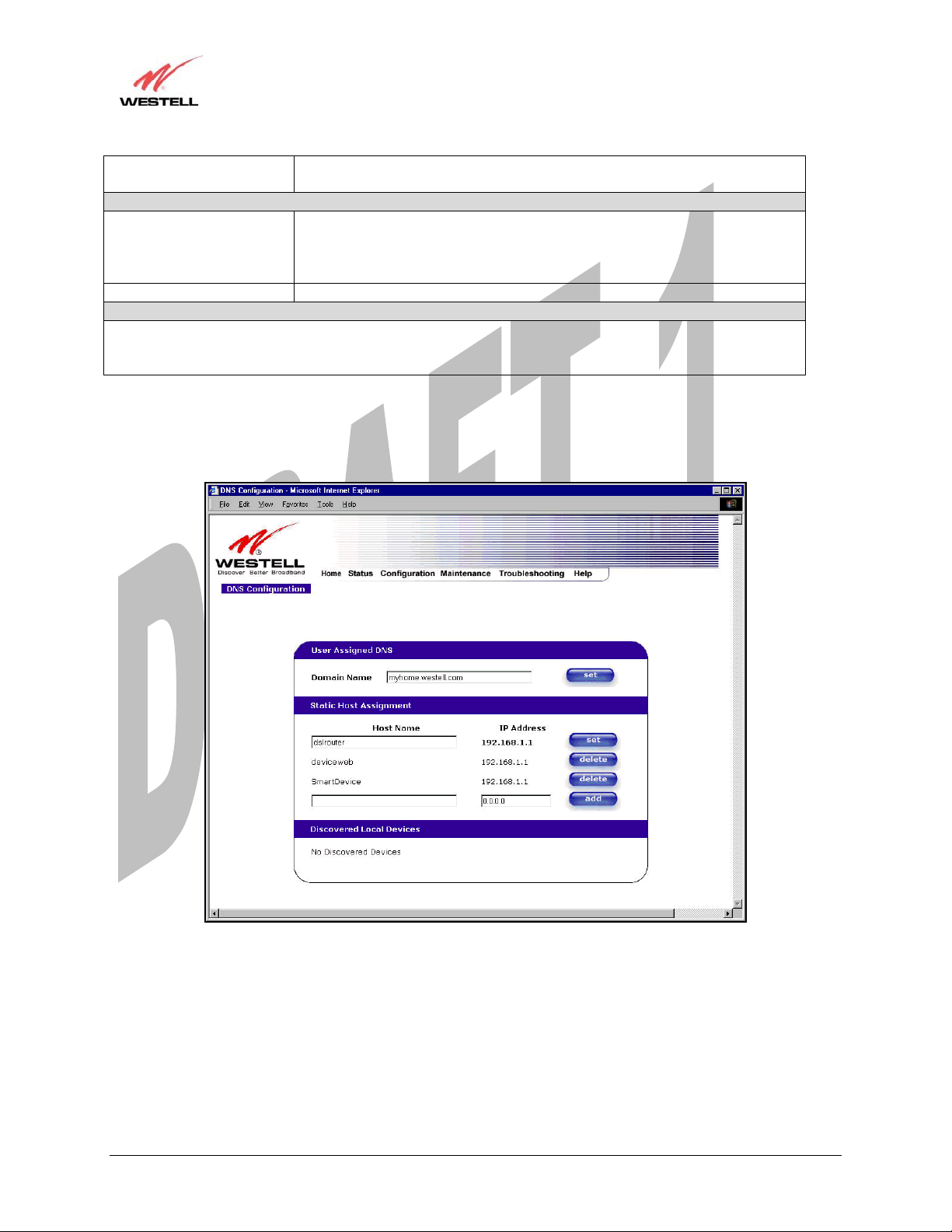
Host Name This field allows you to enter a HOST name for the Media Gateway.
IP Address Displays the IP address that is assigned to the Host Name.
This field displays a list of the computers on the LAN that were assigned a DHCP Address. The DNS name
and IP address entry of each discovered device is displayed. (NOTE: The values in this field will be displayed
barring any propagation delays. If ‘No Discovered Devices’ is displayed, manually refresh the screen.)
If you want to add a new Host Name and IP address to your DNS server, enter the Gateway’s Host Name and IP
Address in the fields provided in the Static Host Assignment section.
new domain name and click Set.
Static Host Assignment
To add a new Host name, in the field under Static Host Assignment, type in the
Host Name and the IP address and click Set.
Discover Local Devices
Media Gateway (Model WMT)
030-300417 Rev. A 61 July 2006
Draft 1 - 07/11/06
User Guide
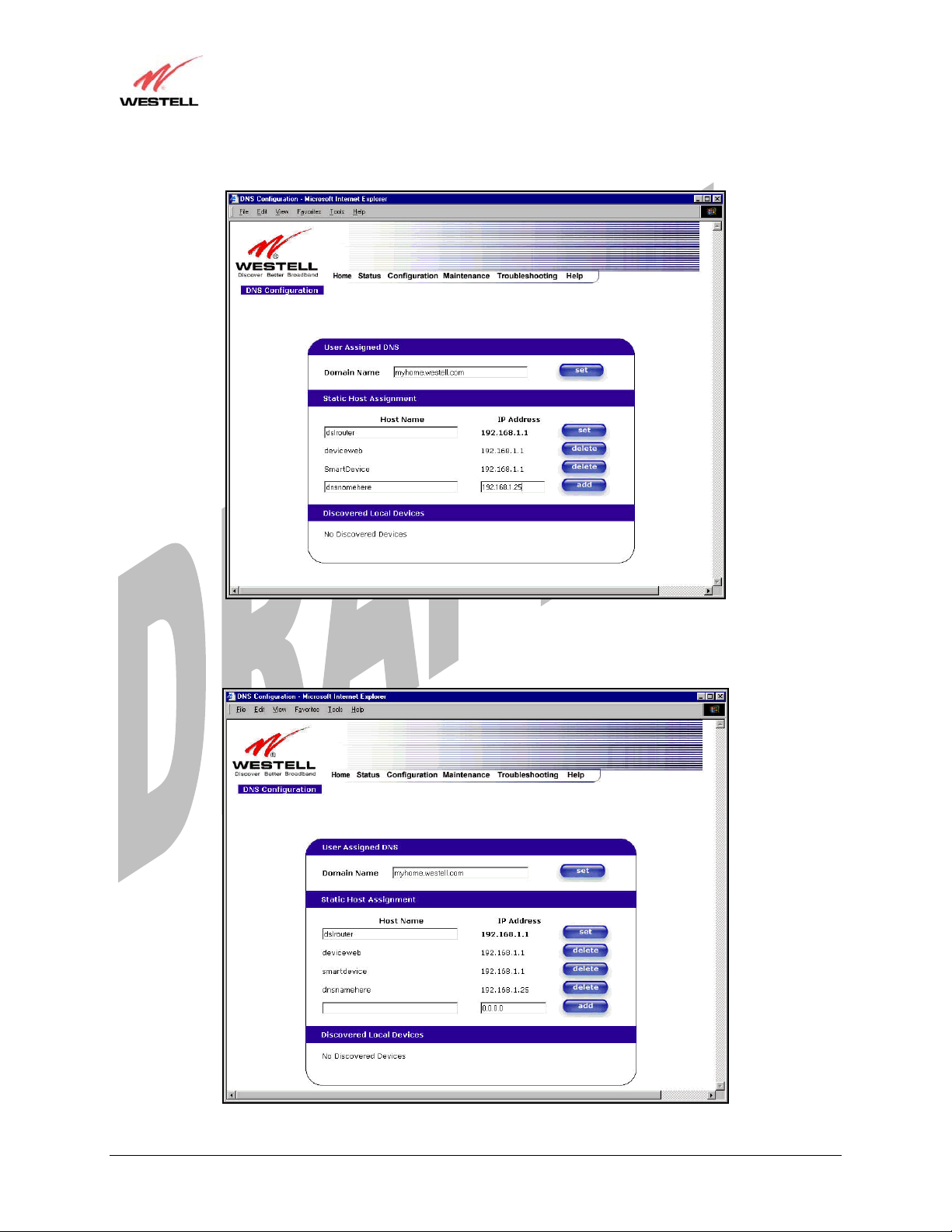
The following screen displays a Host Name and an IP Address in the fields. Now click on add.
Media Gateway (Model WMT)
If you clicked on add, the following screen will be displayed. The Host Name and IP Address have been added to
the Static Host Assignment.
030-300417 Rev. A 62 July 2006
Draft 1 - 07/11/06
User Guide
Media Gateway (Model WMT)
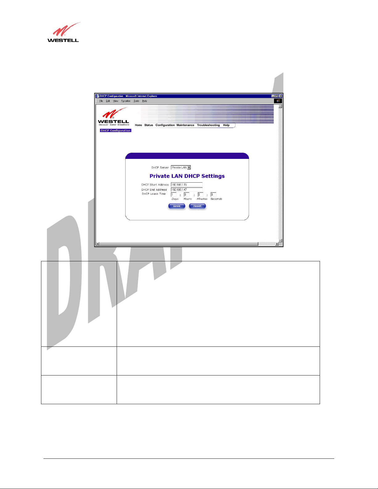
13.5.2 DHCP Configuration (Private LAN)
The following settings will be displayed if you select DHCP from the Advanced LAN menu.
DHCP Server This setting allows Media Gateway to automatically assign IP addresses to
local devices connected on the LAN. Westell advises setting this to enabled for
the private LAN.
Off = DHCP Server is disabled
Private LAN = DHCP addresses will be saved into the Private LAN
configuration.
Public LAN = DHCP addresses will be saved into the Public LAN
configuration. This option is only available if the Public LAN DHCP server is
enabled.
NOTE: These addresses will be overwritten if your ISP supports dynamic
setting of these values.
DHCP Start Address Factory Default = 192.168.1.15
This field displays the first IP address that the DHCP server will provide. The
DHCP Start Address must be within the IP address and lower than the DHCP
End Address. You may use any number from 0 to 254 in this address.
DHCP End Address Factory Default = 192.168.1.47
This field displays the last IP address that the DHCP server will provide. The
DHCP End Address must be within the IP address and higher than the DHCP
Start Address. You may use any number from 0 to 254 in this address.
030-300417 Rev. A 63 July 2006
Draft 1 - 07/11/06
User Guide
DHCP Lease Time Factory Default = 01:00:00:00
Displays the amount of time the provided addresses will be valid, after which
the DHCP client will usually re-submit a request.
NOTE: DHCP Lease Time is displayed in the format (dd:hh:mm:ss)*. This
value must be greater than 10 seconds. Seconds must be between 0 and 59,
minutes must be between 0 and 59, and hours must be between 0 and 23.
*(dd = days, hh = hours, mm = minutes, ss = seconds)
Media Gateway (Model WMT)
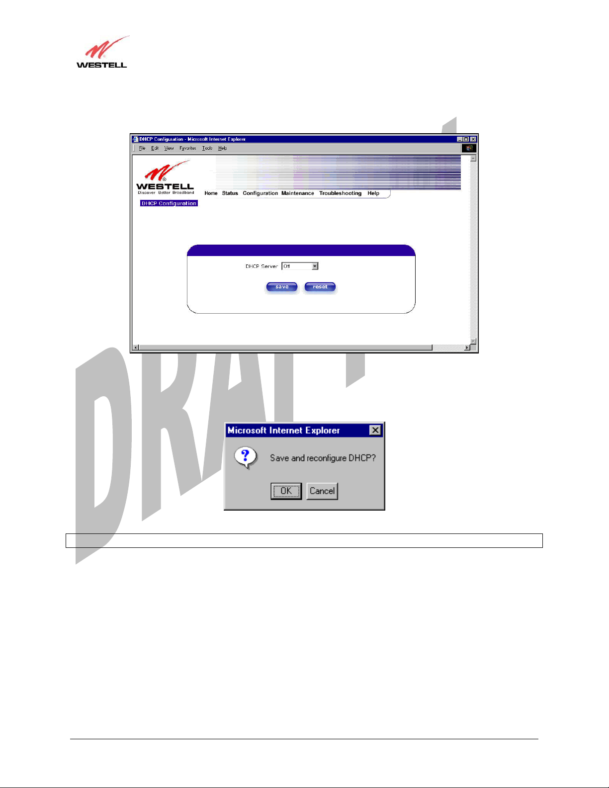
13.5.3 Disabling the DHCP Server
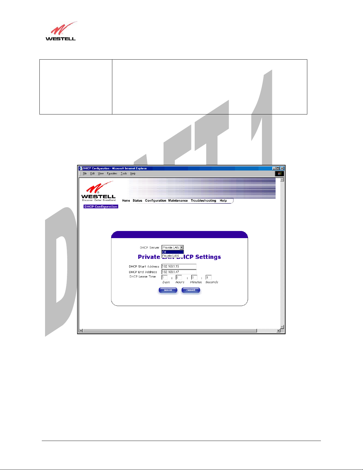
If you click on the drop-down arrow at DHCP Server:, a list of options will be displayed.
If you want to disable your DHCP server, select Off from the DHCP Server drop-down arrow. Click on save.
030-300417 Rev. A 64 July 2006
Draft 1 - 07/11/06
User Guide
If you selected Off at DHCP Server:, the following screen will be displayed. Click on save to save the DHCP
Server setting.
Media Gateway (Model WMT)
If you clicked on save, in the preceding DHCP Configuration screen, the following pop-up screen will appear.
Click on OK.
STOP: After you disable the DHCP server, you must reboot your PC
030-300417 Rev. A 65 July 2006
Draft 1 - 07/11/06
User Guide
Media Gateway (Model WMT)
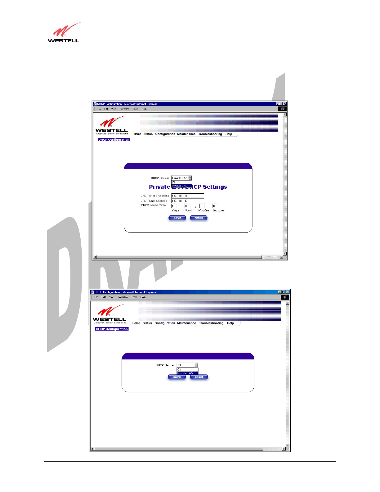
13.5.4 Enabling the DHCP Server
If you want to enable your DHCP Server settings, select Private LAN at the DHCP Server drop-down arrow.
If you have recently disabled the DHCP Server for Private LAN, select Private LAN while in the following screen.
030-300417 Rev. A 66 July 2006
Draft 1 - 07/11/06
User Guide
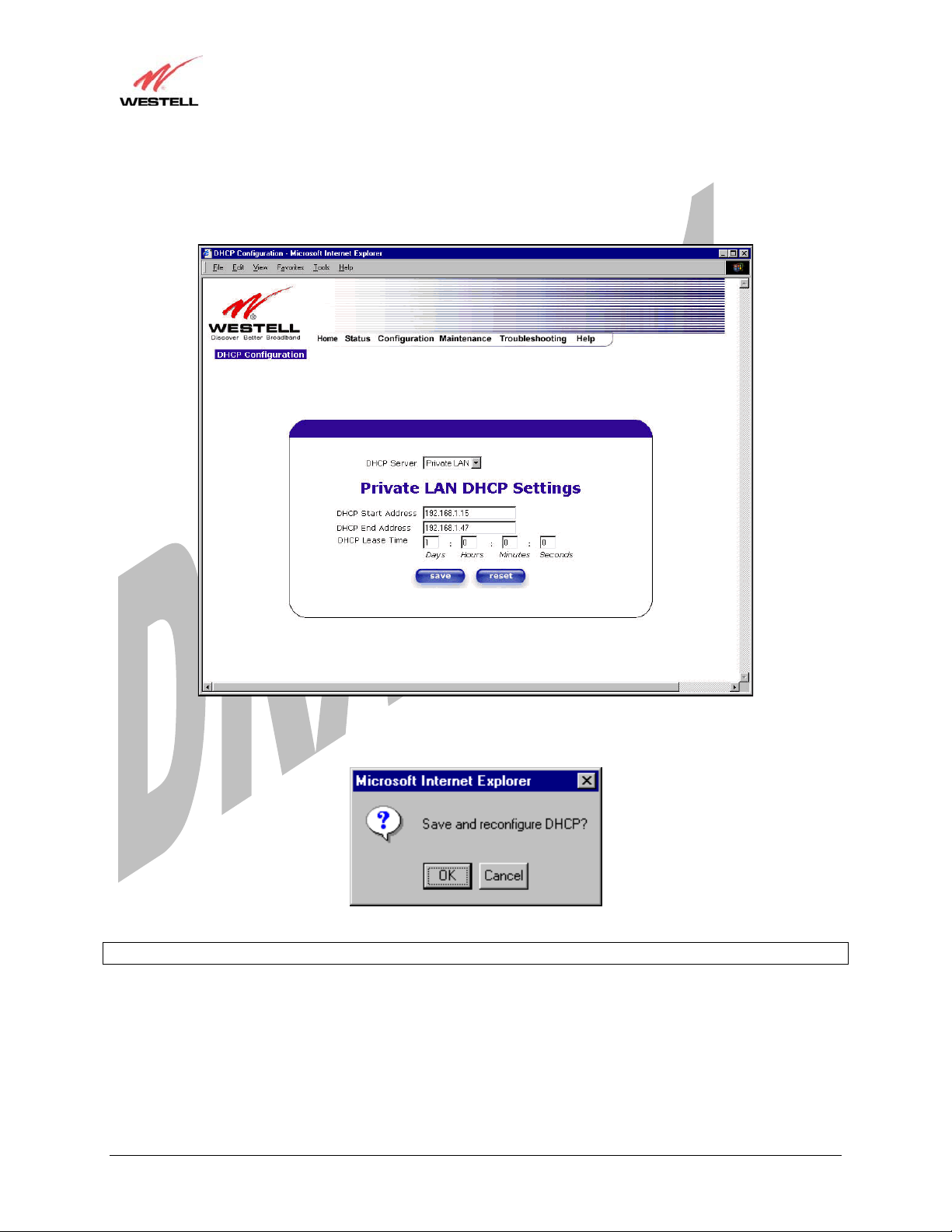
If you selected Private LAN, the following screen will be displayed automatically. Click on save to save your
DHCP Server setting. If you click on reset, your DHCP Server will be reset to factory default. (Private LAN is the
factory default for the DHCP Server.)
Media Gateway (Model WMT)
If you clicked on save, the following pop-up screen will appear. Click on OK.
STOP: After you enable the DHCP server, you must reboot your PC
030-300417 Rev. A 67 July 2006
Draft 1 - 07/11/06
User Guide
Media Gateway (Model WMT)
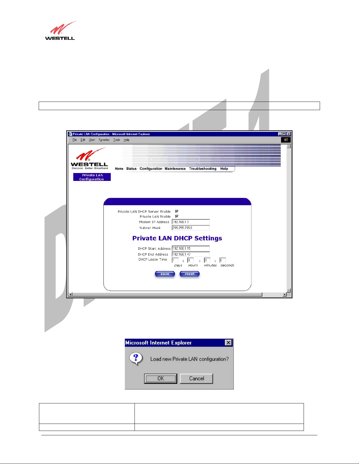
13.5.5 Private LAN Configuration – Configuring NAT
The following settings will be displayed if you select Private LAN from the Advanced LAN menu. (Private LAN
is the default configuration for the Media Gateway.)
NOTE: Private LAN allows you to set up a network behind the Media Gateway.
If you change the settings in this screen, click on save. If you click on reset, the changes will not take effect.
If you made changes and clicked on save, the following pop-up screen will be displayed. Click on OK. This will
save your Private LAN Configuration settings. If you click Cancel, your new settings will not take effect.
Private LAN DHCP Server Enable Default = CHECKED
If this box is CHECKED, it enables DHCP addresses to be served
from the Private LAN pool.
Private LAN Enable Default = CHECKED
030-300417 Rev. A 68 July 2006

Draft 1 - 07/11/06
User Guide
If this box is CHECKED, it enables the addresses from the Private
LAN to use the NAT interface.
Modem IP Address Displays the Media Gateway’s IP address
Subnet Mask Displays the Subnet Mask, which determines what portion of an IP
address is controlled by the network and which portion is controlled
by the host.
DHCP Start Address Displays the first IP address that the DHCP server will provide.
DHCP End Address Displays the last IP address that the DHCP server will provide.
DHCP Lease Time Displays the amount of time the provided addresses will be valid,
after which the DHCP client will usually re-submit a request.
NOTE: DHCP Lease Time is displayed in the following format: (dd:hh:mm:ss)* This value must be greater than 10
seconds. The default = 01:00:00:00. Seconds must be between 0 and 59, minutes must be between 0 and 59, and
hours must be between 0 and 23.
*(dd = days, hh = hours, mm = minutes, ss = seconds).
If the settings you have entered in the Private LAN Configuration screen are incorrect, the following warnings
messages may be displayed via pop-up screens. If this occurs, check the settings in the Private LAN Configuration
screen.
Warning Message Check Private LAN DHCP Settings
Start Address is not part of the Subnet Check the value in the DHCP Start Address field
End Address is not part of the Subnet Check the value in the DHCP End Address field
End Address is below the Start Address Check the value in the DHCP End Address field
Lease time must be greater than 10 seconds Check the values in the DHCP Lease Time fields
Seconds must be between 0 and 59 Check the Seconds value in the DHCP Lease Time field
Minutes must be between 0 and 59 Check the Minutes value in the DHCP Lease Time field
Hours must be between 0 and 23 Check the Hours value in the DHCP Lease Time field
Media Gateway (Model WMT)
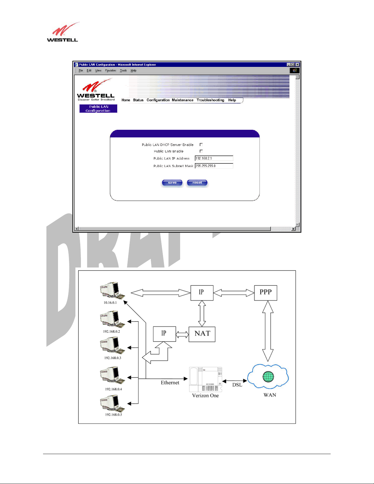
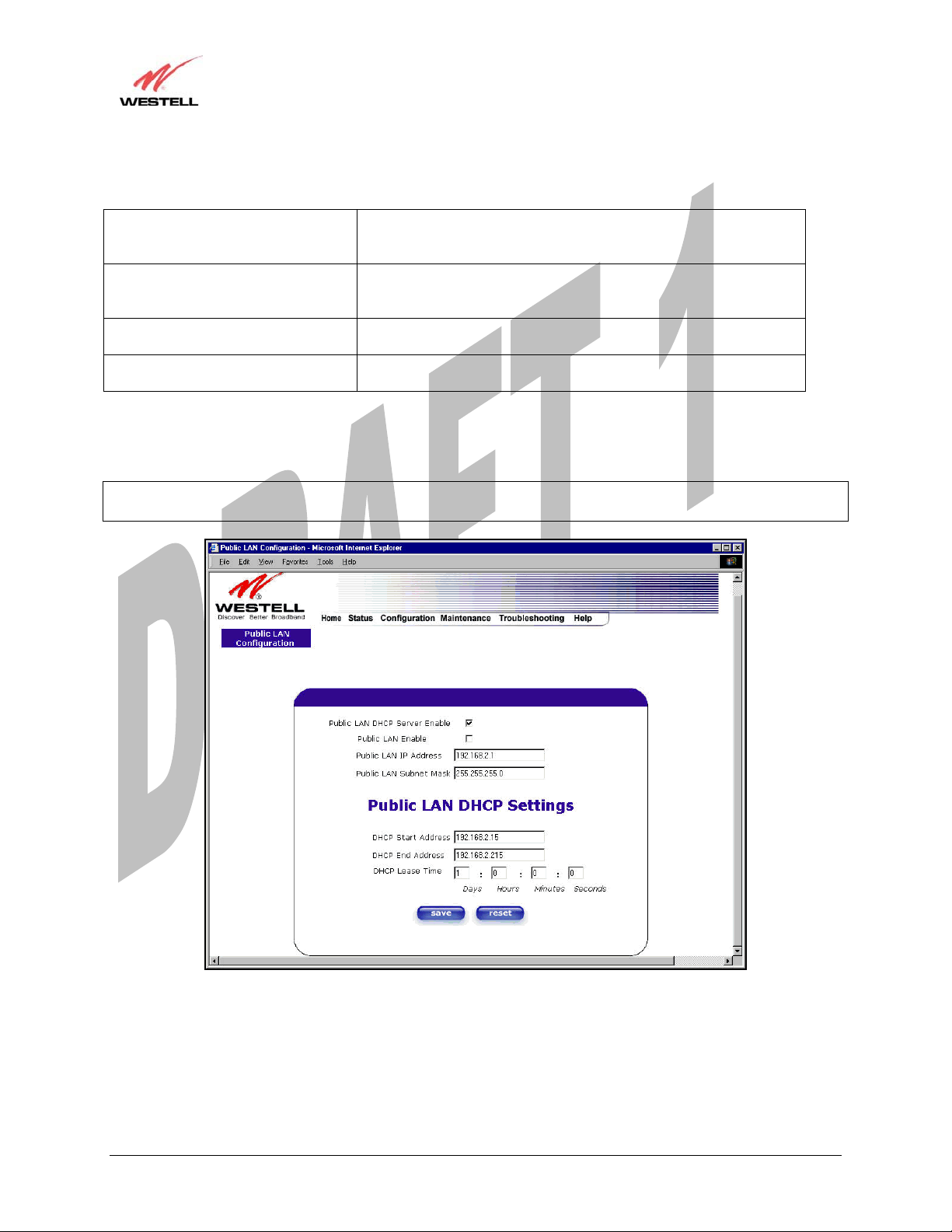
13.5.6 Public LAN Configuration – Multiple IP Address PassThrough
The following screen will be displayed if you select Public LAN from the Advanced LAN menu. Click in the
Public LAN DHCP Server Enable box. A check mark will appear in the box.
NOTE: The Public LAN feature, if available from your ISP, allows Media Gateway to use LAN IP addresses that
are accessible from the WAN. Public LAN allows your computer to have global address ability. To utilize the Public
LAN feature on the Media Gateway, your ISP must support Public LAN and Static IP. Contact your ISP for details.
030-300417 Rev. A 69 July 2006
Draft 1 - 07/11/06
User Guide
Media Gateway (Model WMT)
The public devices are visible on the Internet unlike a local NAT’ed PC. The example below shows four NAT’ed
PCs and one global PC. The arrows show the data path for each flow.
030-300417 Rev. A 70 July 2006
Draft 1 - 07/11/06
User Guide
Public LAN DHCP Server Enable Default = NOT CHECKED
If this box is CHECKED, it enables DHCP addresses to be served
from the Public LAN pool.
Public LAN Enable Default = NOT CHECKED
If this box is CHECKED, it enables the addresses from the Public
LAN to bypass the NAT interface.
Public LAN IP Address Provides a Public IP Address if your ISP does not automatically
provide one.
Public LAN Subnet Mask Provides a Public Subnet Mask if your ISP does not automatically
provide one.
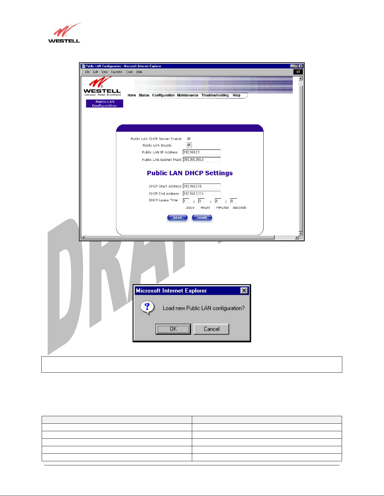
If you clicked on the Public LAN DHCP Server Enable box, the following screen will be displayed. Click on the
Public LAN Enable box to enable Public LAN.
NOTE: By enabling the Public LAN DHCP Server, you automatically disable the Private LAN DHCP Server on the
Media Gateway.
Media Gateway (Model WMT)
If you clicked on the Public LAN Enable box, the following screen will be displayed, showing the Public LAN
Enable box selected. Click on save.
030-300417 Rev. A 71 July 2006
Draft 1 - 07/11/06
User Guide
Media Gateway (Model WMT)
If you selected Public LAN Enable, or if you made other changes in the Public LAN Configuration screen and
clicked on save, the following pop-up screen will be displayed. Click on OK to save the new settings. If you click
on Cancel, your new settings will not take effect.
NOTE: DHCP Lease Time values must be greater than 10 seconds. The default = 01:00:00:00. Seconds must be
between 0 and 59, minutes must be between 0 and 59, and hours must be between 0 and 23.
If the settings you have entered in the Public LAN Configuration screen are incorrect, the following warnings
messages may be displayed via pop-up screens. If this occurs, check settings in the Public LAN Configuration
screen.
Warning Message Check Public LAN DHCP Settings
Start Address is not part of the Subnet Check the value in the DHCP Start Address field
End Address is not part of the Subnet Check the value in the DHCP End Address field
End Address is below the Start Address Check the value in the DHCP End Address field
Lease time must be greater than 10 seconds Check the values in the DHCP Lease Time fields
Seconds must be between 0 and 59 Check the Seconds field at DHCP Lease Time
030-300417 Rev. A 72 July 2006
Draft 1 - 07/11/06
User Guide
Minutes must be between 0 and 59 Check the Minutes field at DHCP Lease Time
Hours must be between 0 and 23 Check the Hours field at DHCP Lease Time
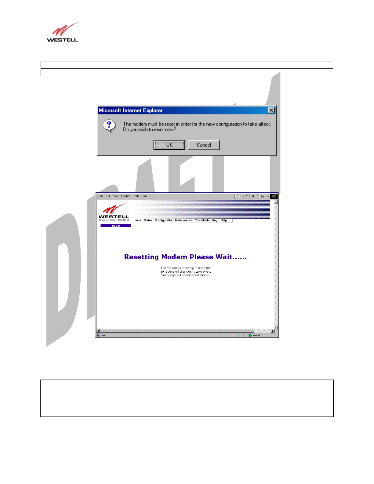
If you clicked on OK in the Load new Public LAN configuration? screen, the following pop-up screen will be
displayed. This will allow the modem to be reset and the new configuration will take effect. Click on OK.
If you clicked on OK in the preceding screen, the following screen will be displayed. Media Gateway will be reset
and the new configuration will take effect.
Media Gateway (Model WMT)
After a brief delay, the home page will be displayed. Confirm that your PPP session displays UP. (Click on the
connect button to establish a PPP session).
NOTE: Whenever the PPP Status displays DOWN, you do not have a PPP session established. If the Media
Gateway’s connection setting is set to “Always On,” after a brief delay the PPP session will be established
automatically and the PPP Status will display UP. If the connection setting is set to “Manual,” you must click on the
Connect button to establish a PPP session. Once the PPP session has been established (PPP Status displays UP),
you may proceed with the Media Gateway’s configuration.
030-300417 Rev. A 73 July 2006
Draft 1 - 07/11/06
User Guide
Media Gateway (Model WMT)
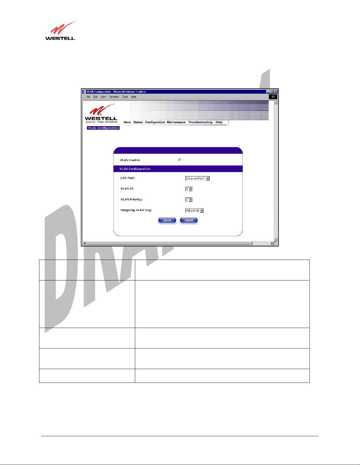
13.5.7 VLAN
The following settings will be displayed if you select VLAN from the Advanced LAN menu.
VLAN Enable Factory Default = DISABLED
If this box is check, VLAN will be Enabled. This will allow VLAN
tagging to occur according to the data port’s configuration.
LAN Port This allows you to select the LAN port that you wish to configure.
Possible responses are:
Ethernet Port 1
Ethernet Port 2
Ethernet Port 3
Ethernet Port 4
WLAN Port
VLAN ID This allows you to assign a VLAN ID to the port.
Possible responses are:
1 through 8
VLAN Priority This allows you to set the VLAN priority for the port.
Possible responses are:
0 through 7
Outgoing VLAN Tag This allows you to keep or remove the VLAN tag on the port when
data is outgoing.
030-300417 Rev. A 74 July 2006
Draft 1 - 07/11/06
User Guide
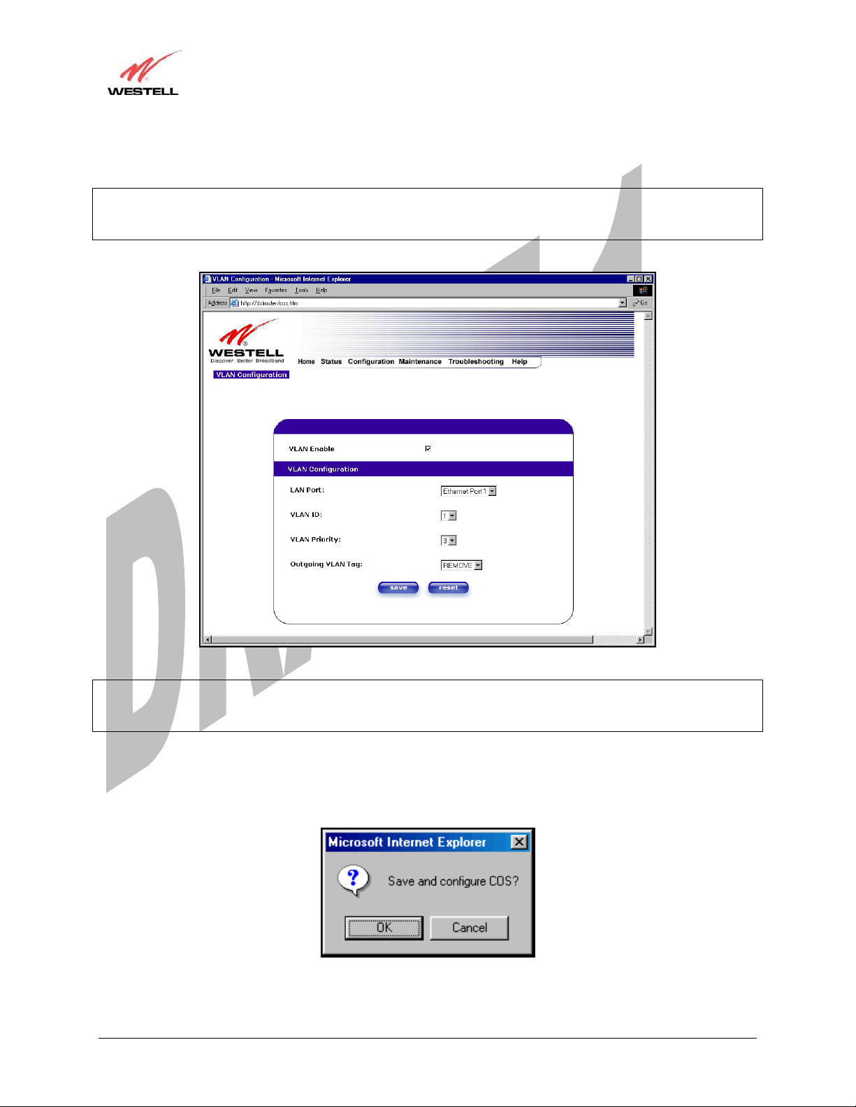
To enable VLAN click on the box adjacent to the VLAN Enable field. A check mark will appear in the box.
Click on save.
NOTE: For VLAN to function properly, the VLAN ID must be set to a value other than ‘1’ in VLAN
Configuration screen and in the VC 1 Configuration screen when the you are using the Bridge (VLAN Bridge)
protocol. See Advanced WAN section for configuring VC’s (refer to section 13.6.3).
Media Gateway (Model WMT)
NOTE: If you change the values in the VLAN Configuration screen and click the reset button, the screen will
display the previously set values for the LAN Port you have selected. If you change the settings in this screen, you
must click save to save the new settings.
If you click on save, the following pop-up screen will appear. Click OK in the pop-up screen to allow the new
settings to take effect.
030-300417 Rev. A 75 July 2006
Draft 1 - 07/11/06
User Guide
Media Gateway (Model WMT)
13.6 Advanced WAN
This section explains the configurable features of Media Gateway that are available if you select Advanced WAN
from the Configuration menu.
13.6.1 Editing the WAN Configuration
The following VC 1 Configuration screen will be displayed if you click on the edit button adjacent to any of the
‘Enabled’ protocols displayed in the WAN Configuration screen. (Note: The Protocol must be enabled before you
can edit its VC configuration.) The VC 1 Configuration screen allows you to edit your virtual connection (VC). A
virtual connection identifies a connection through the ATM network to your ISP. Unlike physical hardware
connections, virtual connections are defined by data.
If you change any of the VC settings in the following screen, click on the Set VC button.
NOTE: If you experience any problems, please reset Media Gateway via the external hardware reset button or via
the procedure defined under the Maintenance menu in section 15.1. The actual information displayed in this screen
may vary, depending on network connection established.
030-300417 Rev. A 76 July 2006

Draft 1 - 07/11/06
User Guide
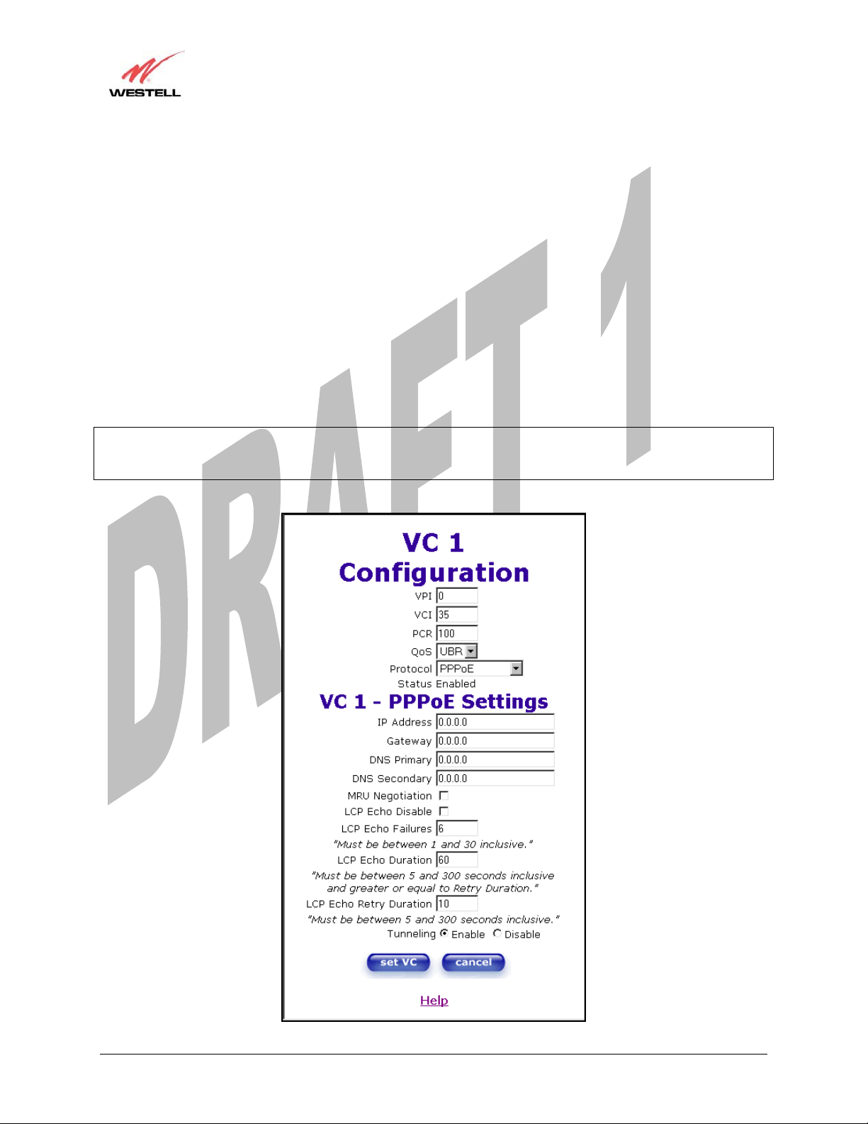
VC 1 Configuration
VPI This setting allows you to change your VPI (Virtual Path Indicator) value for a
particular VC, which is defined by your ISP.
VCI This setting allows you to change your VCI (Virtual Channel Indicator) value for a
particular VC, which is defined by your ISP.
PCR Factory Default = 100%
Peak Cell Rate (PCR)-The maximum rate at which cells can be transmitted across a
virtual circuit, specified in cells per second and defined by the interval between the
transmission of the last bit of one cell and the first bit of the next.
This value is a percentage of the current data rate.
100 allows this VC to use 100% of the available bandwidth.
80 allows this VC to use 80% of the available bandwidth.
QoS Quality of Service, which is determined by your ISP.
Possible Responses:
CBR = Constant Bit Rate
UBR = Unspecified Bit Rate
VBR = Variable Bit Rate
Protocol The Protocol for each VC, which is specified by your ISP.
Possible Responses:
PPPoA = Point to Point Protocol over ATM (Asynchronous Transfer Mode)
PPPoE = Point to Point Protocol over Ethernet
Bridge = Bridge Protocol
Classical IPoA = Internet Protocol over ATM (Asynchronous Transfer Mode). This
is an ATM encapsulation of the IP protocol.
Status The protocol status.
VC x PPPoE Settings
IP Address Displays the IP network address that your modem is on.
Gateway Displays the Media Gateway’s IP address
DNS Primary Provided by your ISP.
DNS Secondary Provided by your ISP.
MRU Negotiation Factory Default = DISABLED
If ENABLED, the Maximum Received Unit (MRU) would enforce MRU
negotiations. (NOTE: enable this option only if your ISP instructs you to do so.)
LCP Echo Disable Factory Default = Enable
If checked, this option will disable the modem LCP Echo transmissions.
LCP Echo Failures Indicates number of continuous LCP echo non-responses received before the PPP
session is terminated.
LCP Echo Retry Duration The interval between LCP Echo transmissions with responses.
LCP Echo Retry Duration The interval between LCP. Echo after no response.
Tunneling Factory Default = ENABLE
If ENABLED, this option allows PPP traffic to be bridged to the WAN. This feature
allows you to use a PPPoE shim on the host computer to connect to your ISP, by
bypassing the Media Gateway’s capability to do this.
NOTE: Tunneling is available in PPPoE mode only.
Media Gateway (Model WMT)
NOTE: The values for IP Address, Gateway, DNS Primary, and DNS Secondary are all “Override of the value
obtained from the PPP connection,” They default to “0.0.0.0,” in which case the override is ignored. Westell
recommends that you do not change the values unless your ISP instructs you to change them.
030-300417 Rev. A 77 July 2006
Draft 1 - 07/11/06
User Guide
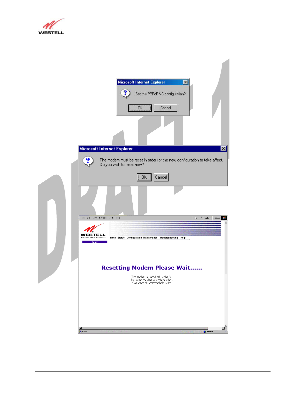
If you have made any changes to your VC settings, you need to save them. To save the new VC settings, click on
OK when asked Set this PPPoE VC configuration? If you click on cancel, the new VC settings will not be saved.
If you clicked on OK in the preceding pop-up screen, the following pop-up screen will appear. Media Gateway must
be reset to allow the new configuration to take effect. Click on OK.
Media Gateway (Model WMT)
If you clicked on OK in the preceding screen, the following screen will be displayed. Media Gateway will be reset
and the new configuration will take effect.
After a brief delay, the home page will be displayed. Confirm that your PPP session displays UP. (Click on the
connect button to establish a PPP session).
030-300417 Rev. A 78 July 2006
Draft 1 - 07/11/06
User Guide
Media Gateway (Model WMT)
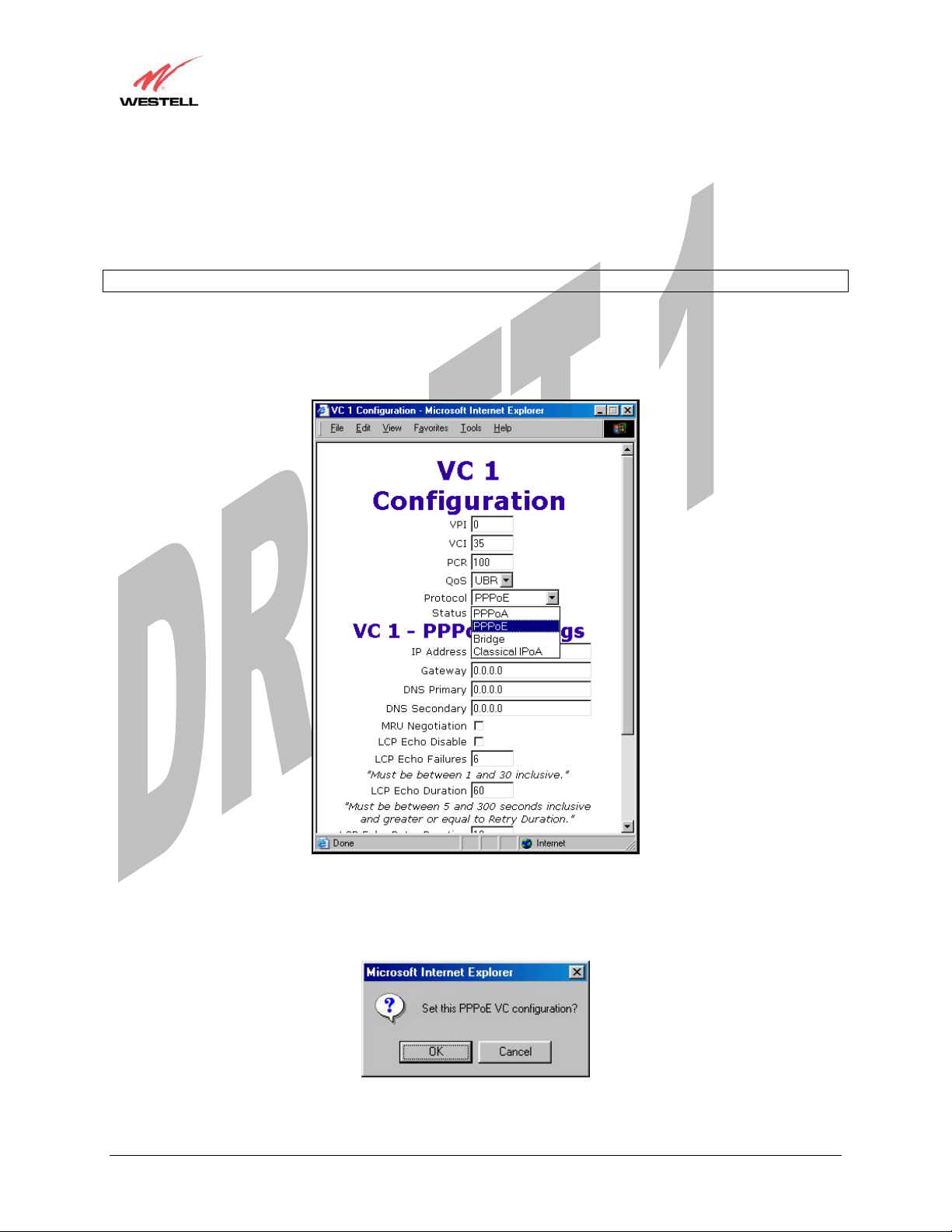
13.6.2 Configuring the Media Gateway’s Protocol Settings for PPPoE Mode
To configure the Media Gateway’s protocol settings for PPPoE mode, select WAN from the Advanced WAN menu.
The WAN Configuration screen will be displayed. Next, click on the edit button adjacent to any of the existing
‘Enabled’ VC (Virtual Connection) protocols.
NOTE: The protocol status must display “Enable” to allow edits to its VC configuration.
If you clicked on edit in the WAN Configuration screen, the following VC 1 Configuration screen will be
displayed. Select PPPoE from the options listed in Protocol drop-down arrow. After you have made the
configuration for this protocol, select the set VC button.
If you click the set VC button, the following pop-up screen will be displayed. Click on OK in the pop-up screen. If
you click on Cancel, the new settings will not be saved. After you click on OK, follow the instructions to reset your
Gateway, as previously discussed in section 13.6.1.
030-300417 Rev. A 79 July 2006
Draft 1 - 07/11/06
User Guide
Media Gateway (Model WMT)
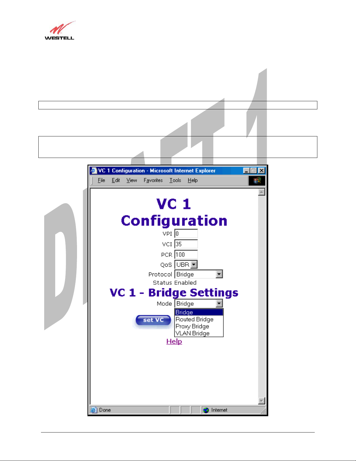
13.6.3Configuring the Media Gateway’s Protocol Settings for Bridge Mode
To configure the Media Gateway’s protocol settings for Bridge mode, select WAN from the Advanced WAN menu.
The WAN Configuration screen will be displayed. Next, click on the edit button adjacent to any of the existing
‘Enabled’ VC (Virtual Connection) protocols. The VC1 Configuration screen will be displayed.
NOTE: The protocol status must display “Enable” to allow edits to its VC configuration.
If you select Bridge protocol from the Protocol drop-down arrow, the following screen will be displayed. Select a
mode from the options listed in the Mode drop-down arrow, under VC 1 – Bridge Settings.
NOTE: In certain network configurations, the user must configure the Media Gateway’s VC protocol settings for
“Routed Bridge” and “DHCP enable.” Please refer to your Internet service provider for instructions on protocol
settings.
030-300417 Rev. A 80 July 2006

Draft 1 - 07/11/06
User Guide
VC 1 Configuration
VPI This setting allows you to change your VPI (Virtual Path Indicator) value for a
particular VC, which is defined by your ISP.
VCI This setting allows you to change your VCI (Virtual Channel Indicator) value for a
particular VC, which is defined by your ISP.
PCR Factory Default = 100%
Peak Cell Rate (PCR)-The maximum rate at which cells can be transmitted across a
virtual circuit, specified in cells per second and defined by the interval between the
transmission of the last bit of one cell and the first bit of the next.
This value is a percentage of the current data rate.
100 allows this VC to use 100% of the available bandwidth.
80 allows this VC to use 80% of the available bandwidth.
QoS Quality of Service, which is determined by your ISP.
CBR = Constant Bit Rate
UBR = Unspecified Bit Rate
VBR = Variable Bit Rate
Protocol The Protocol for each VC, which is specified by your ISP.
Media Gateway (Model WMT)
PPPoA = Point to Point Protocol over ATM (Asynchronous Transfer Mode)
PPPoE = Point to Point Protocol over Ethernet
Bridge = Bridge Protocol
Classical IPoA = Internet Protocol over ATM (Asynchronous Transfer Mode). This
is an ATM encapsulation of the IP protocol.
Status The protocol status.
VC 1 Bridge Settings
Bridge = A bridge is a layer 2 device that connects two segments of the same LAN that use the
same protocol such as Ethernet. The modem does not have a WAN IP address in this mode. The
client PC will typically get an IP address from a DHCP server in the network or the IP address can
be assigned to the client PC statically.
Routed Bridge = Routed Bridged Encapsulation (RBE) is the process by which a bridged segment
is terminated on a routed interface. Specifically, your ISP is routing on an IEEE 802.3 or Ethernet
header carried over RFC 1483 bridged ATM. RBE was developed to address the known
RFC1483 bridging issues, including broadcast storms and security. The modem will get a WAN
Mode
IP address through DHCP or can be assigned statically. NAT will use the global address assigned
to the modem.
Proxy Bridge = Proxy Bridge is the process in which the modem acts as a proxy ARP agent for a
local public subnet. The modem will be assigned an IP address from within that public subnet.
The modem will direct all traffic to your ISP’s Gateway, which is configured statically. Media
Gateway address must not reside within your ISP’s Gateway assigned public subnet. All traffic
will be sent via the Media Gateway’s MAC address. The LAN may also have a private NAT'ed
network. NAT will use the global address assigned to the modem.
VLAN = Assigns VLAN tags to individual data ports on the modem.
030-300417 Rev. A 81 July 2006
Draft 1 - 07/11/06
User Guide
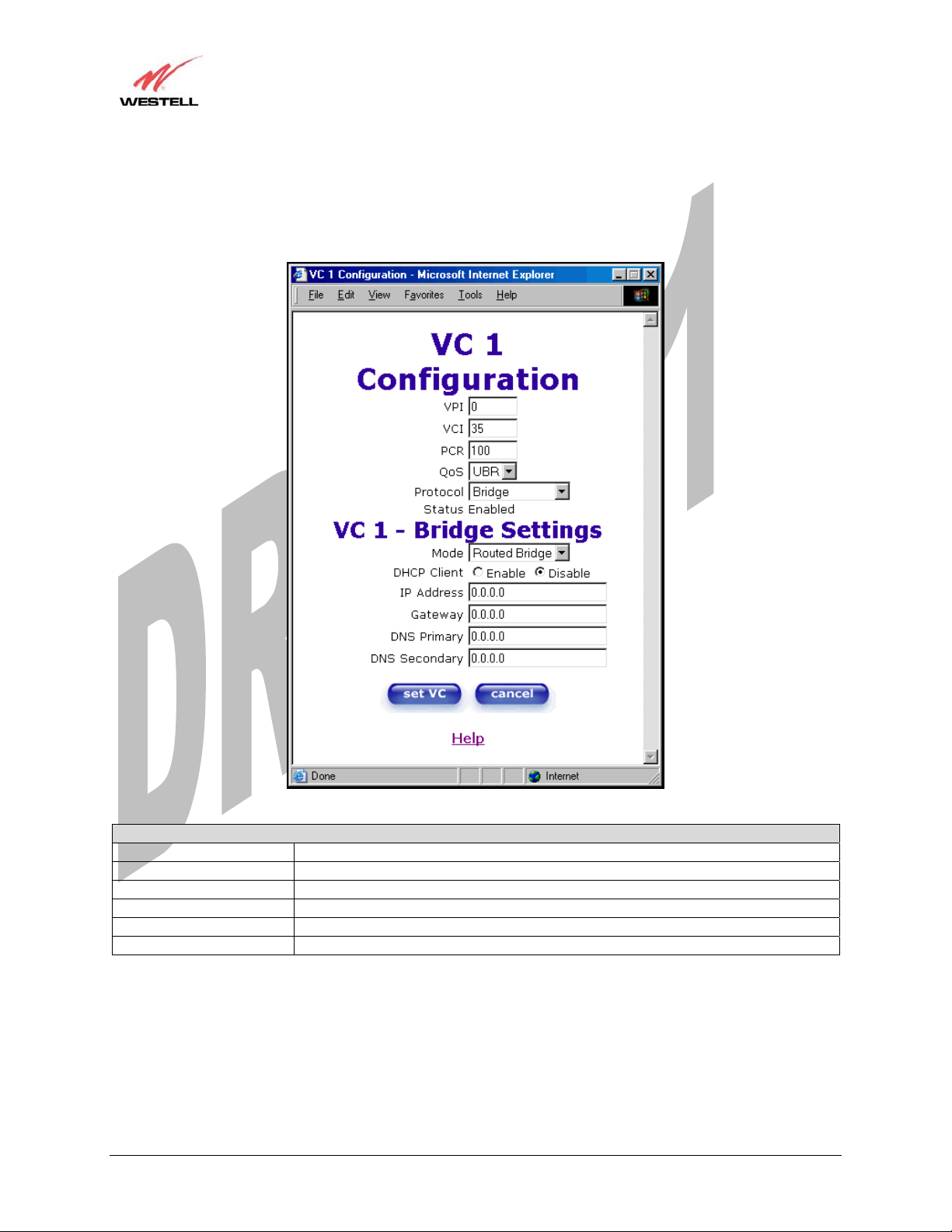
If you selected the Routed Bridge mode under VC 1- Bridge Settings, the following screen will be displayed.
Enter the appropriate values in the fields and click on set VC.
Media Gateway (Model WMT)
VC 1 - Bridge Settings (Routed Bridge)
Mode The Mode you have selected to use with Bridge protocol.
DHCP Client Selecting a radio button allows you to either Enable or Disable the DHCP Client.
IP Address Displays the IP network address that your modem is on.
Gateway Displays the modem’s IP gateway address.
DNS Primary Provided by your ISP.
DNS Secondary Provided by your ISP.
030-300417 Rev. A 82 July 2006
 Loading...