

Westell A90427XXX-07 Users Manual
User Guide
TriLink Gateway – Draft 5
030-300445 Rev. A
6/22/05
TriLink Gateway (Models 427V10, 427V11)
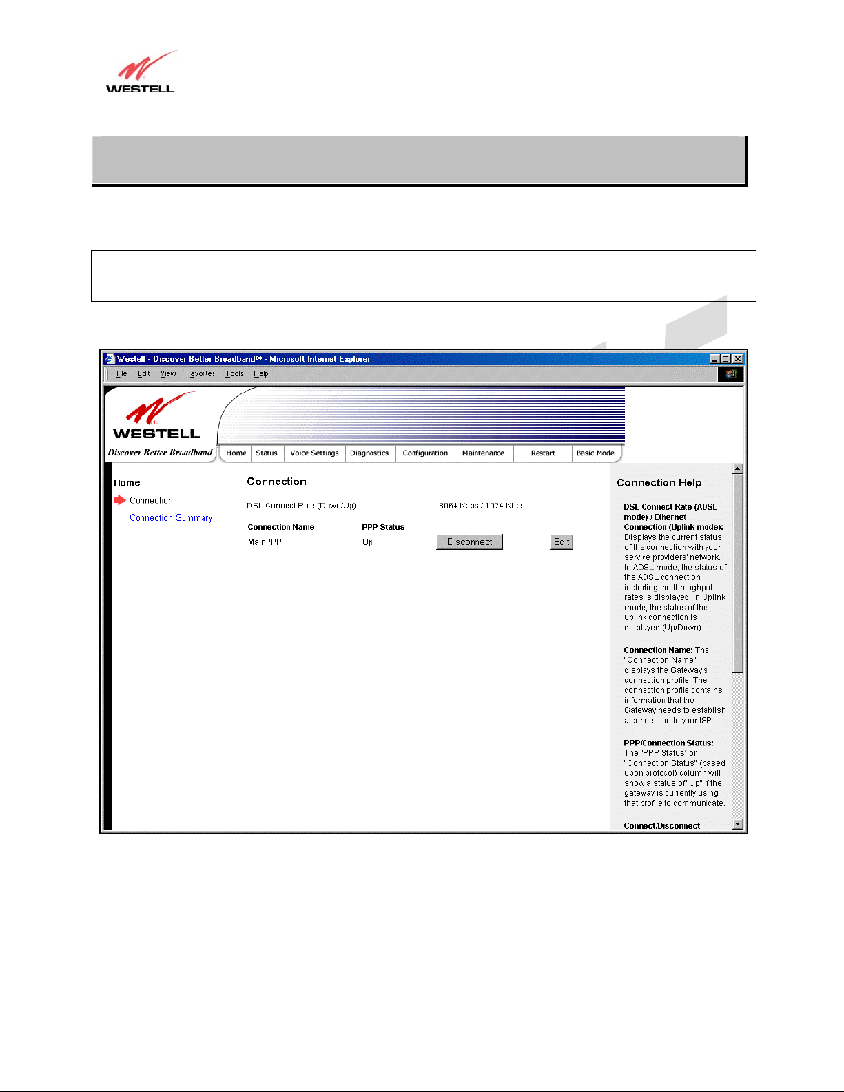
16. ADVANCED MODE
To set up the advanced configurations of your Router, select Advanced Mode (if you are in Basic Mode) from the
main menu. The following screen will be displayed.
NOTE: The basic operations of your Router were discussed earlier in this User Guide and provided details on the
Home, Status, Voice Settings, Diagnostics, and Restart features. For instructions on configuring any of these
features, refer to the Basic Mode sections (beginning with section 10) of this User Guide.
The advanced features of your Router will be discussed in sections 17, 18, and 19.
030-300445 Rev. A 61 June 2005
User Guide
TriLink Gateway – Draft 5
030-300445 Rev. A
6/22/05
TriLink Gateway (Models 427V10, 427V11)
17. CONFIGURATION
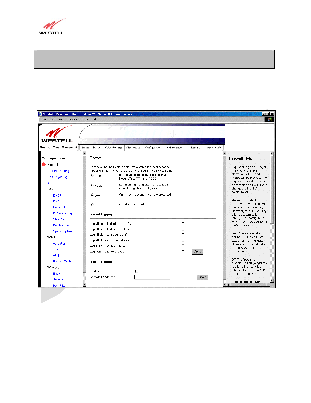
17.1 Firewall Configuration
The following screen will be displayed if you select Firewall from the Configuration menu. If you change any
settings in this screen, you must click save to save the settings.
Security Level
High High security level only allows basic Internet functionality. Only Mail,
News, Web, FTP, and IPSEC are allowed . All other traffic is prohibited.
Medium Like High security, Medium security only allows basic Internet
functionality by default. However, Medium security allows
customization through NAT configuration so that you can enable the
traffic that you want to pass.
Low Factory Default = Low
The Low security setting will allow all traffic except for known attacks.
If security is set to Low, the Router will be visible to other computers on
the Internet.
Off Firewall is disabled. (All traffic is passed)
030-300445 Rev. A 62 June 2005
TriLink Gateway – Draft 5
030-300445 Rev. A
6/22/05
TriLink Gateway (Models 427V10, 427V11)
User Guide
Firewall Logging
Log all permitted inbound traffic Factory Default = Disabled
If Enabled (box is checked), this function will be activated.
Log all permitted outbound traffic Factory Default = Disabled
If Enabled (box is checked), this function will be activated.
Log all blocked inbound traffic Factory Default = Disabled
If Enabled (box is checked), this function will be activated.
Log all blocked outbound traffic Factory Default = Disabled
If Enabled (box is unchecked), this function will be activated.
Log traffic specified in rules Factory Default = Disabled
If Enabled (box is checked), this function will be activated.
Log administrative access Factory Default = Disabled
If Enabled (box is checked), this function will be activated.
Remote Logging
Enable Factory Default = Disable
If Enabled (box is checked), the Router will send firewall logs to a syslog
server.
Remote IP Address The IP address of the syslog server machine to which the diagnostics logs
to be sent.
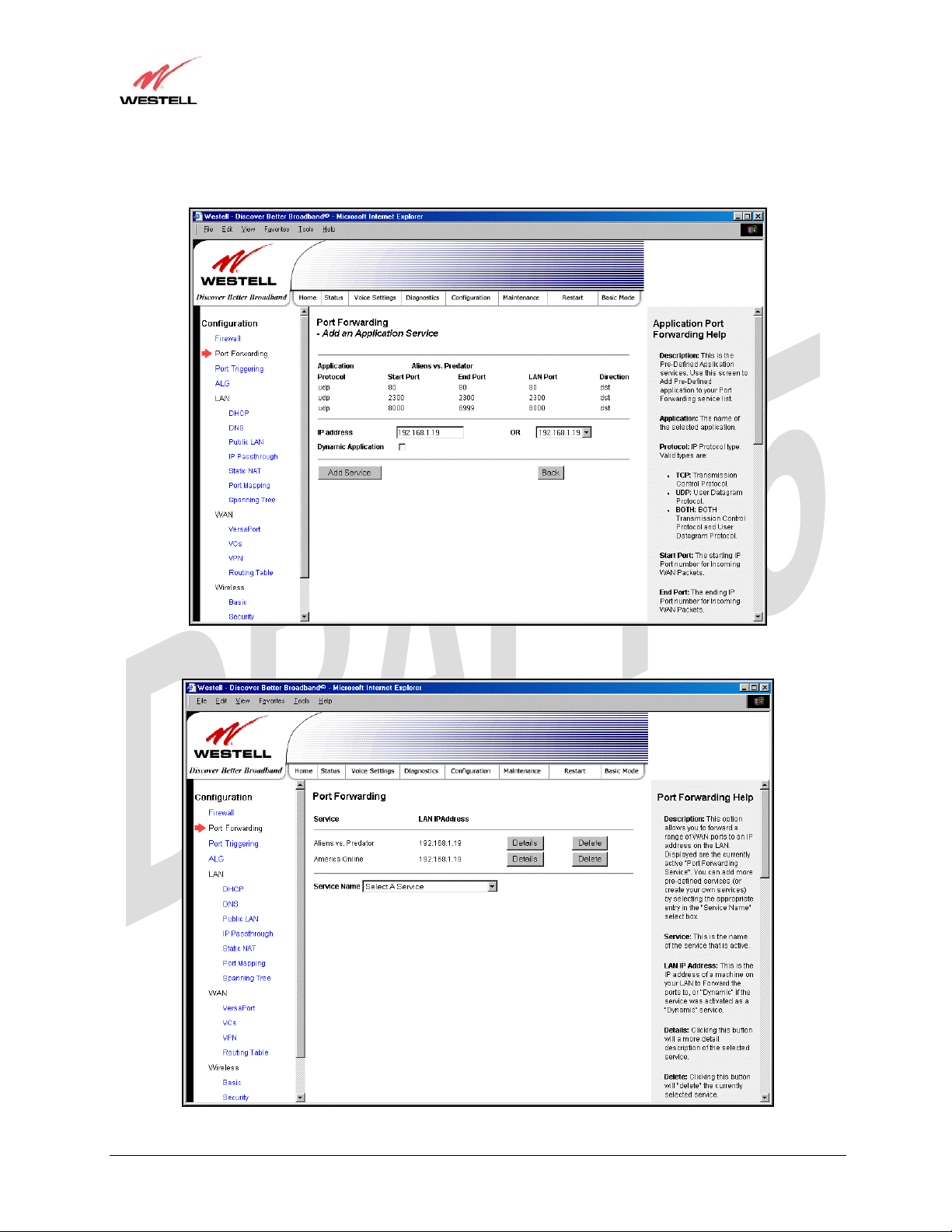
17.2 Port Forwarding Configuration
The following screen will be displayed if you select Port Forwarding from the Configuration menu. Port
Forwarding enables you to set up the Router’s port forwarding attributes for the services you add to your profile.
030-300445 Rev. A 63 June 2005
TriLink Gateway – Draft 5
030-300445 Rev. A
6/22/05
TriLink Gateway (Models 427V10, 427V11)
User Guide
To set up port forwarding, select a service from the Service Name drop- d own menu.
Note: You may add an unlimited numbers of services to your profile.
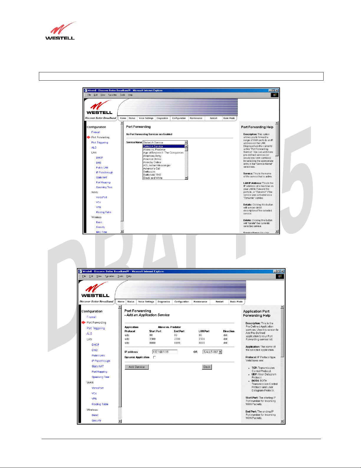
After you have selected a service name from the Service Name drop-down menu, the following Port Forwarding –
Add an Application Service screen will be displayed. Enter the appropriate IP address or machine name in the fields
provided and then click Add Service. Repeat these steps to add additional services to your profile.
030-300445 Rev. A 64 June 2005

TriLink Gateway – Draft 5
030-300445 Rev. A
6/22/05
TriLink Gateway (Models 427V10, 427V11)
User Guide
Application Protocol The IP Protocol type that is assigned to this service.
Start Port The start port that is assigned to the service
End Port The end port that is assigned to the service
LAN Port The LAN port that is assigned to the service.
Direction The traffic direction assigned to the service.
IP Address The LAN IP address or the machine name assigned to your service
Dynamic Application Factory Default = Disabled
If Enabled (box is checked), this will only allow outgoing connections
from any local PC.
If Disabled, packets will be forwarded to the designated local PC.
If you clicked Add Service, the following screen will be displayed. To view the details of a service you have added,
click the Details button adjacent to the service you want to view.
030-300445 Rev. A 65 June 2005
TriLink Gateway – Draft 5
030-300445 Rev. A
6/22/05
TriLink Gateway (Models 427V10, 427V11)
User Guide
If you clicked the Details button, the following screen will be displayed. After viewing the details of your service,
click Back to return to the preceding Port Forwarding screen.
To delete a service that you have added, click the Delete button adjacent to the service you want to remove.
030-300445 Rev. A 66 June 2005
TriLink Gateway – Draft 5
030-300445 Rev. A
6/22/05
TriLink Gateway (Models 427V10, 427V11)
User Guide
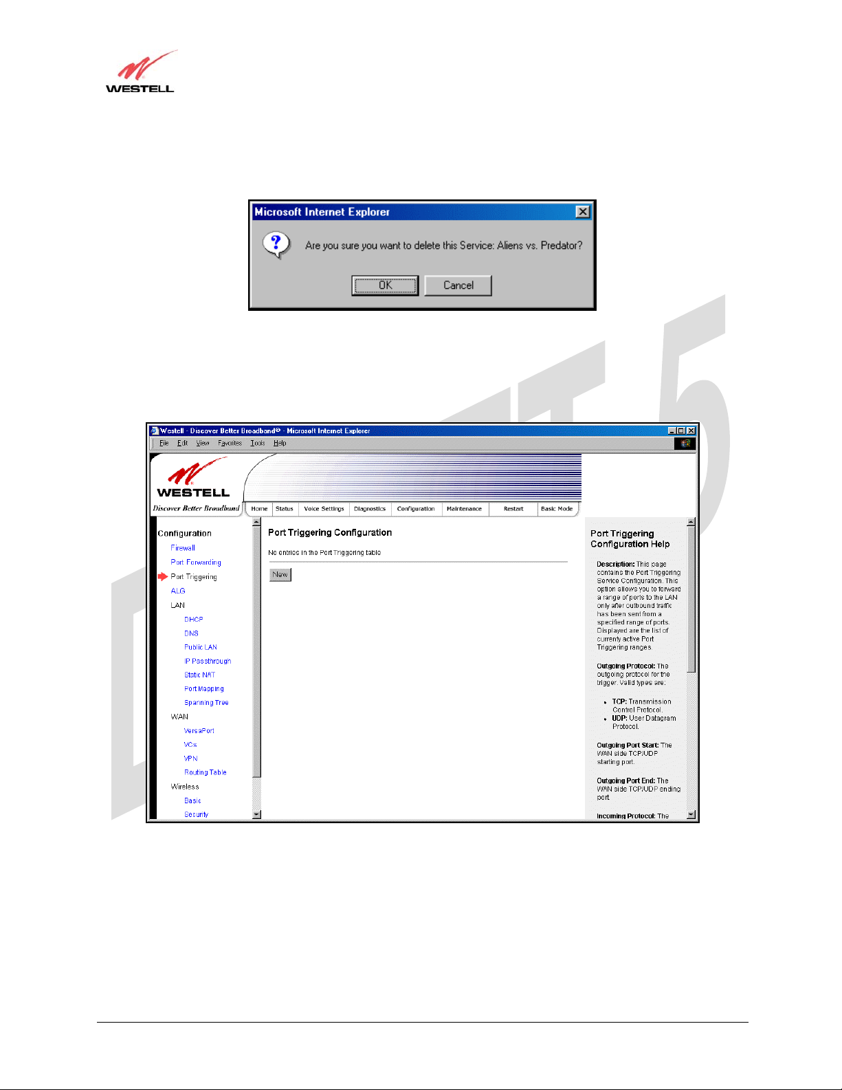
If you clicked Delete in the preceding screen, the following pop-up screen will be displayed. Click OK in the pop-
up screen; the service will then be removed from the list of selected services. Click Cancel if you do not want to
delete the selected service.
17.3 Port Triggering
The following screen will be displayed if you select Port Triggering from the Configuration menu. To create a trigger
port, click New.
030-300445 Rev. A 67 June 2005

TriLink Gateway – Draft 5
030-300445 Rev. A
6/22/05
TriLink Gateway (Models 427V10, 427V11)
User Guide
If you clicked New, the following screen will be displayed. Enter the appropriate values and click Save to save your
settings.
Port Triggering Configuration
Outgoing Protocol Factory Default = TCP
The outgoing protocol for the triggered po rt s.
Possible Response:
TCP – Transmission Control Protocol
UDP – User Datagram Protocol
Outgoing Port Start The WAN-side TCP/UDP starting port
Outgoing Port End The WAN-side TCP/UDP ending port
Incoming Protocol Factory Default = TCP
The incoming protocol for the triggered ports.
Possible Response:
TCP- Transmission Control Protocol
UDP- User Datagram Protocol
Both – TCP and UDP
Incoming Port Start The local LAN-side starting port.
Incoming Port End The local LAN-side ending port.
030-300445 Rev. A 68 June 2005
TriLink Gateway – Draft 5
030-300445 Rev. A
6/22/05
TriLink Gateway (Models 427V10, 427V11)
User Guide
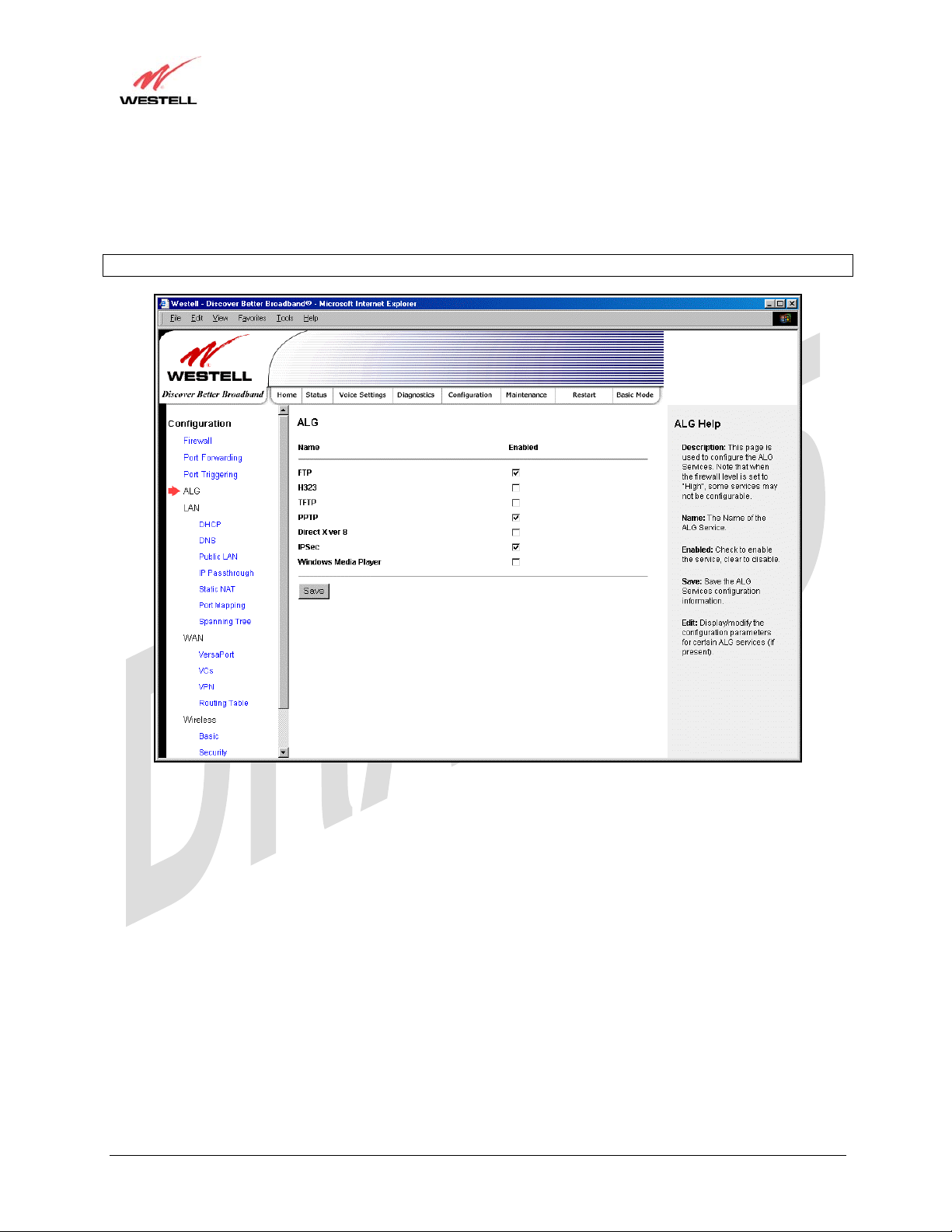
17.4 ALG Configuration
The following screen will be displayed if you select ALG from the Configuration menu. This page enables you to
configure ALG services for your Router. Enter the appropriate settings and then click Save to save the settings.
Note: When the firewall level is set to “High,” some services may not be configurable.
030-300445 Rev. A 69 June 2005
play
User Guide
TriLink Gateway – Draft 5
030-300445 Rev. A
6/22/05
TriLink Gateway (Models 427V10, 427V11)
17.5 LAN Configuration
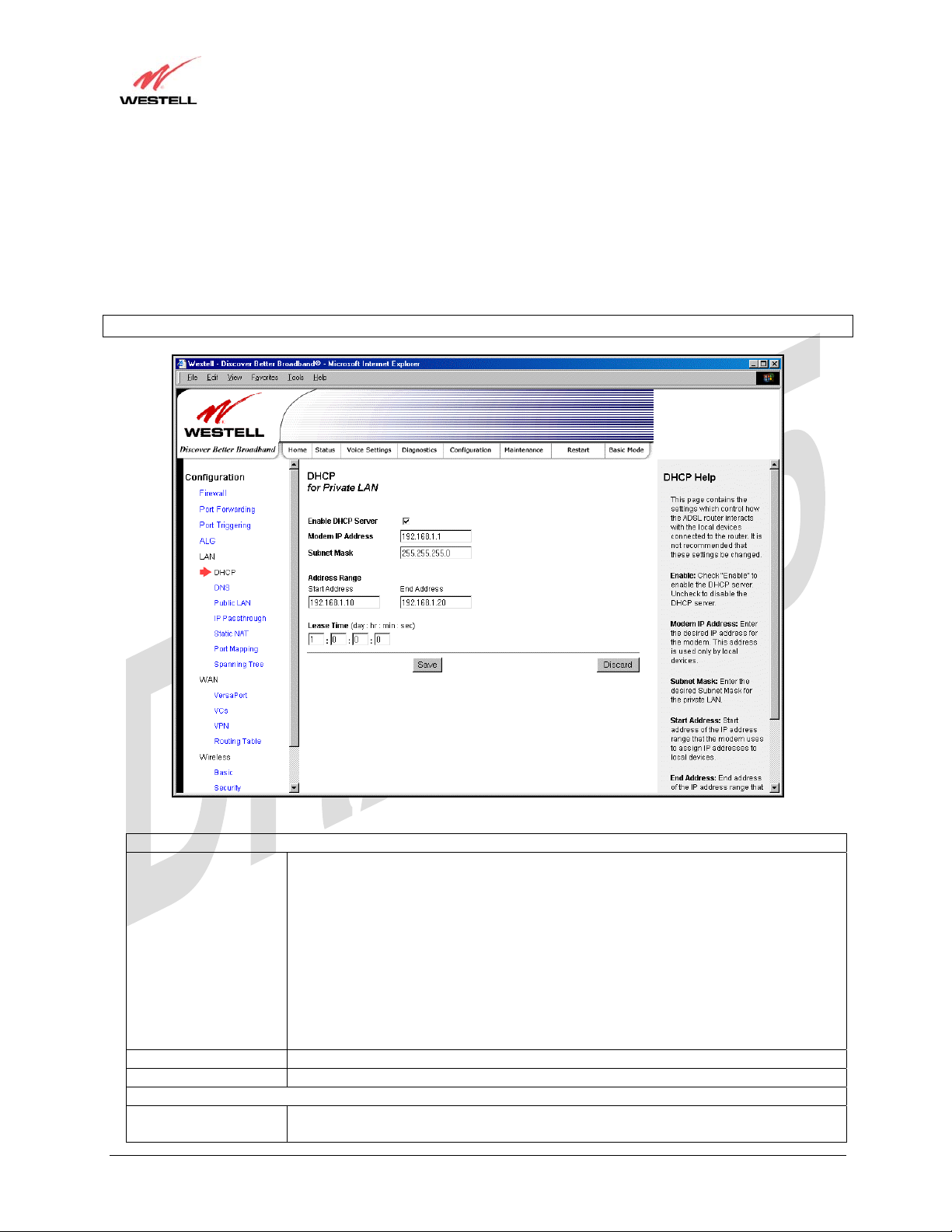
17.5.1 DHCP
The following screen will be displayed if you select LAN > DHCP from the Configuration menu. This page enables
you to control how the Router interacts with local devices to which it is connected. Enter the appropriate values, and
then click Save to save your settings.
Note: Westell recommends that you do not change these settings unless instructed by your Internet service provider.
DHCP Configuration for Private LAN
Enable DHCP Server Factory Default = Enable
This setting allows the Router to automatically assign IP addresses to local devices
connected on the LAN. Westell advises setting this to enabled for the private LAN.
Private LAN = DHCP addresses will be saved into the Private LAN configuration.
Public LAN = DHCP addresses will be saved into the Public LAN configuration. (This
option is only available if the Public LAN DHCP server is enabled.)
Possible Response:
If this box is checked, the DHCP server will be turned On.
If this box is unchecked, the DHCP server will be turned Off.
NOTE: These addresses will be overwritten if the Internet Service Provider supports
dynamic setting of these values.
Modem IP Address The IP Address of the Router
Subnet Mask The Subnet Mask of the Router
Address Range
DHCP Start Address Factory Default = 192.168.1.10
This field dis
s the first IP address that the DHCP server will provide. The DHCP
030-300445 Rev. A 70 June 2005

TriLink Gateway – Draft 5
030-300445 Rev. A
6/22/05
TriLink Gateway (Models 427V10, 427V11)
User Guide
Start Address must be within the IP address and lower than the DHCP End Address.
You may use any number from 0 to 254 in this address.
DHCP End Address Factory Default = 192.168.1.20
This field displays the last IP address that the DHCP server will provide. The DHCP
End Address must be within the IP address and higher than the DHCP Start Address.
You may use any number from 0 to 254 in this address.
DHCP Lease Time Factory Default = 01:00:00:00
Displays the amount of time the provided addresses will be valid, after which the
DHCP client will usually re-submit a request.
NOTE: DHCP Lease Time is displayed in the format (day:hour:min:sec)*. This value
must be greater than 10 seconds. Seconds must be between 0 and 59, minutes must be
between 0 and 59, and hours must be between 0 and 23.
17.5.2 DNS
The following screen will be displayed if you select LAN > DNS from the Configuration menu.
DNS
Domain Name
NOTE: Some ISP’s may require the
name for identification purposes.
This field allows you to enter a Domain Name for the Router.
To add a Domain Name, in the field under User Assigned DNS, type in
your new domain name and click Set.
Static Host Assignment
Host Name This field allows you to enter a HOST name for the Router.
To add a new Host name, in the field under Static Host Assi gnment, type
in the Host Name and the associated IP address and then click Add.
To delete a Host name, click the Delete button adjacent to the Host Name
and IP Address you want to delete.
030-300445 Rev. A 71 June 2005
TriLink Gateway – Draft 5
030-300445 Rev. A
6/22/05
TriLink Gateway (Models 427V10, 427V11)
User Guide
IP Address Displays the IP address that is assigned to the Host Name.
Discovered Local Devices
This field displays a list of the computers on the LAN that have been assigned a DHCP Address. The DNS name
and IP address entry of each discovered device is displayed. (NOTE: The values in this field will be displayed
barring any propagation delays. If ‘No Discovered Devices’ is displayed, manually refresh the screen.)
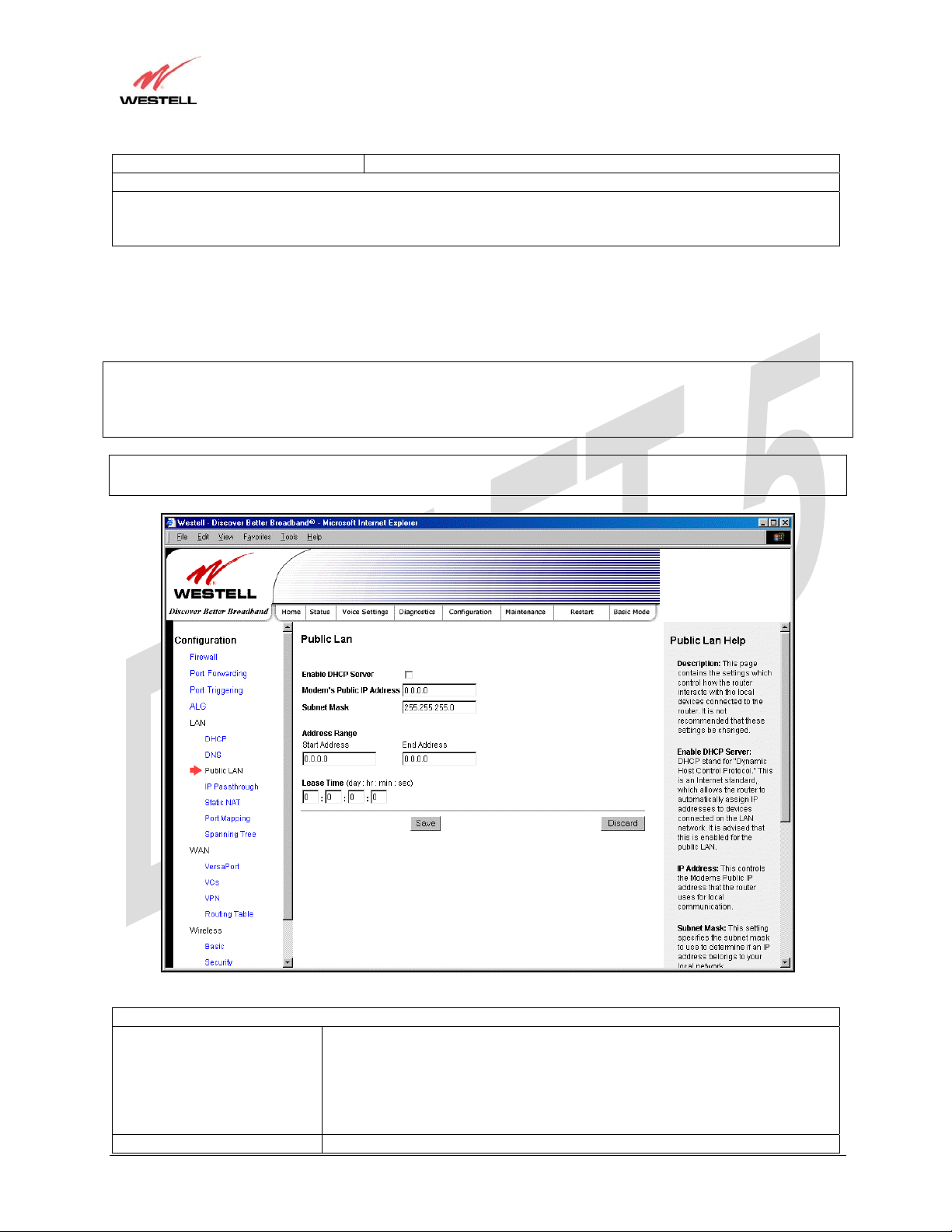
17.5.3 Public LAN – Multiple IP Address Passthrough
The following screen will be displayed if you select LAN > Public LAN from the Configuration menu.
NOTE: Selecting Public LAN will enable the VersaPort™2 port to function as an Ethernet LAN port allowing your
Router to use LAN IP addresses that accessible from the WAN. This allows your computer to have global address
ability. To use the Public LAN feature on the Router, your ISP must support Public LAN and Static IP. Contact your
ISP for details. When VersaPort™2 is configured for Public LAN, the Router’s DSL transceiver will be enabled.
Important: By enabling the Public LAN DHCP Server, you automatically disable the Private LAN DHCP Server on
your Router.
Public LAN Settings
Enable DHCP Server Factory Default = Disable
Possible Response:
If Enabled (box is checked), this will enable the Public LAN DHCP server and
allow IP address to be server from the DHCP Public LAN pool.
If Disabled (the box is unchecked), this will disable the Public LAN DHCP
server.
Modem’s Public IP Address The Router’s public IP address
030-300445 Rev. A 72 June 2005

TriLink Gateway – Draft 5
030-300445 Rev. A
6/22/05
TriLink Gateway (Models 427V10, 427V11)
User Guide
Subnet Mask The Subnet Mask, which determines what porti o n of an IP address is controlled
by the network and which portion is controlled by the host.
Address Range
DHCP Start Address Displays the first IP address that the Public LAN DHCP Server will provide.
The DHCP Start Address must be within the IP address and lower than the
DHCP End Address.
DHCP End Address Displays the last IP address that the Public LAN DHCP Server will provide.
The DHCP End Address must be within the IP address and higher than the
DHCP Start Address.
DHCP Lease Time Factory Default = 01:00:00:00
Displays the amount of time the provided addresses will be valid, after which
time the Public LAN DHCP client will usually re-submit a request.
NOTE: DHCP Lease Time is displayed in the format (day:hour:min:sec)*. This
value must be greater than 10 seconds. Seconds must be between 0 and 59,
minutes must be between 0 and 59, and hours must be between 0 an d 23.
If the settings you have entered in the Public LAN Settings fields are incorrect, the following warnings messages
may be displayed via pop-up screens. If this occurs, check the Public LAN settings.
Warning Message Check Public LAN DHCP Settings
Start Address is not part of the Subnet Check the value in the DHCP Start Address field
End Address is not part of the Subnet Check the value in the DHCP End Address field
End Address is below the Start Address Check the value in the DHCP End Address field
Lease time must be greater than 10 seconds Check the values in the DHCP Lease Time fields
Seconds must be between 0 and 59 Check the Seconds field at DHCP Lease Time
Minutes must be between 0 and 59 Check the Minutes field at DHCP Lease Time
Hours must be between 0 and 23 Check the Hours field at DHCP Lease Time
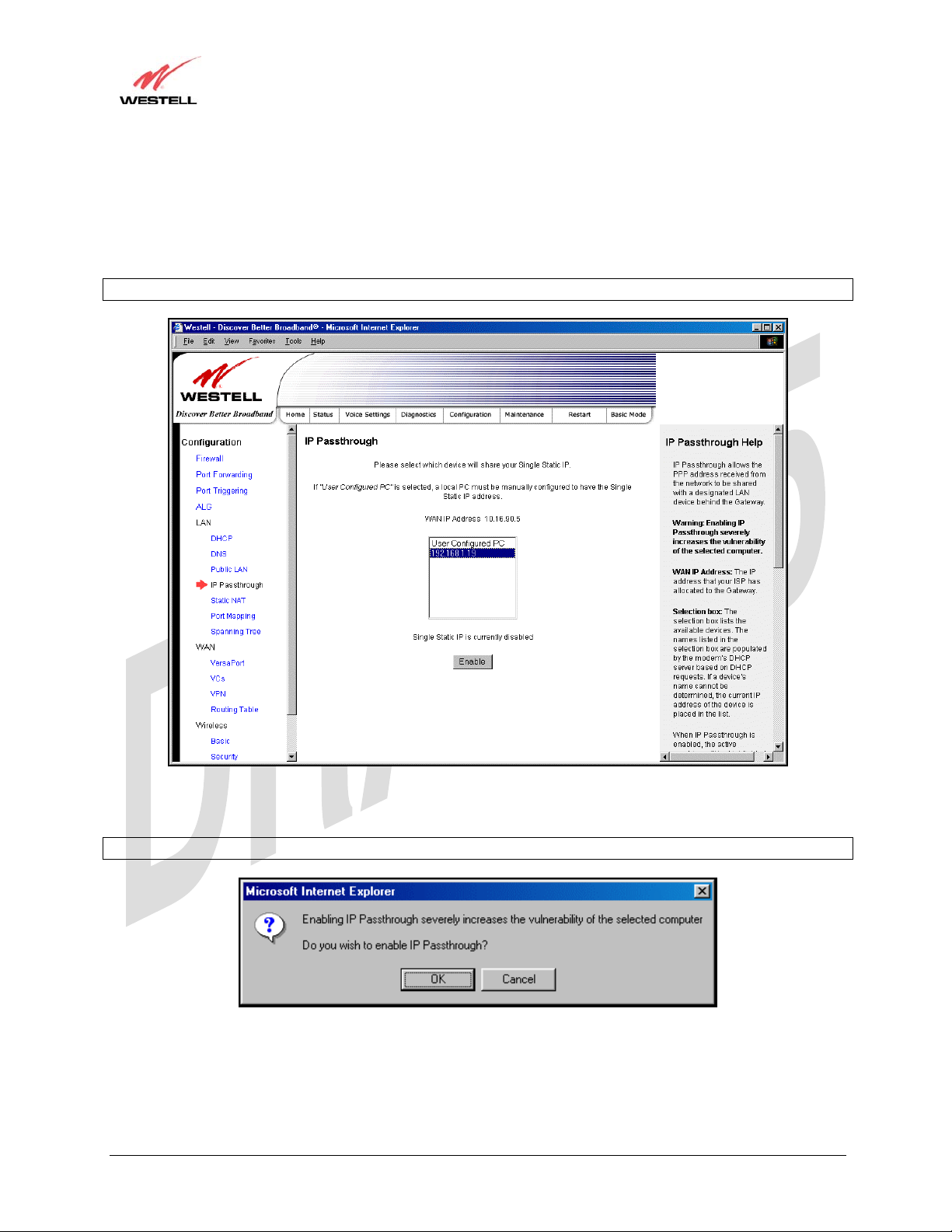
17.5.4 IP Passthrough – Single IP Address Passthrough
IP Passthrough enables you to select the device on your LAN that will share your Single Static IP address. Before
you begin this section, configure your PC settings to obtain an IP address from your Router automatically. (Refer to
your computer’s Windows® Help screen for instructions.)
NOTE: IP Passthrough enables the user to share the WAN assigned IP address with one device on the LAN. By
doing this, the device with the single static IP address becomes visible on the Internet. Network Address Translation
(NAT) and Firewall rules do not apply to the device configured for IP Passthrough. If you are using Routed IP
protocol, IP Passthrough configuration will not be available.
030-300445 Rev. A 73 June 2005
User Guide
TriLink Gateway – Draft 5
030-300445 Rev. A
6/22/05
TriLink Gateway (Models 427V10, 427V11)
17.5.4.1 Enabling IP Passthrough – Single IP Address PassThrough
(Applicable for PPPoE or PPPoA Connections Only)
To enable IP Passthrough, select a device that will share your Single Static IP from the options listed in the window.
This screen enables you to select the device on your LAN that will share your Single Static IP. Click on enable.
NOTE: The actual device name may differ from the name displayed in this screen.
If you clicked Enable, the following pop-up screen will be displayed. Click OK to continue.
Warning: Enabling IP Passthrough severly increases the vulnerability of the selected computer.
030-300445 Rev. A 74 June 2005
User Guide
TriLink Gateway – Draft 5
030-300445 Rev. A
6/22/05
TriLink Gateway (Models 427V10, 427V11)
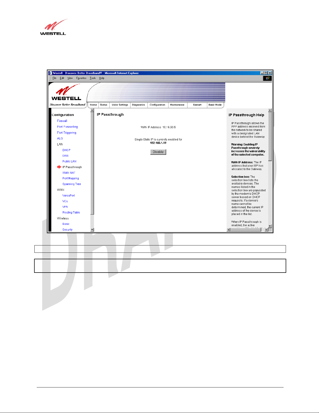
If you clicked OK in the preceding pop-up screen, the Router will be reset and the new configuration will take effect,
as shown in the following screen.
STOP! After you enable IP Passthrough, you must reboot your computer.
NOTE: If you chose to enable User Configured PC, wait for the Router to reset and then manually enter the WAN
IP, Gateway, and Subnet mask addresses you obtained from your Internet service provider into a PC.
030-300445 Rev. A 75 June 2005
User Guide
TriLink Gateway – Draft 5
030-300445 Rev. A
6/22/05
TriLink Gateway (Models 427V10, 427V11)
17.5.4.2 Disabling IP Passthrough – Single IP Address PassThrough
To disable IP Passthrough (if it has been previously enabled), select IP Passthrough from the Configuration>LAN
menu. Click on Disable.
If you clicked Disable following pop-up screen will be displayed. Click OK to continue.
030-300445 Rev. A 76 June 2005

TriLink Gateway – Draft 5
030-300445 Rev. A
6/22/05
TriLink Gateway (Models 427V10, 427V11)
User Guide
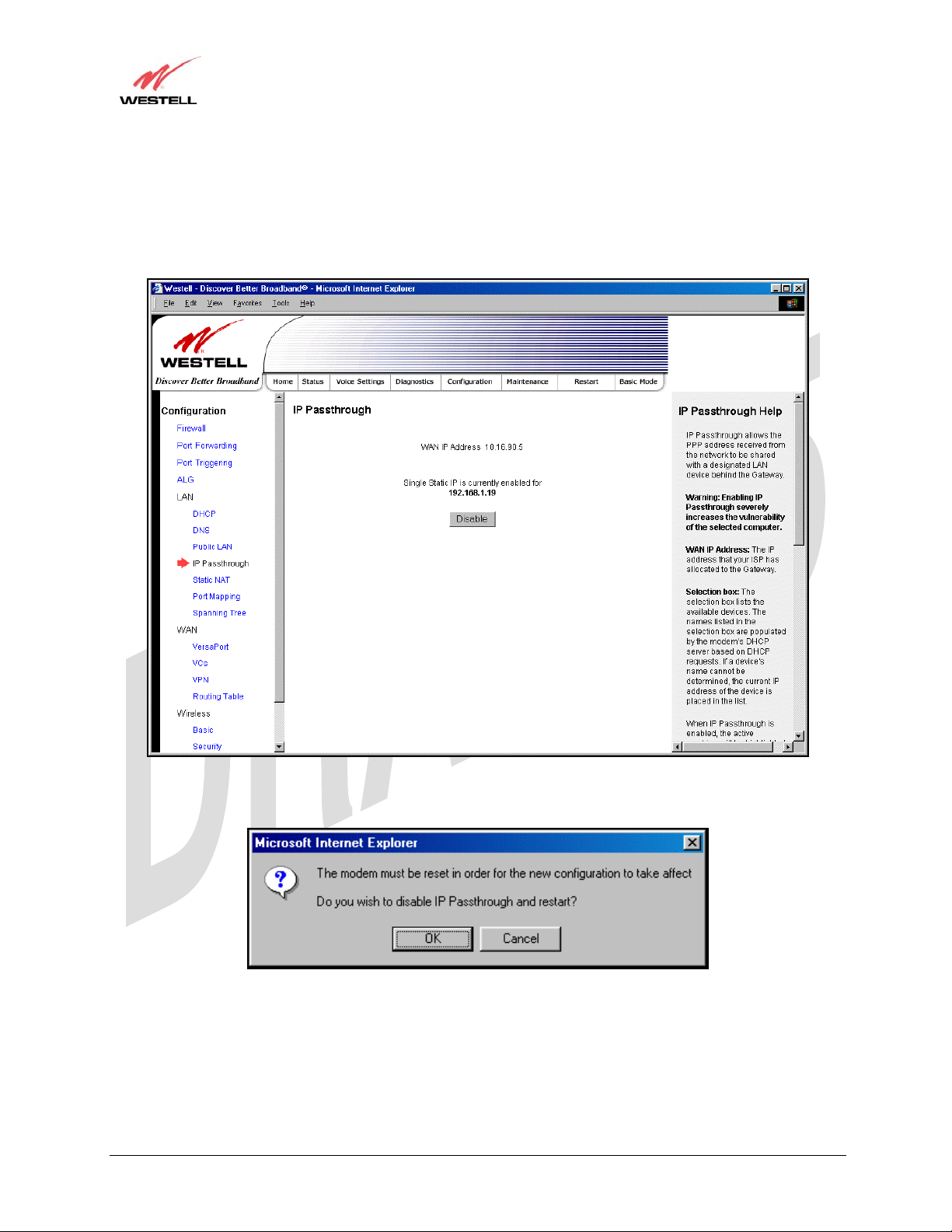
If you clicked OK in the preceding pop-up screen, the following screen will be displayed. The Router will be reset
and the new configuration will take effect.
STOP! After you disable IP Passthrough, you must reboot your computer.
NOTE: If you chose to enable User Configured PC, wait for the Router to reset and then manually enter the WAN
IP, Gateway, and Subnet mask addresses you obtained from your Internet service provider into a PC.
030-300445 Rev. A 77 June 2005
User Guide
TriLink Gateway – Draft 5
030-300445 Rev. A
6/22/05
TriLink Gateway (Models 427V10, 427V11)
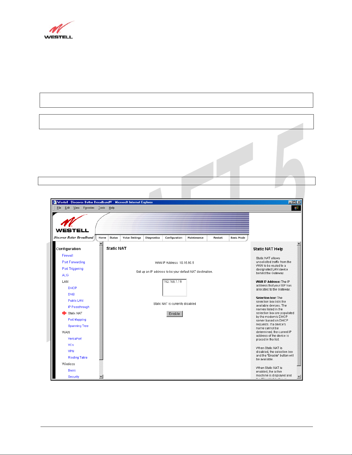
17.5.5 Static NAT
The following screen will be displayed if you select LAN > Static NAT from the Configuration menu. This screen
enables you to configure your Router to work with the special NAT services.
NOTE: When the Router is configured for Static NAT, any unsolicited packets arriving at the WAN would be
forwarded to this device. This feature is used in cases where the user wants to host a server for a specific application.
STOP: IP Passthough must be disabled (if it has been previously enabled) before you enable static NAT. Refer to
section 17.5.4.2 for instructions on disablin g IP Passthr ou g h.
17.5.5.1 Enabling Static NAT
To enable Static NAT, select an IP address or device name from the options listed in the Static NAT screen and then
click Enable.
NOTE: The actual IP addresses or device names may differ from the those displayed in the following screen.
030-300445 Rev. A 78 June 2005
User Guide
TriLink Gateway – Draft 5
030-300445 Rev. A
6/22/05
TriLink Gateway (Models 427V10, 427V11)
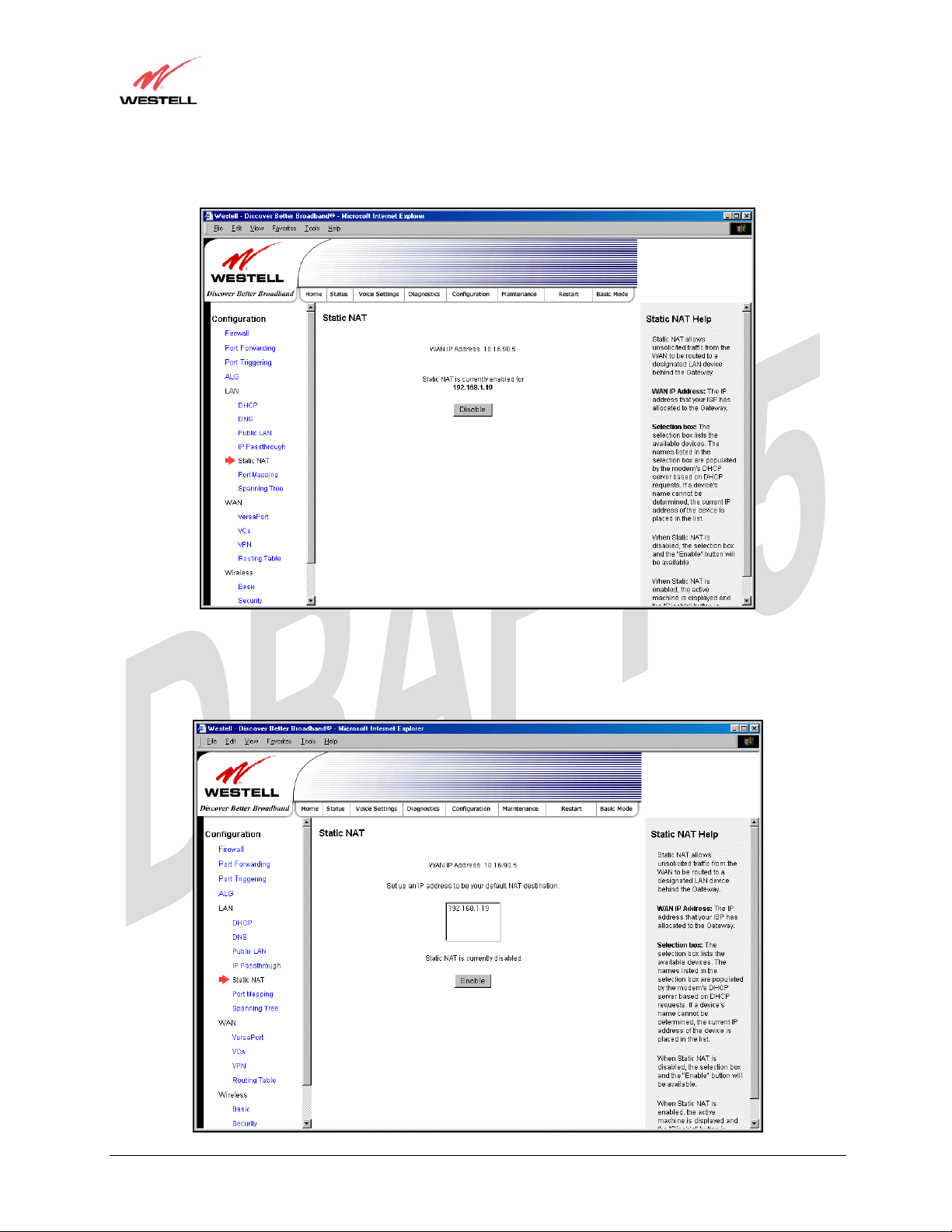
If you clicked Enable, the following screen will be displayed, with Static NAT enabled for the IP address or device
name you selected.
17.5.5.2 Disabling Static NAT
To disable Static NAT, click Disable in the Static NAT screen. The following screen will be displayed.
030-300445 Rev. A 79 June 2005
TriLink Gateway – Draft 5
030-300445 Rev. A
6/22/05
TriLink Gateway (Models 427V10, 427V11)
User Guide
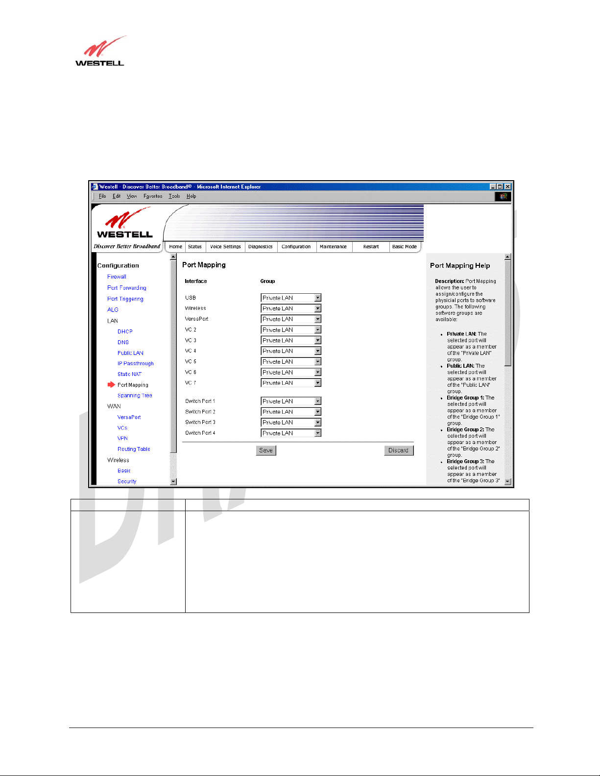
17.5.6 Port Mapping
The following screen will be displayed if you select LAN > Port Mapping from the Configuration menu. This
screen enables you to assign the physical ports to software groups. Enter the appropriate values, and then click save
to save your settings.
Interface The physical ports available for mapping
Group Factory Default: Private LAN
The software defined virtual LAN group to which the port should be assigned:
Possible Responses:
Private LAN
Public LAN
Bridge Group One
Bridge Group Two
Bridge Group Three
Bridge Group Four
030-300445 Rev. A 80 June 2005
 Loading...