

Westell 51062, 51065, 51075, 51080, 61080 Product Manual

PRODUCT M
A
N
UAL
WESTELL.COM
©Westell Technologies. 960-1032-MNL
rE
Bi-directional Amplifiers
510 and 610 Series

Bi-directional Amplifiers
510 and 610 Series
WESTELL.COM
© 2015 Westell Technologies 3 March 2017 Doc. No. 960-1032-MNL rE
1.877.844.4274 Page 2 of 29
Disclaimer
All information and statements contained herein are accurate to the best of the knowledge of Westell, but Westell
makes no warranty with respect thereto, including without limitation any results that may be obtained from the
products described herein or the infringement by such products of any proprietary rights of any persons. Use or
application of such information or statements is at the users’ sole risk, without any liability on the part of Westell.
Nothing herein shall be construed as license or recommendation for use, which infringes upon any proprietary rights
of any person. Product material and specifications are subject to change without notice. Westell’s standard terms
of sale and the specific terms of any particular sale apply.
WARNING. This is NOT a CONSUMER device. It is designed for installation by FCC LICENSEES and QUALIFIED
INSTALLERS. You must have an FCC LICENSE or express consent of an FCC Licensee to operate this
device. Unauthorized use may result in significant forfeiture penalties, including penalties in excess of $100,000 for
Each continuing violation.”
WARNING! Changes and Modifications not expressly approved by Westell can void your authority to operate this
equipment under Federal Communications Commission’s rules.
WARNING! The Manufacturer's rated output power of this equipment is for single carrier operation. For situations
when multiple carrier signals are present, the rating would have to be reduced by 3.5 dB, especially where the
output signal is re-radiated and can cause interference to adjacent band users. This power reduction is to be by
means of input power or gain reduction and not by an attenuator at the output of the device.
. STATE DEPARTMENT EXPORT AUTHORIZATION REQUIRED FOR DISTRIBUTION TO FOREIGN DESTINATIONS OR FOREIGN PERSONS
This document contains Technical Data controlled under the US International Traffic in Arms Regulations (ITAR), 22 CFR 120-130, and may not be exported or transferred
to any Foreign Person, foreign country or foreign entity, by any means, without prior written approval from the U.S. Department of State, Directorate of Defense Trade
Controls (“DDTC”) and DRS ICAS, LLC.

Bi-directional Amplifiers
510 and 610 Series
WESTELL.COM
© 2015 Westell Technologies 3 March 2017 Doc. No. 960-1032-MNL rE
1.877.844.4274 Page 3 of 29
TABLE OF CONTENTS
Disclaimer ........................................................................................................................................................................................................ 2
Preface ........................................................................................................................................................................... 6
Purpose............................................................................................................................................................................................................. 6
Application ...................................................................................................................................................................................................... 6
Product Registration Information .......................................................................................................................................................... 6
Safety Guidelines .......................................................................................................................................................................................... 6
Important Safety Information .................................................................................................................................................................. 7
1 Overview ............................................................................................................................................................... 9
1.1 Product Information ..................................................................................................................................................................... 9
1.1.1 Bi-Directional Amplifier Mechanical and Electrical Specifications, 510 and 610 Series .................................. 10
1.2 LED Indicators ............................................................................................................................................................................... 11
1.3 Pin-Out Chart ................................................................................................................................................................................ 11
2 Product Appearance .......................................................................................................................................... 12
2.1 Mechanical Drawing, Dual-band BDA ................................................................................................................................ 12
3 Installation Tips .................................................................................................................................................. 14
3.1 Important Installation Tips ...................................................................................................................................................... 14
3.2 Multiple Internal Antenna System Design ........................................................................................................................ 14
3.3 Troubleshooting .......................................................................................................................................................................... 15
3.4 Optional Accessories ................................................................................................................................................................. 15
4 LCD Command Interface ................................................................................................................................... 16
4.1 Command Interface Overview ............................................................................................................................................... 16
4.2 The View Menu Series ............................................................................................................................................................... 16
4.2.1 Screen Saver Display .................................................................................................................................................................. 18
4.2.2 Power Readings Display ........................................................................................................................................................... 18
4.2.3 Event Readout Displays ............................................................................................................................................................ 19
4.2.4 Peak Power Readout Display .................................................................................................................................................. 20
4.2.5 Gain Display .................................................................................................................................................................................. 20
4.2.6 BDA Name and Address Display ........................................................................................................................................... 20
4.3 The Edit Menu Series ................................................................................................................................................................. 22
4.3.1 Edit Events Display...................................................................................................................................................................... 23

Bi-directional Amplifiers
510 and 610 Series
WESTELL.COM
© 2015 Westell Technologies 3 March 2017 Doc. No. 960-1032-MNL rE
1.877.844.4274 Page 4 of 29
4.3.2 Edit Peak Power Readout Display ......................................................................................................................................... 23
4.3.3 Edit Downlink Gain Display ..................................................................................................................................................... 23
4.3.4 Edit Uplink Gain Display ........................................................................................................................................................... 24
4.3.5 Edit BDA Name Display ............................................................................................................................................................ 24
4.3.6 Edit BDA Address Display ........................................................................................................................................................ 25
4.3.7 Software Shutdown Display .................................................................................................................................................... 26
4.3.8 Create New Password Display ............................................................................................................................................... 26
5 Registration Numbers ....................................................................................................................................... 28
Appendix A Glossary ............................................................................................................................................ A
TABLE OF FIGURES
Figure 1-1: Product Registration Information ............................................................................................................................................. 6
Figure 2-1: Mechanical Drawing of the Dual-band BDA, including the FCC label ..................................................................... 12
Figure 2-2: Mechanical Drawing of a Single-band BDA, including FCC label .............................................................................. 13
Figure 4-1: View Menu Series .......................................................................................................................................................................... 17
Figure 4-2: Screen Saver Display .................................................................................................................................................................... 18
Figure 4-3: Power Readings Display ............................................................................................................................................................. 18
Figure 4-4: Events Readout Displays ............................................................................................................................................................ 19
Figure 4-5: Peak Power Readout Display .................................................................................................................................................... 20
Figure 4-6: Gain Display ..................................................................................................................................................................................... 20
Figure 4-7: BDA Name and Address Display ............................................................................................................................................. 21
Figure 4-8: Password entry display................................................................................................................................................................ 21
Figure 4-9: Edit Menu Series ............................................................................................................................................................................ 22
Figure 4-10: Edit Events Display ..................................................................................................................................................................... 23
Figure 4-11: Edit Peak Power Readout Display ........................................................................................................................................ 23
Figure 4-12: Edit Downlink Gain Display ..................................................................................................................................................... 24
Figure 4-13: Edit Uplink Gain Display ........................................................................................................................................................... 24
Figure 4-14: Edit BDA name display menu................................................................................................................................................. 25

Bi-directional Amplifiers
510 and 610 Series
WESTELL.COM
© 2015 Westell Technologies 3 March 2017 Doc. No. 960-1032-MNL rE
1.877.844.4274 Page 5 of 29
Figure 4-15: Example display when editing the BDA Name ................................................................................................................ 25
Figure 4-16: Another display when editing the BDA Name ................................................................................................................ 25
Figure 4-17: Edit BDA Address Display ........................................................................................................................................................ 25
Figure 4-18: Software shutdown display ..................................................................................................................................................... 26
Figure 4-19: Old password display ................................................................................................................................................................ 26
Figure 4-20: New password display .............................................................................................................................................................. 27
TABLE OF TABLES
Table 1-1: Model Type/Band Combinations/ Gain Values ................................................................................................................... 10
Table 1-2: Maximum Power Output (dBm) by Model............................................................................................................................ 10
Table 1-3:
General
Specifications*
............................................................................................................................................................... 10
Table 1-4: Pin-Out Descriptions ..................................................................................................................................................................... 11
Table A-1: Acronyms and Abbreviations ....................................................................................................................................................... A
Bi-directional Amplifiers
510 and 610 Series
WESTELL.COM
© 2015 Westell Technologies 3 March 2017 Doc. No. 960-1032-MNL rE
1.877.844.4274 Page 6 of 29
Preface
Purpose
The purpose of this document is to provide instructions to help the experienced technician/engineer install and
commission an in-building wireless enhancement system using Westell Technologies Bi-Directional Amplifiers.
Following the procedures outlined will minimize risks associated with modifying a live system and preclude service
interruptions. This document assumes the technician/engineer understands the basic principles and functionality
involved with repeater and in-building systems and addresses the practical concerns of the installation procedure.
Application
Apply this guide whenever a need exists to add enhanced signal capability to an existing system or when the repeater
is being included in a new installation.
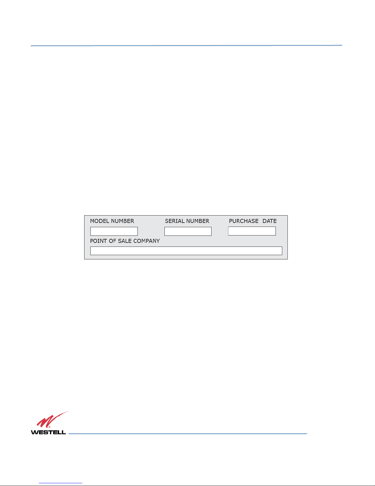
Product Registration Information
The serial number is located on the label on the bottom panel, near the power connectors. Write this number in the
boxes shown in Figure 1-1. Retain this manual, along with proof of purchase, to serve as a permanent record of your
purchase.
Figure 1-1: Product Registration Information
Safety Guidelines
The general safety information in this guideline applies to both operating and service personnel. Specific warnings
and cautions are located in other parts of this manual where they apply, but may not appear in this summary. Failure
to comply with these precautions or specific warnings elsewhere in the manual violates safety standards of design,
manufacture, and intended use of equipment. Westell assumes no liability for the customer’s failure to comply with
these requirements:
Grounding: This bi-directional amplifier is designed to operate from 100-240 VAC and should always be
operated with the ground wire properly connected. Do not remove or otherwise alter the grounding lug on
the power cord.
Explosive atmospheres: To avoid explosion or fire, do not operate this product in the presence of flammable
gases or fumes.
Lightning danger: Do not install or adjust this unit during an electrical storm. Use of a suitable lightning
arrester, such as Westell’s model number CSI-CAP, is strongly recommended.

Bi-directional Amplifiers
510 and 610 Series
WESTELL.COM
© 2015 Westell Technologies 3 March 2017 Doc. No. 960-1032-MNL rE
1.877.844.4274 Page 7 of 29
There are no user-serviceable parts inside. Hazardous voltages are present when the cover is removed. Opening
the chassis will void your warranty. If you suspect a malfunction with this product, call your dealer or Westell’s
Technical Support line at 1-877-844-4274. It is recommended that the unit be powered down when connecting and
disconnecting cables.
Important Safety Information
WARNING! Changes and Modifications not expressly approved by Westell can void your authority to operate this
equipment under Federal Communications Commission’s rules.
An omni-directional antenna with a maximum gain of 3 dBi is authorized for indoor use with these units. The
maximum rated mean output power is 30dBm for the Cell band models therefore the maximum ERP is 2 watts or
less for all units. Inside antennas must be positioned to observe minimum separation of 20 cm (~8 in) from all users
and bystanders. For the protection of personnel working in the vicinity of inside (downlink) antennas, the following
guidelines for minimum distances between the human body and the antenna must be observed.
Under normal conditions, no personnel can come within 20 cm (~ 8 in) from any inside antenna during the installation
of an indoor antenna. This minimum separation will ensure that the employee or bystander does not receive RFexposure beyond the maximum permissible exposure according to section 1.1310 i.e. limits for general
population/uncontrolled exposure.
For outdoor use, a directional antenna up to a maximum gain of 7.5 dBi is authorized for use with this unit. The
outside antenna must be positioned to observe minimum separation of 120 cm (~4 ft) from all users and bystanders.
For the protection of personnel working in the vicinity of outside (uplink) antennas, the following guidelines for
minimum distances between the human body and the antenna must be observed.
The installation of an outdoor antenna must be such that, under normal conditions, no personnel can come within
120 cm (~ 4 ft) from the outside antenna. In all installations, the antenna should never be mounted such that the
main beam is directed toward an area where workers or bystanders may be present. Exceeding this minimum
separation will ensure that the worker or bystander does not receive RF-exposure beyond the maximum permissible
exposure according to section 1.1310 i.e. limits for general population/uncontrolled exposure.
The guidelines for the uplink outdoor antenna are not applicable to the P9 paging model since it is not bi-directional.
The P9 only amplifies the downlink in a nominal bandwidth of 2 mhz from 929-931 mhz.

Bi-directional Amplifiers
510 and 610 Series
WESTELL.COM
© 2015 Westell Technologies 3 March 2017 Doc. No. 960-1032-MNL rE
1.877.844.4274 Page 8 of 29
Renseignements importants en matière
Avertissement ! Changements et Modifications non expressément approuvées par Westell peuvent annuler votre
droit d’utiliser cet appareil en vertu des règles de la Federal Communications Commission.
Une antenne omnidirectionnelle avec un gain maximum de 3 dBi est autorisée pour un usage intérieur avec ces
unités. La puissance de sortie moyenne nominale maximale est 30dBm pour la bande cellulaire des modèles donc
la P.A.R. maximale est de 2 watts ou moins pour toutes les unités. À l’intérieur d’antennes doivent être positionnés
pour observer une distance minimale de 20 cm (8 po) de tous les utilisateurs et les passants. Pour la protection du
personnel travaillant à proximité de l’intérieur (liaison descendante) antennes, les lignes directrices suivantes pour
des distances minimales entre le corps humain et de l’antenne doivent être respectées.
Dans des conditions normales, aucuns personnel ne peuvent venir en moins de 20 cm (~ 8 in) de l’un à l’intérieur
de l’antenne lors de l’installation d’une antenne intérieure. Cette séparation minimale veillera à ce que l’employé
ou le spectateur ne reçoit pas de RF-exposition au-delà de l’exposition maximale admissible conformément à
l’article 1.1310 c'est-à-dire limite pour exposition population générale/non contrôlée.
Pour l’extérieur, une antenne directionnelle jusqu'à un gain maximum de 11 dBi est autorisée pour une utilisation
avec cet appareil. L’antenne extérieure doit être placé pour observer une distance minimale de 1,20 mètre (4 pi) de
tous les utilisateurs et les passants. Pour la protection du personnel travaillant à proximité d’antennes extérieures
de (liaison montante), respecter les directives suivantes pour des distances minimales entre le corps humain et
l’antenne.
L’installation d’une antenne extérieure doit être telle que, dans des conditions normales, aucuns personnel ne
peuvent venir moins de 120 cm (~ 4 pi) de l’antenne extérieure. Dans toutes les installations, l’antenne ne doit
jamais être monté tel que le faisceau principal est dirigé vers une zone où les travailleurs ou les spectateurs
peuvent être présents. Dépassant cette séparation minimale veillera à ce que le travailleur ou le spectateur ne
reçoit pas de RF-exposition au-delà de l’exposition maximale admissible conformément à l’article 1.1310 c'est-àdire limite pour exposition population générale/non contrôlée.
Les lignes directrices pour l’antenne extérieure de liaison montante ne sont pas applicables au modèle P9
pagination puisqu’il n’est pas bidirectionnelle. Le P9 ne fait qu’amplifier la liaison descendante dans une largeur de
bande nominale de 2 mhz à partir de 929-931 mhz.

Bi-directional Amplifiers
510 and 610 Series
WESTELL.COM
© 2015 Westell Technologies 3 March 2017 Doc. No. 960-1032-MNL rE
1.877.844.4274 Page 9 of 29
1 Overview
1.1 Product Information
Westell developed the Bi-Directional Amplifier (BDA) for use in enclosed structures where sufficient signal from local
cell sites to operate cell phones was unavailable within the building. Sufficient signal must be available on the roof
of the structure. The BDA is connected to an external antenna, usually on the roof, and to one or more internal
antennas placed strategically throughout the area where phone service is desired.
The external antenna is usually a directional type such as a yagi. Internal antennas are usually omnidirectional,
although various other types may be used for certain installations. The BDA amplifies both the uplink (phone to
tower) and downlink (tower to phone) signals thus facilitating communications to and from the local cell site.
There are seven amplification stages on the downlink and seven on the uplink for a total of 65 to 80 dB nominal gain
for each link. Gain can be set using the LCD display and pressing the up and down buttons. There are also LED
indicators on the top cover for power overload and gain reduction to prevent oscillation.
WARNING FOR PUBLIC SAFETY MODELS
The bi-directional amplifier (BDA) is not a consumer device. This product is
designed for installation by FCC licensees and qualified users. You must have an
FCC LICENSE or express consent of an FCC Licensee to operate this device. You
must register class B signal boosters (as defined in 47 CFR 90.219) online at
www.fcc.gov/signal-boosters/registration. Unauthorized use may result in
significant forfeiture penalties, including penalties in excess of $100,000 for each
continuing violation.
 Loading...