

Page 1
W.E.ST.
Technical Documentation
POS-124-A-PDP
POS-124-I-PDP
Two axes positioning and synchronisation control module with
integrated profibus interface and SSI sensor interface
Elektronik GmbH
Page 2

W.E.ST.
1 General Information ............................................................................................................................................. 4
1.1 Order number .............................................................................................................................................. 4
1.2 Scope of supply ........................................................................................................................................... 4
1.3 Accessories ................................................................................................................................................. 4
1.4 Symbols used .............................................................................................................................................. 5
1.5 Using this documentation ............................................................................................................................ 5
1.6 Legal notice ................................................................................................................................................. 5
1.7 Safety instructions ....................................................................................................................................... 6
2 Characteristics ..................................................................................................................................................... 7
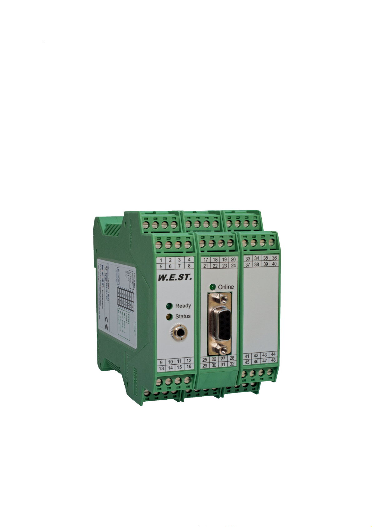
2.1 Device description ....................................................................................................................................... 8
3 Use and application ............................................................................................................................................. 9
3.1 Installation instructions ................................................................................................................................ 9
3.2 Typical system structure ............................................................................................................................ 10
3.3 Method of operation ................................................................................................................................... 10
3.4 Commissioning .......................................................................................................................................... 12
4 Technical description ......................................................................................................................................... 13
4.1 Input and output signals ............................................................................................................................. 13
4.2 LED definitions ........................................................................................................................................... 14
4.3 Circuit diagram ........................................................................................................................................... 15
4.4 Typical cabling ........................................................................................................................................... 16
4.5 Connection examples ................................................................................................................................ 16
4.6 Technical data ........................................................................................................................................... 17
5 Parameters ........................................................................................................................................................ 18
5.1 Parameter overview ................................................................................................................................... 18
5.2 Parameter description ................................................................................................................................ 20
5.2.1
LG (Changing the language for the help texts) ................................................................................. 20
5.2.2
PDPADR (Profibus adress) ............................................................................................................... 20
5.2.3
MODE (Switching between parameter groups) ................................................................................. 20
5.2.4
SENS (Module monitoring) ............................................................................................................... 21
5.2.5
STROKE1 /STROKE2 (Full stroke) ................................................................................................... 21
5.2.6
VRAMP1 /VRAMP2 (Ramp time for external speed demand) .......................................................... 21
5.2.7
VMODE1 / VMODE2 (Switching over the control mode)................................................................... 22
5.2.8
VMAX1 / VMAX2 (Maximum speed in NC Mode) ............................................................................. 22
5.2.9
POL1 / POL2 (Output polarity) .......................................................................................................... 23
5.2.10 EOUT1 / EOUT2 (Output signal in case of error) .............................................................................. 23
5.2.11 INPX (Sensor type define) ................................................................................................................ 24
5.2.12 SSI:OFFSET (Sensor offset) ............................................................................................................. 24
5.2.13 SSI:POL (Direction of the sensor signal) ........................................................................................... 24
5.2.14 SSI:RES (Signal resolution) .............................................................................................................. 25
5.2.15 SSI:BITS (Number of bits) ................................................................................................................. 25
5.2.16 SSI:CODE (Signal coding) ................................................................................................................ 25
5.2.17 AIN (Analogue input scaling) ............................................................................................................. 26
5.2.18 A1 / A2 (Acceleration time) ............................................................................................................... 27
5.2.19 D1 / D2 (Deceleration / braking distance) ......................................................................................... 27
5.2.20 V01 / V02 (Loop gain setting) ............................................................................................................. 28
5.2.21 CTRL1 / CTRL2 (Deceleration function characteristic) ..................................................................... 29
5.2.22 GL: P (gain of the synchronization in SDD mode) ............................................................................. 30
5.2.23 GL: V0 (gain of the synchronization in NC mode) ............................................................................. 30
5.2.24 GL:T1 (Time constant of the synchronisation control) ....................................................................... 30
5.2.25 GL:E (Window for the synchronization error) .................................................................................... 30
Elektronik GmbH
CONTENTS
Page 2 of 45 POS-124-*-PDP-1121 13.02.2013
Page 3

W.E.ST.
Elektronik GmbH
5.2.26 HAND1 / HAND2 (Manual speed) ..................................................................................................... 31
5.2.27 MIN / MIN2 (Overlap compensation) ................................................................................................. 32
5.2.28 MAX1 / MAX2 (Limitation) ................................................................................................................. 32
5.2.29 TRIGGER (Response threshold for the MIN parameter) ................................................................... 32
5.2.30 OFFSET1 / OFFSET2 (Zero correction) ............................................................................................ 33
5.2.31 INPOS:S1 / INPOS:S2 (In position window) ...................................................................................... 33
5.2.32 INPOS:D1 / INPOS:D2 (following error window) ............................................................................... 33
5.2.33 PROCESS DATA (Monitoring) .......................................................................................................... 34
6 Appendix ............................................................................................................................................................ 35
6.1 Failure monitoring ...................................................................................................................................... 35
6.2 Troubleshooting ......................................................................................................................................... 35
6.3 Description of the command structure ........................................................................................................ 37
7 Profibus DP interface ......................................................................................................................................... 38
7.1 Profibus functions....................................................................................................................................... 38
7.2 Installation .................................................................................................................................................. 38
7.3 GSD Configuration File .............................................................................................................................. 38
7.4 Description Profibus DP interface .............................................................................................................. 39
7.5 Commands via PROFIBUS ........................................................................................................................ 40
7.5.1
Command map .................................................................................................................................. 40
7.5.2
Definition of the control bits: .............................................................................................................. 41
7.6 DATA send to PROFIBUS ......................................................................................................................... 42
7.6.1
Feedback map ................................................................................................................................... 42
7.6.2
Definition of the status bits: ............................................................................................................... 43
8 Notes.................................................................................................................................................................. 44
Page 3 of 45 POS-124-*-PDP-1121 13.02.2013
Page 4

W.E.ST.
Elektronik GmbH
1 General Information
1.1 Order number
POS-124-A-PDP-11211 triple stage module with digital SSI-interface with analogue ±10 V
differential output, housing width 67,5 mm
POS-124-I-PDP-1121 triple stage module with digital SSI-interface with analogue 4… 20 mA
output, housing width 67,5 mm
Alternative products:
POS-124-A-PDP-S1-1121 double stage module without digital SSI-interface with analogue ±10 V
differential output, 45 mm housing width
POS-124-I-PDP-S1-1121 double stage module without digital SSI-interface with analogue
4… 20 mA output, 45 mm housing width
1.2 Scope of supply
The scope of supply includes the module including the terminal blocks which are a part of the housing.
The Profibus plug, interface cables and further parts which may be required should be ordered separately. This documentation can be downloaded as a PDF file from www.w-e-st.de.
1.3 Accessories
RS232-SO - Programming cable with RS232 interface
USB-SO - Programming cable with USB interface
WPC-300 - Start-Up-Tool (download: www.w-e-st.de/produkte/software)
PDP-Plug - Profibus connector with switchable terminating resistors
1
The number of the version consists of the hardware-version (first two digits) and the software-version (second two
digits). Because of the development of the products these numbers can vary. They are not strictly necessary for the
order. We will always deliver the newest version.
Page 4 of 45 POS-124-*-PDP-1121 13.02.2013
Page 5

W.E.ST.
Elektronik GmbH
1.4 Symbols used
General information
Safety-related information
1.5 Using this documentation
Structure of the documentation:
The standard product is descibed up to chapter 6. The extensions like POWER STAGE or
SSI-INTERFACE are described in the chapters ADDITIONAL INFORMATION.
1.6 Legal notice
W.E.St.
Gewerbering 31
D-41372 Niederkrüchten
Tel.: +49 (0)2163 577355-0
Fax.: +49 (0)2163 577355 -11
Homepage: www.w-e-st.de or www.west-electronics.com
EMAIL: info@w-e-st.de
Date: 13.02.2013
The data and characteristics described herein serve only to describe the product. The user is required to
evaluate this data and to check suitability for the particular application. General suitability cannot be inferred from this document. We reserve the right to make technical modifications due to further development of the product described in this manual. The technical information and dimensions are non-binding.
No claims may be made based on them.
This document is copyright.
Elektronik GmbH
Page 5 of 45 POS-124-*-PDP-1121 13.02.2013
Page 6
W.E.ST.
Elektronik GmbH
1.7 Safety instructions
Please read this document and the safety instructions carefully. This document will help to define the
product area of application and to put it into operation. Additional documents (WPC-300 for the start-up
software) and knowledge of the application should be taken into account or be available.
General regulations and laws (depending on the country: e.g. accident prevention and environmental protection) must be complied with.
These modules are designed for hydraulic applications in open or closed-loop control circuits. Uncontrolled movements can be caused by device defects (in the hydraulic module
or the components), application errors and electrical faults. Work on the drive or the electronics must only be carried out whilst the equipment is switched off and not under pressure.
This handbook describes the functions and the electrical connections for this electronic
assembly. All technical documents which pertain to the system must be complied with
when commissioning.
This device may only be connected and put into operation by trained specialist staff. The
instruction manual must be read with care. The installation instructions and the commissioning instructions must be followed. Guarantee and liability claims are invalid if the instructions are not complied with and/or in case of incorrect installation or inappropriate
use.
CAUTION!
All electronic modules are manufactured to a high quality. Malfunctions due to the failure
of components cannot, however, be excluded. Despite extensive testing the same also
applies for the software. If these devices are deployed in safety-relevant applications,
suitable external measures must be taken to guarantee the necessary safety. The same
applies for faults which affect safety. No liability can be assumed for possible damage.
Further instructions
• The module may only be operated in compliance with the national EMC regulations. It
is the user’s responsibility to adhere to these regulations.
• The device is only intended for use in the commercial sector.
• When not in use the module must be protected from the effects of the weather, con-
tamination and mechanical damage.
• The module may not be used in an explosive environment.
• To ensure adequate cooling the ventilation slots must not be covered.
• The device must be disposed of in accordance with national statutory provisions.
Page 6 of 45 POS-124-*-PDP-1121 13.02.2013
Page 7

W.E.ST.
Elektronik GmbH
2 Characteristics
This electronic module has been developed for controlling hydraulic positioning drives.
Both axes are controlled complete autonomous via the Profibus. Optionally an interconnection to a two
axes synchronised system is intended.
The differential outputs are covered for activation of constant valves with integrated or external
electronics (differential input). Intended is this module for the connection of analogue way sensors 0...10V
or 4...20mA (scalable) or digital SSI sensor interfaces.
The internal control signals operating states and error conditions via Profibus to the higher-level control.
The operation is signaled by a switch output.
Typical applications: Positioning control or synchronization control with hydraulic axes.
Features
• Two independent positioning axes
• Can be combined for synchronization controls
• Command position parameter, actual value response, on loop control byte and status byte via
fieldbus Profibus DP
• Principle of stroke-dependent deceleration for the shortest positioning time or NC profile gen-
erator for constant speed
• Analogue or digital (SSI) actual value registration for both axes
• Superimposed synchronization controller as PT1 actuator
• Usable with zero lapped control valves
• Fault diagnosis and extended function checking
• Simplified parameterization with WPC-300 software version 3.2
Page 7 of 45 POS-124-*-PDP-1121 13.02.2013
Page 8
W.E.ST.
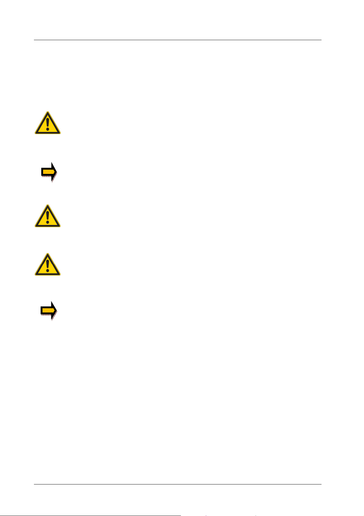
2.1 Device description
Elektronik GmbH
99,0000 mm
D-outputs
Ready
24 V
0 V
Enable
D-inputs
Made in Germany
ID:
V:
W.E. ST.
D-41372 Niederkrüchten
Homepage: http://www.w-e-st.de
1
9
2
10
3
11
4
12
5
13
6
14
15
7
16
8
Add.:Date:
Elektronik
Analogue
GND
GND
Pos. 1
Pos. 2
A
B
Differential
output
Typenschild und Anschlussbelegung
Type plate and terminal pin assignment
LEDs
RS232
Interface
1 2 3 4
5 6 7 8
W.E.ST.
Ready
Status
18 19 2017
22 23 2421
Online
Profibus
9pol SUBD
67,5000 mm
114,0000 mm
34 35 3633
38 39 4037
121,0000 mm
Klemmblöcke (steckbar)
Terminals (removable)
PROFIBUS Buchse
PROFIBUS connector
9 10 11 12
14 15 1613
26 27 2825
30 31 3229
42 43 4441
46 47 4845
Page 8 of 45 POS-124-*-PDP-1121 13.02.2013
Page 9

W.E.ST.
Elektronik GmbH
3 Use and application
3.1 Installation instructions
• This module is designed for installation in a shielded EMC housing (control cabinet). All cables
which lead outside must be screened; complete screening is required. It is also a requirement
that no strong electro-magnetic interference sources are installed nearby when using our control
and regulation modules.
• Typical installation location: 24V control signal area (close to PLC)
The devices must be arranged in the control cabinet so that the power section and the signal section are separate from each other.
Experience shows that the installation space close to the PLC (24 V area) is most suitable. All
digital and analogue inputs and outputs are fitted with filters and surge protection in the device.
• The module should be installed and wired in accordance with the documentation bearing in mind
EMC principles. If other consumers are operated with the same power supply, a star- connected
ground wiring scheme is recommended. The following points must be observed when wiring:
• The signal cables must be laid separately from power cables.
• Analogue signal cables must be shielded.
• All other cables must be screened if there are powerful interference sources (frequen-
cy converters, power contactors) and cable lengths > 3m. Inexpensive SMD ferrites
can be used with high-frequency radiation.
• The screening should be connected to PE (PE terminal) as close to the module as
possible. The local requirements for screening must be taken into account in all cases.
The screening should be connected to at both ends. Equipotential bonding must be
provided where there are differences between the connected electrical components.
• With longer lengths of cable (>10 m) the diameters and screening measures should
be checked by specialists (e.g. for possible interference, noise sources and voltage
drop). Particular care is required with cables of over 40 m in length – the manufacturer
should be consulted if necessary.
• A low-resistance connection between PE and the mounting rail should be provided. Transient in-
terference is transmitted from the module directly to the mounting rail and from there to the local
earth.
• Power should be supplied by a regulated power supply unit (typically a PELV system complying
with IEC364-4-4, secure low voltage). The low internal resistance of regulated power supplies
gives better interference voltage dissipation, which improves the signal quality of high-resolution
sensors in particular. Switched inductances (relays and valve coils connected to the same power
supply) must always be provided with appropriate overvoltage protection directly at the coil.
Page 9 of 45 POS-124-*-PDP-1121 13.02.2013
Page 10
W.E.ST.
Elektronik GmbH
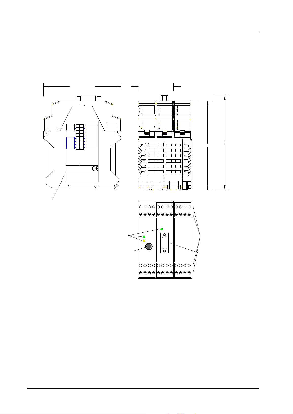
3.2 Typical system structure
This minimal system consists of the following components:
(*1) proportional valve
(*2) hydraulic cylinder
(*3) position sensor
(*4) POS-124-PDP control module
(*5) interface to PLC with analogue and digital signals
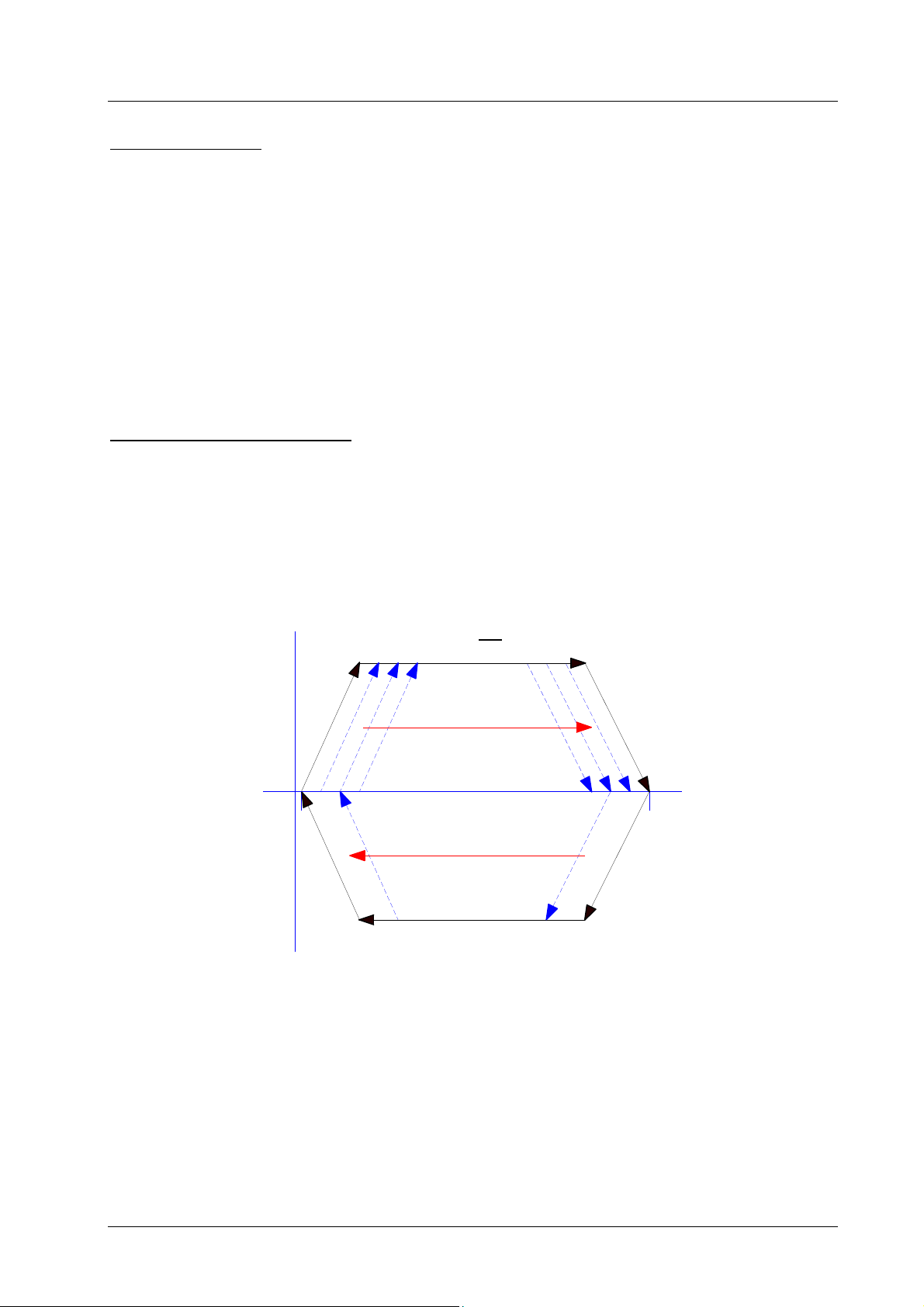
3.3 Method of operation
This control module supports simple point-to-point positioning with hydraulic drives. The system works
based on the principle of stroke-dependent deceleration, i.e. the control gain (deceleration stroke) is set
via parameters D:A and D:B. Alternatively the loop gain will be used in NC mode.
The deceleration characteristics can be set linearly (LIN) or approximately quadratically (SQRT1) via the
CTRL parameter. For normal proportional valves SQRT1 is the input setting.
For control valves with a linear flow curve it depends on the application. If LIN is selected for these valves
a significantly shorter deceleration distance can often be set (D:A and D:B).
Page 10 of 45 POS-124-*-PDP-1121 13.02.2013
Page 11
W.E.ST.
Elektronik GmbH
Positioning sequence:
The positioning is controlled via Profibus. After releasing (ENABLE input), the command
position is set to the actual position of the sensor and the axis stays in closed loop position control
mode. The READY output indicates that the system is generally ready for operation. When setting the
START-signal, the preset command value will be taken over. The axis immediately will drive to this new
command position and indicates reaching it by setting the InPos output.
The InPos output stays active as long as the axis is within the preset InPos window and the START input
is active. The driving velocity is forced by preset parameter, too.
The axis can be driven in manual mode (START is off) using the control bits HAND+ or HAND-. The
velocity is programmable. When the HAND signal is deactivated, the command position is set to the actu-
al position and the system stays in closed loop position control mode.
Setting the synchronous bit (GL) will synchronize both axes and the synchronization controller is overrid-
ing the position controller of axis 2. Axis 2 is now following axis 1 according to the master-slave-principle.
Influences on positioning accuracy:
The positioning accuracy is determined by the hydraulic and mechanical conditions. The right choice of
valve is therefore a decisive factor. In addition, two mutually contradictory requirements (short position
time and high accuracy) must be taken into account when designing the system.
The electronic limitations lie mainly in the resolution of the analogue signals, although with our modules a
resolution of < 0.01% only needs to be considered with long positions. In addition, the linearity of the individual signal points (PLC, sensor and control module) must be considered. The worst-case scenario is
that a system-specific absolute fault occurs.
The repeat accuracy is, however, not affected by this.
V+
A:A D:A
D:B
V+
volumetric flow
MAX:A
control direction
driving out
control direction
driving in
MAX:B
P-A
and B-T
A:B
Page 11 of 45 POS-124-*-PDP-1121 13.02.2013
Page 12

W.E.ST.
3.4 Commissioning
Step Task
Elektronik GmbH
Installation
Switching on for the first
time
Setting up communication
Pre-parameterisation
Control signals
Install the device in accordance with the circuit diagram. Ensure it is wired correctly and that the signals are well shielded. The device must be installed in a metal
protective housing (control cabinet or similar).
Ensure that no unwanted movement is possible in the drive (e.g. switch off the
hydraulics). Connect an ammeter and check the current consumed by the device.
If it is higher than specified there is an error in the cabling. Switch the device off
immediately and check the cabling.
Once the power input is correct the PC (notebook) should be connected to the serial interface. Please see the WPC-300 program documentation for how to set up
communication.
Further commissioning and diagnosis are supported by the operating software.
Now set up the following parameters (with reference to the system design and circuit diagrams):
The STROKE, POSITION, SENSOR SETTING, POLARITY, ACCELERATION
and DECELERATION.
Pre-parameterisation is necessary to minimise the risk of uncontrolled movements.
Parameterise specific settings for the control element (MIN for following error
compensation and MAX for maximum velocity).
Reduce the speed limitation to a value which is uncritical for the application.
Check the control signal with a voltmeter. The control signals (PIN 15 to PIN16
and PIN19 to PIN20) lies in the range of ± 10V. In the current state it should be
0V. Alternatively, if current signals are used, approx. 0 mA should flow.
CAUTION! This signal depends on the EOUT setting.
Profibus communication
Switching on the hydraulics
Activating ENABLE
Activating START
Manual (HAND) operation
Optimise controller
Activate the profibus communication and check whether the right values and bits
are send to the module.
The hydraulics can now be switched on. Since the module is not yet generating a
signal the drive should be at a standstill or drift slightly (leave its position at a slow
speed).
CAUTION! The drive can now leave its position and move to an end position at
full speed. Take safety measures to prevent personal injury and damage.
The drive is in the current position (with ENABLE the actual position is accepted
as the required position). Should the drive move to an end position the polarity is
probably wrong.
With the start signal the demand value on the analogue demand value input is accepted and the axis moves to the predefined target position.
If START is disabled the axis stops in the preset deceleration distance D:S.
If START is disabled the axis can be moved manually with HAND+ or HAND- .
After disabling the HAND signal, the axis stops in a controlled manner at the current position.
Now optimise the controller parameters according to your application and your
requirements.
Page 12 of 45 POS-124-*-PDP-1121 13.02.2013
Page 13

W.E.ST.
4 Technical description
4.1 Input and output signals
Connection Supply
Elektronik GmbH
PIN 3, PIN 31
and PIN 35
PIN 4, PIN 32
and PIN 36
Power supply (see technical data)
0 V (GND) connection.
Caution, PIN 4 is connected internally to PIN 11 (and also possibly to PIN 12 depending on
the model). These connections serve as a reference potential for the analogue sensor or
demand value signals.
Connection Analogue signals
PIN 13
PIN 14
PIN 15 / 16
PIN 19 / 20
Analogue position actual value (X1), range 0… 100% corresponds to 0… 10V or 4… 20 mA
Analogue position actual value (X2), range 0… 100% corresponds to 0… 10V or 4… 20 mA
Analogue differential output for activation of the axis 1:
-100...100% corresponds to -10...10V.
Analogue differential output for activation of the axis 2:
-100...100% corresponds to -10...10V.
Connection SSI sensors
PIN 37-40
PIN 33, 34
PIN 41-44
PIN 47, 48
Interface 1 to the SSI sensor. RS422 interface and power supply
Interface 2 to the SSI sensor. RS422 interface and power supply
Connection Digital inputs and outputs
PIN 8
PIN 2
PIN 1
Enable input:
This digital input signal initializes the application. The signal will be approved in connection
with the software enable the corresponding axis.
Synchronous error output (only active in synchronous mode):
ON: Slave axis within the error window (GL:E)
OFF: Slave axis outside the error window (GL:E)
READY output:
ON: The module is enabled; there are no discernable errors.
OFF: Enable (PIN 8) is disabled or an error (sensor or internal error) has been detected.
Page 13 of 45 POS-124-*-PDP-1121 13.02.2013
Page 14

W.E.ST.
Elektronik GmbH
4.2 LED definitions
LEDs Description of the LED function
GREEN
YELLOW
GREEN
(right side)
Identical to the READY output.
OFF: no power supply or ENABLE is not activated
ON: System is ready for operation
Flashing: Error discovered (valve solenoid or 4… 20 mA).
The error of one axis results to a flashing LED.
Only active in synchronous mode:
OFF: Slave axis outside the error window
ON: Slave axis within the error window
Profibus connection.
OFF: No Profibus communication
ON: Profibus communication in prozess
Page 14 of 45 POS-124-*-PDP-1121 13.02.2013
Page 15

W.E.ST.
4.3 Circuit diagram
Elektronik GmbH
Profibus DP
ANA Feedback
Position 1
0 V
SSI Feedback
Position 1
0..10V
4..20mA
0 V
DC
24 V
0 V
35
31
3
4
24 V
0 V
PELV
32
36
15
Differentialinput
16
Profibus
SUBD
9
9polig
ws1
v1
Speed
Profil Generator
Commands:
- STROKE
VMODE = NC
Speed
via Feldbus
Position
via Feldbus
POS-124-A/I-PDP
Control Function
xd1w1
Commands:
- A:A and A:B
- D:A and D:B
-
Internal Power
VMODE = SDD
Output
limitation
Output Adaptation
Commands:
- MIN: A and B
- MAX: A and B
- TRIGGER
- OFFSET
- POL
DC
Output: A
u1
Output: B
12
Input Scaling
13
Commands:
11
AIN:W
33
24 V
SSI Sensor
Commands:
34
0 V
SSI:RES
SSI:BITS
SSI:CODE
37
CLK+
SSI:POL1
SSI:OFFSET1
38
CLK-
39
DATA+
40
DATA-
VMODE = SDD
INPX = ANA
INPX = SSI
x1
x1
x2
AXIS 1
Synchronous Controller
Commands:
- GL:P
- GL:T1
- GL:E
Enable Sync.
via Feldbus
I-Version: 4... 20 mA
PIN 15 = +, PIN 12 = GND
ANA Feedback
Position 2
0 V
SSI Feedback
Position 2
Enable
0..10V
4..20mA
0 V
Input Scaling
14
Commands:
11
AIN:W
47
24 V
SSI Sensor
Commands:
48
0 V
SSI:RES
SSI:BITS
SSI:CODE
41
CLK+
SSI:POL2
SSI:OFFSET2
42
CLK-
43
DATA+
44
DATA-
8
24 V input
x2
INPX = ANA
x2
INPX = SSI
Commands:
- TS (sample time)
- MODE (Expert or Standard)
- EOUT (Error Mode)
- INPOS (InPos output)
AXIS 2
Control program
RS232 C
9600 Baud
1 Stopbit
no parity
3,5 mm JISC-6560 Buchse
u2
24 V output
24 V output
Output: A
Output: B
PE via DIN-RAIL
19
Differentialinput
20
18
I Version: 4... 20 mA
PIN 19 = +, PIN 18 = GND
Ready
1
2
Synchron
Error
Page 15 of 45 POS-124-*-PDP-1121 13.02.2013
Page 16

W.E.ST.
4.4 Typical cabling
ENABLE
4321
Elektronik GmbH
20191817
power
24V
0V
supply
+/- 10 V (4...20mA)
to control valve 2
+24 V DC
GND
SSI 1
36353433
sensor interface
CLK+
CLKDATA+
DATA-
PE
0..10V, 4..20mA
sensor position
13 = X1, 14 = X2
+/- 10 V (4...20mA)
to control valve 1
4.5 Connection examples
SPS / PLC 0... 10 V speed input signal
+In PIN 10
-In PIN 9
GND PIN 11
24
8765
1211109
16151413
232221
Profibus
9pol Buchse
32313029
393837
40
44434241
48474645
GND
power supply
communication modul
+24 V DC
PE Klemme
DATADATA+
CLKCLK+
SSI 2
sensor interface
GND
+24 V DC
z. B. 24 V
PLC or sensor with 4... 20 mA (two wire connection)
+In PIN 13 or 14
PIN 12 (GND)
AIN:W 2000 1600 2000 C ( für 0... 100%)
SPS / PLC 0... 10 V command and feedback signal
+In PIN 13 or PIN 14
In PIN 12 (GND)
z. B. 24 V
PLC or sensor with 4... 20 mA (three wire connection)
+In PIN 13 or 14
PIN 12 (GND)
AIN:W 2000 1600 2000 C ( für 0... 100%)
Valve (6 + PE plug) with OBE electronics
Module
PIN 12
PIN 15
PIN 16
A : 24 V supply
B : 0 V supply
C : GND or enable
D : + differential input
E : - differential input
F : diagnostics
PE -
Page 16 of 45 POS-124-*-PDP-1121 13.02.2013
Page 17

W.E.ST.
4.6 Technical data
Supply voltage
Current requirement
External protection
Digital inputs
Input resistance
Digital outputs
Analogue inputs (sensor and
demand value signal)
Signal resolution
[VDC]
[mA]
[A]
[V]
[V]
[kOhm]
[V]
[V]
[V]
[mA]
[%]
24 (±10 %)
500
1 medium time lag
logic 0: < 2 V
logic 1: > 10 V,current consumption
< 0,1 mA
25
logic 0: < 2 V
logic 1: > 12 V; max. 10 mA
0… 10. 33 kOhm
4… 20. 250 Ohm
0.01(internally 0.0031) inc. oversampling
Elektronik GmbH
[V]
[mA]
[%]
[mA]
[%]
[ms]
[°C]
[°C]
[%]
[kg]
2 x 0… 10; Differential output
5 (max. load)
0.024
4… 20; 390 Ohm maximum load
0.024
-
RS-422 Spezifikation, 150 kBaud
1
RS 232C, 9600… 57600 Baud, 1 stop
bit, no parity, Echo Mode
9.6,19,2,93.75,187.5,500,1500,3000
6000, 12000 kbits/s
1810h
Snap-on module to EN 50022
PA 6.6 polyamide
Flammability class V0 (UL94)
IP20
-10… 50
-20... 70
<95 (non-condensing)
RS232: 3,5mm JISC-6560
11 x 4-pole terminal blocks
Profibus DP, D-Sub 9 pol.
PE: via the DIN mounting rail
EN 61000-6-2: 8/2002
EN 61000-6-3: 6/2005
0,375
Analogue outputs
Voltage
Signal resolution
Current
Signal resolution
SSI interface
Controller sample time
Serial interface
Profibus DP
Baud rate
ID Number
Housing
Protection class
Temperature range
Storage Temperature
Humidity
Connections
EMC
Weight
Page 17 of 45 POS-124-*-PDP-1121 13.02.2013
Page 18

W.E.ST.
5 Parameters
5.1 Parameter overview
Command
Default
Unit
Elektronik GmbH
Description
LG
PDPADR
MODE
SENS
INPX
STROKE1
STROKE2
VRAMP1
VRAMP2
VMODE1
VMODE2
VMAX1
VMAX2
POL1
POL2
EOUT1
EOUT2
SSI:OFFSET1
SSI:OFFSET2
SSI:POL1
SSI:POL2
SSI:RES
SSI:BITS
SSI:CODE
AIN:I
A
B
C
X
A1:I
A2:I
D1:I
D2:I
V01:I
V02:I
CTRL 1
CTRL 2
GL:P
GL:T1
GL:E
HAND1:I
HAND2:I
GB -
126 -
STD -
ON -
SSI -
X = 10...10000 mm
100 ms
SDD -
50 mm/s
+ -
0 0,01%
0 10 nm
+ -
500 10 nm
24 -
GRAY -
10000
10000
10000
:A 100
:B 100
:A 25
:B 25
:S 10
:A 10
:B 10
sqrt1 -
:A 3330
:B -3330 0,01%
V
48
80
200
-
0,01 %
-
ms
mm
mm
mm
1/s
1/s
0,01
ms
µm
Changing language help texts.
Address of the unit at the Profibus.
Mode parameter.
Activation and disabling of internal failure monitoring functions.
Switching between SSI and analog sensors.
Working stroke of the sensor.
Ramp function for external speed input.
Control structure for positioning process.
Maximum speed in NC mode.
Reversal of output polarity.
Error output signal.
Position offset
Sensor polarity
Resolution of the sensors (the same for both)
Number of transmitted bits (the same for both)
transfer Encoding (the same for both)
Analogue input scaling for X1 and X2.
Acceleration times.
Deceleration distance
Deceleration distance
Emergency deceleration distance
Loop gain setting.
Specification of control characteristics.
Definition of the synchronization actuator. GL:P
adjusted the gain, GL:T1 effects a decelerated action of the actuator (revised stability) and .GL:E for
error-window in synchronous run (out of window
GL-Error-Bit is set on the Profibus)
Output signal in manual mode.
Page 18 of 45 POS-124-*-PDP-1121 13.02.2013
Page 19

W.E.ST.
Elektronik GmbH
MIN1:I
MIN2:I
MAX1:I
MAX2:I
TRIGGER1
TRIGGER2
OFFSET1
OFFSET2
INPOS1:I
INPOS2:I
0
0
10000
10000
200
200
0
0
200
200
0,01 %
0,01 %
0,01 %
0,01 %%
0,01 %
0,01 %%
0,01 %
0,01 %%
µm
µm
Zero point setting /following error compensation.
Maximum output signal limitation.
Trigger threshold for activating the following error
compensation (MIN).
Offset value (added to the output signal).Axis 1 and
axis 2 separate definable.
Range for InPos signal.
Page 19 of 45 POS-124-*-PDP-1121 13.02.2013
Page 20

W.E.ST.
Elektronik GmbH
5.2 Parameter description
5.2.1 LG (Changing the language for the help texts)
Command
LG x x= DE|GB -
Either German or English can be selected for the help texts.
CAUTION: After changing the language settings the ID button (SPEED BUTTON) in the menu
bar (WPC-300) must be pressed (module identification).
Parameters
Unit
5.2.2 PDPADR (Profibus adress)
Command
PDPADR X x= 1...126 -
Slave address in the Profibus network.
Parameters
Unit
5.2.3 MODE (Switching between parameter groups)
Group
STD
Group
STD
Command
MODE x x= STD|EXP -
This command changes the operating mode. Various commands (defined via STD/EXP) are blanked out
in Standard Mode. The commands in Expert Mode have a more significant influence on system behaviour
and should accordingly be changed with care.
Parameters
Unit
Group
STD
Page 20 of 45 POS-124-*-PDP-1121 13.02.2013
Page 21

W.E.ST.
5.2.4 SENS (Module monitoring)
Elektronik GmbH
Command
SENS x x= ON|OFF -
Parameters
Unit
Group
STD
This command is used to activate and disable monitoring functions (4… 20 mA sensors and internal
module monitoring).
ON: Monitor function is activ.
OFF: Failures are ignored.
Normally, monitoring is always active as otherwise no errors are signalled via the PIN 1
(READY) output. It can, however, be disabled for fault finding.
5.2.5 STROKE1 /STROKE2 (Full stroke)
Command
STROKE1 X
STROKE2 X
Parameters
x= 10… 10000 mm
Unit
Group
STD
This command defines the full stroke, which corresponds to 100% of the input signal. If the demand is set
incorrectly, this leads to incorrect system settings, and the dependent parameters such as speed and
gain cannot be calculated correctly.
5.2.6 VRAMP1 /VRAMP2 (Ramp time for external speed demand)
Command
VRAMP1 X
VRAMP2 X
The rate of change of the external speed demand can be limited by this ramp time. The command is only
active if external speed demand (VS = EXT) has been parametrised.
Parameters
x= 1… 2000 ms
Unit
Group
STD
Page 21 of 45 POS-124-*-PDP-1121 13.02.2013
Page 22

W.E.ST.
Elektronik GmbH
5.2.7 VMODE1 / VMODE2 (Switching over the control mode)
Command
VMODE1 X
VMODE2 X
Parameters
x= SDD|NC
Unit
Group
EXP
The fundamental control structure can be changed with this parameter.
SDD: Stroke-Dependent Deceleration. In this mode, stroke-dependent deceleration is activated. This
mode is the default mode and is suitable for most applications. With stroke-dependent deceleration the drive comes to a controlled stop at the target position. From the set deceleration
point the drive then switches to control mode and moves accurately to the desired position.
This control structure is very robust and reacts insensitively to external influences such as fluctuating pressures.
One disadvantage is that the speed varies with the fluctuating pressure as the system runs
under open-loop control.
NC: Numerically Controlled. In this mode a position profile is generated internally. The system al-
ways works under control and uses the following error to follow the position profile. The magnitude of the following error is determined by the dynamics and the set control gain. The advantage is that the speed is constant (regardless of external influences2) due to the profile
demand. Because of continuous control, it is necessary not to run at 100% speed, as otherwise the errors cannot be corrected. 80% of the maximum speed is typical although especially
the system behaviour and the load pressure should be taken into account when specifying the
speed.
5.2.8 VMAX1 / VMAX2 (Maximum speed in NC Mode)
Command
VMAX1 X
VMAX2 X
Specification of the maximum speed in NC Mode. This value is defined by the drive system and should be
specified as precisely as possible (not too high under any circumstances)3. The maximum speed is
scaled by means of the VELO value or via the external speed demand. The command is only active if the
VMODE has been parametrised to NC.
2
There are deviations due to external influences which are then compensated for. The time response is defined by
the system dynamics.
3
If the retraction speed and the outward speed are different, the smaller one has to be used
Parameters
x= 1… 5000 mm/s
Unit
Group
VMODE = NC
Page 22 of 45 POS-124-*-PDP-1121 13.02.2013
Page 23
W.E.ST.
Elektronik GmbH
5.2.9 POL1 / POL2 (Output polarity)
Command
POL1 X
POL2 X
Parameters
x= +|- -
Unit
Group
STD
This command enables the output signal polarity to be reversed.
5.2.10 EOUT1 / EOUT2 (Output signal in case of error)
Command
EOUT1 X
EOUT2 X
Error output value. A value (degree of valve opening) for use in the event of a sensor error can be defined
here. This function can be used if, for example, the drive is to move to one of the two end positions (at the
specified speed) in case of a sensor error.
|EOUT| = 0 The output is switched off in the event of an error. This is normal behaviour.
CAUTION! If the output signal is 4… 20 mA, the output is switched off if |EOUT| = 0. If a
null value = 12 mA is to be output in the event of an error, EOUT must be set to 14.
CAUTION! The output value defined here is stored permanently (independently of the parameter set). The effects should be analysed by the user for each application from the
point of view of safety
CAUTION! If EOUT is activated, the HAND mode should not be used. After deactivating
the HAND mode the output will be set to the programmed EOUT value.
.
Parameters
x= -10000… 10000 0,01%
Unit
Group
EXP
4
This is necessary if using valves without error detection for signals lower than 4 mA
Page 23 of 45 POS-124-*-PDP-1121 13.02.2013
Page 24
W.E.ST.
5.2.11 INPX (Sensor type define)
Elektronik GmbH
Command
INPX X x= SSI|ANA
Parameters
Unit
Group
STD
With this parameter the appropriate sensor type can be activated.
SSI: The SSI sensor interfaces are active. The SSI sensors have to be adjusted via the SSI com-
mands to the sensors. The relevant sensor data must be available.
ANA: The analog sensor interfaces (0 ... 10 V or 4 ... 20 mA) are active. The sensors are scaled with
the commands AIN: X
The SSI interface is suitable for digital position sensor. The internally processed accuracy is 1 micron.
CAUTION: It can only be used SSI sensors of the same type, ie the resolution of the sensor,
the number of bits transmitted and the transmission coding must be the same!
5.2.12 SSI:OFFSET (Sensor offset)
Command
SSI:OFFSET1 X
SSI:OFFSET2 X
Parameters
x= -1000000… 1000000 µm
Unit
Group
INPX = SSI
This command is a sensor offset (zero point of the sensor).
5.2.13 SSI:POL (Direction of the sensor signal)
Command
SSI:POL1 X
SSI:POL2 X
To reverse the working direction of the sensor, with this command, the polarity can be changed.
Example: Sensor Length = 200 mm, reverse the direction of work is required.
Set SSI: POL to "-" (internally, the sensor position is subtracted from the stroke ).
Parameters
x= +|- -
Unit
Group
INPX = SSI
Page 24 of 45 POS-124-*-PDP-1121 13.02.2013
Page 25
W.E.ST.
5.2.14 SSI:RES (Signal resolution)
Elektronik GmbH
Command
SSI:RES X x= 100… 10000 0,01 µm
Parameters
Unit
Group
INPX = SSI
This command defines the signal resolution of the sensor. Data entry has a resolution of 10 nm (nanometers or 0.01 micron). If the sensor has one micron resolution, the value must be set to 100. This makes it
possible to scale rotational sensors.
Take the data from the sensor data sheet.
Caution: The signal resolution for both SSI sensors must be equal.
5.2.15 SSI:BITS (Number of bits)
Command
SSI:BITS X x= 8… 31 bits
With this command the number of data bits can be set.
Take the data from the sensor data sheet.
Caution: The number of bits for both SSI sensors must be equal.
Parameters
Unit
Group
INPX = SSI
5.2.16 SSI:CODE (Signal coding)
Command
SSI:CODE X x= GRAY|BIN -
With this command the signal coding can be set.
Take the data from the sensor data sheet.
Caution: The signal coding for both SSI sensors must be equal.
Page 25 of 45 POS-124-*-PDP-1121 13.02.2013
Parameters
Unit
Group
INPX = SSI
Page 26

W.E.ST.
5.2.17 AIN (Analogue input scaling)
Elektronik GmbH
Command
AIN:I
A
B
C
X
Parameters
i= X1|X2
a= -10000… 10000
b= -10000… 10000
c= -700… 10000
x= V|C
Unit
-
-
0.01%
-
Group
STD
This command can be used to scale the individual inputs. The following linear equation is used for
scaling.
=
∙
−
The “c” value is the offset (e.g. to compensate the 4 mA in the case of a 4… 20 mA input). The variables a
and b define the gain factor.
e.g.: 2.345 correspond to: a = 2345, b =1000
The internal measuring resistor for measuring the current (4… 20 mA) is activated via the x value and the
evaluation switched over accordingly.
Typical settings:
Command
AIN:X1 1000 1000 0 V
AIN:X1 10 8 1000 V
OR
AIN:X1 1000 800 1000 V
AIN:X1 10 4 500 V
OR
AIN:X1 1000 400 500 V
AIN:X1 20 16 2000 C
OR
AIN:X1 2000 1600 2000 C
Input
0… 10V
1… 9V
0,5… 4,5V
4… 20mA
Description
Range: 0… 100%
Range: 0… 100%; 1 V = 1000 used for the offset and gained by 10 /
8 (10V divided by 8 V (9V -1V)
Range: 0… 100%; 0,5 V = 500 used for the offset and gained by 10 /
4 (10V divided by 4 V (4,5V -0,5V)
Range: 0… 100%
The offset will be compensated on 20% (4 mA) and the signal (16 mA
= 20mA – 4 mA) will be gained to 100% (20 mA).
Page 26 of 45 POS-124-*-PDP-1121 13.02.2013
Page 27

W.E.ST.
5.2.18 A1 / A2 (Acceleration time)
Elektronik GmbH
Command
A1:I X
A2:I X
Parameters
i= A|B
x= 1… 5000
Unit
ms
ms
Group
STD
Ramp function for the 1st and 3rd quadrants.
The acceleration time for positioning is dependent on the direction. A corresponds to connection 15 and B
corresponds to connection 16 (if POL = +).
Normally A = flow P-A, B-T and B = flow P-B, A-T.
For quadrants 2 and 4, parameters D:A and D:B are used as the deceleration distance demand.
5.2.19 D1 / D2 (Deceleration / braking distance)
Command
D1:I X
D2:I X
This parameter is specified in mm5.
The deceleration distance is set for each direction of movement (A or B). The control gain is calculated
internally depending on the deceleration distance. The shorter the deceleration distance, the higher the
loop gain. A longer deceleration distance should be specified in the event of instability.
Parameter D:S is used as the emergency stopping ramp when disabling the START signal. After disabling, a new target position (current position plus D:S) is calculated in relation to the speed and is specified as a demand value.
G =
Intern
STROKE
D
i
CAUTION: If the maximum position (POSITION command) is changed, the deceleration distance must also be adjusted. Otherwise this can result in instability and uncontrolled movements.
Parameters
i= A|B|S
x= 1… 10000
Calculation of control gain
Unit
mm
mm
mm
Group
VMODE = SDD
VMODE = SDD
SDD + NC
5
CAUTION! With older modules this parameter was specified in % of the maximum path. Since data specification for
this module has now been converted to mm the relationship between the path (PATH command) and these parameters must be taken into account.
Page 27 of 45 POS-124-*-PDP-1121 13.02.2013
Page 28

W.E.ST.
5.2.20 V01 / V02 (Loop gain setting)
Elektronik GmbH
Command
V01:I X
V02:I X
Parameters
i= A|B
x= 1… 200
Unit
s-1
s-1
Group
VMODE = NC
This parameter is specified in s-1 (1/s).
In NC Mode the loop gain is normally specified rather than the deceleration distance6.
The internal gain is calculated from this gain value together with the VMAX and POSITION parameters.
v
i
V
STROKE
max
0
D
Calculation of the internal control gain
i
G
D==
Intern
In NC Mode the following error at maximum speed is calculated by means of the loop gain. This following
error corresponds to the deceleration distance with stroke-dependent deceleration. The conversion and
therefore also the correct data demands related to the control system are relatively simple if the relationship described here is taken into account.
6
The loop gain is alternatively defined as a KV factor with the unit (m/min)/mm or as Vo in 1/s. The conversion is KV
= Vo/16.67.
Page 28 of 45 POS-124-*-PDP-1121 13.02.2013
Page 29

W.E.ST.
Elektronik GmbH
5.2.21 CTRL1 / CTRL2 (Deceleration function characteristic)
Command
CTRL1 X
CTRL2 X
Parameters
x= lin|sqrt1
|sqrt2
Unit
-
Group
STD
The deceleration characteristic is set with this parameter. In the case of positively overlapped proportional
valves the SQRT function should be used. The non-linear flow function of these valves is linearised by the
SQRT7 function.
In the case of zero lapped valves (control valves and servo valves) the LIN or SQRT1 function should be
used regardless of the application. The progressive characteristic of the SQRT1 function has better positioning accuracy but can also lead to longer positioning times in individual cases.
LIN: Linear deceleration characteristic (gain is increased by a factor of 1).
SQRT1: Root function for braking curve calculation. The gain is increased by a factor of 3 (in the target
position). This is the default setting.
SQRT2: Root function for braking curve calculation. The gain is increased by a factor of 5 (in the target
position). This setting should only be used with a significantly progressive flow through the
valve.
Braking stroke
D:A or D:B
Deceleration time
D:A or D:B
Velocity
CTRL = SQRT
Velocity
CTRL = SQRT
CTRL = LIN
CTRL = LIN
7
The SQRT function generates constant deceleration and thus reaches the target position faster. This is achieved by
increasing the gain during the deceleration process.
Stroke
1 Braking function with respect to stroke and time
Time
Page 29 of 45 POS-124-*-PDP-1121 13.02.2013
Page 30

W.E.ST.
Elektronik GmbH
5.2.22 GL: P (gain of the synchronization in SDD mode)
5.2.23 GL: V0 (gain of the synchronization in NC mode)
5.2.24 GL:T1 (Time constant of the synchronisation control)
5.2.25 GL:E (Window for the synchronization error)
Command
GL:P X
GL:V0 X
GL:T1 X
GL:E X
Parameters
X = 1… 10000
X = 1… 200
X = 1… 200
X = 2… 10000
Unit
mm
s-1
ms
µm
Group
VMODE = SDD
VMODE = NC
STD
STD
These parameters are used to optimize the synchronization controller The SYNC-controller works as a
PT1 compensator for optimized controlling of hydraulic drives. The parameter T1 effects a delayed action
of the SYNC Controller. The stability of the compensator could be increased in critical cases with the up
streamed T1 Filter.
In
SDD-mode
distance is calculated internally. In short braking distance, the high gain is calculated.
is specified with GLP, the braking distance in mm. The gain will depend on the stopping
In the case of instability should be given a longer stopping distance.
In
NC-mode
In this mode, the loop gain is entered.
parameters of the GL: V0 is in s-1 (1 / s) specified.
The parameter GL: T1 causes a delayed action of the synchronized controller. The stability of the controller can be increased by the upstream T1-filter in critical cases.
The GL:E command defines a monitoring window in which the GL-Error message is displayed. The monitoring window is placed centrally on the required position value. The actual position value within this window is signalled by the GL-Error message at the status output (see signal description PROFIBUS). The
positioning process is not influenced by this message. The control remains active.
Master/Slave
Profibus
w
x2
x1
Rampfunction
Page 30 of 45 POS-124-*-PDP-1121 13.02.2013
w
x2
x1
xw
-
-
xk2
A:A, A:B
D:A, D:B
GL:P, GL:V0
GL:T1
u2
Page 31

W.E.ST.
Elektronik GmbH
5.2.26 HAND1 / HAND2 (Manual speed)
Command
HAND1:I X
HAND2:I X
The manual speeds are set with these parameters. Entering the speed and direction at will enables any
switch input to be assigned.
The drive moves in a controlled manner in the defined direction when the manual signal is active. After
the manual signal has been disabled, the drive remains under closed loop control in the current position.
In the event of a fault (position sensor fault) the drive can still be moved with the manual function. The
output is zero after the manual signals have been disabled.
The manual speed is limited by the speed demand (MIN evaluation) via the Profibus.
Parameters
i= A|B
x= -10000… 10000
Unit
0,01%
0,01%
Group
STD
Page 31 of 45 POS-124-*-PDP-1121 13.02.2013
Page 32

W.E.ST.
Elektronik GmbH
5.2.27 MIN / MIN2 (Overlap compensation)
5.2.28 MAX1 / MAX2 (Limitation)
5.2.29 TRIGGER (Response threshold for the MIN parameter)
Command
MIN1:I X
MAX1:I X
TRIGGER1 X
MIN2:I X
MAX2:I X
TRIGGER2 X
Parameters
i= A|B
x= 0… 6000
x= 3000… 10000
x= 0… 4000
x= 0… 6000
x= 3000… 10000
x= 0… 4000
Unit
-
0,01%
0,01%
0,01%
0,01%
0,01%
0,01%
Group
STD
The output signal to the valve is adjusted by means of these commands. A kinked volume flow characteristic is used instead of the typical overlap step for the position controls. The advantage is better and more
stable positioning behaviour. At the same time, non linear volume flow characteristics can also be adjusted with this compensation8.
CAUTION: If there should also be adjustment options for dead zone compensation on
the valve or valve amplifier, it must be ensured that the adjustment is performed either at
the power amplifier or in the module.
If the MIN value is set too high this has an effect on the minimum speed, which can then
no longer be adjusted. In extreme cases this leads to oscillation around the controlled
position.
MAX:A
flow linearization
Output
standard deadband compensation
MIN:A
Input
MIN:B
MAX:B
TRIGGER value
8
Various manufacturers have valves with a defined linear curve: e.g. a kink at 40 or 60 % (corresponding to 10% input signal) of the nominal volume flow. In this case the TRIGGER value should be set to 1000 and the MIN value to
4000 (6000).
If zero lapped or slightly underlapped valves are used, the volume flow gain in the zero range (within the underlap) is
twice as high as in the normal working range. This can lead to vibrations and jittery behaviour. To compensate for
this, the TRIGGER value should be set to approximately 200 and the MIN value to 100. The gain in the zero point is
thus halved and a higher overall gain can often be set.
Page 32 of 45 POS-124-*-PDP-1121 13.02.2013
Page 33

W.E.ST.
Elektronik GmbH
5.2.30 OFFSET1 / OFFSET2 (Zero correction)
Command
OFFSET1 X
OFFSET2 X
Parameters
x= -4000… 4000 0,01%
Unit
Group
STD
This parameter is entered in 0.01% units.
The offset value is added to the control element signal at the output. Control element (valve) zero offsets
can be compensated with this parameter.
5.2.31 INPOS:S1 / INPOS:S2 (In position window)
Command
INPOS:S1 X
INPOS:S2 X
This parameter is entered in µm.
The INPOS:S command defines a monitoring window in which the INPOS:S message is displayed. The
monitoring window is placed centrally on the required position value. The actual position value within this
window is signalled by the INPOS:S message at the status output (see signal description PROFIBUS).
The positioning process is not influenced by this message. The control remains active.
Parameters
x= 2… 10000 µm
Unit
Group
STD
5.2.32 INPOS:D1 / INPOS:D2 (following error window)
Command
INPOS:D1 X
INPOS:D2 X
This parameter is entered in µm.
The INPOS:D command defines a monitoring window in which the INPOS:D message is displayed. The
monitoring window is placed centrally on the required position value. The actual position value within this
window is signalled by the INPOS message at the status output (see signal description PROFIBUS). The
positioning process is not influenced by this message. The control remains active.
In NC Mode this message is used to monitor the following error (depending on the parameterisation).
Parameters
x= 2… 100000 µm
Unit
Group
STD
Page 33 of 45 POS-124-*-PDP-1121 13.02.2013
Page 34

W.E.ST.
Elektronik GmbH
5.2.33 PROCESS DATA (Monitoring)
Command
WA1/WA2
W1/W2
X1/X2
XD1/XD2
XK2
V1/V2
U1/U2
Parameters
Actual command position axis 1 / 2
External command position axis 1 / 2
Feedback positon axis 1 / 2
Control error axis 1 / 2
Synchronisation error at axis 2
Speed set point 1 / 2
Control signal axis 1 / 2
Unit
0,01 mm
0,01 mm
0,01 mm
0,01 mm
0,01 mm
0,01 %
0,01 %
The process data are the variables which can be continuously observed on the monitor or on the oscilloscope.
Page 34 of 45 POS-124-*-PDP-1121 13.02.2013
Page 35

W.E.ST.
Elektronik GmbH
6 Appendix
6.1 Failure monitoring
Following possible error sources are monitored continuously:
Source Fault Characteristic
Command signal PIN 13
4... 20 mA
Feedback signal PIN 14
4… 20 mA
SSI-VERSION
Sensor value
EEPROM
(at switching on)
CAUTION: Take care of the EOUT command. Changes will influense the behaviour.
Out of range or broken wire. The output will be switched off.
Out of range or broken wire. The output will be switched off.
Out of range or broken wire. The output will be switched off.
Data error The output is deactivated.
The module can be activated by
saving new parameters (pressing of the SAVE Button).
6.2 Troubleshooting
It is assumed that the device is in an operable state and there is communication between the module and
the WPC-300. Furthermore, the valve control parametrisation has been set with the assistance of the
valve data sheets.
The RC in monitor mode can be used to analyse faults.
CAUTION: All safety aspects must be thoroughly checked when working with the RC (Remote Control) mode. In this mode the module is controlled directly and the machine control
cannot influence the module.
FAULT CAUSE / SOLUTION
ENABLE is active, the
module does not respond, and the READY
LED is off.
Page 35 of 45 POS-124-*-PDP-1121 13.02.2013
There is presumably no power supply or the ENABLE signal (PIN 8) or ENABLE signal via Profibus is not present.
If there is no power supply there is also no communication via our operating program. If a connection has been made to the WPC-300, then a power supply is also
available
If the power supply exists, an attempt should be made to see whether the system
can be moved by means of the HAND+ and HAND- signals (measuring the output
signal to the valve helps).
Page 36

W.E.ST.
Elektronik GmbH
ENABLE is active, the
READY LED is flashing.
ENABLE is active; the
READY LED is on, the
system moves to an
end position.
ENABLE is active, the
READY LED is on, the
STATUS LED is not
flashing, the system
moves to the target position but doesn’t reach
it (positioning error).
ENABLE is active, the
READY LED is on, and
the system oscillates on
the spot.
Speed too low
Speed too high
The flashing READY LED signals that a fault is been detected by the module. The
fault could be:
• A broken cable or no signal at the input (PIN 10/9 or PIN 14/13), if 4… 20
mA signals are parametrised.
• Internal data error: press the command/SAVE button to delete the data er-
ror. The system reloads the DEFAULT data.
With the WPC-300 operating program the fault can be localised directly via the monitor.
The control circuit polarity is incorrect. The polarity can be changed with the POL
command or by reversing the connections to PIN 15 and PIN 16 or
PIN 19 and PIN 20.
Serious positioning errors can result from incorrect parametrisation or incorrect system design.
• Is the cylinder position specified correctly?
• Are the deceleration distances correct (to start the system the deceleration
distances should be set to approx. 20… 25 % of the cylinder position9)?
• Is the valve a zero lapped control valve or a standard proportional valve?
In the case of a proportional valve, the valve overlap which may be present
should be compensated for with the MIN parameters. Typical values are to
be found in the valve data sheet.
The system is working and also actuating the valve.
Various potential problems could be:
• The parametrisation is not yet adjusted to the system (gain too high).
• There is severe interference on the power supply.
• Very long sensor cables (> 40 m) and sensor signal interference.
• The MIN setting to compensate the valve overlap is too high.
As a basic principle, the parametrisation of the sensor data and the controller settings must be carried out first (before switching on). An incorrect demand is equivalent to incorrect system design which then leads to incorrect operation. If the system
oscillates, the gain should first be reduced (longer deceleration distances for D:A and
D:B) and in the case of overlapped valves the MIN parameter should also be reduced.
The drive may be able to move to position but the speed is too low.
• Check the control signal to the valve.
• Via the integrated oscilloscope (U variable).
• Measure the signal to the valve with an external oscilloscope /
voltmeter.
• If the control is within the range of ± 100% (± 10V), the fault must be sought
in the hydraulics.
• If the control signal is relatively low, the following points should be checked:
• Is the internal/external speed signal limiting the speed?
• Which setting has been specified for the deceleration distance in
relation to the POSITION?
The drive should move to position. The drive moves in and out too fast leading to uncontrolled behaviour. Reducing the speed (MAX or VELO parameter) has very little
or no effect.
• The hydraulic system is over-sized. The entire parametrisation of the
movement cycle cannot be reproduced (overlap and deceleration distance
settings)
9
The stability criterion of the hydraulic axes must be taken into account.
Page 36 of 45 POS-124-*-PDP-1121 13.02.2013
Page 37

W.E.ST.
Elektronik GmbH
6.3 Description of the command structure
The command structure:
[nnnn:i x] or
[nnnn x]
Meaning:
nnnn - used for an arbitrary command name
nnnn: - used for an arbitrary command name, expandable by an index.
i oder I - a dummy is for the index. E. g. an index can be „A“ or „B“, depending on the direction.
x - parameter value, in case of special commands more than one parameter are possible.
Examples:
MIN:A 2000 nnnn = “MIN”, i = “A” and x = “2000”
OFFSET 50 nnnn = „OFFSET“ and x = „50“
C:IC 2000 nnnn = “C”, i = “IC” and x = “2000”
Page 37 of 45 POS-124-*-PDP-1121 13.02.2013
Page 38

W.E.ST.
Elektronik GmbH
7 Profibus DP interface
7.1 Profibus functions
The module supports all baud rates from 9,6 kbit/s up to 12000 kbit/s with auto detection of the baud rate.
The functionality is defined in IEC 61158. The Profibus address can be programmed by a terminal program, WPC-300 or online via the Profibus. A diagnostic LED indicates the online status.
7.2 Installation
A typical screened Profibus plug (D-Sub 9pol with switchable termination) is mandatory. Every Profibus
segment must be provided with an active bus termination at the beginning and at the end. The termination is already integrated in all common Profibus plugs and can be activated by DIL switches. The Profibus cable must be screened. PIN 17 have to be connected with PE (low impedance).
7.3 GSD Configuration File
The GSD data are available on our homepage: http://www.w-e-st.de/files/software/hms_1810.gsd
The communication parameters are 16 bytes (8 words) for IN/OUT variables.
Page 38 of 45 POS-124-*-PDP-1121 13.02.2013
Page 39

W.E.ST.
Elektronik GmbH
7.4 Description Profibus DP interface
The resolution (data via Profibus) of the command position is defined in µm (0,001 mm) independent on
the real sensor resolution.
The scaled speed is defined by 0x3fff (16373) for 100% of the maximum programmed speed.
The module will be controlled by the control word, with the following bits:
• ENABLE1 (2): Must be activated in addition to the hardware signal
• START1 (2): the new command position is taken over by a signal change from low to high (from
0 to 1). By deactivation of this bit, the system stops via a programmed deceleration ramp or held
controlled in target position.
• HANDA1 (2): Manual mode, speed and direction on internal parameters "HAND1 (2): A". If the
velocity is limited by the command velocity, only the maximum command velocity can be used
for movement
• HANDB1 (2): Manual mode, speed and direction on internal parameters "HAND1 (2): B". If the
velocity is limited by the command velocity, only the maximum command velocity can be used
for movement
• GL: Activation of synchronism, synchronization of axis 2 to axis 1.
• DIRECT: The target position is directly overtaken (not just on the leading edge of the START
signal). This bit applies to both axes.
Command values:
• Command position1 (2): In positioning mode this is the target position, which is approached
with "START".
• Command velocity1 (2): 100 % corresponds to 0x3fff. To traverse the axes a default value
(even in manual mode) is necessary.
Feedback of the status words and the actual positions:
• READY1 (2): System is ready. If the sensor monitoring is enabled, a sensor fault will disable the
READY signal.
• INPOS1:S (2): In position window. This bit is used for display only (no effect)
• INPOS1:D (2): Following error window. This bit is used for display only (no effect)
• GL-ERROR: the synchronization error is displayed dependent on the parameter "GL: E". This
bit is used for display only (no effect).
• Feedback position1 (2): corresponding to the current position in µm (0.001 mm) of the respec-
tive axis.
Page 39 of 45 POS-124-*-PDP-1121 13.02.2013
Page 40

W.E.ST.
7.5 Commands via PROFIBUS
7.5.1 Command map
16 data bytes are sent to the module.
Elektronik GmbH
Nr. Byte
1 0 Control word Hi
2 1 Control word Lo
3 2 Command position axis 1 Hi
4 3 Command position axis 1
5 4 Command position axis 1
6 5 Command position axis 1 Lo
7 6 Velocity axis 1 Hi
8 7 Velocity axis 1 Lo
9 8 Command position axis 2 Hi
10 9 Command position axis 2
11 10 Command position axis 2
12 11 Command position axis 2 Lo
13 12 Velocity axis 2 Hi
14 13 Velocity axis 2 Lo
15 14
16 15
Function
unsigned int
Signal resolution independent
on the real sensor resolution
1 µm (0,001 mm)
Signal range = 0x3fff (16373)
= 100 % of the nominal speed
Signal resolution independent
on the real sensor resolution
1 µm (0,001 mm)
Signal range = 0x3fff (16373)
= 100 % of the nominal speed
Remake
Page 40 of 45 POS-124-*-PDP-1121 13.02.2013
Page 41

W.E.ST.
7.5.2 Definition of the control bits:
Byte 0 – Control word Hi-Byte
Nr. Bit Function
Elektronik GmbH
1 0 DIRECT
2 1 GL
3 2 HandB1
4 3 HandA1
5 4 -
6 5 -
7 6 START1
8 7 ENABLE1
Bit for direct control of the commando position. If this bit is set,
every change of the command position is taken over as a new
command position.
This bit is used for both axes.
1: Axis B is synchronized. HANDB2, HANDA2 and START2
are inactive.
0: Both axis working independently.
1: Manual speed B is active. START must be inactive.
0: OFF
1: Manual speed A is active. START must be inactive.
0: OFF
0: No new command position can be send
0-1: Signal change from 0 to 1; the new command position is
taken over.
1: Positioning mode is active. In case of DIRECT = 1 new
command positions can be sending continuously.
1-0: Signal change from 1 to 0; an emergency stop ramp is calcu-
lated and the positioning process is stopped via this ramp.
1: Axis is active (together with hardware enable)
0: Axis is inactive, output is OFF.
Nr. Bit Function
1 0 -
2 1 -
3 2 HandB2
4 3 HandA2
5 4 -
6 5 -
7 6 START2
8 7 ENABLE2
Byte 1 – Control word Lo-Byte
-
-
1: Manual speed B is active. START must be inactive.
0: OFF
1: Manual speed A is active. START must be inactive.
0: OFF
0: No new command position can be send
0-1: Signal change from 0 to 1; the new command position is
taken over.
1: Positioning mode is active. In case of DIRECT = 1 new
command positions can be sending continuously.
1-0: Signal change from 1 to 0; an emergency stop ramp is calcu-
lated and the positioning process is stopped via this ramp.
1: Axis is active (together with hardware enable)
0: Axis is inactive, output is OFF.
Page 41 of 45 POS-124-*-PDP-1121 13.02.2013
Page 42

W.E.ST.
7.6 DATA send to PROFIBUS
7.6.1 Feedback map
Totally, 16 Bytes will be sent to the Profibus.
Elektronik GmbH
Nr. Byte
1 0 Status word Hi
2 1 Status word Lo
3 2 Feedback position axis 1 Hi
4 3 Feedback position axis 1
5 4 Feedback position axis 1
6 5 Feedback position axis 1 Lo
7 6 Feedback position axis 2 Hi
8 7 Feedback position axis 2
9 8 Feedback position axis 2
10 9 Feedback position axis 2 Lo
11 10
12 11
13 12
14 13
15 14
16 15
Function
Remark
unsigned int
Signal resolution:
1 µm (0,001 mm)
Signal resolution:
1 µm (0,001 mm)
Page 42 of 45 POS-124-*-PDP-1121 13.02.2013
Page 43

W.E.ST.
7.6.2 Definition of the status bits:
Byte 0 – Control word Hi-Byte
Nr. Bit Function
Elektronik GmbH
1 0 F-Error1
2 1 D-Error
3 2 -
4 3 -
5 4 InPosD1
6 5 GL-Error
7 6 InPosS1
8 7 READY1
Nr. Bit Function
1: No feedback error.
0: Feedback error in case of a 4… 20 mA sensor.
1: No Data Error.
0: An internal data error is detected.
1: The position of the axis is within the InPosD window.
0: The position of the Axis is out of the InPosD window.
1: No synchronization error is detected.
0: Axis 2 to axis 1 is not in the synchronization error
window.
1: The position of the axis is within the InPosS window.
0: The position of the Axis is out of the InPosS window.
1: Axis is working, no error detected.
0: An error is detected or no Enable signal.
Byte 1 – Control word Lo-Byte
1 0 F-Error
2 1 -
3 2 -
4 3 -
5 4 InPosD2
6 5 -
7 6 InPosS2
8 7 READY2
1: No feedback error.
0: Feedback error in case of a 4… 20 mA sensor.
1: The position of the axis is within the InPosD window.
0: The position of the Axis is out of the InPosD window.
1: The position of the axis is within the InPosS window.
0: The position of the Axis is out of the InPosS window.
1: Axis is working, no error detected.
0: An error is detected or no Enable signal.
Page 43 of 45 POS-124-*-PDP-1121 13.02.2013
Page 44

W.E.ST.
8 Notes
Elektronik GmbH
Page 44 of 45 POS-124-*-PDP-1121 13.02.2013
 Loading...