

Page 1
Technical Documentation
PAM-140-P
Universal mobile power amplifier
Page 2

CONTENTS
1 General Information.......................................................................................................................................... 3
1.1 Order number ........................................................................................................................................... 3
1.2 Scope of supply ........................................................................................................................................ 3
1.3 Accessories .............................................................................................................................................. 3
1.4 Symbols used ........................................................................................................................................... 4
1.5 Legal notice .............................................................................................................................................. 4
1.6 Safety instructions .................................................................................................................................... 5
2 Characteristics ................................................................................................................................................. 6
2.1 Device description .................................................................................................................................... 7
3 Use and application .......................................................................................................................................... 8
3.1 Installation instructions .............................................................................................................................. 8
3.2 Commissioning ......................................................................................................................................... 9
3.3 Manual parameterization......................................................................................................................... 10
3.3.1 Parameter overview ....................................................................................................................... 10
3.3.2 Procedural method ......................................................................................................................... 10
4 Technical description ...................................................................................................................................... 11
4.1 Input and output signals .......................................................................................................................... 11
4.2 LED definitions ....................................................................................................................................... 11
4.3 Circuit diagram ....................................................................................................................................... 12
4.4 Typical wiring ......................................................................................................................................... 13
4.5 Connection examples ............................................................................................................................. 13
4.6 Technical data ........................................................................................................................................ 14
5 Parameters .................................................................................................................................................... 15
5.1 Parameter overview ................................................................................................................................ 15
5.2 Basic parameters.................................................................................................................................... 16
5.2.1 LG (Changing the language) ........................................................................................................... 16
5.2.2 MODE (Parameter view) ................................................................................................................. 16
5.3 Input signal adaptation ............................................................................................................................ 17
5.3.1 AIN (Analogue input scaling)........................................................................................................... 17
5.3.2 LIM (Signal monitoring) .................................................................................................................. 18
5.3.3 R (Command signal ramp time) ...................................................................................................... 18
5.4 Output signal adaptation ......................................................................................................................... 19
5.4.1 MIN (Deadband compensation) ...................................................................................................... 19
5.4.2 MAX (Output scaling) ..................................................................................................................... 19
5.4.3 TRIGGER (Response threshold for the MIN parameter) .................................................................. 19
5.4.4 POL (Output polarity)...................................................................................................................... 20
5.5 Output signal adaptation ......................................................................................................................... 20
5.5.1 CURRENT (Rated current range).................................................................................................... 20
5.5.2 DFREQ (Dither frequency).............................................................................................................. 20
5.5.3 DAMPL (Dither amplitude) .............................................................................................................. 20
5.5.4 PWM (PWM Frequency) ................................................................................................................. 21
5.5.5 PPWM (P gain of the current loop) .................................................................................................. 21
5.5.6 IPWM (I gain of the current loop) .................................................................................................... 21
5.6 PROCESS DATA (Monitoring) ................................................................................................................ 22
6 Appendix ....................................................................................................................................................... 23
6.1 Failure monitoring ................................................................................................................................... 23
6.2 Troubleshooting ...................................................................................................................................... 23
7 Notes ............................................................................................................................................................. 24
Page 2 of 24 PAM-190-P-*-1010 18.08.2015
Page 3

1
1 General Information
1.1 Order number
PAM-140-P-A-10101 - Power amplifier for proportional valves with 0…10 V input in IP65-version
PAM-140-P-I-1010 - Power amplifier for proportional valves with 4...20 mA input in IP65-version
Alternative and extended products
PAM-190-P - Power amplifier (plug) for proportional valves with M12 connection
PAM-193-P - Amplifier with potentiometers and DIL switches for top hat rail mounting
PAM-199-P - Universal digital amplifier with USB interface for top hat rail mounting
1.2 Scope of supply
The scope of supply includes the module plus the terminal blocks which are part of the housing.
The Profibus plug, interface cables and further parts which may be required should be ordered separately.
This documentation can be downloaded as a PDF file from www.w-e-st.de.
1.3 Accessories
WPC-300 - Start-Up-Tool (downloadable from our homepage – products/software)
ULA-310 - Programming device with USB interface
AKL-311 - Cable adapter to ULA-310
The number of the version consists of the hardware-version (first two digits) and the software-version (second two digits).
Because of the development of the products these numbers can vary. They are not strictly necessary for the order. We will
always deliver the newest version.
Page 3 of 24 PAM-190-P-*-1010 18.08.2015
Page 4

1.4 Symbols used
General information
Safety-related information
1.5 Legal notice
W.E.St.
Gewerbering 31
D-41372 Niederkrüchten
Tel.: +49 (0)2163 577355-0
Fax.: +49 (0)2163 577355-11
Home page: www.w-e-st.de or www.west-electronics.com
EMAIL: info@w-e-st.de
Date: 18.08.2015
The data and characteristics described herein serve only to describe the product. The user is required to
evaluate this data and to check suitability for the particular application. General suitability cannot be inferred
from this document. We reserve the right to make technical modifications due to further development of the
product described in this manual. The technical information and dimensions are non-binding. No claims may
be made based on them.
This document is protected by copyright.
Elektronik GmbH
Page 4 of 24 PAM-190-P-*-1010 18.08.2015
Page 5

1.6 Safety instructions
Please read this document and the safety instructions carefully. This document will help to define the product
area of application and to put it into operation. Additional documents (WPC-300 for the start-up software) and
knowledge of the application should be taken into account or be available.
General regulations and laws (depending on the country: e. g. accident prevention and environmental
protection) must be complied with.
These modules are designed for hydraulic applications in open or closed-loop control circuits.
Uncontrolled movements can be caused by device defects (in the hydraulic module or the
components), application errors and electrical faults. Work on the drive or the electronics must
only be carried out whilst the equipment is switched off and not under pressure.
This handbook describes the functions and the electrical connections for this electronic
assembly. All technical documents which pertain to the system must be complied with when
commissioning.
This device may only be connected and put into operation by trained specialist staff. The
instruction manual must be read with care. The installation instructions and the commissioning
instructions must be followed. Guarantee and liability claims are invalid if the instructions are
not complied with and/or in case of incorrect installation or inappropriate use.
CAUTION!
All electronic modules are manufactured to a high quality. Malfunctions due to the failure of
components cannot, however, be excluded. Despite extensive testing the same also applies
for the software. If these devices are deployed in safety-relevant applications, suitable external
measures must be taken to guarantee the necessary safety. The same applies for faults which
affect safety. No liability can be assumed for possible damage.
Further instructions
The module may only be operated in compliance with the national EMC regulations. It is
the user’s responsibility to adhere to these regulations.
The device is only intended for use in the commercial sector.
When not in use the module must be protected from the effects of the weather,
contamination and mechanical damage.
The module may not be used in an explosive environment.
To ensure adequate cooling the ventilation slots must not be covered.
The device must be disposed of in accordance with national statutory provisions.
Page 5 of 24 PAM-190-P-*-1010 18.08.2015
Page 6

2 Characteristics
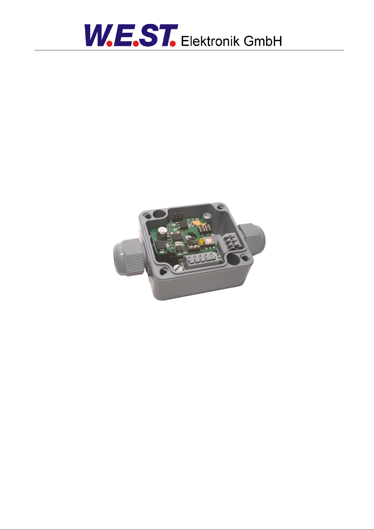
This power amplifier is used to control proportional valves with one solenoid. The compact solution is implemented in an inexpensive IP-65 housing.
A typical input signal of 0… 10 V (optional 4... 20 mA) can be used. The output current is closed loop con-
trolled and therefore independent from the supply voltage and a varying solenoid resistance.
The parameterization can be done via the PC interface and the ULA-310 adapter or internally via the UP and
DOWN buttons.
By the free parameterization of the power amplifier all typical proportional valves of the different manufactures
can be optimal adapted.
Typical applications: Controlling of the solenoid of proportional throttle or pressure valves.
Features
Power amplifier for proportional valves
Electronic board in a housing IP-65
Digital reproducible adjustments
Free scaling of the input signal
Reference output to supply potentiometers
Free parameterization of ramps, MIN and MAX, DITHER (frequency, amplitude) and
PWM frequency
Current range: 1 A, and 2,5 A
Simple and application orientated parameter settings
Failure monitoring and extended function check
Adjustments via LIN/USB interface, simplified parameterizing with WPC-300 software
Parameter settings via integrated buttons and a selector switch (reduced functionally against the
USB / LIN-bus)
Adaptable to all standard proportional valves
Page 6 of 24 PAM-190-P-*-1010 18.08.2015
Page 7
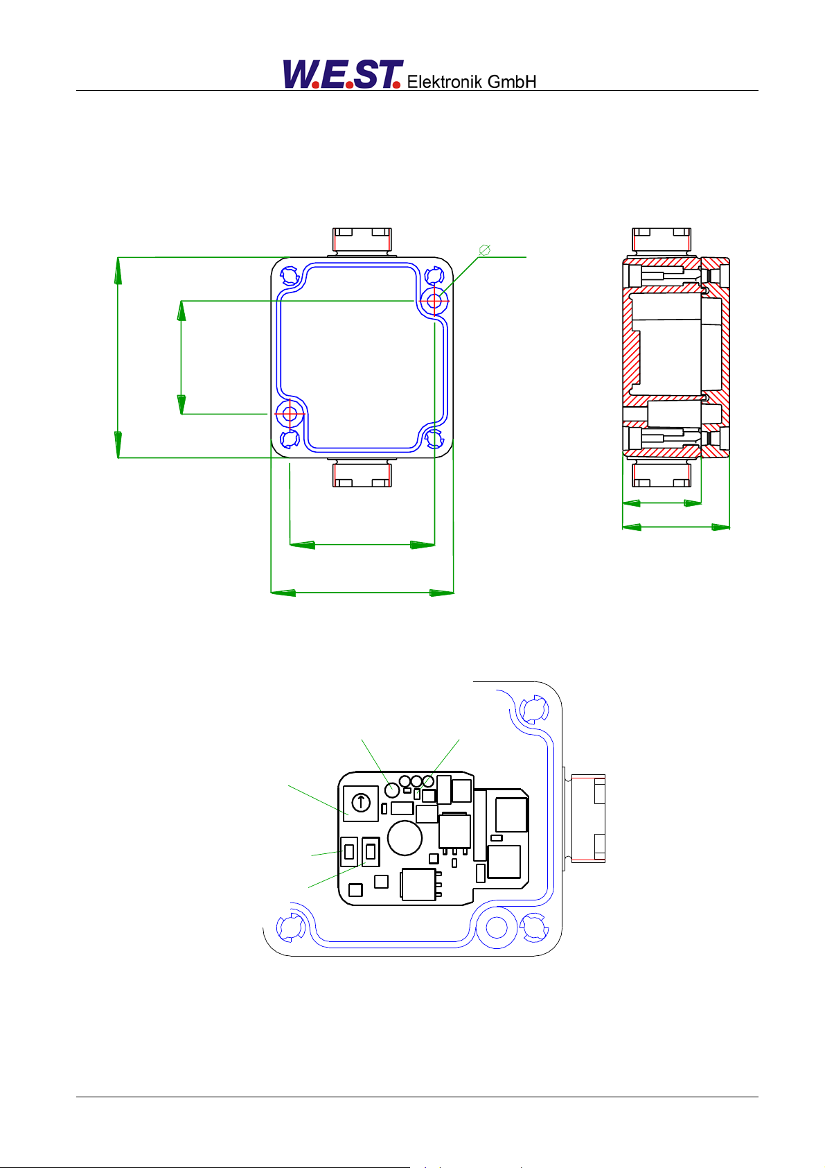
58 mm
4,5 mm
PG 11
64 mm
25 mm
34 mm
36 mm
46 mm
Selection
Switch/
Drehschalter
Button Down/
Taste Ab
Button Up/
Taste Auf
Operation LED/
Funktions LED
Parameter LED/
Parameter LED
1
2
3
4
5
6
7
8
9
0
2.1 Device description
Page 7 of 24 PAM-190-P-*-1010 18.08.2015
Page 8

3 Use and application
3.1 Installation instructions
All cables which lead outside must be screened; complete screening is required. It is also a require-
ment that no strong electro-magnetic interference sources are installed nearby when using our control
and regulation modules.
The equipment should be installed and wired in accordance with the documentation bearing in mind
EMC principles. If other consumers are operated with the same power supply, a star- connected
ground wiring scheme is recommended. The following points must be observed when wiring:
Analogue signal cables must be screened.
All other cables must be screened if there are powerful interference sources (frequency
converters, power contactors) and cable lengths > 3m. Inexpensive SMD ferrites can be
used with high-frequency radiation.
The screening should be connected to PE (PE terminal) as close to the equipment as pos-
sible. The local requirements for screening must be taken into account in all cases. The
screening should be connected to at both ends. Equipotential bonding must be provided
where there are differences between the connected electrical components.
With longer lengths of cable (>10 m) the diameters and screening measures should be
checked by specialists (e.g. for possible interference, noise sources and voltage drop).
Particular care is required with cables of over 40 m in length – the manufacturer should be
consulted if necessary.
A low-resistance connection between PE and the mounting rail should be provided. Transient interfer-
ence is transmitted from the equipment directly to the mounting rail and from there to the local earth.
Power should be supplied by a regulated power supply unit (typically a PELV system complying with
IEC364-4-4, secure low voltage). The low internal resistance of regulated power supplies gives better
interference voltage dissipation, which improves the signal quality of high-resolution sensors in particular. Switched inductances (relays and valve coils connected to the same power supply) must always
be provided with appropriate overvoltage protection directly at the coil.
Page 8 of 24 PAM-190-P-*-1010 18.08.2015
Page 9

Step
Task
Installation
Install the device in accordance with the circuit diagram. Ensure it is wired correctly and that the signals are well shielded.
Switching on for the first time
Ensure that no unwanted movement is possible in the drive (e.g. switch off the
hydraulics). Connect an ammeter and check the current consumed by the device. If it is higher than specified, there is an error in the wiring. Switch the device off immediately and check the wiring.
Setting up communication
Once the power input is correct the PC (notebook) should be connected via the
USB interface and the programming device ULA-310. Please see the WPC300 program documentation for how to set up communication.
Caution:
The communication works in a HALF DUPLEX process.
Further commissioning and diagnosis are supported by the operating software.
Alternatively, the set-up can be done by the internal parameter selector and the
UP and DOWN buttons.
Pre-parameterization
Parameterize now (with the help of the system redundancy and the connection
diagram) the following parameters:
The ANALOGUE INPUT, the output CURRENT and the typical valve parameter DITHER and MIN/MAX.
Pre-parameterization is necessary to minimize the risk of an unintentional
movement / pressure.
Control signal
Check the control signal (output signal). The control signal (solenoid current)
lies in the range of 0... 2.5 A. In the current state it should show around 0 A.
The valve current can also be monitored in the WPC program.
Switching on the hydraulics
The hydraulics can now be switched on. The module is not yet generating a
signal. Drives should be at a standstill or drift slightly (leave its position at a
slow speed).
Activating command signal
CAUTION! The power stage is always active when power supply exists. The
output current to the valve will follow the input signal proportionally.
Controller optimization
Settings like ramp time or dead band compensation can now be done.
3.2 Commissioning
Page 9 of 24 PAM-190-P-*-1010 18.08.2015
Page 10

Switch
position
Parameter
Setting range
Remark
0
DEFAULT
-
Released only by pressing the button "Up" and "DOWN"
simultaneously. Response: a short and fast flashing of
the LED.
1
CURRENT
0 | 1
0 = low current range; press button “DOWN“
1 = high current range; press button “UP“
2
MIN
0…60%
Deadband compensation
in relation to the current range
3
MAX
30…100%
Reduction in the maximum current
in relation to the current range
4
R:UP
50ms…5sec
Ramp time up
5
R:DOWN
50ms…5sec
Ramp time down
6
PWM
60…1500 Hz
PWM output frequency
7 -
No function
8 -
No function
9 -
No function
2
3.3 Manual parameterization
3.3.1 Parameter overview
The manual adjustment is comparable with the adjustment via potentiometer. Not all parameter of the power
plug are available in this mode2.
3.3.2 Procedural method
1. Press a button or turn the selector switch which activates the manual adjustment mode. The parameter-LED flashes.
2. Select the desired parameter (1… 6) by the selector switch.
3. The parameter LED indicates - by flashing - the parameter mode.
a. At the lower boundary the LED lights only briefly
b. At the upper boundary the LED lights almost continuously
4. Press the UP or DOWN button.
a. A short activation of one of the buttons will change the parameter by a value of app. 1%.
b. A continual activation of one of the buttons will change the parameter continually (up to the
point where the upper or lower boundary is reached).
5. The parameters are stored automatically (app. 1 second after the last parameter adjustment). The
manual adjustment will be finished after 60 seconds.
The full functionality of the power plug is available via the PC interface only.
Page 10 of 24 PAM-190-P-*-1010 18.08.2015
Page 11

LEDs
Description of the LED function
FUNCTION LED
(yellow THD)
OFF: no power supply
ON: System is ready for operation
Flashing: Error detected:
PARAMETER LED
(yellow SMD)
Active in manual mode only.
Terminal
Analogue inputs and outputs
K3 PIN 2
External command value, range of 0… 10 V or 4… 20 mA, scalable
K3 PIN 3
Reference voltage 8V / 10 mA.
Terminal
Power supply
K3 PIN 5
K1 PIN 3
Power supply (see technical data)
K3 PIN 4
0V (GND)
Terminal
Solenoid
K2 PIN 2 / PIN 3
PWM output for solenoid control.
K2 PIN 1
PE
Terminal
Communication interface
K1 PIN 2
K3 PIN 1
LIN-bus connection (to ULA-310)
K1 PIN 1
GND
4 Technical description
4.1 Input and output signals
4.2 LED definitions
Page 11 of 24 PAM-190-P-*-1010 18.08.2015
Page 12
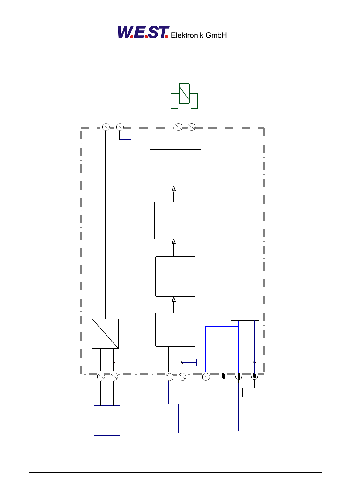
K3.5
K3.4
K3.2
K3.4
K1.2
Commands:
AIN:W
LIM
Input Scaling /
Skalierung
PAM-140-P
A: 0...10V
0 V
Output Adaptation
/ Ventiladaption
w
u
Control program
RAMP Generator /
Rampengenerator
Commands:
R:UP, R:DOWN
Input / Eingang
Commands:
- MIN
- MAX
- TRIGGER
- POL
DC
DC
24 V
0 V
PELV
c
Commands:
- LG (Languages)
- MODE (Expert or Standard)
Power Stage /
Ausgangsstufe
Commands:
- CURRENT
- DFREQ
- DAMPL
- PWM
- PPWM
- IPWM
ia
Solenoid / Magnet
Differential input /
Differenzeingang
LIN Bus
Communication
Kommunikation
Reference Voltage
Referenzspannung
K1.1
K2.2
K2.3
K3.3
K3.4
K1.3
UB
UB
K3.1
4.3 Circuit diagram
Page 12 of 24 PAM-190-P-*-1010 18.08.2015
Page 13
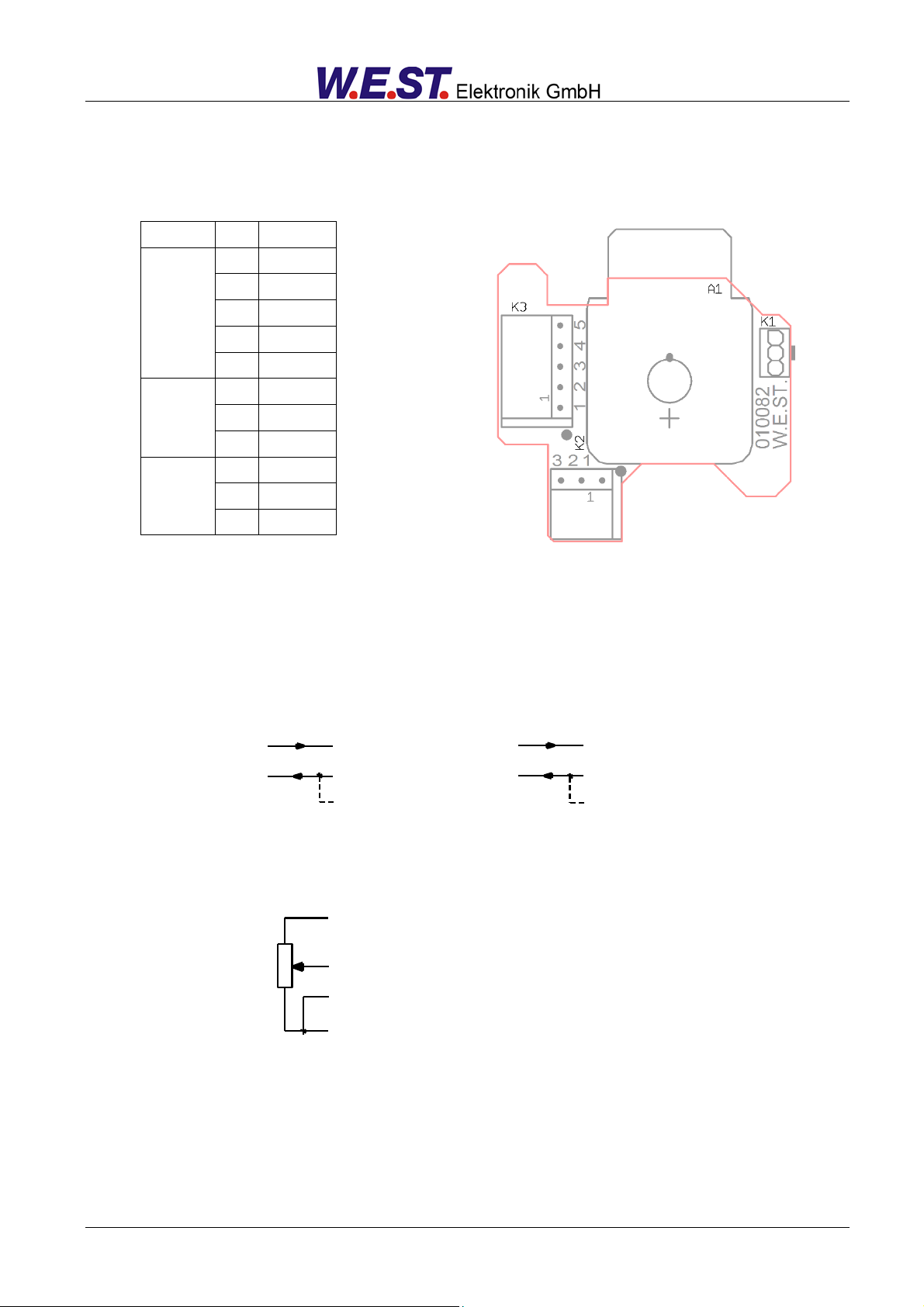
8V
GND
+In
-In
Potentiometer
+In PIN 2
-In PIN 4
PLC 0... 10 V 4... 20 mA input
+In PIN 2
-In PIN 4
GND PIN 3
AIN:W 2000 1600 2000 C (for 0... 100%)
AIN:W 1000 800 0 V (for 0... 100%)
GND
Terminal
Pin
Function
K3
1
LIN
2
AIN +
3
REF
4
GND
5
UB
K2
1
PE
2
Solenoid
3
Solenoid
K1
1
GND
2
LIN 3 UB
4.4 Typical wiring
4.5 Connection examples
Page 13 of 24 PAM-190-P-*-1010 18.08.2015
Page 14

Supply voltage
Current requirement
External protection
[VDC]
[mA]
[A]
12… 30 (incl. ripple)
< 50 + solenoid current
3 medium time lag
Analogue command input
Resolution
[V]
[mA]
[%]
0… 10; 90 kOhm
4...20; 240 Ohm
< 0,1 (intern 0,02) incl. oversampling
Reference voltage
[V]
8 (max. 10 mA)
PWM output
PWM frequency
[A]
[Hz]
Max. 1 or 2.5 (selectable)
60… 2650 adjustable stepwise
Sample time (pressure control)
Sample time (solenoid current control)
[ms]
[ms]
1
0,167
Serial interface
Baudrate [kB]
LIN-bus
19,2
Housing
Dimensions
[mm]
PA 6-GB 30, Seal: CR
98 x 64 x 34
Weight
[kg]
0,110
Protection class
Temperature range
Storage temperature
[°C]
[°C]
IP 65/DIN EN 60529
-20… 60
-20… 70
Connections
Cable-cross section
[mm²]
Push-in CAGE CLAMP
0.2… 1.5 / 24… 16 AWG
EMC
EN 61000-6-2: 8/2002
EN 61000-6-3: 6/2005
4.6 Technical data
Page 14 of 24 PAM-190-P-*-1010 18.08.2015
Page 15

Group
Command
Default
Unit
Description
Basic parameters
LG
EN
-
Changing language help texts
MODE
STD
-
Parameter view
Input signal adaptation
Signal scaling
AIN:W
A: 1000
B: 1000
C: 0
X: V
-
-
0,01 %
-
Free scaling of the analogue input.
Range monitoring
LIM
0
0,01 %
Signal monitoring function (e.g. joystick error)
Ramp function
R:UP
R:DOWN
100
100
ms
ms
Command signal ramp times
Output signal adaptation
MIN
0
0,01 %
Deadband compensation
MAX
10000
0,01 %
Output scaling
TRIGGER
200
0,01 %
Deadband compensation trigger point
POL
+
-
Output polarity
Powerstage parameters
CURRENT
0
-
Current output range
DFREQ
120
Hz
Dither frequency
DAMPL
0
0,01 %
Dither amplitude
PWM
488
Hz
PWM frequency
PPWM
IPWM
1
40
-
-
Gain of the current loop
5 Parameters
5.1 Parameter overview
Page 15 of 24 PAM-190-P-*-1010 18.08.2015
Page 16

Command
Parameters
Unit
Group
LG x
x= DE|EN
-
STD
Command
Parameters
Unit
Group
MODE x
x= STD|EXP
-
STD
5.2 Basic parameters
5.2.1 LG (Changing the language)
Either German or English can be selected for the help texts.
CAUTION: After changing the language settings, the parameter list has to be updated by pressing the
identification button “ID”.
5.2.2 MODE (Parameter view)
This command changes the operating mode. Various commands (defined via STD/EXP) are blanked out in
Standard Mode. The commands in Expert Mode have a more significant influence on system behavior and
should accordingly be changed with care.
Page 16 of 24 PAM-190-P-*-1010 18.08.2015
Page 17

Command
Parameters
Unit
Group
AIN:W
A
B
C
X
a= -10000… 10000
b= -10000… 10000
c= -10000… 10000
x= V|C
-
-
0,01 %
-
STD
)( cInput
b
a
Output
Command
Input
Description
AIN:X 1000 1000 0 V
0… 10 V
Range: 0… 100 %
AIN:X 10 8 1000 V OR
AIN:X 1250 1000 1000 V
1… 9 V
Range: 0… 100 %; 1 V = 1000 used for the offset and
gained by 10 / 8 (10 V divided by 8 V (9 V -1 V))
AIN:X 10 4 500 V OR
AIN:X 2500 1000 500 V OR
0,5… 4,5 V
Range: 0… 100 %; 0,5 V = 500 used for the offset and
gained by 10 / 4 (10 V divided by 4 V (4,5 V -0,5 V))
AIN:X 20 16 2000 C OR
AIN:X 2000 1600 2000 C OR
AIN:X 1250 1000 2000 C
4… 20mA
Range: 0… 100 %
The offset will be compensated on 20 % (4 mA) and the
signal (16 mA = 20 mA – 4 mA) will be gained to 100 %
(20 mA).
Each of this parameterization for 4… 20 mA is setting the
range to 0… 100 %.
5.3 Input signal adaptation
5.3.1 AIN (Analogue input scaling)
This command offers an individual scalable input. The following linear equation is used for the scaling.
The “C” value is the offset (e.g. to compensate the 4 mA in case of a 4… 20 mA input signal).
The variables A and B are defining the gain factor with which the signal range is scaled up to 100 % (e.g. 1.25
if using 4… 20mA input signal, defined in default current settings by A = 1250 and B = 1000). The internal
shunt for the current measuring is activated with switching the X value.
The gain factor is calculated by setting the usable range (A) in relation to the real used range (B) of the input
signal. Usable are 0… 20mA, means (A) has the value 20. Really used are 4… 20mA, means (B) has a value
of 16 (20-4). Not used are 0… 4mA. In a range of 20mA this is an offset of 20%, means a value of 2000 for
(C). Last but not least (X) has to be set to C choosing current signal.
In this case AIN command would look like this:
AIN:I 20 16 2000 C or AIN:I 1250 1000 2000 C (see below)
Typical settings:
Page 17 of 24 PAM-190-P-*-1010 18.08.2015
Page 18

Command
Parameters
Unit
Group
LIM X
x= 0… 2000
0,01 %
EXP
Command
Parameter
Unit
Group
R:I X
i= UP|DOWN
x= 50… 10000
ms
STD
t
Ausgang/Output A
A:UP
A:DOWN
0%
working
range
error range for
unipolar signals
100%
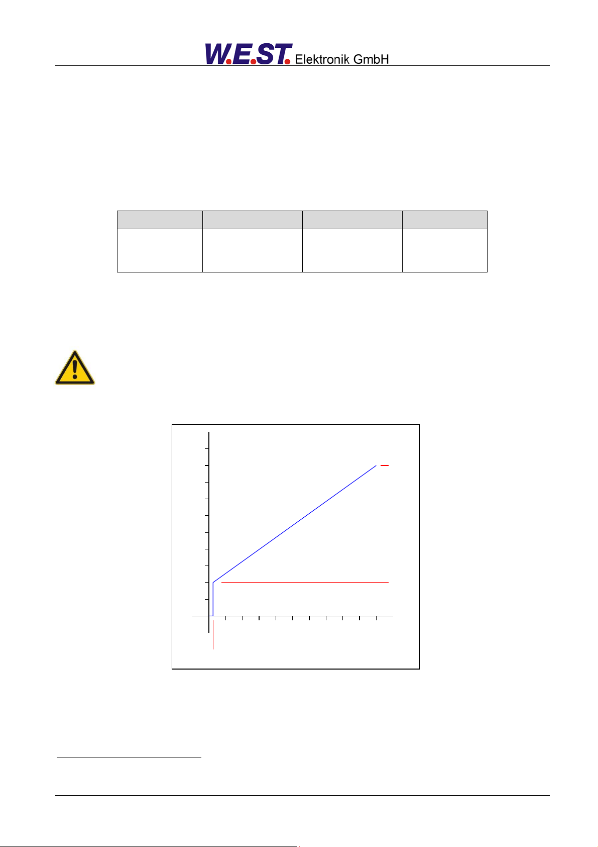
5.3.2 LIM (Signal monitoring)
This command defines the pressure, which corresponds to 100 % of the input signal. If the demand is set
incorrectly, this leads to incorrect system settings, and the dependent parameters cannot be calculated
correctly.
Example: LIM 500 (5% lower/upper limitation)
If the input signal gets higher than 95 % or lower than 5%, it leaves the permitted range and the output will
switch off.
5.3.3 R (Command signal ramp time)
Two quadrant ramp function.
The ramp time is separately set for UP and DOWN ramps.
Page 18 of 24 PAM-190-P-*-1010 18.08.2015
Page 19
Command
Parameters
Unit
Group
MIN X
MAX X
TRIGGER X
x= 0… 6000
x= 2000… 10000
x= 0… 3000
0,01 %
0,01 %
0,01 %
STD
3
Eingang / Input
100%
10V
Ausgang / Output
MAX
MIN
TRIGGER
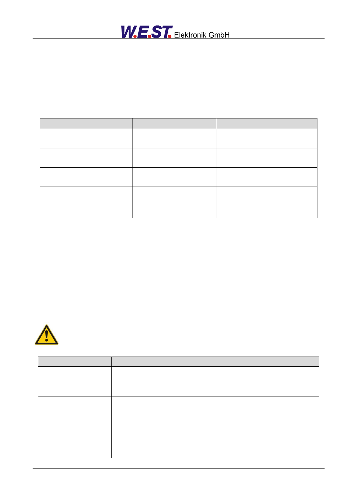
5.4 Output signal adaptation
5.4.1 MIN (Deadband compensation)
5.4.2 MAX (Output scaling)
5.4.3 TRIGGER (Response threshold for the MIN parameter)
With this command, the output signal is adjusted to the valve characteristics. With the MAX value the output
signal (the maximum valve current) will be defined. With the MIN value the overlap (dead band of the valve)
will be compensated. Via the TRIGGER the activation point of the MIN function is set and so a non-sensitive
range around the zero-point3 can be specified.
CAUTION: If the MIN value is set too high, it influences the minimal pressure, which cannot be adjusted any longer. In extreme case this causes to an oscillating at small input values.
This dead band is necessary, in order to avoid unrequested activations caused by small variations of the input signal. If
this module is used in a position controls, the TRIGGER value should be reduced (typical: 1…10).
Page 19 of 24 PAM-190-P-*-1010 18.08.2015
Page 20

Command
Parameter
Unit
Group
POL X
x= + | -
-
EXP
Command
Parameters
Unit
Group
CURRENT X
x= 0|1
-
STD
Command
Parameters
Unit
Group
DFREQ X
DAMPL X
x= 60… 400
x= 0… 3000
Hz
0,01 %
EXP
4
5.4.4 POL (Output polarity)
This command allows a switch over of the output signal direction (after the MIN-MAX function).
Example: POL:A + Input signal 0… 100 %, nominal output current 0… 100 %.
POL:A - Input signal 0… 100 % nominal output current 100… 0 %.
5.5 Output signal adaptation
5.5.1 CURRENT (Rated current range)
The nominal current range is set with this parameter. Dither and also MIN/MAX always refer to the selected
current range.
0 = 1.0 A range
1 = 2.5 A range
5.5.2 DFREQ (Dither frequency)
5.5.3 DAMPL (Dither amplitude)
The dither4 can be defined freely with this command. Different amplitudes or frequencies may be required depending on the respective valve. The dither amplitude is defined in % of the nominal current (see: CURRENT
command).
CAUTION: The PPWM and IPWM parameters influence the effect of the dither setting. These parameters should not be changed again after the dither has been optimized.
CAUTION: If the PWM frequency is less than 500 Hz, the dither amplitude should be set to zero.
The DITHER is a superimposed signal to reduce the hysteresis. This function is defined by the amplitude and frequency.
The DITHER frequency should not be confused with the PWM frequency. In some proportional valve documentations a
mistake is done by the definition of the DITHER / PWM frequency. It is recognizable by missing information about the
DITHER amplitude.
Page 20 of 24 PAM-190-P-*-1010 18.08.2015
Page 21

Command
Parameter
Unit
Group
PWM X
x= 60… 2650
Hz
STD
Command
Parameters
Unit
Group
PPWM X
IPWM X
x= 0… 30
x= 1… 100
-
-
EXP
5
5.5.4 PWM (PWM Frequency)
This parameter is entered in Hz. The optimum frequency depends on the valve.
CAUTION: when using low PWM frequencies the PPWM and PPWM parameters should be
adjusted5.
The PWM frequency can only be set in defined steps. This means that there are deviations between
the specified and the actual frequency. The next highest frequency step is always used.
5.5.5 PPWM (P gain of the current loop)
5.5.6 IPWM (I gain of the current loop)
The PI current controller for the solenoids is parameterized with these commands.
CAUTION: These parameters should not be changed without adequate measurement facilities
and experience.
If the PWM frequency is < 250 Hz, the dynamic of the current controller has to be decreased.
Typical values are: PPWM = 1… 3 and IPWM = 40… 80.
If the PWM frequency is > 1000 Hz, the default values of PPWM = 7 and IPWM = 40 should be chosen.
Due to the longer dead times at low PWM frequencies the stability of the control circuit is reduced. Typical values are
then: PPWM = 1… 3 and IPWM = 40… 70.
Page 21 of 24 PAM-190-P-*-1010 18.08.2015
Page 22

Command
Description
Unit
W
C
U
IA
Command value after input scaling
Comman value after ramp function
Control signal
Solenoid current6
%
%
%
mA
6
5.6 PROCESS DATA (Monitoring)
The process data are the variables which can be observed continuously on the monitor or on the oscilloscope.
The display of the solenoid current (in WPC-300 program) is damped in order to be able to bring out a stable signal.
Page 22 of 24 PAM-190-P-*-1010 18.08.2015
Page 23
Source
Fault
Characteristic
Command signal LIM command
K3 PIN 2 / 4
Out of range
The output will be switched off and
the READY LED flashes.
Command signal 4… 20 mA
K3 PIN 2 / 4
Out of range or broken wire
The output will be switched off and
the READY LED flashes.
Solenoids output
K2 PIN 2 / 3
Wrong cabling, broken wire
The output will be switched off and
the READY LED flashes.
EEPROM
(when switching on)
Data error
The output will be switched off and
the READY LED flashes.The module can only be activated by saving
the parameters again!
FAULT
CAUSE / SOLUTION
READY LED is off.
Presumably no power supply is present.
If there is no power supply there is also no communication via our operating pro-
gram. If a connection has been made to the WPC-300, then a power supply is also
available.
READY LED is flashing.
The flashing READY LED signals that a fault is detected by the equipment. The fault
could be:
Solenoid error or no signal at the input, if 4… 20 mA signals
LIM monitored input signals are parameterized.
Internal data error: press the command/SAVE button to delete the data error. The
system reloads the DEFAULT data.
With the WPC-300 operating program and ULA-310 the fault can be localized directly
via the monitor.
6 Appendix
6.1 Failure monitoring
Following possible error sources are monitored continuously:
6.2 Troubleshooting
It is assumed that the device is in an operable state and there is communication between the module and the
WPC-300. Furthermore, the valve control parameterization has been set with the assistance of the valve data
sheets.
The RC in monitor mode can be used to analyze faults.
CAUTION: All safety aspects must be thoroughly checked when working with the RC (Remote
Control) mode. In this mode the module is controlled directly and the machine control cannot
influence the module.
Page 23 of 24 PAM-190-P-*-1010 18.08.2015
Page 24

7 Notes
Page 24 of 24 PAM-190-P-*-1010 18.08.2015
 Loading...