

Page 1
PMA Prozeß- und Maschinen-Automation GmbH
1
Temperature limiterTB 40-1
TB40-1
TB40-
Operating manual
English
9499-040-93411
Valid from: 8505
Page 2

û
ATTENTION!
Mini Version and Updates on
or on PMA-CD
www.pma-online.de
BlueControl
More efficiency in engineering,
more overview in operating:
The projecting environment for the BluePort
®
controllers
Description of symbols
in the text: on the device:
g General information a Follow the operating instructions
a General warning
l Attention: ESD-sensitive devices
© PMA Prozeß- und Maschinen-Automation GmbH • Printed in Germany
All rights reserved. No part of this document may be reproduced or published in any form or by
any means without prior written permission from the copyright owner.
A publication of PMA Prozeß- und Maschinen Automation
P.O.Box 310229
D-34058 Kassel
Germany
Page 3
Contents
1 Mounting .............................. 4
2 Electrical connections ....................... 5
2.1 Connecting diagram TB 40-1 temperature limiter TB .......5
2.1.1 Terminal connection ...........................5
2.2 Connecting diagram TB 40-1 temperature monitor TW ......7
3 Operation.............................. 8
3.1 Front view.............................. 8
3.2 Behaviour after power-on ...................... 8
3.3 Behavior with sensor break/ measuring circuit error ........9
3.4 Setting of the limit value LC / Extended operating level ......9
3.5 Maintenance manager / Error list .................10
3.6 Alarm handling .......................... 11
3.6.1 Alarm handling limit value LC .....................11
3.6.2 Alarm handling additional alarms ....................12
3.7 Operating structure ........................ 13
4 Configuration level ........................14
4.1 Configuration survey .......................14
4.2 Configuration ........................... 15
5 Parameter setting level ...................... 18
5.1 Parameter survey ......................... 18
5.2 Parameters ............................. 18
5.3 Input scaling InP.1........................ 19
6 Calibration level ......................... 20
7 BlueControl ............................ 23
8 Versions .............................. 24
9 Technical data .......................... 25
10 Safety hints ............................ 28
10.1 Resetting to factory setting .................... 30
TB40-1 3
Page 4
Mounting
°C
Err
°F
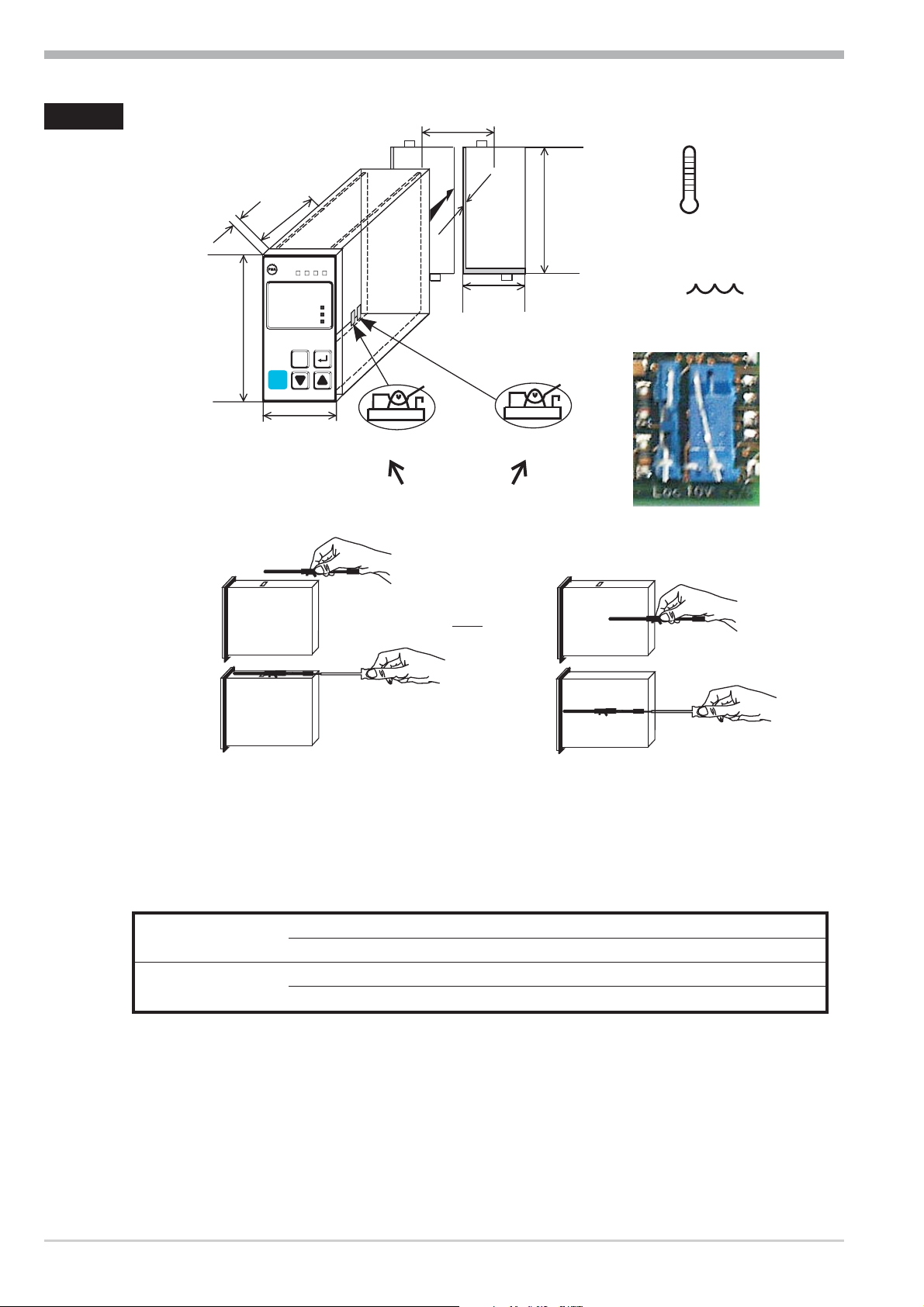
1 Mounting
(0.4")
10
118
(3.78")
96
TB 40-1 universal
48 (1.89")
(4.65")
2LC
OK
1
126
125
RESET
min.48
(1.89")
1..10
(0.04..0.4")
+0,6
45
+0.02
(1.77" )
Loc
10V i mA/Pt
Safety switches
+0,8
+0.03
92
max.
(3.62" )
max.
95% rel.
Loc 10V mA/Pt
60°C
0°Cmin.
%
Loc 10V mA/Pt
Loc 10V mA/Pt
Ü
or:
Ü
*
*
Safety switch:
For access to the safety switches, the controller must be withdrawn from the hou
sing. Squeeze the top and bottom of the front bezel between thumb and forefinger
and pull the temperature limiter firmly from the housing.
1 Factory setting
10V i mA/Pt right 1 Current signal / Pt100 / thermocouple at InP.1
left Voltage signal at InP.1
Loc open Access to all levels locked
closed
1 all levels accessible via password PASS
-
a
l
Safety switch 10V i mA/Pt always in position left or right. Leaving the
safety switch open may lead to faulty functions!
Caution! The unit contains ESD-sensitive components.
4 TB40-1
Page 5
Electrical connections
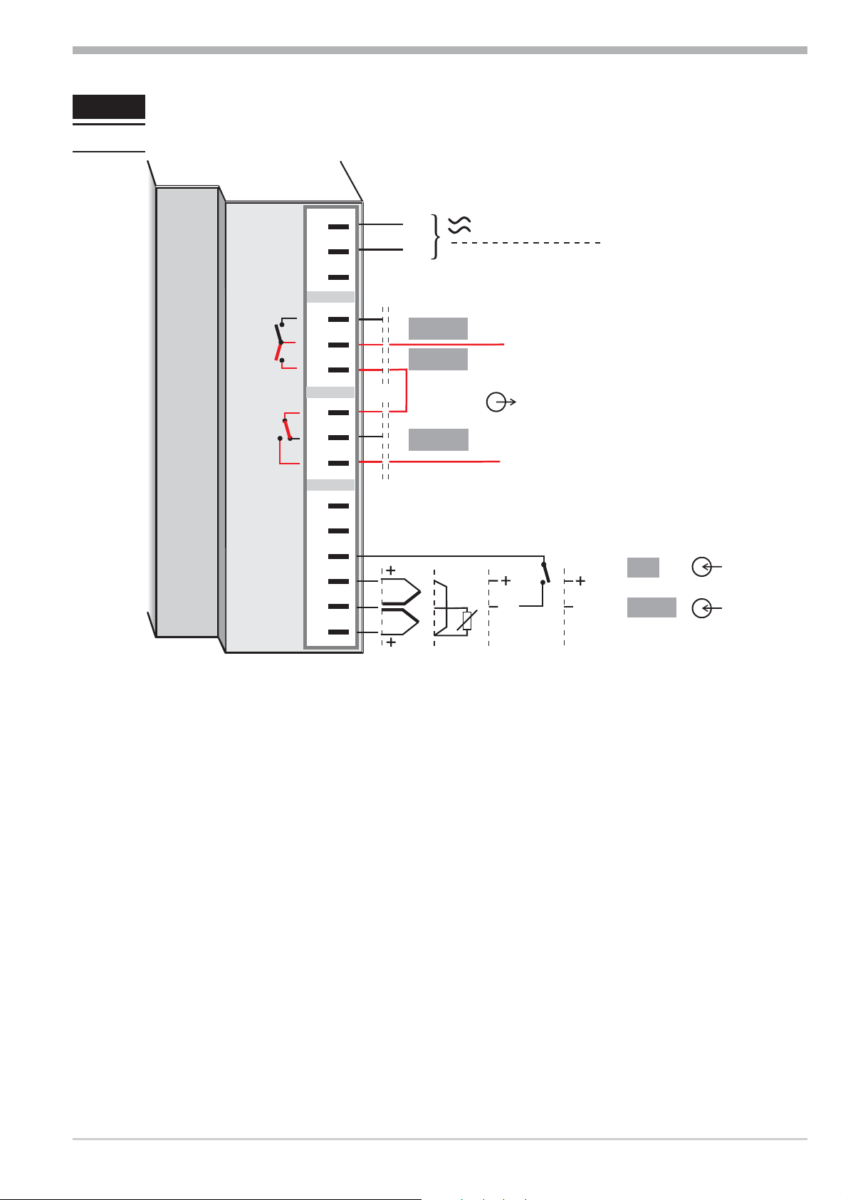
2 Electrical connections
2.1 Connecting diagram TB 40-1 temperature limiter TB
10
11
12
13
14
15
1
2
L
N
90...250V
24V AC/DC
3
4
OUT1
5
6
7
8
9
OUT2
LC
Zusatzkontakt /
Additional contact
Abschaltfunktion
Interrupt function
mA
V*
di1
INP1
* Safety switch mA i V in position left
g
The controller is fitted with
- flat-pin terminals 1 x 6,3mm or 2 x 2,8mm according to DIN 46 244 or
- screw terminals from 0,5 to 2,5mm².
2.1.1 Terminal connection
Power supply connection 1
See chapter "Technical data"
Connection of input INP1 2
Input for variable x1 (process value)
a thermocouple
b resistance thermometer (Pt100/ Pt1000/ KTY/ ...)
c current (0/4...20mA)
d voltage (0/2...10V)
Connection of input di1 3
Digital input, configurable as switch or push-button
TB40-1 5 Connecting diagram TB 40-1 temperature limiter TB
Page 6
Electrical connections
+
_
Connection of output OUT LC 4
Relay (250V/2A), potential-free changeover contact
Connection of outputs OUT1/2 5
Relay outputs 250V/2A normally open with common contact connection
L1
L2
a
a
KS 40-1
The pre-alarms (OUT1/2) must be used only for signalling and not for control
purposes!
The pre-alarm OUT2 is available only if configured as TW!
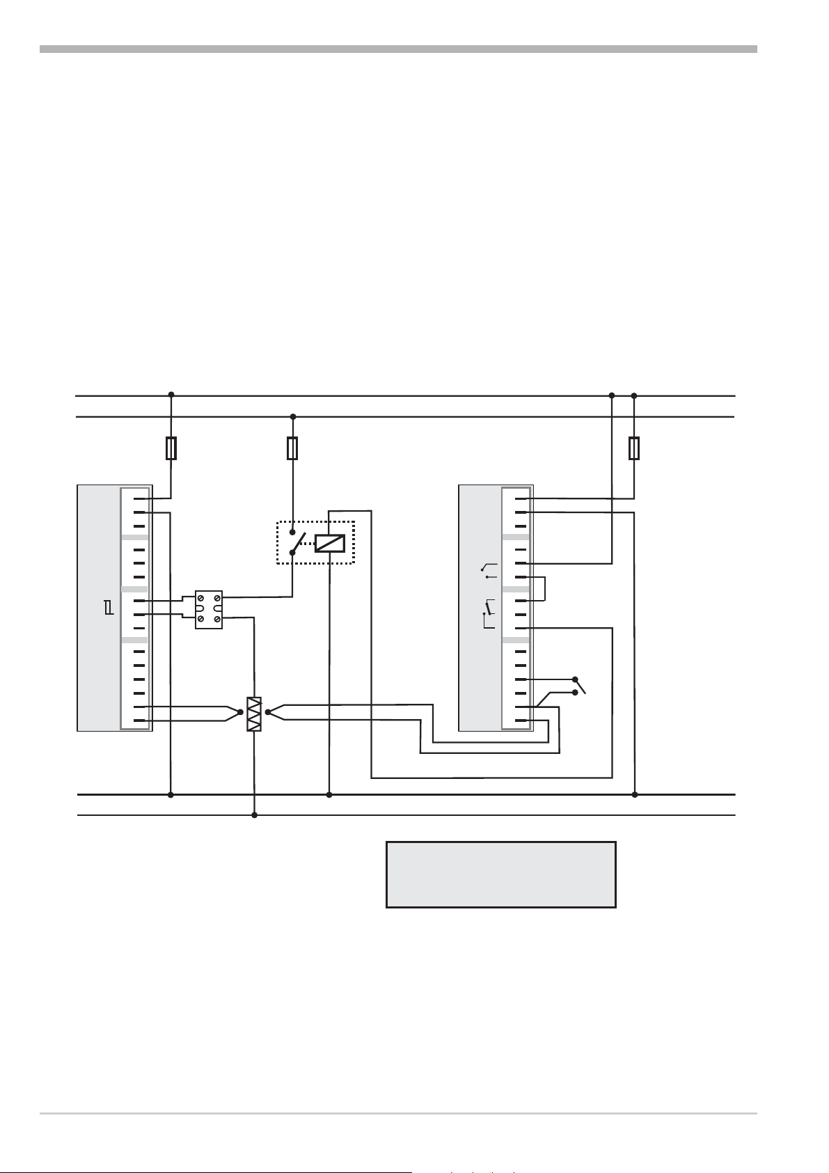
TB40-1 connecting example:
Logic
fuse
1
2
3
4
5
6
7
8
9
SSR
fuse
contactor
TB 40-1
Temperature limiter
1
1
2
3
4
5
6
7
8
9
fuse
N1
N2
a
10
11
12
13
14
15
+
heating
1 TB 40-1 Temperature limiter
Standard version (2 relays):
TB40-102-0000D-000
other versions on requestr
10
11
12
13
14
15
reset
+
CAUTION:
Using a temperature limiter is recommendable in systems where overtemperature
implies a fire hazard or other risks.
Connecting diagram TB 40-1 temperature limiter TB 6 TB40-1
Page 7
Electrical connections
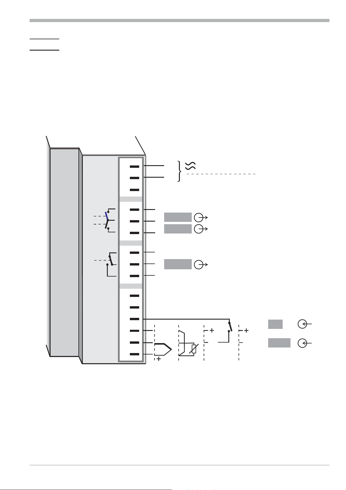
2.2 Connecting diagram TB 40-1 temperature monitor TW
The TB 40-1 temperature limiter can also be configured as temperature moni
tor. The connection of the 2nd thermocouple is omitted (terminals 12 –13).
Relay contacts OUT1 and OUT2 can be configured as additional limit outputs
and connected according to the connecting diagram below.
Limit contact LC also is also connected according to the connecting diagram be
low.
1
2
L
N
90...250V
24V AC/DC
3
4
5
6
OUT1
OUT2
Zusatzkontakte /
Additional contacts
-
-
7
8
9
10
11
12
13
14
15
LC
Limit contact
mA
di1
V*
INP1
TB40-1 7 Connecting diagram TB 40-1 temperature monitor TW
Page 8
Operation
TB 40-1 universal
125
126.
°C
Err
°F
1 2 LC OK
3
1
2
3
4
5
6
9
7
8
0
!
"
RESET
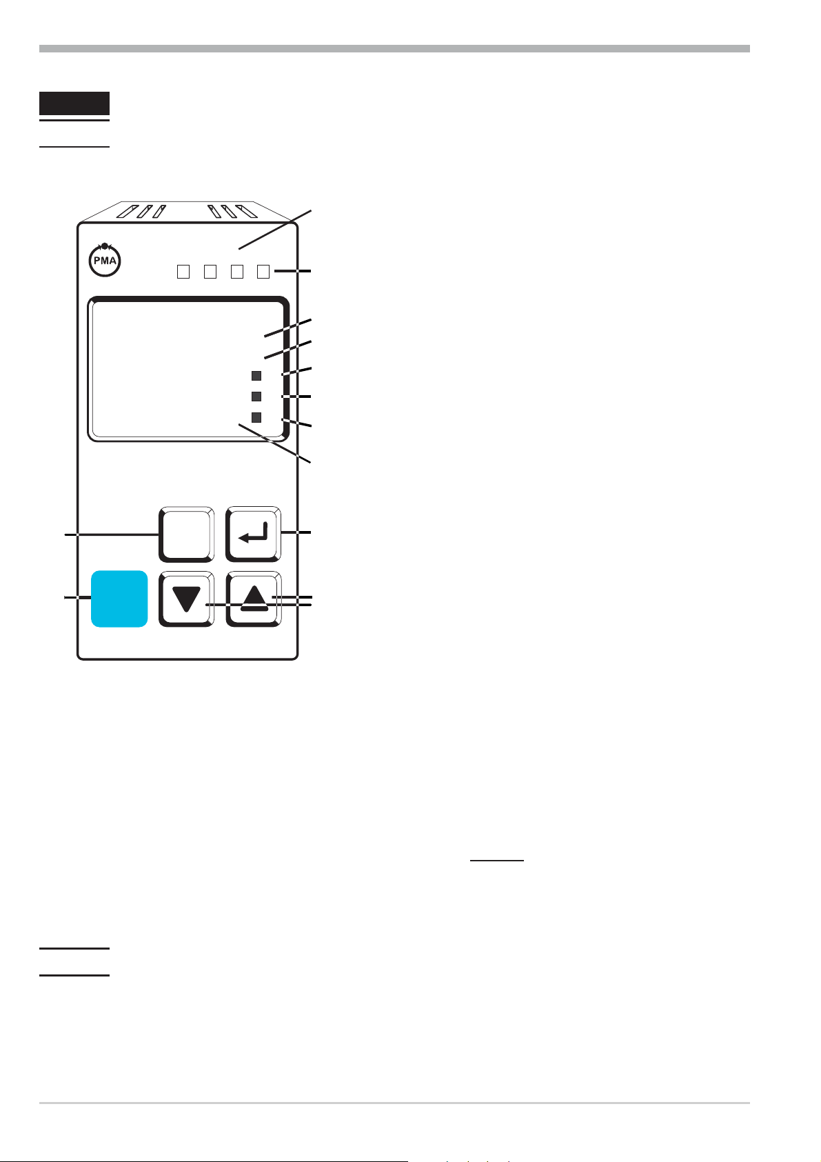
3 Operation
3.1 Front view
1 Status of limits
Lim.2, Lim.3, LC
2 Lit with limit value 1
( PArA / Lim ) not exceeded
3 Process value display
4 Set-point LC
5 Signals ConF and PArA level
6 Display in degrees celsius (°C)
7 Display in degrees farenheit (°F)
8 Entry in error list
9 Enter key:
calls up extended operating
level / error list
0 Up/down keys:
changing the set-point or the
controller output value
! RESET key for reset of
latched errors
" PC connection for BlueControl
(engineering tool)
LED colours:
LED 1, 2, 3: yellow
LED OK: green
other LEDs: red
g
In the upper display line, the process value is always displayed (Exception:
ConF / othr/ disp = 0). At parameter, configuration, calibration as well as
extended operating level, the bottom display line changes cyclically between
parameter name and parameter value.
3.2 Behaviour after power-on
After supply voltage switch-on, the unit starts with the operating level.
The unit is in the condition which was active before power-off.
Front view 8 TB40-1
Page 9
Operation
3.3 Behavior with sensor break/ measuring circuit error
If a sensor break/ measuring circuit error is recognized, the process value display
changes to FAIL and the Err-LED blinks. ( -> Page 11 chapter 3.5 maintenance
manager/ error list). All configured alarm limts are handled as exceeded, the ap
propriate Outputs are switched. The OK-LED ceases and the LC Output is ope
ned.
3.4 Setting of the limit value LC / Extended operating level
-
-
Setting of the limit value LC
126
125
3s.
Ù
PArA
Ù
Display
PASS
Ù
Ù
changes
Lim
All levels only
accessible if
p
safety switch
is closed!
45
Set to 45
È
Ì
Loc
Extended operating level
126
125
Ù
Errorlist (if error exists)
switching
Err
display
126
Lim.1
Extended operatinglevel
126
2
Err
LC
Ù
.
.
.
.
InP.1
Ì
.
.
.
.
EnD
Ù
Display
changes
or 5 s.
125
Freely
adjustable!
È
Ì
TB40-1 9 Behavior with sensor break/ measuring circuit error
Page 10

Operation
3.5 Maintenance manager / Error list
With one or several errors, the extended operating level al
ways starts with the error list. Signalling an actual entry in
-
126
the error list (alarm, error) is done by the Err LED in the
display. To reach the error list press Ù twice.
Err LED status Signification Proceed as follows
blinks Alarm due to existing error
lit Error removed,
Alarm not acknowledged
off No error,
all alarm entries deleted
Determine the error type in the error list
via the error number
Remove the error
Acknowledge the alarm in the error list
pressing key È or Ì
The alarm entry was deleted.
-
125
Error list:
°C
°F
Err
Name
E.1
E.2
FbF.1
Sht.1
POL.1
Lim.1
Lim.2
Lim.3
Inf.1
Description Cause Possible remedial action
Internal error,
cannot be removed
Internal error, can be
reset
Sensor break INP1
Short circuit INP1
INP1polarity error
Stored LC alarm
Stored alarm 2
Stored alarm 3
time limit value
message
- E.g. defective EEPROM - Contact PMA service
- Return unit to our factory
- e.g. EMC trouble - Keep measurement and power
supply cables in separate runs
-
Ensure that interference
suppression of contactors is
provided
-
Sensor defective
-
Faulty cabling
-
Sensor defective
-
Faulty cabling
-
Faulty cabling
-
adjusted limit value LC
exceeded
-
adjusted limit value
alarm 2 exceeded
-
adjusted limit value
alarm 3 exceeded
-
adjusted number of
operating hours reached
-
Replace INP1 sensor
-
Check INP1 connection
-
Replace INP1 sensor
-
Check INP1 connection
-
Reverse INP1 polarity
-
check process
-
check process
-
check process
-
application-specific
Maintenance manager / Error list 10 TB40-1
Page 11

Operation
g
Saved alarms (Err-LED is lit) can be acknowledged and deleted with the digital
input di1 or the RESET-key.
Configuration, see page : ConF / LOGI / Err.r
g
If an alarm is still valid that means the cause of the alarm is not removed so far
(Err-LED blinks), then other saved alarms can not be acknowledged and deleted.
Error status:
Error status Signification
2 Existing error Change to error status 1 after error removal
1 Stored error Change to error status 0 after acknowledgement in error list
0 No error/message not visible, except with acknowledgement
3.6 Alarm handling
3.6.1 Alarm handling limit value LC
Method of operation upper limit:
( ConF / Lim / Fcn.1 = 3 )
Method of operation lower limit:
( ConF / Lim / Fcn.1 = 4 )
InL.1
InL.1
OK - LED
green
LC - LED
yellow
SEtP
0,5 K
SEtP
0,5 K
InH.1
LC - LED
yellow
InH.1
OK - LED
green
TB40-1 11 Alarm handling
Page 12

Operation
3.6.2 Alarm handling additional alarms
Max. two alarms can be configured and assigned to the individual outputs. Gene
rally, outputs OuT.1and OuT.2 can be used each for alarm signalling. Each of
the 2 limit values Lim.2 and Lim.3 has 2 trigger points H.2/ H.3 (Max) and
L.2 / L.3 (Min), which can be switched off individually (parameter = “OFF”).
Switching difference HYS.2/ HYS.3 of each limit value is adjustable.
Ü Operaing principle Src.x = 0
L.1 = OFF
InL.1
H.2
HYS.2
LED
1
2
H.1 = OFF
InH.1
* Operaing principle Src.x = 1
L.1 = OFF
SEtP
InL.1
H.2
HYS.2
1
H.1 = OFF
-
InH.1
LED
2
InL.1
InL.1
2
2
H.2
L.2
L.2
LED
HYS.2 HYS.2
LED
HYS.2
1
1
2
InH.1
InH.1
LED
InL.1
InL.1
2
2
LED
LED
HYS21
HYS.2
L.2
L.2
SEtP
SEtP
1
InH.1
1
InH.1
H.2
HYS.2
LED
2
1: normally closed ( ConF/ Out.x/O.Act=1 )
2: normally open ( ConF/ Out.x/O.Act= 0 )
+
The pre-alarms (OUT1/2) must be used only for signalling and not for
control purposes!
Alarm handling 12 TB40-1
Page 13

Operation
g
The variable to be monitored can be selected seperately for each alarm via
configuration
The following variables can be monitored:
process value
w
control deviation xw (process value - LC limit ( LC ))
w
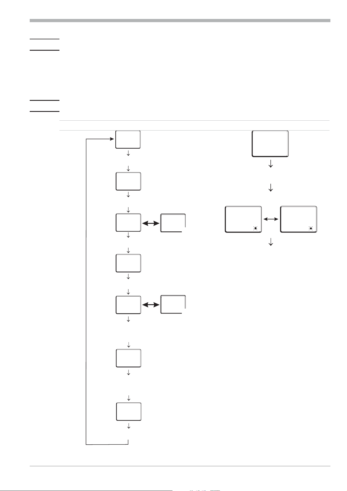
3.7 Operating structure
After supply voltage switch-on, the controller starts with the operating levels.
The controller status is as before power off.
126
Ù
125
3sec.
126
PArA
Ì
Ù
126
ConF
Ì
PASS
Ù
126
CAL
Ì
PASS
Ù
126
End
PASS
Ù
g
g
PArA - level: At PArA - level, the right decimal point of the upper
display line is lit continuously.
ConF - level: At ConF - level, the right decimal point of the upper
display line blinks.
All levels are only accessible by entry of the password PASS .
PASS
Factory setting:
Safety switch
Loc
closed OFF / password disabled / enabled
open OFF / password disabled
open OFF enabled
open Password enabled
When safety switch Loc is open, no access to all levels is possible.
Safety switch Loc closed: all levels accessible without
restriction, password PASS = 45.
Password entered with
BluePort®
Function disabled or enabled
with BluePort®
Access via the instrument
front panel:
enabled
disabled
enabled
enabled after password
entry
TB40-1 13 Operating structure
Page 14

Configuration level
4 Configuration level
4.1 Configuration survey
ConF Configuration level
Lim
Limit value functions
È
Fnc.1 StYP O.Act O.Act Err.r Unit
Ì
Fnc.2 S.Lin dP
Src.2 Corr diSP
Fnc.3
Src.3
InP.1
Input 1
OUt.2
Output 2
OUt.3
Output 3
LOGI
Digital inputs
Othr
Display
End
g
+
Adjustment:
The configuration can be adjusted by means of keys ÈÌ .
w
Transition to the next configuration is by pressing key Ù .
w
After the last configuration of a group, donE is displayed and followed by
w
automatic change to the next group
Return to the beginning of a group is by pressing the Ù key for 3 sec.
Configuration survey 14 TB40-1
Page 15

Configuration level
4.2 Configuration
Lim
Name Value range Description Default
Fcn.1
Fcn.2 / 3
Src.2 / 3
Hour
Swit
5
6
7
8
0
1
2 Measured value monitoring + latching of the alarm status.
0
1
OFF...10000
OFF...10000
Function of limit 1
Measured value monitoring upper limit (no latching)
Measured value monitoring lower limit (no latching)
Measured value monitoring + latching of the alarm status of
the upper limit. A latched alarm can be reset by the error
list, the digital input or the RESET-key (-> LOGI/
Err.r).
Measured value monitoring + latching of the alarm status of
the lower limit. A latched alarm can be reset by the error
list, the digital input or the RESET-key (-> LOGI/
Err.r).
Function of limit2/3
switched off
measured value monitoring
A latched alarm can be reset by the error list, the digital
input DI1 or the RESET-key (-> LOGI/ Err.r).
Source of limit2/3
process value
control deviation xw (process value - set-point)
Operating hours (only visible with BlueControl!)
Output switching cycles (only visible with BlueControl!)
7
TW
1
TW
1
TB
1
TB
1
0/0
0/0
OFF
OFF
+
1 TW: Temperature monitor
TB: Temperature limiter
Fcn.3, Src.3 only available if Fcn.1 is configured as TW
InP.1
Name Value range Description Default
S.tYP
2
3
4
5
6
7
8
9
10
18
Sensor type selection
0
1
thermocouple type L (-100...900°C), Fe-CuNi (DIN)
thermocouple type J (-100...1200°C), Fe-CuNi
thermocouple type K (-100...1350°C), NiCr-Ni
thermocouple type N (-100...1300°C), Nicrosil-Nisil
thermocouple type S (0...1760°C), PtRh-Pt10%
thermocouple type R (0...1760°C), PtRh-Pt13%
thermocouple type T (-200...400°C), Cu-CuNi
thermocouple type C (0...2315°C), W5%Re-W26%Re
thermocouple type D (0...2315°C), W3%Re-W25%Re
thermocouple type E (-100...1000°C), NiCr-CuNi
thermocouple type B (0/100...1820°C), PtRh-Pt6%
special thermocouple
1
TB40-1 15 Configuration
Page 16

Configuration level
Name Value range Description Default
S.Lin
Corr
20
21
22
23
24
30
40
Pt100 (-200.0 ... 100,0 °C)
Pt100 (-200.0 ... 850,0 °C)
Pt1000 (-200.0 ... 850.0 °C)
special 0...4500 Ohm (preset to KTY11-6 )
special 0...450 Ohm
0...20mA / 4...20mA 1
0...10V / 2...10V 1
Linearization (only at S.tYP = 23 (KTY 11-6), 24
(0...450
0
1
none
Linearization to specification. Creation of linearization table
W), 30 (0..20mA), 40 (0..10V) and 41 (0...100mV) )
0
with engineering tool possible. The characteristic for KTY
11-6 temperature sensors is preset.
Measured value correction / scaling
0
1
2
3
Without scaling
Offset correction (at CAL level)
2-point correction (at CAL level)
Scaling (at PArA level)
0
+
1 with current and voltage input signals, scaling is required
(see chapter 5.3)
For application as temperature limiter for one thermocouple a dual
thermocpouple must be connected
Out.1
Name Value range Description Default
O.Act
Method of operation OUT1
0
1
direct / normally open
inverse / normally closed
0
Out.2 only available if Fcn.1=TW
Name Value range Description Default
O.Act Method of operation OUT2
0
1
direct / normally open
inverse / normally closed
0
LOGI
Name Value range Description Default
Err.r
2
6
Configuration 16 TB40-1
Reset of all limit alarms
DI1
RESET- key
6
Page 17

Configuration level
othr
Name Value range Description Default
Unit
dP
diSP
C.dEl
FrEq
0
1
2
0
1
2
3
0
1
2
3
4
0..200
0
1
Unit
without unit
°C
°F
Decimal point (max. number of digits behind the decimal
point)
No digit behind the decimal point
1 digit behind the decimal point
2 digits behind the decimal point
3 digits behind the decimal point
Type of measured value display
No measured value display
Full display resolution
Display resolution: 2 digits
Display resolution: 5 digits
Display resolution: 10 digits
Modem delay [ms]
Switching 50 Hz / 60 Hz (only visible with BlueControl!)
50 Hz
60 Hz
1
0
1
0
0
g
+
Resetting the device configuration to factory setting (Default)
r chapter 10.1 (page 30)
BlueControl - the engineering tool for the BluePortâcontroller series
3 engineering tools with different functionality facilitating TB40-1 configuration
and parameter setting are available (see chapter 8: Accessory equipment with or
dering information).
In addition to configuration and parameter setting, the engineering tools are used
for data acquisition and offer long-term storage and print functions. The enginee
ring tools are connected to TB40-1 via the front-panel interface "BluePort
â
"by
means of PC and a PC adaptor.
Description BlueControl: see chapter 7: BlueControl (page 23).
-
-
TB40-1 17 Configuration
Page 18

Parameter setting level
5 Parameter setting level
5.1 Parameter survey
PArA Parameter setting level
Lim
Limit value functions
InP.1
È
LC InL.1 rnGL
Ì
L.2 OuL.1 rnGH
H.2 InH.1
HYS.2 OuH.1
L.3 tF.1
H.3
HYS.3
Input 1
rnG
LC setting range
End
g
Adjustment:
The parameters can be adjusted by means of keys ÈÌ
w
Transition to the next parameter is by pressing key Ù
w
After the last parameter of a group, donE is displayed, followed by
w
automatic change to the next group.
+
Return to the beginning of a group is by pressing the Ù key for 3 sec.
5.2 Parameters
Lim
Name Value range Description Default
LC
L.2
H.2
HYS.2
L.3
H.3
HYS.3
-1999...9999
-1999...9999
-1999...9999
0...9999
-1999...9999
-1999...9999
0...9999
LC limit
Lower limit 2
Upper limit 2
Hysteresis limit 2
Lower limit 3
Upper limit 3
Hysteresis limit 3
100
OFF
OFF
1
OFF
OFF
1
L.3, H.3, Hys.3 only available if Fcn.1=TW
InP.1
Name Value range Description Default
InL.1
OuL.1
InH.1
OuH.1
t.F1
Parameter survey 18 TB40-1
-1999...9999
-1999...9999
-1999...9999
-1999...9999
-1999...9999
Input value for the lower scaling point
Displayed value for the lower scaling point
Input value for the upper scaling point
Displayed value for the upper scaling point
Filter time constant [s]
0
0
20
20
0,5
Page 19

Parameter setting level
rnG
Name Value range Description Default
rnG.L
rnG.H
-1999...9999
-1999...9999
Set-point limit low for set-point LC
Set-point limit high for set-point LC
-1999
9999
g
Resetting the device configuration to factory setting (Default)
r chapter 10.1 (page 30)
5.3 Input scaling InP.1
When using current or voltage signals as input variables for InP.1 scaling of
input and display values at parameter setting level is required. Specification of
the input value for lower and higher scaling point is in the relevant electrical unit
(mA/ V).
mA / V
phys.
quantity
OuH.x
OuL.x
InL.x
InH.x
phys. quantity
mA/V
g
a
g
Parameters InL.1 , OuL.1, InH.1 and OuH.1 are only visible if
ConF / InP.1 / Corr = 3 is chosen.
S.tYP Input signal InL.1 OuL.1 InH.1 OuH.1
30
(0...20mA)
40
(0...10V)
0…20mA 0 any 20 any
4…20mA 4 any 20 any
0…10V 0 any 10 any
2…10V 2 any 10 any
In addition to these settings, InL.1 and InH.1 can be adjusted in the range
(0...20mA / 0...10V) determined by selection of S.tYP .
For using the predetermined scaling with thermocouple and resistance
thermometer (Pt100), the settings for InL.1 and OuL.1 and for InH.1 and
OuH.1 must have the same value.
Input scaling changes at calibration level (r page 20) are displayed by input
scaling at parameter setting level. After calibration reset (OFF), the scaling
parameters are reset to default.
TB40-1 19 Input scaling InP.1
Page 20

Calibration level
6 Calibration level
g
Measured value correction ( CAL) is only visible if ConF / InP.1 / Corr = 1
or 2 is chosen.
The measured value can be matched in the calibration menu ( CAL). Two me
-
thods are available:
Offset correction
( ConF/ InP.1 / Corr =1 ):
possible on-line at the
w
display
standard setting
offset correction
process
OuL.1
new
OuL.1old
2-point correction
( ConF/ InP.1 / Corr = 2 ):
w
is possible off-line with
process value simulator
display
OuH.1
OuH.1
OuL.1
new
OuL.1old
old
new
InL.1
InL.1
standard setting
2-point correction
InH.1
X
X
20 TB40-1
Page 21

Offset correction ( ConF/ InP.1 / Corr =1 ):
°C
Err
°F
r
Calibration level
126
125
r
Ù
3sec.
r
PArA
Ì
:
CAL
r
InL.1: The input value of the scaling point is displayed.
The operator must wait, until the process is at rest.
Subsequently, the operator acknowledges the input value by pressing
key Ù.
OuL.1: The display value of the scaling point is displayed.
Before calibration, OuL.1 is equal to InL.1.
The operator can correct the display value by pressing keys ÈÌ .
Subsequently, he confirms the display value by pressing key Ù.
Ù
r
InP.1
r
Ù
r
r
r
InL.1
OuL.1
End
r
r
È
Ì
Ù
r
Ù
Ù
TB40-1 21
Page 22

Calibration level
°C
Err
°F
2-point correction ( ConF/ InP.1 / Corr = 2):
r
126
125
r
Ù
3sec.
r
PArA
Ì
:
CAL
r
InL.1: The input value of the lower scaling point is displayed.
The operator must adjust the lower input value by means of a
process value simulator and confirm the input value by pressing key Ù.
OuL.1: The display value of the lower scaling point is displayed.
Before calibration, OuL.1 equals InL.1.
The operator can correct the lower display value by pressing the ÈÌ
keys. Subsequently, he confirms the display value by pressing key Ù.
InH.1: The input value of the upper scaling point is displayed. .
The operator must adjust the upper input value by means of the
process value simulator and confirm the input value by pressing key Ù.
OuH.1: The display value of the upper scaling point is displayed.
Before calibration OuH.1 equals InH.1.
The operator can correct the upper display value by pressing keys ÈÌ
Subsequently, he confirms the display value by pressing key Ù.
Ù
r
InP.1
r
Ù
r
r
r
r
r
InL.1
OuL.1
InH.1
OuH.1
End
r
È
Ì
r
È
Ì
r
Ù
r
Ù
r
Ù
Ù
Ù
g
The parameters (OuL.1, OuH.1) changed at CAL level can be reset by adjusting
the parameters below the lowest adjustment value (OFF) by means of decrement
key Ì .
22 TB40-1
Page 23

BlueControl
7 BlueControl
BlueControl is the projection environment for the BluePortâcontroller series of
PMA. The following 3 versions with graded functionality are available:
The mini version is - free of charge - at your disposal as download at PMA homepage www.pma-online.de or on the PMA-CD (please ask for).
At the end of the
installation the li
cence number has
to be stated or
DEMO mode
must be chosen.
At DEMO mode
the licence num
ber can be stated
subsequently un
der Help r Li
cence r Change.
-
-
-
-
TB40-1 23
Page 24

Versions
8 Versions
TB40 1 00
Flat pin connectors
Screw terminal connectors
90..250V AC, 3 relays, 0
24VAC / 18..30VDC, 3 relays, 1
90..250V AC, 2 relays,
24VAC / 18..30VDC, 2 relays,
TW
TW
TB
TB
2)
2)
0
0
1
1)
1)
2
3
Standard configuration 0
Configuration to specification 9
No manual 0
Manual German D
Manual English E
Manual French F
Standard CE-certified) 0
cULus certified (with screw terminals only!) U
3)
EN14597 certified (replaces DIN 3440)
D
Standard version 00
Customer specification ..
1) Temperature monitor
2) TB (EN14597, 2009-1), not available with cULusTemperature limiter
3) Not available as Temperature limiter TB (EN14597, 2009-1)
Accessories delivered with the unit
Operating manual (if selected by the ordering code)
2 fixing clamps
w
operating note in 15 languages
w
Accessory equipment with ordering information
Description Order no.
PC-adaptor for the front-panel interface 9407-998-00001
Standard rail adaptor 9407-998-00061
Operating manual German 9499-040-93418
Operating manual English 9499-040-93411
BlueControl (engineering tool) Mini Download www.pma-online.de
BlueControl (engineering tool) Basic 9407-999-11001
BlueControl (engineering tool) Expert 9407-999-11011
24 TB40-1
Page 25

Technical data
9 Technical data
INPUTS
PROCESS VALUE INPUT INP1
Resolution: > 14 bits
Decimal point: 0 to 3 digits behind the decimal point
Dig. input filter: adjustable 0,000...9999 s
Scanning cycle: 100 ms
Measured value
correction:
Thermocouples
r Table 1 (page 27 )
If the device is used as a teperature limiter, a
double thermocouple must be connected. For
measurements in the area of ambient
temperature (0mV) the plausibility is ensured
by the control of the 2nd thermocouple.
Outside of this range there is no check of the
2nd thermocouple.
Input resistance: ³ 1MW
Effect of source resistance: 1 mV/W
2-point or offset correction
CONTROL INPUT DI1
Configurable as switch or push-button!
Connection of a potential-free contact suitable
for switching “dry” circuits.
Switched voltage: 2,5 V
Current: 50 mA
GALVANIC ISOLATION
Safety isolation
Function isolation
Power supply connections Process value input INP1
Digital input di1
Relay outputs OUT 1,2
Relay output OUTLC
OUTPUTS
OUTPUT LC
Function:
Interruption of the power supply if the set limit
is exceeded or fallen short.
Cold-junction compensation
Maximal additional error: ± 0,5 K
Sensor break monitoring
Sensor current: £1 mA
Configurable output action
Resistance thermometer
r Table 2 (page 27 )
Connection: 2 or 3-wire
Lead resistance: max. 30 Ohm
Input circuit monitor: break and short circuit
Special measuring range
BlueControl (engineering tool) can be used to
match the input to sensor KTY 11-6
(characteristic is stored in the controller).
Physical measuring range: 0...4500 Ohm
Linearization segments 16
Current and voltage signals
r Table 3 (page 27 )
Span start, end of span: anywhere within measuring range
Scaling: selectable -1999...9999
Linearization: 16 segments, adaptable with
BlueControl
Decimal point: adjustable
Input circuit monitor: 12,5% below span start (2mA, 1V)
Contact type: potential-free changeover contact
Max.contact rating: 500 VA, 250 V, 2A at 48...62 Hz,
resistive load
Min. contact rating: 5V, 10 mA AC/DC
Operating life (electr.): 600.000 duty cycles with max.
contact rating
If the device is used as temperature limiter
(configuration date Fcn.1 = 7 or 8) the bridge
between clamps 6 and 7 must not be removed!
The bridge ensures the safe interruption of power by
serial switching of the relays LC and OUT2. If the
device is utilized as temperature monitor
(configuration date Fcn.1=5or6)thebridge
can be removed, the break is only via LC relay
OUTPUTS OUT1, OUT2
Function:
Additional alarms with MAX, MIN or MAX+MIN
monitoring with adjustable hysteresis.
Monitored signals:
w
process value (absolut)
w
difference to the limit (relative)
w
sensor break / short circuit
According to the input type, the input signal is
monitored to sensor break, polarity error and
short circuit
TB40-1 25
Page 26

Technical data
Contact type: 2 NO contacts with common
connection
Max. contact rating: 500 VA, 250 V, 2A at 48...62 Hz,
resistive load
Min. contact rating: 6V, 1 mA DC
Operating life (electr.): 800.000 duty cycles with max. rating
Note:
If the relays OUT1...OUT LC operate external
contactors, these must be fitted with RC
snubber circuits to manufacturer specifications
to prevent excessive switch-off voltage peaks.
POWER SUPPLY
Dependent of order
AC SUPPLY
Voltage: 90...250 V AC
Frequency: 48...62 Hz
Power consumption approx. 7.3 VA
UNIVERSAL SUPPLY 24 V UC
AC voltage: 20,4...26,4 V AC
Frequency: 48...62 Hz
DC voltage: 18...31 V DC
Power consumption: approx.. 7.3 VA
BEHAVIOUR WITH POWER FAILURE
Configuration, parameters and adjusted
set-points, control mode:
Non-volatile storage in EEPROM
Humidity
75% yearly average, no condensation
Altitude
To 2000 m above sea level
Shock and vibration
Vibration test Fc (DIN 68-2-6)
Frequency: 10...150 Hz
Unit in operation: 1g or 0,075 mm
Unit not in operation: 2g or 0,15 mm
Shock test Ea (DIN IEC 68-2-27)
Shock: 15g
Duration: 11ms
Electromagnetic compatibility
Complies with EN 61 326-1
(for continuous, non-attended operation)
GENERAL
Housing
Material: Makrolon 9415 flame-retardant
Flammability class: UL 94 VO, self-extinguishing
Plug-in module, inserted from the front
Safety test
Complies with EN 61010-1 (VDE 0411-1):
Overvoltage category II
Contamination class 2
Working voltage range 300 V
Protection class II
BLUEPORT FRONT INTERFACE
Connection of PC via PC adapter (see
"Accessory equipment"). The BlueControl
software is used to configure, set parameters
and operate the TB40-1.
ENVIRONMENTAL CONDITIONS
Protection modes
Front panel: IP 65 (NEMA 4X)
Housing: IP 20
Terminals: IP 00
Permissible temperatures
For specified accuracy: 0...60°C
Warm-up time: ≥ 15 minutes
For operation: -20...65°C
For storage: -40...70°C
Certifications
Type tested to EN 14597 (2009-1)
With certified sensors applicable for:
w
Heat generating plants with outflow
temperatures up to 120°C to DIN 4751
w
Hot-water plants with outflow temperatures
above 110°C to DIN 4752
w
Thermal transfer plants with organic transfer
media to DIN 4754
w
Oil-heated plants to DIN 4755
Electrical connections
According to order:
w
- flat-pin terminals 1 x 6,3mm or 2 x 2,8mm
according to DIN 46 244 or
- screw terminals from 0,5 to 2,5mm².
26 TB40-1
Page 27

Technical data
Mounting
Panel mounting with two fixing clamps at
top/bottom or right/left. High-density mounting
possible
Mounting position: uncritical
Weight: 0,27kg
Accessories delivered with the unit
Operating manual
Fixing clamps
Table 1 Thermocouple measuring ranges
Type Range Accuracy Resolution (Ô)
L Fe-CuNi (DIN) -100...900°C -148...1652°F ß 2K 0,1 K
J Fe-CuNi -100...1200°C -148...2192°F ß 2K 0,1 K
K NiCr-Ni -100...1350°C -148...2462°F ß 2K 0,2 K
N Nicrosil/Nisil -100...1300°C -148...2372°F ß 2K 0,2 K
S PtRh-Pt 10% 0...1760°C 32...3200°F ß 2K 0,2 K
R PtRh-Pt 13% 0...1760°C 32...3200°F ß 2K 0,2 K
T Cu-CuNi -200...400°C -328...752°F ß 2K 0,05 K
C W5%Re-W26%Re 0...2315°C 32...4199°F ß 2K 0,4 K
D W3%Re-W25%Re 0...2315°C 32...4199°F ß 2K 0,4 K
E NiCr-CuNi -100...1000°C -148...1832°F ß 2K 0,1 K
B * PtRh-Pt6% 0(100)...1820°C 32(212)...3308°F ß 2K 0,3 K
* Specifications valid from 400°C
Table 2 Resistance transducer measuring ranges
Type Sens. current Range Accuracy Resolution (Ô)
Pt100
Pt100 -200...850°C -140...1562°F ß 1K 0,1K
0,2mA
Pt1000 -200...850°C -140...392°F ß 2K 0,1K
-200...100°C -140...212°F ß 1K 0,1K
KTY 11-6 * -50...150°C -58...302°F ß 2K 0,05K
* Or special
Table 3 Current and voltage measuring ranges
Range Input resistance Accuracy Resolution (Ô)
0-10 Volt ~ 110 kW ß 0,1 % ß 0,6 mV
0-20 mA 49 W (voltage requirement ß 2,5 V) ß 0,1 % ß 1,5 mA
TB40-1 27
Page 28

Safety hints
10 Safety hints
+
This unit was built and tested in compliance with VDE 0411-1 / EN 61010-1 and
was delivered in safe condition.
The unit complies with European guideline 89/336/EWG (EMC) and is provided
with CE marking.
The unit was tested before delivery and has passed the tests required by the test
schedule. To maintain this condition and to ensure safe operation, the user must
follow the hints and warnings given in this operating manual.
The unit is intended exclusively for use as a measurement and control instrument
in technical installations.
Modified definition according to EN 14597 (former DIN 3440)
“Temperature control devices and temperature limiters for
heat generating systems”
After introduction of this new standard (2005-12) the definitions
described therein were changed again. According to the latest
release (EN14597, 2009-1) a temperature limiter TB is no longer
considered as operating equipment (as a temperature monitor TW)
but as protective equipment (!) which needs to meet higher
requirements
The most important requirement for a TB has now been added:
Any device or component must be failsafe and the supply to the
plant switched off!
a
Warning
If the unit is damaged to an extent that safe operation seems impossible, the unit
must not be taken into operation.
ELECTRICAL CONNECTIONS
The electrical wiring must conform to local standards (e.g. VDE 0100). The input
measurement and control leads must be kept separate from signal and power
supply leads.
In the installation of the controller a switch or a circuit-breaker must be used and
signified. The switch or circuit-breaker must be installed near by the controller
and the user must have easy access to the controller.
COMMISSIONING
Before instrument switch-on, check that the following information is taken into
account:
Ensure that the supply voltage corresponds to the specifications on the type
w
label.
All covers required for contact protection must be fitted.
w
28 TB40-1
Page 29

Safety hints
If the controller is connected with other units in the same signal loop, check
w
that the equipment in the output circuit is not affected before switch-on. If
necessary, suitable protective measures must be taken.
The unit may be operated only in installed condition.
w
Before and during operation, the temperature restrictions specified for
w
controller operation must be met.
SHUT-DOWN
For taking the unit out of operation, disconnect it from all voltage sources and
protect it against accidental operation.
If the controller is connected with other equipment in the same signal loop, check
that other equipment in the output circuit is not affected before switch-off. If ne
cessary, suitable protective measures must be taken.
MAINTENANCE, REPAIR AND MODIFICATION
The units do not need particular maintenance.
-
a
l
a
Warning
When opening the units, or when removing covers or components, live parts and
terminals may be exposed.
Before starting this work, the unit must be disonnected completely.
After completing this work, re-shut the unit and re-fit all covers and components.
Check if specifications on the type label must be changed and correct them, if necessary.
Caution
When opening the units, components which are sensitive to electrostatic dischar
ge (ESD) can be exposed. The following work may be done only at workstations
with suitable ESD protection.
Modification, maintenance and repair work may be done only by trained and aut
horized personnel. For this purpose, the PMA service should be contacted.
The cleaning of the front of the controller should be done with a dry or a wetted
(spirit, water) kerchief.
-
-
TB40-1 29
Page 30

Safety hints
10.1 Resetting to factory setting
In case of faulty configuration, TB40-1 can be reset to ist factory the default con
dition.
4
1
ÌÈ + Power on
FAC
°C
torY
1.
°F
Err
2
È
FAC
YES
3
Ù
FAC
°C
°F
Err
5
PASS
°C
°F
Err
FAC
FAC
no
°C
°F
Err
COPY
°C
°F
Err
-
g
g
2.
8.8.8.8.
8.8.8.8.
1
For this, the operator must keep the keys increment and decrement pressed during power-on:
ÈÌ
2
For confirmation, press key increment to select YES.
3
Press the key enter to go to the password input.
4
After setting a valid password the factory resetting is confirmed with Enter
and the copy procedure is started (display COPY).
5
Afterwards the device restarts.
In all other cases, no reset will occur(timeout abortion).
If the safety lock is open then factory resetting is not possible.
The copy procedure (COPY) can take some seconds.
Now, the transmitter is in normal operation.
°C
°F
Err
Resetting to factory setting 30 TB40-1
Page 31

Index
M
!
2-point correction............20
A
Accessory equipment..........24
Additional alarms............12
Alarm handling ..........11-12
B
BlueControl...............23
C
Calibration level ..........20-22
Certifications ..............26
Configuration level ........14-17
Connecting diagramm ........5-6
Connecting example ...........6
Current signal measuring range ....25
D
Digital input di1
Configuration ..........16
Technical data ..........25
E
Engineering tool ............17
Environmental conditions .......26
Error list ................10
Error status ...............11
Extended operating level ........9
F
Front view ................8
H
Maintenance manager .........10
Method of operation limit value LC . . 11
Mounting.................4
O
Offset correction ............20
Output OUT1
Configuration ..........16
Technical data ..........25
Output OUT2
Configuration ..........16
Technical data ..........25
P
Parameter setting level ......18-19
Power supply ..............26
R
RESET key................8
Resetting to factory setting .......30
Resistance thermometer measuring range
.....................25
S
Safety hints ............28-30
Safety switch...............4
Setting of limit value LC ........9
T
Thermocouple measuring range ....25
V
Versions ................24
Voltage signal measuring range ....25
Housing .................26
I
Input INP1
Configuration ..........15
Parameter setting ........18
Technical data ..........25
Input scaling ..............19
L
LC alarm ................11
LED
°C.................8
°F.................8
Err-LED.............8
LED colours............8
TB40-1 31
Page 32

2
9499- 040- 93411
Subject to alterations without notice © PMA Prozeß- und Maschinen-Automation GmbH
Änderungen vorbehalten P.O.B. 310 229, D-34058 Kassel, Germany
Sous réserve de toutes modifications Printed in Germany 9499-040-93411 (08/2013)
A5 auf A6 gefaltet, 2-fach geheftet, SW-Druck Normalpapier weiß 80g/m
A6
 Loading...