

Page 1
User Manual
Relay C
3PH from 60A to 210A
Rev. 01/2019
PMA-C3-60-210A
www.west-cs.co.uk
Page 2

A publication of:
PMA
Prozeß- und Maschinen-Automation GmbH
P.O.Box 310 229 • D-34058 Kassel • Germany
All rights reserved.
No part of this document may be reproduced or published in any form or by any means without
prior written permission from the copyright owner.
Liability and warranty
Any information and notes in these operating instructions were composed under consideration of
the applicable regulations, the present state of the art and our extensive know-how and experience.
With special versions, additional ordering options or due to the latest technical modications, the
actual scope of delivery may vary from the descriptions and drawings in this manual.
For questions, please, contact the manufacturer.
Before starting to work with the instrument and before commissioning, in particular, these
operating instructions must be read carefully! The manufacturer cannot be held responsible
for damage and trouble resulting from failure to comply with the information given in this
manual.
This product may be subject to change due to improvements of the product features in the
course of further development.
Copyright
This operating manual should be considered as condential information, intended only for persons
who work with the instrument.
Contraventions are subject to payment of damages. Further claims reserved.
www.west-cs.co.uk 2
Page 3

Contents
1. Important warnings for safety .............................................................................................................................. 5
2. Maintenance ........................................................................................................................................................... 10
3. Introduction ............................................................................................................................................................ 11
A thyristor unit is semiconductor device which acts as a switch formed by two thyristors in ant parallel. .... 11
3.1. Advantages compared with analog thyristor unit ........................................................................................... 11
3.2. Overview ............................................................................................................................................................. 12
4. Software Congurator ........................................................................................................................................... 13
Thyristor congurator software is free and is Thyristor congurator software is free and is .......................... 13
5. Quick Start ............................................................................................................................................................. 14
6. Basic Connections and sizing.............................................................................................................................. 15
7. Identication .......................................................................................................................................................... 16
7.1. Identication of the unit ..................................................................................................................................... 16
8. Order Code ............................................................................................................................................................. 17
8.1. Notes on the options: ......................................................................................................................................... 18
8.1.1 I LIMIT (CURRENT LIMIT) ............................................................................................................................... 18
8.1.2. Heaterbreak Alarm (HB) .................................................................................................................................... 18
8.1.3. Datalogger ......................................................................................................................................................... 18
8.1.4. Energy totalizer .................................................................................................................................................. 18
9. Technical specications ....................................................................................................................................... 19
9.1. General features ................................................................................................................................................. 19
9.2. Input features ...................................................................................................................................................... 19
9.3. Output features (power device)......................................................................................................................... 19
9.4. Fan Specication (only from 90 to 210A) ......................................................................................................... 19
9.5. Environmental installation conditions ............................................................................................................. 20
9.6. Derating curve .................................................................................................................................................... 20
9.7. Calculating ow capacity of the fan ................................................................................................................. 20
10. Installation............................................................................................................................................................ 21
10.1. Dimensions and weight ................................................................................................................................... 22
10.2. Fixing holes ........................................................................................................................................................ 22
11. Wiring instructions .............................................................................................................................................. 23
11.1. Terminal Positions ............................................................................................................................................ 23
11.2. Power Terminals ............................................................................................................................................... 23
11.3. Control Terminals ............................................................................................................................................. 24
11.3.1. Terminal block M1 ............................................................................................................................................ 24
11.3.2. Terminal block M3 ........................................................................................................................................... 24
11.4. Schematic .......................................................................................................................................................... 25
11.4.1 SSR Control Input Schematic .......................................................................................................................... 26
11.5 Connection Diagram for 3 phases ................................................................................................................... 27
12. Control Panel ...................................................................................................................................................... 28
12.1. Menu navigation ............................................................................................................................................... 29
12.2. Control Panel Led ............................................................................................................................................. 30
12.3. Displayed alarms .............................................................................................................................................. 30
12.4. Parameter list .................................................................................................................................................... 31
12.4.1 Operator Menu .................................................................................................................................................. 31
12.5 Setup Menu ........................................................................................................................................................ 32
12.5.2 Advanced Setup Menu ..................................................................................................................................... 32
12.5.3 Hardware Menu ................................................................................................................................................ 34
12.5.4. Communication Menu ..................................................................................................................................... 37
12.5.5 Monitoring Menu .............................................................................................................................................. 38
13. Using the Congurator ....................................................................................................................................... 41
13.1 Typical Uses ..................................................................................................................................................... 41
13.2 Communicating with Power Controllers ......................................................................................................... 41
13.3 Recipes ............................................................................................................................................................... 41
13.3.1 Upload a recipe ................................................................................................................................................ 41
13.3.2 Download a recipe............................................................................................................................................ 41
13.4 How To ................................................................................................................................................................ 41
13.4.1 Install and communication with the power controller ...................................................................................... 41
13.5 Using the Congurator ..................................................................................................................................... 42
13.5.1 To view or save a power controller’s settings ................................................................................................... 42
using “Simple” view section: ........................................................................................................................................ 42
13.5.2 To edit a setting in a recipe: ............................................................................................................................. 43
13.5.3 To download a recipe le into a power controller: ............................................................................................ 43
13.5.4 To monitor a power controller with the Test view: ............................................................................................ 43
www.west-cs.co.uk 3
Page 4

13.5.5 To log in on the test view to change the digital input and analog input functions: ............................................ 43
13.5.6 To log out the test view: .................................................................................................................................... 43
13.5.7 To view data on the scope: ............................................................................................................................... 44
13.5.8 To reset the power totals: ................................................................................................................................. 44
13.5.9 Setting Up and Using Data Logging ................................................................................................................. 44
13.5.10 To retrieve a data log le from the power controller: ...................................................................................... 45
13.6 Software General information .......................................................................................................................... 45
13.6.1 Program Window .............................................................................................................................................. 45
13.6.2 Simple Section ................................................................................................................................................. 45
13.6.3 Test Section ...................................................................................................................................................... 46
13.6.4. Load Analyzer .................................................................................................................................................. 48
13.6.5 Data Log Window ............................................................................................................................................. 49
13.6.6 Data Log Conguration window ....................................................................................................................... 49
13.6.7 MSG view ......................................................................................................................................................... 50
13.6.8 Settings window ............................................................................................................................................... 50
14. Firing type ............................................................................................................................................................ 51
14.1 Zero Crossing .................................................................................................................................................... 51
14.2 Single Cycle ....................................................................................................................................................... 51
14.3 Burst Firing ........................................................................................................................................................ 51
14.4 Soft Start with Burst Firing ............................................................................................................................... 52
14.5 Phase Angle ....................................................................................................................................................... 52
14.6 Soft Start with Phase Angle .............................................................................................................................. 52
14.7 Delay Triggering with Burst Firing ................................................................................................................... 53
15. Current Limit ........................................................................................................................................................ 54
15.1 Current Limit Setting ......................................................................................................................................... 54
15.2 Current Limit tuning procedure ....................................................................................................................... 54
16. Bakeout in function ............................................................................................................................................. 55
16.1 What is heater bakeout? ................................................................................................................................... 55
16.2 How does heater bakeout work? ..................................................................................................................... 55
17. Control Mode (feed-back) ................................................................................................................................... 56
18. Supply the Electronic Board .............................................................................................................................. 57
19. RS485 Serial port ................................................................................................................................................. 58
20. Fieldbus communication option ....................................................................................................................... 58
21. Internal Fuse ........................................................................................................................................................ 59
www.west-cs.co.uk 4
Page 5
1. Important warnings for safety
IND. CONT. EQ.
E231578 2RD5
This chapter contains important information for the safety. The not observance of these instructions may result
in serious personal injury or death and can cause serious damages to the Thyristor unit and to the components
system included.
The installation should be performed by qualied persons.
In the manual are used symbols to give more evidence at the notes of safety and operativity for the attention
for the user:
This icon is present in all the operational procedures where the Improper operation may result in serious
personal injury or death by Electrical Shock Hazard Symbol (a lightning bolt in a triangle) precedes an
electric shock hazard CAUTION or WARNING safety statement.
Warning or Hazard that needs further explanation than the label on unit can provide. Consult User’s Guide
for further information.
Unit is compliant with European Union directives.
See Declaration of Conformity for further details on Directives and Standards used for Compliance.
If available, unit is a Listed device per Underwriters Laboratories. It has been investigated to ANSI/UL®
508 standards for Industrial Control Switches and equivalent to CSA C22.2 #14.
For more detail search for File E505847 on www.ul.com
ESD Sensitive product, use proper grounding and handling techniques when installing or servicing product.
Do not throw in trash, use proper recycling techniques or consult manufacturer for proper disposal.
www.west-cs.co.uk 5
Page 6

A “NOTE” marks a short message to alert you to an important detail.
A “CAUTION” safety alert appears with information that is important for protecting your equipment and performance.
Be especially careful to read and follow all cautions that apply to your application.
A “WARNING” safety alert appears with information that is important for protecting you, others and equipment
from damage. Pay very close attention to all warnings that apply to your application.
1.1. Safety notes
WARNING! To avoid damage to property and equipment, injury and loss of life, adhere to applicable electrical
codes and standard wiring practices when installing and operating this product. Failure to do so could result in
damage, injury and death.
WARNING! All service including inspection, installation, wiring, maintenance, troubleshooting, fuse or other user
serviceable component replacement must be performed only by properly qualied personnel. Service personnel
must read this manual before proceeding with work. While service is being performed unqualied personnel
should not work on the unit or be allowed in the immediate vicinity.
WARNING! When in use the power controller is connected to dangerous voltages. Do not remove the protective
covers without rst disconnecting and preventing power from being restored while servicing the unit.
WARNING! Do not use in aerospace or nuclear applications.
WARNING! The power controller’s protection rating is IP20 with all covers installed and closed. It must be
installed in an enclosure that provides all the necessary additional protections appropriate for the environment
and application.
WARNING! Ground the power controller via the provided protective earth grounding terminal. Verify ground is
within impedance specications. This should be veried periodically.
WARNING! Electric Shock Hazard: when the power controller has been energized, after shutting o the power,
wait at least one minute for internal capacitors to discharge before commencing work that brings you in to
contact with power connections or internal components.
WARNING! The installation must be protected by electromagnetic circuit breakers or by fuses. The
semiconductor fuses located inside the power controller are classied for UL as supplementary protection for
semiconductor devices. They are not approved for branch circuit protection.
WARNING! When making live voltage or current measurements, use proper personal protective equipment for
the voltages and arc-ash potentials involved.
WARNING! Verify the voltage and current ratings of the power controller are correct for the application.
www.west-cs.co.uk 6
Page 7

CAUTION: To avoid compromising the insulation, do not bend wire or other components beyond their bend
radius specications.
CAUTION: Protect the power controller from high temperature, humidity and vibrations.
CAUTION: The power controller warranty is void if the tested and approved fuses are not used.
CAUTION: Only trained and authorized personnel should access and handle the internal electronics and they
must follow proper electro-static prevention procedures.
CAUTION: Install an appropriately sized RC lter across contactor coils, relays and other inductive loads.
NOTE! Provide a local disconnect to isolate the power controller for servicing.
NOTE! The nominal current is specied for ambient temperatures at or below 40° C. Ensure the application
design allows for adequate cooling of each power controller. The power controller must be mounted vertically.
The cooling design must prevent air heated by one power controller from causing power controllers mounted
above to exceed the ambient operating temperature limit. When power controllers are mounted side by side
allow a minimum spacing of 15mm between them.
NOTE! Use only copper cables and wires rated for use at 90°C or greater.
www.west-cs.co.uk 7
Page 8

2. Maintenance
In order to have a corrected cooling, the user must clean the heat-sink and the protective grill of the fans. The frequency of this servicing depends on environmental pollution.
Also check periodically if the screw for the power cables and safety earth are tightened correctly
(See Connection Diagram).
www.west-cs.co.uk 8
Page 9
3. Introduction
A thyristor unit is semiconductor device which acts as a switch formed by two thyristors in ant parallel.
To switch on the alternating current the input signal will be on and the thyristor will switch o at rst Zero Crossing
voltage with no input signal.
The benets of thyristor units compared with electromechanical contactors are numerous: no moving parts, no
maintenance and capacity to switch very fast. Thyristors are the only solution to control transformers and special
loads that change resistance with temperature and with age.
L1
L2
Thyristor
Load
3.1. Advantages compared with analog thyristor unit
Communication RS485 is a standard feature of Relay C. this allows the use of many information like: current, power,
load state and all the parameters for diagnostic and conguration. Ulterior advantages of the digital system vs the
analogical is the exibility and the possibility of implement special characteristics without change the hardware.
Several strategies can be implemented and selected through the conguration parameters.
With the software Thyristor Congurator, you can have access to the conguration parameters.
To connect the Thyristor unit to the computer use a micro USB cable.
www.west-cs.co.uk 9
Page 10

3.2. Overview
Heater bakeout
• Protects heater upon start up
• Eliminates labour and time associated with checking for wet heaters
Integrated semiconductor fusing, current transformer and user interface
• Saves installation time and eases setup and commissioning
• Delivers a user-friendly, intuitive interface
Industry-leading design and serviceability
• Oers a robust SCR design to meet a rugged industrial environment’s high quality and
reliability needs
• Provides quick and easy access to maintain and service fuses and individual legs
in minimal time
• Enables fast troubleshooting by providing helpful thermal system diagnostics
Comprehensive power controller range
• Provides wide range of options from simple single phase to complex three-phase loads to
69 0V.
100KA short circuit current rating (SCCR) (Not reviewed by UL®)
• Enables greater protection in the event of a short circuit
c-UL® 508 listed
• Shortens project schedules, agency testing and expenses
Control modes: contactor, voltage, current or power
• Satises a wide range of demanding thermal applications
Load ring modes: zero-cross, burst re, phase angle, soft start, single-cycle, delayed triggering
• Handles a wide range of load types including nichrome, medium and long waveform infrared
lamps, moly, transformers, silicon carbide, UV lamps and tungsten
• Protects and extends the life of connected loads
Wide range of communication protocols
• Enable factory and process automation with connectivity to process and equipment data via
Modbus® RTU, Modbus® TCP, Probus, Pronet, USB device (conguration and data le
transfers)
Open heater and shorted SCR indication
• Minimizes production downtime with easy to understand, intelligent, troubleshooting
diagnostics
Integrated USB and user interface for conguration
• Easily and safely program conguration settings as the user interface can be powered through
USB connection
• Eliminates need to work in a high voltage hazard environment. High voltage to the power
controller and system panel can be shut o and locked out for safety while conguring
controller.
www.west-cs.co.uk 10
Page 11
4. Software Congurator
Thyristor congurator software is free and is Thyristor congurator software is free and is
possible download it from our site.
If the Order Code is in line with requirement,
then unit has been already congured in
Factory and it’s ready to use.
You need the software only to modify the
ordered conguration. Anyway, we suggest
to check the unit on the machine with the
“Test unit” section.
For install the software, launch the program
and follow the instructions on the screen.
Run the software congurator and set the
correct serial port number by menu setting ->
Serial Port -> por t numbe r.
L/R EN Com AL
To connect the unit at the PC, it’s necessary to
use the micro USB 2.0 Modbus RTU cable.
USB connection need a driver to work properly,
you can nd it from our site.
However the conguration software installer will
install as default the correct driver.
Micro USB
www.west-cs.co.uk 11
Page 12

5. Quick Start
Attention: this procedure must be carried out by skilled people only.
If your Relay C code is in line with what you really need, then the main conguration is already done by Producer and
you just need to do the following steps:
1. Verify Relay C current sizing. Be sure that:
• the load current is equal or less than the nominal one of Relay C
• the main voltage is equal or less than the nominal voltage of Relay C
2. Verify the Installation
3. Verify the Wiring:
• all auxiliary connections must be done in line with wirings on this manual
• verify that there isn’t a short circuit on the load
4. Supply the auxiliary voltage of the unit in the Set menu
Set the parameters Operative Load Voltage and Nominal Current of the load using the frontal keypad or Thyristor con-
gurator software.
The auxiliary voltage supply of the Relay C unit must be synchronized with load voltage power supply.
If the Auxiliary Voltage (written on the identication label) is dierent from Supply Voltage (to the load), use an
external transformer.
If your Relay C code is NOT in line with what you really need, use the congurator software tool to set-up the
unit. Install the software on your PC, select Relay C and click on test unit changing what you need.
www.west-cs.co.uk 12
Page 13
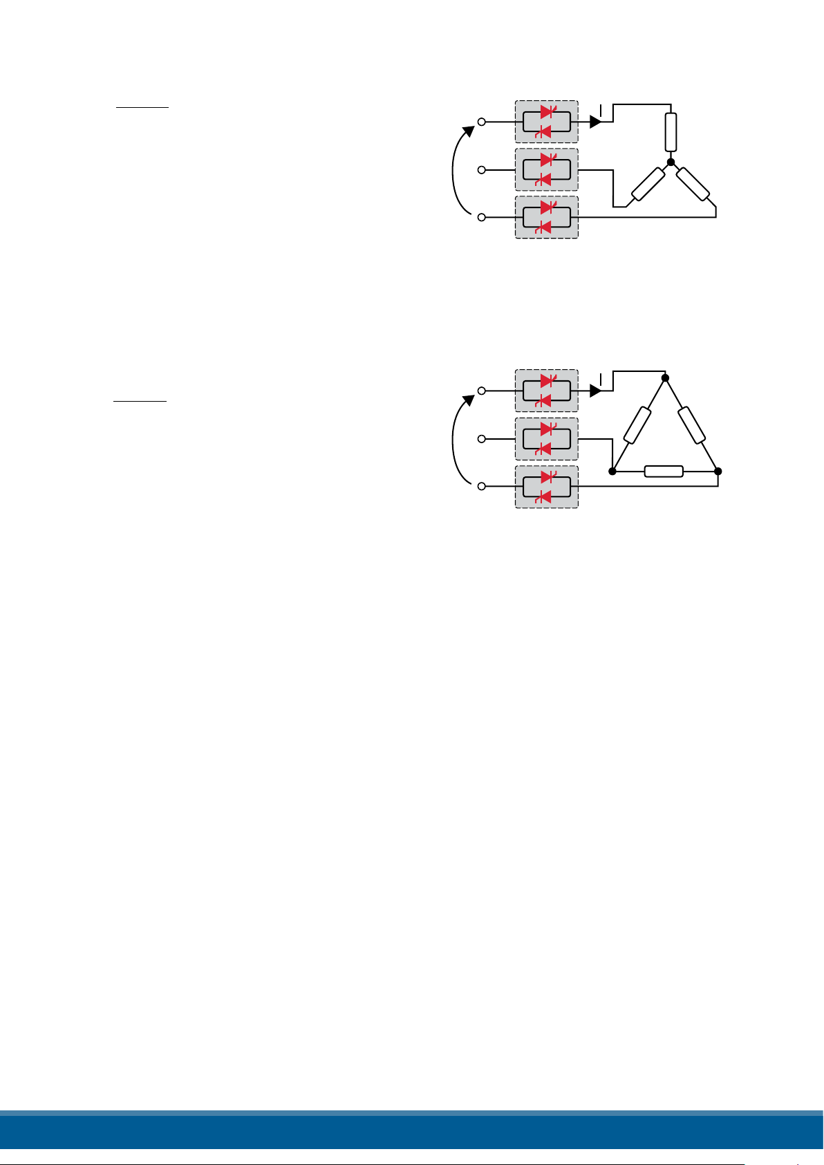
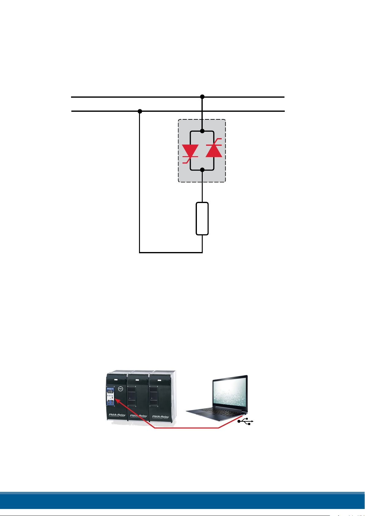
6. Basic Connections and sizing
Star wiring with resistive load (control on two phases with PMA-Relay C-3PH)
P
I=
1,73V
V
V = Nominal voltage of the load
I = Nominal current of the load
P = Nominal power of the load
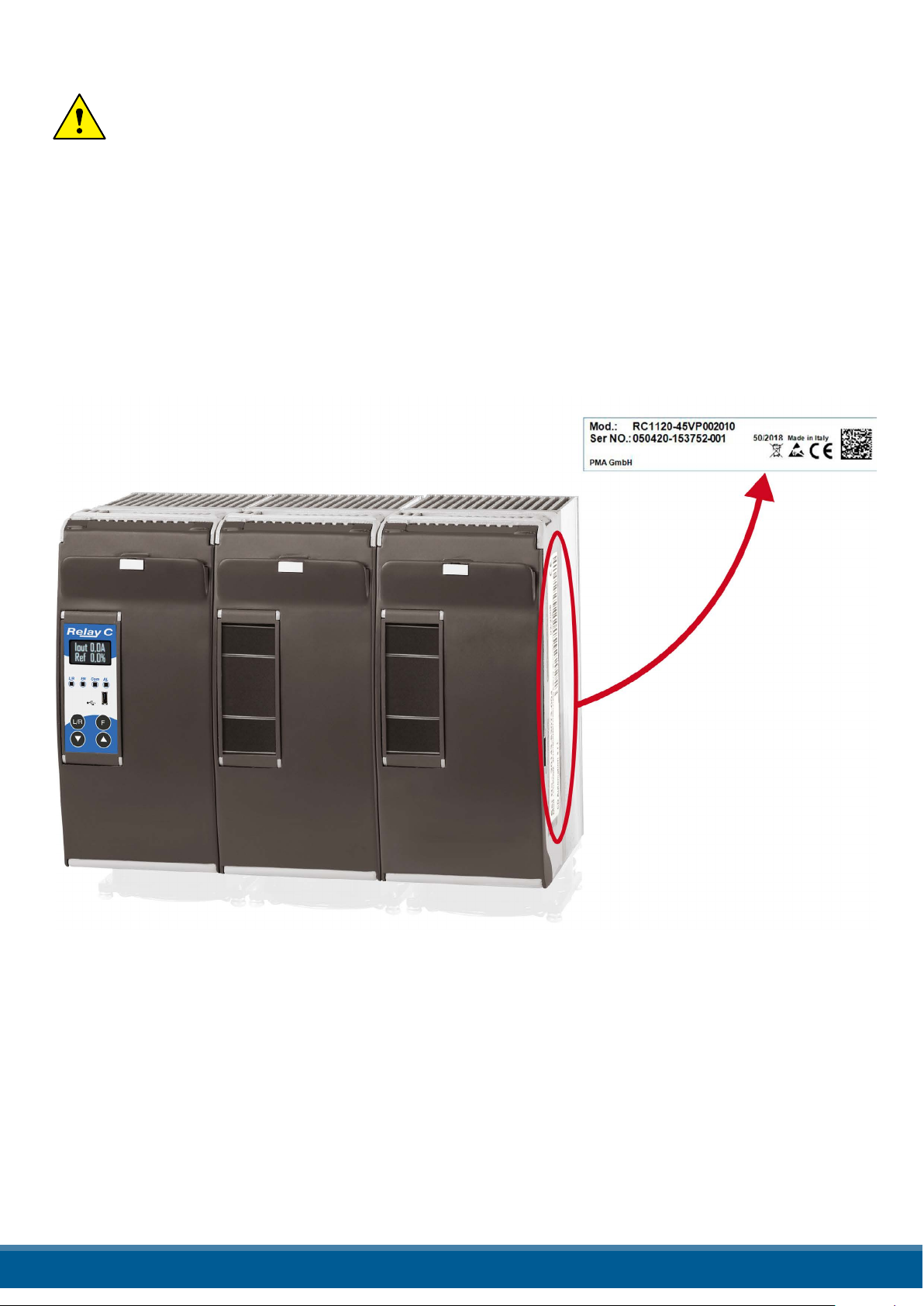
Delta wiring with resistive load (control on two phases with PMA-Relay C-3PH)
P
I=
1,73V
V
V = Nominal voltage of the load
I = Nominal current of the load
P = Nominal power of the load
www.west-cs.co.uk 13
Page 14
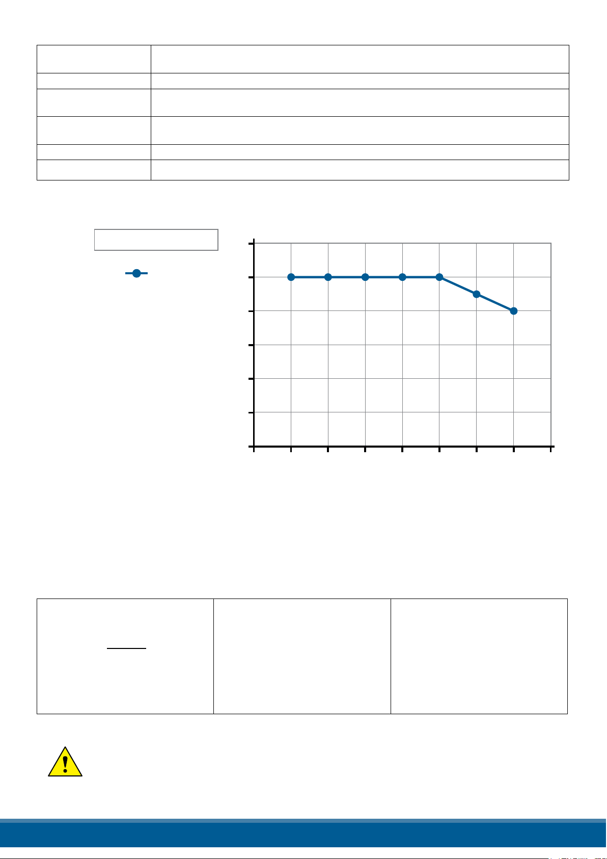
7. Identication
7.1. Identication of the unit
Caution: Before to install, make sure that the Thyristor unit have not damages. If the product has a
fault, please contact the dealer from which you purchased the product.
The identication’s label gives all the information regarding the factory settings of the Thyristor unit, this label is on the
unit, like represented in gure.
Verify that the product is the same thing as ordered.
www.west-cs.co.uk 14
Page 15

8. Order Code
RC3 x x x - x x x x x x x x x x
Current - Fuses
60 A - Fixed Fuses Included 0 6 0
90 A - Fixed Fuses Included 0 9 0
120 A - Fixed Fuses Included 1 2 0
150 A - Fixed Fuses Included 1 5 0
180 A - Fixed Fuses Included 1 8 0
210 A - Fixed Fuses Included 2 1 0
MAX VOLTAGE MAIN SUPPLY VOLTAGE 1*
480 V
600 V
690 V
MAIN SUPPLY VOLTAGE 1* Aux Voltage range
100/120 Vac
200/208/230/240 Vac
277 Vac
380/415/480 Vac
60 0 Vac
690 Vac 540 to 759 Vac
INPUT
SSR S
0:20 mA B
4:20 m A A
0:10 V (DC) V
10 kΩ potentiometer K
START OPTION
FIRING
Burst Firing (BF)
Phase Angle
Delayed Triggering No Soft Start D
Zero Crossing
CONTROL MODE
Open Loop O
Volt age U
Voltage Square U² Q
Current I
Current Square I² A
Power (U x I) W
OPTION
No Option 0
Energy totalizer 1
Datalogger 2
Datalogger + Energy totalizer 3
Heaterbreak Alarm (HB) 8
Heaterbreak Alarm (HB) + Energy totalizer 9
Heaterbreak Alarm (HB) + Datalogger A
Heaterbreak Alarm (HB) + Datalogger + Energy totalizer B
Current Limit G
Current Limit + Energy totalizer H
90 to 135 Vac
180 to 265 Vac
238 to 330 Vac
342 to 528 Vac
540 to 759 Vac
No soft start B
Linear Soft Starter J
No Soft Start P
Linear Soft Starter E
No soft start Z
Linear Soft Starter R
4
6
7
1
2
3
5
6
7
www.west-cs.co.uk 15
Page 16

RC3 x x x - x x x x x x x x x x
Current Limit + Datalogger I
Current Limit + Datalogger + Energy totalizer J
Current Limit + Heaterbreak Alarm (HB) O
Current Limit + Heaterbreak Alarm (HB) + Energy totalizer P
Current Limit + Heaterbreak Alarm (HB) + Datalogger Q
Current Limit + Heaterbreak Alarm (HB) + Datalogger + Energy totalizer R
FAN VOLTAGE
No fan < 90A 0
Fan 110Vac (≥ 90A) 1
Fan 230Vac (≥ 90A) – standard version 2
24Vdc (≥ 90A) - standard version 3
APPROVALS
CE 0
cULus L
LOAD T YPE
Normal Resistive Load with 3 Phase Star with neutral Connection 0
Normal Resistive Load with 3 Phase Delta Connection 1
IRSW Infrared Short wave with 3 Phase Star Connection with neutral 2
IRSW Infrared Short wave with 3 Phase Delta Connection 3
3 Phase Transformer coupled with normal resistance 4
3 Phase Transformer coupled with cold resistance 5
COMMUNICATION AND RETRANSMISSION
No.1 Modbus RTU No Retransmission 0
Retransmission 4:20 mA 1
Retransmission 0:10 V 2
No.2 Modbus RTU No Retransmission 3
Retransmission 4:20 mA 4
Retransmission 0:10 V 5
No.2 Probus DP + No. 1 Modbus RTU No Retransmission 6
Retransmission 4:20 mA 7
Retransmission 0:10 V 8
No.2 Pronet + No. 1 Modbus RTU No Retransmission 9
Retransmission 4:20 mA
Retransmission 0:10 V
No.2 Modbus TCP + No. 1 Modbus RTU No Retransmission
Retransmission 4:20 mA
Retransmission 0:10 V
*1 Since the supply voltage of the electronics is used for synchronization, it must be in phase with the load voltage.
A
B
C
D
E
8.1. Notes on the options:
8.1.1 I LIMIT (CURRENT LIMIT)
This option is used to keep the overcurrent inside setted limit. It’s necessary to drive primary transformers and cold
resistance. This option is not available on 30-35-40A units.
8.1.2. Heaterbreak Alarm (HB)
HB Alarm for partial or total load failure and Short Circuit on SCR (relay output).
8.1.3. Datalogger
This feature is important to see the historical data of parameter like Current, Voltage and Power and can be useful to
diagnose a fault.
8.1.4. Energy totalizer
This function totalizes the energy consumption of the load allowing the calculation of heat treatment.
www.west-cs.co.uk 16
Page 17

9. Technical specications
9.1. General features
Cover and Socket
material
Utilization Category AC-51 AC-55b
IP Code 20
Method of Connecting Load in Delta, Load in Star
Auxiliary voltage Order Code RC3_ _ _-_1 = line voltage 100/120V voltage range 90:135V (8 VA Max)
Relay output for Heater Break Alarm
(only with HB option)
PolymericV2
Order Code RC3_ _ _-_2 = line voltage 200/208/220/230/240V voltage range 180:265V
(8 VA Max)
Order Code RC3_ _ _-_3 = line voltage 277 voltage range 238:330V (8 VA Max)
Order Code RC3_ _ _-_5 = line voltage 380/400/415/440/480V voltage range 342:528V
(8 VA Max)
Order Code RC3_ _ _-_6 = line voltage 600V voltage range 540:759V (8 VA Max)
Order Code RC3_ _ _-_7 = line voltage 690V voltage range 540:759V (8 VA Max)
0.5A a 125VAC
9.2. Input features
Analog Input V: 0 to 10 Vdc impedance 15 kΩ
Analog Input I: 4 to 20 mA Impedance 100 Ω
Potentiometer 10 kΩ min.
Digital Input 4 to 30Vdc 5mA Max (ON ≥ 4Vdc OFF < 1Vdc)
9.3. Output features (power device)
Nominal
Current
(A) (V) (480V) (600V) (mAe) (10
60 24÷600 1200 1600 600 1900 15 10780 47÷70 290 3000
90 24÷600 1200 1600 600 1900 15 10780 47÷70 580 3000
120 24÷600 1200 1600 600 1900 15 14280 47÷70 598 3000
150 24÷600 1200 1600 300 5000 15 17500 47÷70 594 3000
180 24÷600 1200 1600 300 5000 15 30800 47÷70 740 3000
210 24÷600 1200 1600 300 5000 15 53900 47÷70 898 3000
Voltage
range
(Ue)
Repetitive peak
reverse voltage
(Uimp)
Latching
current
Max
peak
one cycle
msec.)
(A)
Leakage
current
(mAe) tp=
FUSE
I2T value
Suggested
A2s (at500V)
10msec
Frequency
range
(Hz) I =Inom
Thyristor
Power
loss
+ Fuse
(W)
Isolation
Voltage
(Ui)
(A)
9.4. Fan Specication (only from 90 to 210A)
Supply: 230V Standard Power 48W (16W for 3 Fan)
Supply: 115V Option Power 42W (14W for 3 Fan)
www.west-cs.co.uk 17
Page 18
9.5. Environmental installation conditions
Ambient temperature 0-40°C (32-104°F) at nominal current.
Over 40°C-104°F use the derating curve.
Storage temperature -25°C to 70°C -13°F to 158°F
Installation place Don’t install at direct sun light, where there are conductive dust, corrosive gas, vibration or
water and also in salty environmental.
Altitude Up to 1000 meter over sea level. For higher altitude reduce
the nominal current of 2% for each 100m over 1000m
Humidity From 5 to 95% without condense and ice
Pollution Level Up to 2nd Level ref. IEC 60947-1 6.1.3.2
9.6. Derating curve
l max = l nominal x K
Derating
1,2
1
0,8
0,6
K
0,4
0,2
1
1 1 1 1
0,9
0,8
For higher cabinet
temperature
contact the producer
of the unit
0
15 20 25 30 35 40 45 50 55
CABINET TEMPERATURE °C
9.7. Calculating ow capacity of the fan
All the thyristor units when are in conduction produces power loss that is dissipated inside cubicle in terms of
heating. Due to this fact the internal temperature of cubicle is higher than ambient temperature. To be cooled the
thyristor need of fresh air cooling and to do it is normally used a fan mounted on the front door or on the roof of the
cabinet.
Procedure to size Fan air mass ow (V): see power loss for each thyristor and fuse mounted indicated in the
manual related to the current (Output feature and Internal fuse Chapter).
V = f *
The formulas used are for information only and is not a substitute for a proper thermal rating
done by a qualied person.
Qv
tc-ta
Qv = total power losses (w)
(thyristor + fuse power loss)
ta = ambient temperature (°C)
tc = cabinet temperature (°C)
V = fan air mass ow (m³/h)
f = altitude coecient (see
table on right)
Altitude
0:100 meters f = 3.1 m³K/Wh
100:250 meters f = 3.2 m³K/Wh
250:500 meters f = 3.3 m³K/Wh
500:750 meters f = 3.4 m³K/Wh
www.west-cs.co.uk 18
Page 19
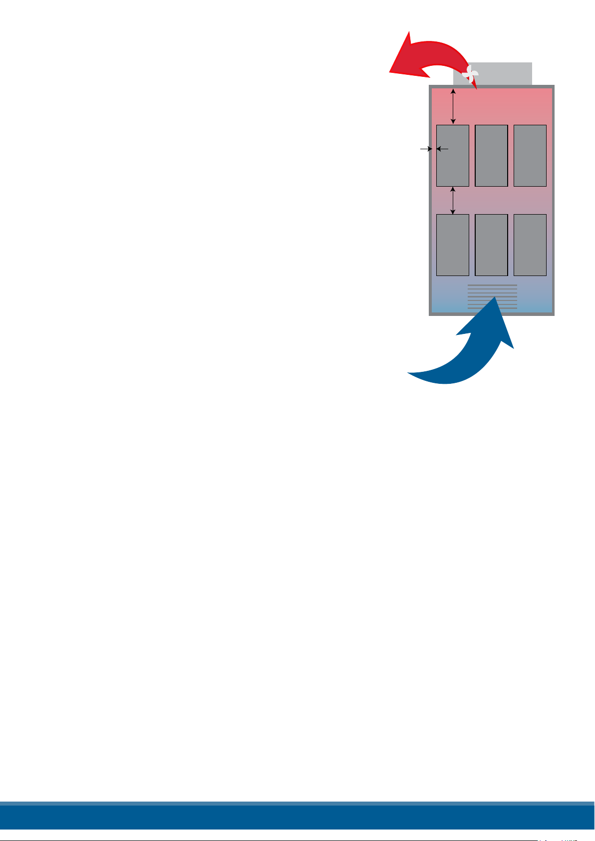
*30 cm
*20 cm
*2 cm
AIR FLOW IN (V)
AIR FLOW OUT (V)
FAN
in aspiration
Air Grid
10. Installation
Before to install, make sure that the Thyristor unit have not damages.
If the product has a fault, please contact the dealer from which you
purchased the product. Verify that the product is the same thing as
ordered.
The Thyristor unit must be always mounted in vertical position to improve air cooling on heat-sink. Maintain the minimum distances (*)
in vertical and in Horizontal as represented, this area must be free
from obstacle (wire, copper bar, plastic channel).
When more unit has mounted inside the cabinet maintain the air cir-
culation like represented in gure without obstacle for the air ow. Is
necessary to install a fan to have better air circulation as calculated
previously.
The V Air ow must be equal or more than the value calculated.
If the cabinet fan mounted by the customer have an air ow lower
than the correct value the warranty will decay.
www.west-cs.co.uk 19
Page 20
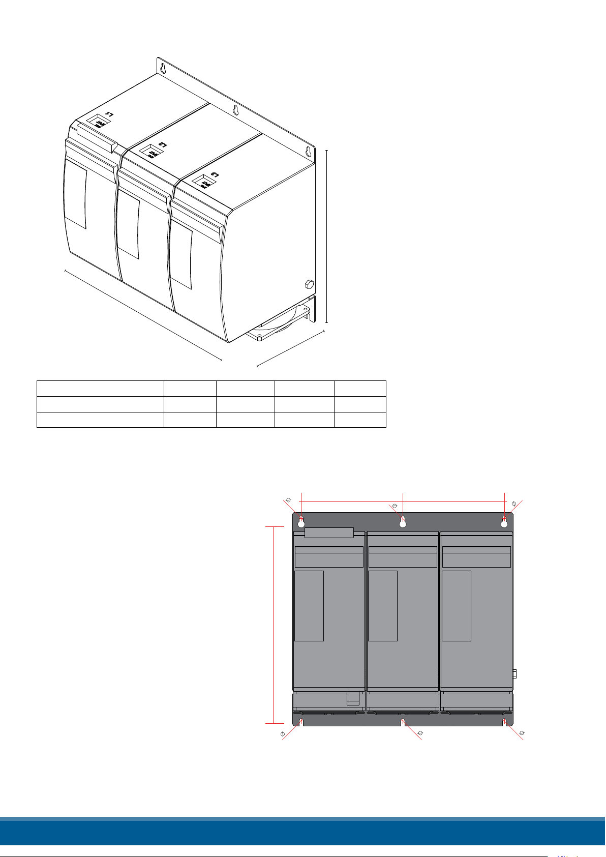
10.1. Dimensions and weight
W
D
H
5
5
5
5
5
5
129,5 129,5
H1
Type W H D Weight
3PH 60A no Fan 279 mm 269 mm 170 mm 10.2 kg
3PH 90-210A with Fan 279 mm 273 mm 170 mm 10.6 kg
10.2. Fixing holes
H1:
3PH (60A no Fan): 256
3PH (90-210A with Fan): 260
www.west-cs.co.uk 20
Page 21
11. Wiring instructions
The Thyristor unit could be susceptible to interferences lost by near equipments or by the power supply, for this
reason in accord to the fundamental practices rules is opportune take some precautions:
• The coil contactor, the relays and other inductive loads must be equipped with opportune RC lter.
• Use shielded bipolar cables for all the input and output signals.
• The signal cables must not be near and parallel to the power cables.
• Local regulations regarding electrical installation should be rigidly observed.
Use 75°C copper (CU) conductor only, wire ranges (AWG), wire terminal type (ZMVV), terminal tightening
torque in the table below.
Power cable torque (suggested)
Type Connector
Type
060
090
120
150
180
210
Cable dimensions of the Command Terminals 0.5 mm² (AWG 18)
Cable dimensions of the Earth (suggested) 16 mm² (AWG 6) up to 120A
25 mm² (AWG 4) up to 210A
Screw M6 70.8 (8.0)
Screw M8 141, 6 (16.0)
Torque Lb-in
(N - m)
Wire Range
mm² (AWG)
16(5)
25(3)
35(2)
50(0)
70(00)
90(000)
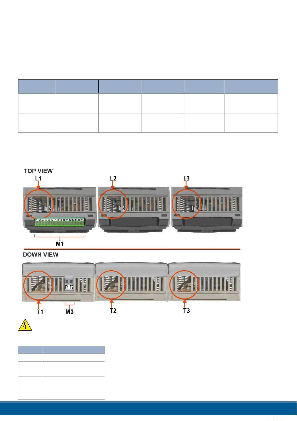
11.1. Terminal Positions
MAX Current
Terminals
150
250
Wire Terminals UL
Listed (ZMVV)
Fork/Spade Terminal
Copper Tube Crimp.
Lug
Fork/Spade Terminal
Copper Tube Crimp.
Lug
Warning: Before connecting or disconnecting the unit check that power and control cables
are isolated from voltage sources.
11.2. Power Terminals
Terminal Description
L1 Line Input Phase 1
T1 Load Output Phase 1
L2 Line Input Phase 2
T2 Load Output Phase 2
L3 Line Input Phase 3
T3 Load Output Phase 3
www.west-cs.co.uk 21
Page 22

11.3. Control Terminals
Warning: Before connecting or disconnecting the unit check that power and control cables
are isolated from voltage sources.
11.3.1. Terminal block M1
Terminal Description
1 0V GND
2 COM I - Common Digital Input
3 DI 2 – Enable Digital Input
4 DI 1 - Congurable Input
5 + Analog Input1 (0-10Vdc/4-20mA Analog Setpoint)
6 - Analog Input1 (0-10Vdc/4-20mA Analog Setpoint)
7 Output +10Vdc stabilized 1 mA MAX
8 + Analog Input2 (0-10Vdc/4-20mA Reference/ext.feed-back)
9 Slave Output
10 Retransmission Output
11 RS485 A
12 RS485 B
13 0V GND
14 C - Common contact alarm relay output
15 NO - Normally Open contact alarm relay output (Thermal or SC/HB/CL)
16 NC - Normally Close contact alarm relay output (Thermal or SC/HB/CL)
11.3.2. Terminal block M3
Terminal Description
F1 Fan supply (230V Standard – 115 Option - for DC Fan Option +24Vdc)
F2 Fan supply (230V Standard – 115 Option - for DC Fan Option -24Vdc)
www.west-cs.co.uk 22
Page 23
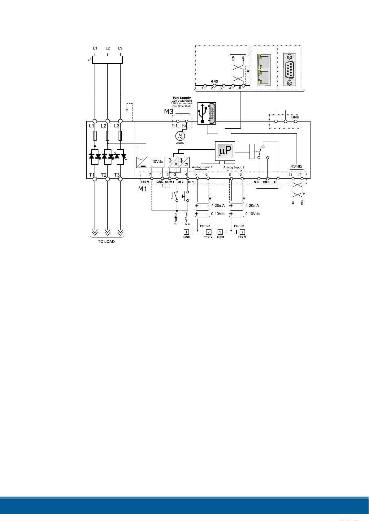
11.4. Schematic
Branch Circuit
Protection
M4
+24V
MICRO
USB 2.0
Second
Serial RS485
+
Option
Ethernet
-
M1
Function
Thermal
SC/HB
Profibus
OUT
RETRANS.
OUT
SLAVE
139 10
141615
2
Analog Inp.1
Analog SetPoint
Analog Inp.2
Reference
Ext.FeeDBack
NOTE:
*1 The user installation must be protecting by electromagnetic circuit breaker or by fuse isolator. The Fuse
must be branch circuit protection. For UL any listed UL branch circuit fuse would be acceptable as an
external fuse, following national electric code guide for resistive heating of 125% load current rating to protect
external wires.
*2 For SSR input connection follow next page schematic
www.west-cs.co.uk 23
Page 24

11.4.1 SSR Control Input Schematic
For SSR input follow the schematic below and congure Digital Input 1 as Fast enable.
Analog Input 1
M1
SSR
INPUT
www.west-cs.co.uk 24
Page 25
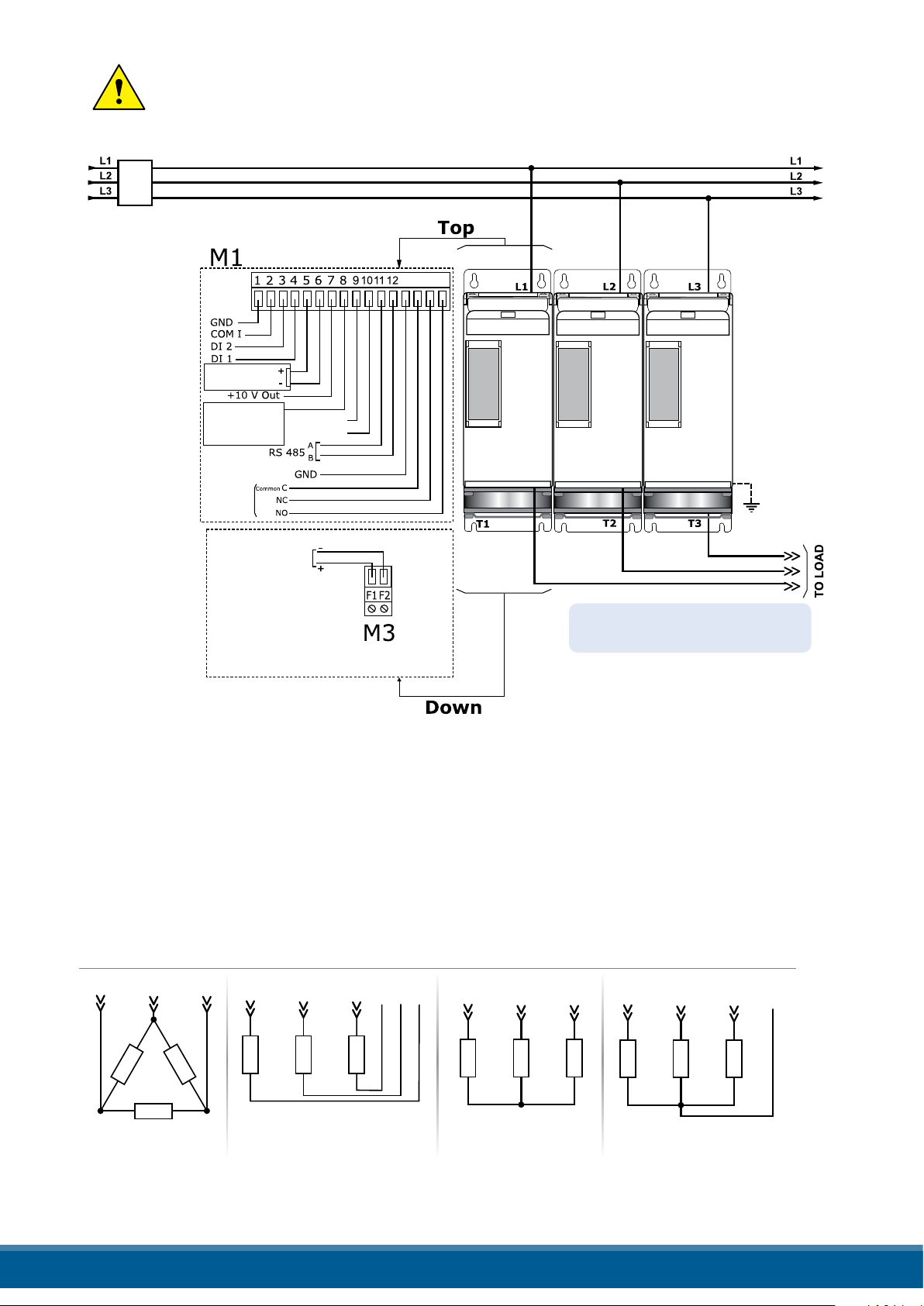
11.5 Connection Diagram for 3 phases
Load Type
Delta Star
T1 T2 T3
T1 T2 T3
Star + Neutral
T1 T2 T3 N
Open Delta
T1
L1 L3 L2
T2 T3
Relay
Thermal or
SC/HB
Analog Inp.2
0-10VDC /4-20mA
Reference
Ext.FeeDBack
Analog Inp.1
0-10VDC /4-20mA
ANALOG SET POINT
SLAVE OUT
RETRANS. OUT
1314 1516
Fan Supply
(only from 90 to 210A)
See order code for the Value
Caution: this procedure must be performed only by qualied persons.
Note: Aux Voltage and Load
Voltage must be synchronized
NOTE:
*1 A suitable device must ensure that the unit can be electrically isolated from the supply, this allows the qualied
people to work in safety.
www.west-cs.co.uk 25
Page 26

12. Control Panel
F
F
L/R
F
F
F
L/R
F
F
The Control Panel is placed on the front of the thyristor unit, on his display you can visualize the alarms, the
input and output signals and all the conguration parameters.
Relay C
Iout0.0A
SP 100%
L/R
Output Current RMS
F
Relay C
Iout0.0A
SP 100%
L/R EN Com ALL/R EN Com AL
L/R
Output Voltage (RMS)
F
On the home page the keys are used as follows:
Press.. To...
F
L/R
Function Scroll through the parameters on the home page
Local/Remote Switch between local and remote set point for power demand
Relay C
Pout0%
SP 100%
L/R EN Com AL
L/R
Output Power
(Average)
F
Relay C
Aux High
SP 100%
L/R EN Com AL
L/R
F
Alarms
Up Increment power demand set point when set to local
Down Decrement power demand set point when set to local
F
+
L/R
Press and hold for about two seconds to access the menus
To view the status parameters:
• Press Function once to advance from one parameter to the next
F
To set the set point locally:
• Press Local/Remote (Note: indicator 1 ashes steadily when set point is set locally)
• Use Down and/or Up to set the local set point.
L/R
www.west-cs.co.uk 26
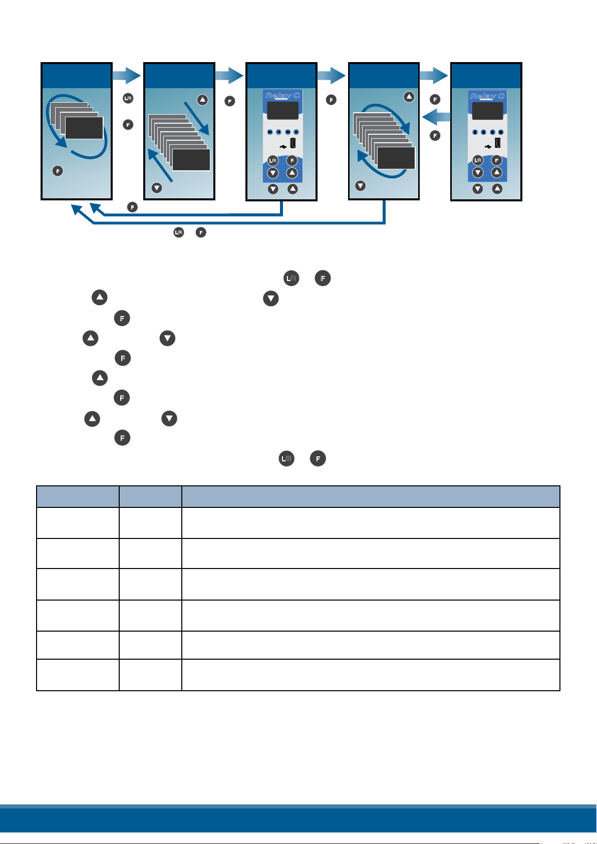
Page 27
12.1. Menu navigation
F
L/R
F
F
F
L/R
F
F
F
L/R
F
F
The menus are accessible using the control panel keypad and display.
HOME PAGE
Iout0.0A
Iout0.0A
SP 100%
Iout0.0A
SP 100%
Iout0.0A
SP 100%
SP 100%
F
L/R
+
F
(~2 sec)
F
Choose
Menu
Menu
Menu
Operator
Menu
Operator
Menu
Operator
Menu
Operator
Menu
Operator
Menu
Operator
Menu
Operator
Menu
Operator
Operator
(wrong password)
L/R
+
F
F
(~2 sec)
Enter
Password
Relay C
Relay C
Password
0
L/R EN Com AL
1 2 3 4
L/R
F
L/R
F
F
Choose
Parameter
Set Point
Set Point
100%
Set Point
100%
Set Point
100%
Set Point
100%
Set Point
100%
Set Point
100%
Set Point
100%
Set Point
100%
100%
Parameter
F
F
Edit
Relay C
Relay C
Set Point
100%
L/R EN Com AL
1 2 3 4
L/R
L/R
To access a menu and edit a setting:
1. Press and hold Local/Remote and Function together + until the upper display ashes Menu.
L/R
2. Press Up to choose the menu. (Press down if you overshoot the menu you want).
3. Press function to advance to the password prompt.
F
4. Use up and/or down to set the password (see the table).
5. Press function to enter the password and advance to the rst parameter of the menu.
F
F
F
F
6. Press Up to advance tot he next parameter and repeat to reach the desired parameter.
7. Press function to start editing the parameter. The parameter name ashes in the upper display.
F
8. Use Up and/or down to edit the parameter setting.
9. Press function to enter the new setting. The parameter name stops ashing.
10. Press and hold local/remote and function together + for about two seconds to exit the menus.
F
L/R
F
Menu Password Parameter used to..
Operator 0 View measured values and basic settings including current, voltage
and set point
Setup 2 Congure the power controller for the load
Adv Setup 10 Congure the operation and performance of the power controller in
the application
Hardware 5 Congure the functions of the analog and digital inputs and outputs,
and the retransmission parameters
Comm 3 Congure eld bus communicating parameters
Monitoring 0 View measured and calculated values and other read-only parame-
ters
www.west-cs.co.uk 27
Page 28

12.2. Control Panel Led
The four indicators on the control panel show the general state of the power controller.
Relay C
Aux High
SP 100%
L/R EN Com AL
1 Local/Remote Flashing Power output set locally or via
2 Enable On Output enabled
3 Communications Flashing Active communications
L/R
F
4 Alarm On Active alarm
12.3. Displayed alarms
Alarm or message Description
Heater Break Heater Break
communications
O Power output set remotely (via
analog input)
O Output disabled
O No alarm
Aux High Aux voltage too high
Aux Low Aux voltage too low
Bakeout Heater Bakeout function active
Watchdog Communication Watchdog error
Line Loss Line power not detected
I Limit Output limited by current limit feature (only single phase)
SD Card Error SD card error
Short Circuit Short Circuit on SCR
SCR Over Temp Thermal Switch over temperature
www.west-cs.co.uk 28
Page 29

12.4. Parameter list
This chapter describes the parameter on the menus accessed via the control panel and Congurator software.
To learn how to access the menus described below see “Menu navigation” chapter.
12.4.1 Operator Menu
This section describes each item on the operator menu. Use this menu to view the measured values and
basic settings of the power controller. The password to access this menu is 0.
Parameter
Name
Description Range Unit Modbus
Address
Par.
Typ e
SET POINT View the set point 0 to 100 % 15 Read
Only
V Output Indicates the average (RMS) voltage of all
phases
I Output Indicates the average (RMS) current of all
phases
0 to 1023 V 10 Read
Only
0 to 1023 V 11 Read
Only
Power Indicates the average (RMS) power output 0 to 100 % 12 Read
Only
V Input Indicates the average (RMS) voltage input 0 to
65535
Frequency Indicates frequency of the power input 0 to
655.35
V 47 Read
Only
Hz 9 Read
Only
Power Factor Indicates power factor of the output power 0 to 1000 102 Read
Only
Load Ω Indicates the resistance of the load 0 to
655.35
I Limit Indicates the maximum percent of the nomi-
0 to 100 % 17 Read
nal current that the power control allows. This
Ω 46 Read
Only
Only
parameter indicates RMS current by default.
When parameter 52 is set to 1, this parameter
indicates peak current
Out Scale Indicates the percentage by which the power
demand set point is scaled
Nominal V Indicates the user-set, nominal value for the
0 to
100.0
0 to 1023 V 37 Read
line voltage input
Nominal I Indicates the user-set, nominal load current 0 to
999.9
% 16 Read
Only
Only
A 38 Read
Only
www.west-cs.co.uk 29
Page 30

12.5 Setup Menu
This section describes each item on the setup menu. Use this menu to congure the power controller for the
load. The password to access this menu is 2.
Parameter
Name
Description Range Unit
Set the percentage by which the set point is scaled. For example, if a
Out Scale
0 to 10V analog input providing the set point is 5V and output scaling
is 80% then the eective set point is 40%
100
80
60
40
Parameter
Name
Scaled Set Point
20
0
0 20 40 60 80 100
Description Default Range Unit
Output Scaling = 100%
Output Scaling = 80%
Output Scaling = 40%
Input
Set the maximum percent of the nominal current that
I Limit
the power control allows. This parameter indicates RMS
current by default. When parameter 52 is set to 1, this
0%
parameter indicates peak current
Nominal V Set the nominal value for the line voltage input 220V
0 to
100.0
0 to
100.0
0 to
1023
Modbus
Address
% 16
Modbus
Address
% 17
V 37
Par.
Type
Read
Write
Par.
Type
Read
Only
Read
Write
Nominal I Set the nominal load current
Maximum
current
Set the duration of the soft start in increment of 50mSec.
Soft Start
The power controller ramps set to point changes over
the time set here. For more information see “Soft Start”
100
(5 sec)
page on this manual
Remote SP Choose the source for the remote set point 61
0 to
999.9
0 to 255
(0 to
12,75
sec)
A 38
23
Read
Write
Read
Write
Read
Write
Option Value
Analog Input 1 0
Analog Input 2 1
12.5.2 Advanced Setup Menu
This section describes each item on the advanced setup menu. Use this menu to congure the power switching, closed loop control of power and adjustable settings for data logging and heater bakeout. The password to access this
menu is 10.
Parameter Name Description Default Modbus Address Par. Type
Firing Choose the ring mode 3 18
Option Value
Zero Cross 1
Single Cycle 2
Burst Firing 3
Phase Angle 4
Burst ring start ramp 19
Read
Write
www.west-cs.co.uk 30
Page 31

Option cont. Value
Phase angle Soft Start 20
Burst Firing Delay Trigger 35
DEFAULT: Burst Firing 3
Parameter
Name
Min Cycles
Soft Start
Delay
Cycle time
Control
Mode
(Feed-back)
Description Default Range Unit
Set the minimum number of On cycles and o cycles for
burst ring
Set the duration of the soft start in increment of 50mSec. The
power controller ramps set to point changes over the time
set here. For more information see “Soft Start” page on this
manual
Set the ring delay degrees. Applies to burst ring with delay
trigger
Set the duration of one on-o cycle in increments of 50mSec.
Applies to zero crossing
Choose the feed-back type 1 19
Option Description Value
Voltage ² Voltage squared 0
None No feed-back 1
Current ² Current squared 2
Voltage Voltage 32
Current Current 64
Power Power 128
External External signal via analog input 2 256
DEFAULT: None 1
8 0 to 999.9 n° 20
100
(5 sec)
1 1 to 255 ° 23
60
(3 sec)
0 to 255
(0 to
12,75 sec)
0 to 255
0 to 12,75
sec)
Modbus
Address
23
24
Par.
Type
Read
Write
Read
Write
Read
Write
Read
Write
Read
Write
Parameter
Name
Prop band
power
Integral
power
Prop band
current
Integral
current
Htr Break
sensitivity
Htr Break
delay
Logging Enable or disable data logging on the internal SD card 0 139
Set the gain for the main loop. A smaller proportional band yields
a larger adjustment for a given deviation
Set how aggressively the integral part of the control algorithm
acts. A smaller settings yields a larger adjustment for a given
deviation over a given time
Set the gain for the main loop. A smaller proportional band yields
a larger adjustment for a given deviation
Set how aggressively the integral acts in the current loop. A
smaller settings
Set the threshold of resistance that activates the Heater
Break alarm. This setting is in percentage of the nominal load
resistance
Set a delay between when the resistance drops below the value set
for a heater break sensitivity and when the heater break alarm is
indicated. This set increments of 50mSec
Description Default Range Unit
10%
50
10%
50
100%
50 (2,5
sec)
0 to
255
0 to
255
0 to
255
0 to
255
0 to
100.0
0 to
255
(0 to
12,75
sec)
Modbus
Address
% 26
% 63
% 29
27
64
28
Par.
Type
Read
Write
Read
Write
Read
Write
Read
Write
Read
Write
Read
Write
Read
Write
www.west-cs.co.uk 31
Page 32

Option Value
O 0
On 1
DEFAULT: O 0
Parameter Name Description Default Range Unit
Logging interval Set how often data is logged 5 sec 0 to 255 sec 70
Heater Bakeout Enable or disable the heater bakeout feature 0 140
Option Value
O 0
On 1
DEFAULT: O 0
Modbus
Address
Par.
Type
Read
Write
Read
Write
12.5.3 Hardware Menu
This section describes each item on the hardware menu. Use this menu to congure how the inputs and outputs
are used in the application. The password to access this menu is 5.
Parameter Name Description Default
Analog In 1
Choose the type of signal to be measured by analog input 1
Option Description Value
0-10V / 10k Pot 0 to 10 Vdc or 10,000Ω 1
4-20mA 4 to 20 mAdc 2
0-20mA 0 to 20 mAdc 3
DEFAULT: 0-10V / 10k Pot 1
1 44
Modbus
Address
Par.
Type
Read
Write
Parameter Name Description Default
Analog In 2
Parameter Name Description Default
Analog In 2
Function
Choose the type of signal to be measured by analog input 2
Option Description Value
0-10V / 10k Pot 0 to 10 Vdc or 10,000Ω 1
4-20mA 4 to 20 mAdc 2
0-20mA 0 to 20 mAdc 3
DEFAULT: 0-10V / 10k Pot 1
Choose how the signal measured by analog input 2
is used
Option Description Value
I Limit Current Limit Set point 0
Feed-back External feed-back 1
Set Point Power Demand set point 2
DEFAULT: I Limit 0
1 105
0 or 1 116
Modbus
Address
Modbus
Address
Par.
Type
Read
Write
Par.
Type
Read
Write
Parameter
Name
Digital In 1
Function
Description Default
Choose how the signal detected by digital input 1 is used 0 32
Modbus
Address
Par.
Type
Read
Write
www.west-cs.co.uk 32
Page 33

Option Description Value
Enable Enable power output 0
Voltage Feed-back Use voltage feed-back when on 2
Local / Remote Local when on / Remote when o 3
Phase Angle Use phase angle ring when on 4
Set point Analog In 1/2 Select remote set point source: analog input 1 when o or analog
input 2 when on
Logging Enable logging 6
Heater Bakeout Enable heater bakeout 7
FastEn Fast Enable, power on up to 10msec (only with phase angle ring) 8
DEFAULT: Voltage Feed-back 2
5
Parameter Name Description Default
Digital In 2
Function
Option Description Value
Enable Enable power output 0
Voltage Feed-back Use voltage feed-back when on 2
Local / Remote Local when on / Remote when o 3
Phase Angle Use phase angle ring when on 4
Set point Analog In 1/2 Select remote set point source: analog input 1 when o or analog input 2 when on 5
Logging Enable logging 6
Heater Break Enable heater break 7
FastEn Fast Enable, power on up to 10msec (only with phase angle ring) 8
DEFAULT: Enable 0
Parameter
Name
Choose for which conditions the digital output indicates alarm. The output
always indicate an alarm when the heat sink is over temperature. The digital
Alarm
Function
output is energized for normal operating condition and de-energized when
the power controller is o or when there is an alarm.
Note!: The power controller monitors for heater break or short circuit
condition only when included in the option selected for Alarm Output Function
Choose how the signal detected by digital input 2 is used 33
Description Default
Modbus
Address
1 34
Par.
Type
Read
Write
Modbus
Address
Par.
Type
Read
Write
Option Description Value
None SCR is over temperature only 0
Heater Break Heater Break or SCR is over temperature 1
Short Circuit Short circuit or SCR is over temperature 2
Current Limit Current Limit or SCR is over temperature 4
HB / SC Heater Break or Short circuit 3
HB / IL Heater Break or Current Limit 5
SC / IL Short circuit or Current Limit 6
HB / SC / IL Heater Break, Short circuit or Current Limit 7
Communication watchdog error 16
Communication watchdog error or Heater Break 17
Communication watchdog error or Short circuit 18
These option may be set
via communication only
DEFAULT: Heater Break 1
Communication watchdog error, Heater Break or Short circuit 19
Communication watchdog error or Current Limit 20
Communication watchdog error, Heater Break or Current Limit 21
Communication watchdog error, Short circuit or Current Limit 22
Communication watchdog error, Heater Break, Short circuit or Current Limit 23
www.west-cs.co.uk 33
Page 34

Parameter Name Description Default
Modbus
Address
Par.
Type
I Limit Local /
Remote
Parameter Name Description Default
Retransmit
Choose how the current limit is set 0 14,bit 4
Option Description Value
Local Set point set via keypad or commu-
nication
Analog In2 Set point set via analog input 1
DEFAULT:
Local
Choose wich parameter is retransmitted by the
analog output
Option Description Value
None Do not retransmit value 0
Set Point Set point 15
V Output RMS voltage output 10
I Output RMS current output 11
Power Average output power 12
DEFAULT: Power 12
RMS voltage output 0
12 68
0
Modbus
Address
Read
Write
Par.
Type
Read
Write
Parameter Name Description Default Range Unit
Set the value of retransmitted
Retransmit Sale
Retransmit
Set Point 100
xV where x is
V Output
I Output
Power 100
Parameter Name Description Default
the Nominal Line
Voltage
xA where x is
the Nominal Line
Current
parameter to be represented by the
full scale of the analog output.
See the table below
Recommended
Retransmission
Scaling
Resulting Signal
(4 to 20 mADC)
4mADC = 0%
20mADC = 100%
4mADC = 0V
20mADC = xV
4mADC = 0A
20mADC = xA
4mADC = 0%
20mADC = 100%
0 0 to 9999 124
Resulting Signal
(0 to 20 mADC)
0mADC = 0%
20mADC = 100%
0mADC = 0V
20mADC = xV
0mADC = 0A
20mADC = xA
0mADC = 0%
20mADC = 100%
Resulting Signal
(0 to 10 VDC)
0VDC = 0%
10VDC = 100%
0VDC = 0V
10VDC = xV
0VDC = 0A
10VDC = xA
0VDC = 0%
10VDC = 100%
Modbus
Address
Modbus
Address
Par.
Type
Read
Write
Max Value
100.0
999.9
999.9
100
Par.
Type
Retransmit Type Choose type of signal for the retransmission output 1 69
Option Value
0-10V 1
4-20mA 0
0-20mA 2
DEFAULT: 0-10V 1
Read
Write
www.west-cs.co.uk 34
Page 35

Parameter Name Description Default
Modbus
Address
Par.
Type
Startup Display
Choose wich parameter is displayed on the home
page at power-up
Option Value
Current 0
Voltage 1
Power 2
DEFAULT: Voltage 1
1 60
Read
Write
12.5.4. Communication Menu
This section describes each item on the communication menu. Use this menu to congure the communication options. The password to access this menu is 3.
Parameter Name Description Default
Port 1 Baud Choose the baud rate for the primary serial port 2 30
Option Value
9600 0
19200 1
38400 2
115200 3
DEFAULT: 38400 2
Modbus
Address
Par.
Type
Read
Write
Parameter Name Description Default Range Unit
Port 1 Address
Port 2 Baud
Parameter Name Description Default
Watchdog
Set the address for the primary serial
port
Choose the baud rate for the primary
serial port
Option Value
9600 0
19200 1
38400 2
115200 3
DEFAULT: 38400 2
Enable or disable the watchdog on the primary
serial port
Option Value
O 0
On 1
DEFAULT: O 0
1 0 to 255 31
2 45
Modbus
Address
0 142
Modbus
Address
Par.
Type
Read
Write
Read
Write
Par.
Type
Read
Write
www.west-cs.co.uk 35
Page 36

Parameter Name Description Default Range Unit
Watchdog Reset
Time
Wi-Fi Address
Ethernet Address
Ethernet Subnet
Ethernet Gateway
Host Name
Port 2 Address
Set the amount of time to wait for a
message before triggering the watchdog
error
Indicate the IP address of the WiFi
connection in the power controller
Indicate the IP address of the power
controller with the Modbus TCP or
Pronet option
Indicate the subnet mask of the the
power controller with the Modbus TCP or
Pronet option
Indicate the gateway address of the the
power controller with the Modbus TCP or
Pronet option
Indicate the WiFi hotspot name also
known as the Service Set IDentiner
(SSID). Two (one byte) character per
register, 16 Character total
Set the address for the secondary serial
port or the Probus Address
5 0 to 255 Sec 143
0 to 255
0 to 255
0 to 255
0 to 255
0 to 65535
0 0 to 1024 122
Modbus
Address
94-95
96-97
71-72
73-74
75-76
77-78
79-80
81-82
83-84
85-86
87-88
89-90
Par.
Type
Read
Write
Read
Only
Read
Only
Read
Only
Read
Only
Read
Only
Read
Write
Port 2
Parameter Name Description Default
Wi-Fi Enable or disable WiFi communication 0 120
Indicates the type of secondary
communication port
Option Description Value
Disabled No secondary communication port 0
Ethernet Modbus TCP or ProNet 1
RS-485 RS-485 2
Option Value
O 0
On 1
DEFAULT: O 0
119
Modbus
Address
Read
Write
Par.
Type
Read
Write
12.5.5 Monitoring Menu
This section describes each item on the monitoring menu. Use this menu to view the states of digital input, values
of analog input and information about the power controller such as serial number and software version. The
password to access this menu is 0.
Parameter Name Description
Digital In 1 Indicate the state of the signal to digital input 1 13 bit8
Modbus
Address
Par.
Type
Read
Only
www.west-cs.co.uk 36
Page 37

Option Value
O 0
On 1
Parameter Name Description
Digital In 2 Indicate the state of the signal to digital input 2 13 bit9
Option Value
O 0
On 1
Parameter Name Description
Indicate whether or not the power controller is enabled.
Enable
The enable signal must be on for the unit to output power
to the load
Option Value
O 0
On 1
Modbus
Address
Modbus
Address
14 bit2
Par.
Type
Read
Only
Par.
Type
Read
Only
Parameter Name Description
Set Point Source
Parameter Name Description Range Unit
Analog In 1
Analog In 2
Version Indicates the software version number (x.xx.x) 0 to 65535 48
Release
Unit Type Indicates the type of power controller 36
Indicate whether the power controller is local or remote set
point mode
Option Description Value
Remote Set Point via analog input 0
Local Set Point via keypad or communication 1
Indicates the percent of full scale measured
by analog input 1
Indicates the percent of full scale measured
by analog input 2
Indicates the software release date year and
week (yyww)
0 to 100.0 % 138
0 to 100.0 % 137
0 to 65535 49
Modbus
Address
14 bit1
Modbus
Address
Par.
Type
Read
Only
Par.
Type
Read
Only
Read
Only
Read
Only
Read
Only
Read
Only
www.west-cs.co.uk 37
Page 38

Option Description Value
1 Leg Single Phase 7
2 Leg Two Leg, three phase 8
3 Leg Three Leg, three phase 9
3 Leg PA Three Leg, three phase with phase angle capability 9999
Parameter Name Description Range Unit
Max Voltage
Max Current
Aux Voltage Indicates the measured line voltage 0 to 1023 V 43
Serial Number
SCR Temperature
Indicates the maximum voltage rating of the
power controller
Indicates the maximum current capacity of the
power controller
Indicates the serial number of the power
controller
Indicates whether the SCR is below or above
the factory-set trip point
Option Description Value
Disabled No sensor present / temperature below limit 0
Over Temp Over temperature 130
0 to 1023 V 41
0 to 9999 A 62
0 to 9999
Modbus
Address
149-150
151-152
127
Par.
Type
Read
Only
Read
Only
Read
Only
Read
Only
Read
Only
www.west-cs.co.uk 38
Page 39
13. Using the Congurator
Congurator software can be used like an alternative of the power controller’s keypad and set the advanced
features not available via the power controller’s onboard user interface.
Here will explain how use it.
13.1 Typical Uses
The software may be used during commissioning to:
• set internal parameter do determine how the power controller operates and performs;
• save and restore a setup, copy or clone one power controller to another;
• on a day-to-day basis to monitor operation and power usage;
• to examine performance in more detail to determine if any corrective actions are needed.
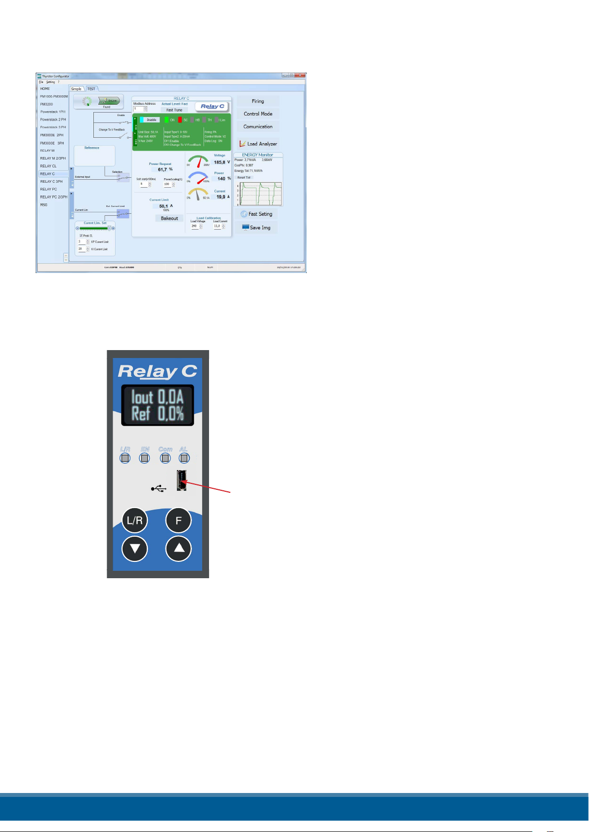
13.2 Communicating with Power Controllers
When commissioning the power controller, may be useful to connect via the USB port located below the
control panel’s display a computer, is so possible congure and examine the settings of controller.
The controller’s electronics is powered vis USB cable, so is possible inspect it before applying power.
NOTE! the power of the USB port is limited and not designed to power industrial cards, so it manages
to feed only the essential parts of the electronics. For complete control, you need to power up the
auxiliaries of the power controller.
13.3 Recipes
A recipe is a le that store the settings of power controller internal parameter.
Is used to save a power controller conguration or restore an existing conguration in a power controller.
13.3.1 Upload a recipe
A recipe is created using upload function Congurator software and saving it as a le on the computer.
13.3.2 Download a recipe
An existing recipe can be download to a power controller using download function in Congurator software
13.4 How To
Here it is described step-by-step the procedures for common task.
13.4.1 Install and communication with the power controller
Procedure to install the Congurator:
1) Locate the installer:
- On https://www.west-cs.com
link is possible Download it
2) Double-click on the installer program to start installation.
3) Follow the on-screen instructions.
www.west-cs.co.uk 39
Page 40
Procedure to communicate with a power controller:
1) if used direct USB connection:
- Connect the USB cable between the computer
and the micro USB connector on the power
controller’s keypad
- if necessary, Wait for the USB driver to install.
2) if used RS-485 connection connect the power
controller terminal to computer RS485 port. Usually
the standard pc do not have a RS485 port so a
USB-to-485 converter is required.
Note: for connection detail See “Communication
Connections” paragraph.
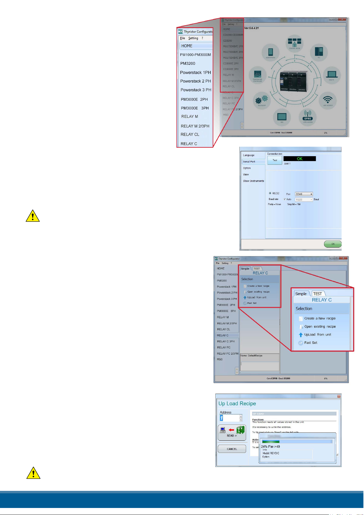
3) Launch the Congurator software an select
- Relay C: for single phase
- Relay C: 3PH for 3 phase power controller
4) Choose Serial Port From the Setting -> Serial Port
menu
5) In value Port, select the connected COM port to the power
controller (see the note below)
6) To verify communications, click Test
7) Click OK
NOTE! to determine which port is connected to the power
controller, you can:
• In the Windows¨ Device Manager under Ports (COM & LPT), looking
for the COM port named “LPC USB VCOM Port (COMx)” where x is
the port number
• In the congurator software:
- open the software without connect the unit and see the
available com port on con port window setting,
- close the com setting window,
- connect the USB cable to the power controller (wait for the
USB driver to install if necessary), - open the com setting
window and see the added com number and select it.
13.5 Using the Congurator
After software has been installed, communication has been
set up and model type selected, is possible operate with
power controller.
13.5.1 To view or save a power controller’s settings using “Simple” view section:
1) Click Simple, if not already on the simple view
2) Click Upload from unit
3) Set the address, if necessary
4) Click READ->
5) Wait for the software to read the parameter settings
6) Click OK
7) If need save the settings in a recipe le:
- Click Save
- Name the recipe
- Click Save button
NOTE! In the simple view the change are not “live”, so
to take eect the change in simply section is necessary
download it with download procedure.
www.west-cs.co.uk 40
Page 41
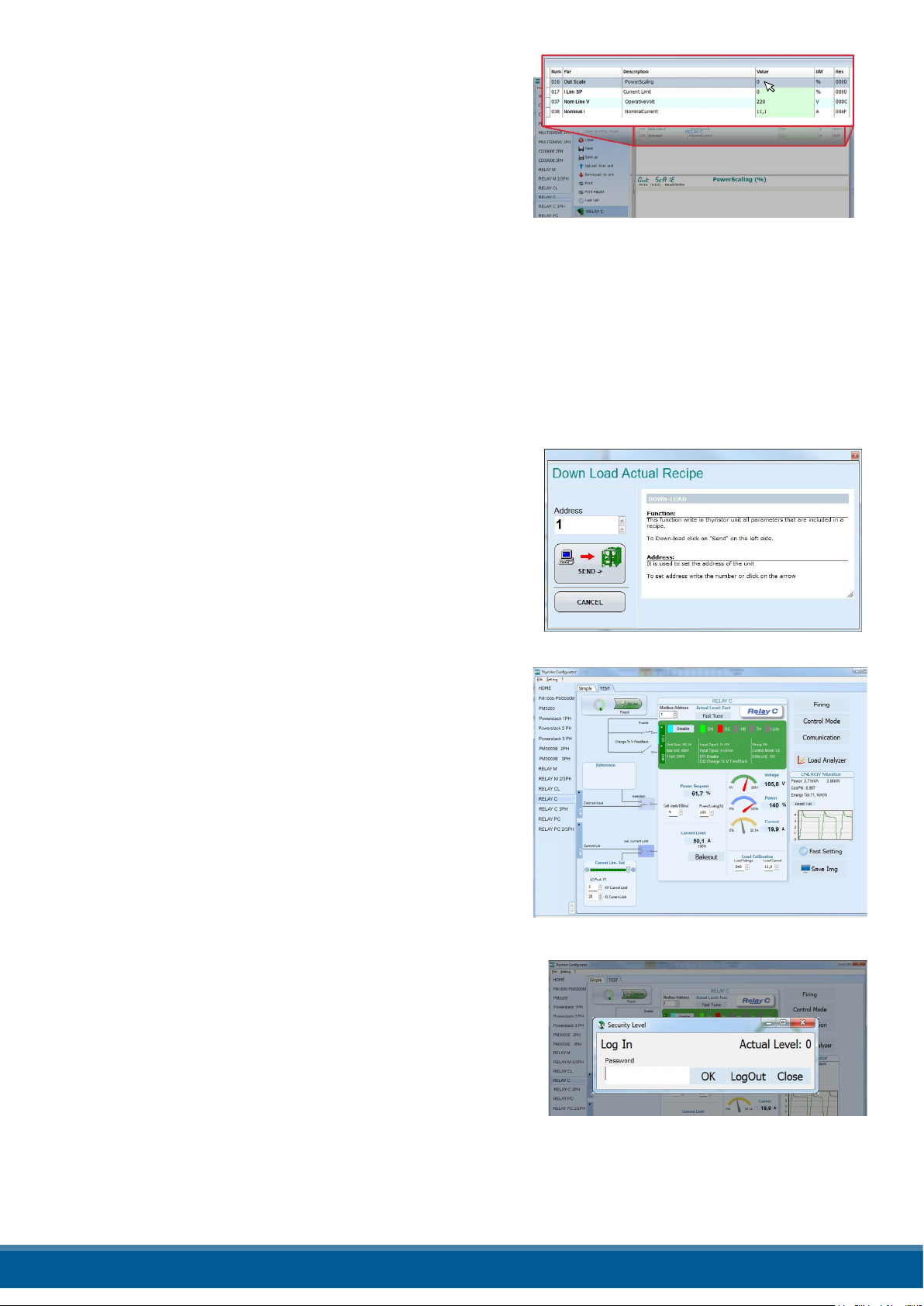
13.5.2 To edit a setting in a recipe:
1) Click Simple, if not already on the simple view
2) Click Open existing recipe
3) Locate and select the recipe le and click Open
4) Click OK
5) Click the menu with the setting you want to change
- SETUP
- ADVANCED SETUP
- HARDWARE
- COMMUNICATIONS
6) Select the value you want to change
7) Edit the value with the increment and decrement buttons in the eld or type the new value and press the
Enter key
8) Repeat steps 5 to 7 for all the changes you want to make
9) To save the settings in a recipe le:
- Click Save
- Name the recipe
- Click Save button
13.5.3 To download a recipe le into a power controller:
1) Click Simple, if not already on the Simple view
2) Click Open existing recipe
3) Locate and select the recipe le and click Open
4) Click OK
5) Click Download to unit
6) Set the address, if necessary
7) Click SEND->
8) Wait for the software to write the parameter settings
9) Click OK
13.5.4 To monitor a power controller with the Test view:
1) Click Test , if not already on the test view
2) Click Online
13.5.5 To log in on the test view to change the digital input and analog input functions:
1) Click the Access Level value (zero when logged out)
2) Type the password: 1111
3) Click OK
13.5.6 To log out the test view:
1) Click the Access Level value.
2) Click Log out.
3) Click OK.
www.west-cs.co.uk 41
Page 42

13.5.7 To view data on the scope:
1) Click Test , if not already on the test view
2) Click Online
3) Click Load Analyzer
4) For each of up to three channels (Ch 1 to Ch 3):
- With PV1 choose the value to monitor
- Select Show
- Click the colour swatch to change the colour
- Click the button to turn the channel on.
13.5.8 To reset the power totals:
1) Click Test , if not already on the test view
2) Click Online
3) Click Reset Totals
4) Click Yes
13.5.9 Setting Up and Using Data Logging
To set up data logging:
1) Click Test , if not already on the test view
2) Click Online
3) Click Load Analyzer
4) On the Load Analyzer view click Data Log
5) In the Data Log window ensure the slider is set to Log Enabled
6) Click Set Time
7) If necessary Set the date and time and close the date/time window
8) Set Log Time to the number of seconds between records
9) Click Connect
10) Click Cong
11) Click Load Conguration to view the current list of logged parameters
12) For up to ten parameters to log:
-Click + to add a parameter to the list
-In a row in the list either: Type a parameter’s Modbus address in the Par eld
OR
-Select the parameter from the drop down list in the Name eld
13) Click Write Conguration to send the parameter list to the controller
14) Click Close
15) Click Disconnect
16) Close the Data Log window
www.west-cs.co.uk 42
Page 43
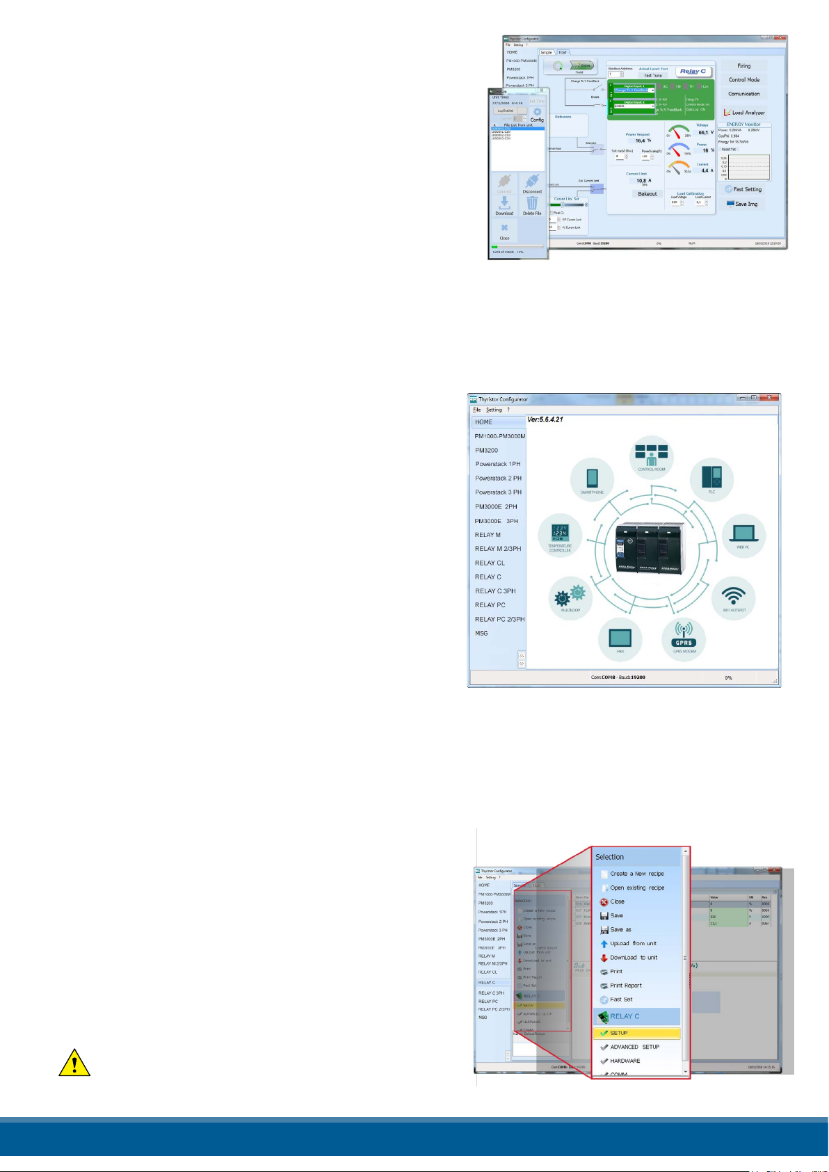
13.5.10 To retrieve a data log le from the power controller:
1) Click Test , if not already on the test view
2) Click Online
3) Click Load Analyzer
4) Click Connect
5) Select a le from the list
6) Click Download
7) Select a location and click Save
8) Wait for the le to download. This can take up to ten minutes
for the largest le
9) To delete the log le from the controller memory, if desired,
click Delete File
10) Click Disconnect
11) Close the Data Log window
12) Close the Load Analyzer window
13.6 Software General information
Here it is described the Congurator Software and how use it.
13.6.1 Program Window
Main Menu
Access these menus.
File menu
Exit: close the program
Setting menu
Language: open language Settings dialog box
Serial Port: open Serial Port dialog box
Option: open General Option dialog box
? (Help) menu
Message Log: open a serial communication message view
About: displays the About dialog with the program name and
version and contact information
Instruments selector
Select the right instrument to use:
HOME: the default view
Relay C: open the Simple and Test views for a single-phase power controller
Relay C 3PH: access the Simple and Test views for a three-phase power controller
MSG: opens a serial communication message view
Status Bar
Indicates information such as time and date, communications port and baud rate.
13.6.2 Simple Section
This section is used to create, save, upload and download
recipes of parameters settings. Can be used also to see the
settings in a controller.
Simple page is the default page when select the model using
the Model Button, but If not selected is possible access it
clicking the Simple tab below the main menu.
NOTE! This section is not “OnLine” so the parameter
values are not updated continuously. They are read only
when you upload them from the power controller.
www.west-cs.co.uk 43
Page 44

To manage recipe click on:
Create a New recipe: create a recipe le with the standard
default settings
Open existing recipe: open an existing recipe le
Upload from unit: create a new recipe with the value
uploaded from a connected power controller
Close: close the current recipe
Save: save the recipe in a le
Save as: save a copy of the recipe in a le
Download to unit: send the current recipe parameters in the connected power
controller
Print: print the recipe (see sample at right)
Print report: print the recipe (see sample at right)
To edit the actual recipe values click a parameter menu name:
SETUP
ADVANCED SETUP
HARDWARE
COMMUNICATIONS
And after click on the value and modify it.
NOTE!
Changes to the values here aect the open recipe only.
To apply these changes to the power controller settings,
download them to the power controller using the
Download to unit option.
13.6.3 Test Section
This section is used to monitor and adjust the operation
of the power controller in real time using RS485 or USB
communication port.
After select the model, is possible access to this section
clicking the “TEST” tab below the main menu
Operating on TEST Section:
Online button: is the button to start or stop communication
updates with the power controller
After communication start a green communication
status indicator sweeps clockwise when the software
is communicating right with a power controller, is the
connection link is broken the color will become red
Address: value used to set the power controller address
Access Level: click the value to log in or out. Default Password address is “1111”.
To congure and monitor the digital inputs:
Digital input states and functions:
show whether each input detects an open or closed circuit and
the function the input performs
Digital Input States and Function Selectors:
set the function for each digital input. Click DI1 or DI2 to expand
the options.
www.west-cs.co.uk 44
Page 45

Status and Setup Indicators:
Digital input status: light on when the input is a a closed circuit
Enable indicator: light on when the power controller is enabled
Enable/Disable button: click on to enable the power
controller if a digital input is not congured for this function
ON indicator: light on when there is demand for the output
to be on
SC indicator: light on when there is a shorted SCR alarm active
HB indicator: light on when there is a heater break alarm active
TH indicator: light on when the heat sink over temperature
alarm is active
I Lim indicator: light on when the load current exceeds the
current limit setting
Unit Size: Indicate the maximum rated current of the power controller
Max Volt: indicate the maximum rated voltage for the power controller
V Aux: indicate the voltage the auxiliary input is set to use for powering the electronics
Input Type 1: indicate the signal analog input 1’s type
Input Type 2: indicate the signal analog input 2’s type
DI1: indicate digital input 1’s function
DI2: indicate digital input 2’s function
Firing: indicate the ring type the power controller is set to use
Feedback: indicate the feedback type the power controller is set to use
Data Log: indicate the Data Log status
Buttons setup options:
Firing: view and set the ring type and the associated parameters
Feedback: view and set feedback type
Communication: view and set communication options for ports,
protocols and eldbus
Congure and monitor the analog inputs:
Analog Input 1: click Ai 1 to view the signal type
Input Local/Remote selection button: click to toggle between using the
signal received at analog input 1 (remote) or the slider (local) to set the set
point.
Reference: drag the slider, click the increment (+) or decrement (-) buttons
or click one of the three percentages (0%, 50% or 100%) to set the set point
when the set point source is set to local.
Analog Input 2: click Ai 2 to view the signal type and function
To congure and monitor the power controller:
Power Request: show the set point signal from analog input 1.
the value is a percent of full scale or can be set with the reference slider
Soft Start Time: show the time over which set point changes are ramped
Output Scaling: show the scaling applied to the set point signal before it is used by the control loop
Voltage indicator: show RMS load voltage
Power indicator: show RMS load power
Current indicator: show the RMS load current
Current Limit Set: indicates the current limit set point
Bakeout button: click to view and set the heater bake out feature options
Load Calibration: set and view the nominal line voltage and nominal
load current settings for the application.
www.west-cs.co.uk 45
Page 46

NOTE! The Load Calibration settings, Load Voltage and
Load Current dene 100% power for the load.
Energy Monitor: indicates power, power factor and energy
usage over time which may be reset with the Reset Tot button.
Data Log: If present is used to congure the data logging
feature data logs.
Save Image: click to save a JPEG le with an image of the test Page.
13.6.4. Load Analyzer
Load Analyzer is used for monitoring values graphically represent
Click on Load Analyzer button on the test
page will open Load Analyzer window.
Is possible see 3 channels (Ch 1, Ch 2 and Ch 3).
For each channel congure a pen on the graph:
On/O button: click to start trending data reading
PV: choose the parameter to trend
Show: set this option to display or hide the trend
Show Mark: set this option to display data
markers along the trend in the graph area
Live!: click to view a see the current wave form on a graph.
Data Log: click to open the Data Log window.
The History options to control the movement
of the chart:
Scroll left-click: move the chart left to view more recent data
Stop/Play-click: toggle the live view or
Hystorical view of graphic signal
Scroll right-click: move the chart right to view older data
The Actions to:
Clear: to clear the data from the graph
Save: to save a JPEG image of the Load Analyzer window with
the current trends
Export: to open a window that includes the trend graph and table
with the currently displayed data that can
be saved as a JPEG or exported to a CSV le.
Use the X – Scale settings to adjust the horizontal (time) axis:
Min: set the minutes of data displayed
Sec: set the seconds of data displayed
Filter: set this option to lter the data
Use the Y – Scale settings to adjust the vertical (percent of full scale) axis
Max: set the maximum value for the vertical axis
Reset: click to reset the vertical axis scaling
NOTE! Use the increment (up arrow) and decrement (down arrow) buttons to adjust the x and y scales.
Numeric entry does not allow the full range of values to be set.
www.west-cs.co.uk 46
Page 47

13.6.5 Data Log Window
In the power controller the data log window is used to manage les and set up logging
parameter like log interval time and date/time in rtc
Log Enabled/Log Disabled slider: Enable and disable data logging function.
Log Time: the time between data log records in seconds
Cong: opens the data log conguration window to customize the variable to log
File List: lists the data log les available in the power controller
Connect: the power controller enter in log mode and permit the le manage
Disconnect: the power controller close the log mode
Download: download the selected le from the power controller to the computer
Delete File: erases the selected le from the power controller
Close: closes the Data Log window and close the log mode on power controller
13.6.6 Data Log Conguration window
Data log conguration window is used to view and set the
parameter log table.
Close: closes the window
Load Conguration: refresh and displays the list of parameters
being logged
Logged parameters list-the parameters conguration table
Par: view or enter the Modbus address of the parameter to log
NOTE: is possible to set all parameter number describe in
i
the Modbus communication manual
Name: view or choose by name of common parameter to log
Tab Name: indicates the name of the logged parameter as
displayed in the log le
+ button: adds a row to the list
- button: removes the last row from the list
Write Conguration: sends the list of parameters to be logged to the controller
www.west-cs.co.uk 47
Page 48
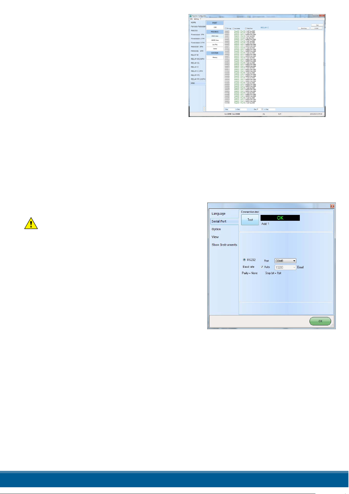
13.6.7 MSG view
Message view display the communication activity between
the computer and the power controller.
PORT
COM: use this view to see when the COM port is accessed
and its settings
MODBUS: Modbus communication protocol area
READ Area: use this view to see parameters being polled
READ Area -> En Log: enable a short read communication
log activity
READ Area -> En Detail: if En Log enabled enable a
detailed read communication log activity
READ Area -> Only Error: if En Log enabled enable a
read communication log activity only if in error
WRITE Area: use this view to see what parameters and the value are send power control
READ Area -> En Log: enable a write communication log activity
Log Msg: use this view to see the “Data Log” protocol detail when Data Log windows is active
Status: view the status and settings of the COM port
SYSTEM
Memory: view the memory usage of the Congurator program on the computer
13.6.8 Settings window
Use this window to choose user-settable options for the Congurator software.
Language:
Available Languages: choose the language used in the program
NOTE! to be active the language change, need close
and open again the conguration software
Serial Port: Set the serial port parameter
Test: click to test for communication with a power
controller via the selected port
Port: select the computer’s COM port to use to
communicate with power controllers
Baud rate: select Auto to allow the Congurator to set
the baud rate for the COM port or deselect the option to
set the baud rate yourself
Options: Set the congurator options
List Options: set whether or not parameter values are displayed in
hexadecimal in simple view recipes
Directory: set the directories in which recipes and images are saved
Disable Check Type: set to allow communication with power control-
lers that are not precise matches for
the supported types. Used only for special version. Note that set is not memorized after software shutdown
View:
Hide Tool Bar: future use
Hide Status Bar: select to hide the status bar that appears at the bottom of the program window
Show Instruments: Hide or show the available instrument in the left side of main windows
www.west-cs.co.uk 48
Page 49
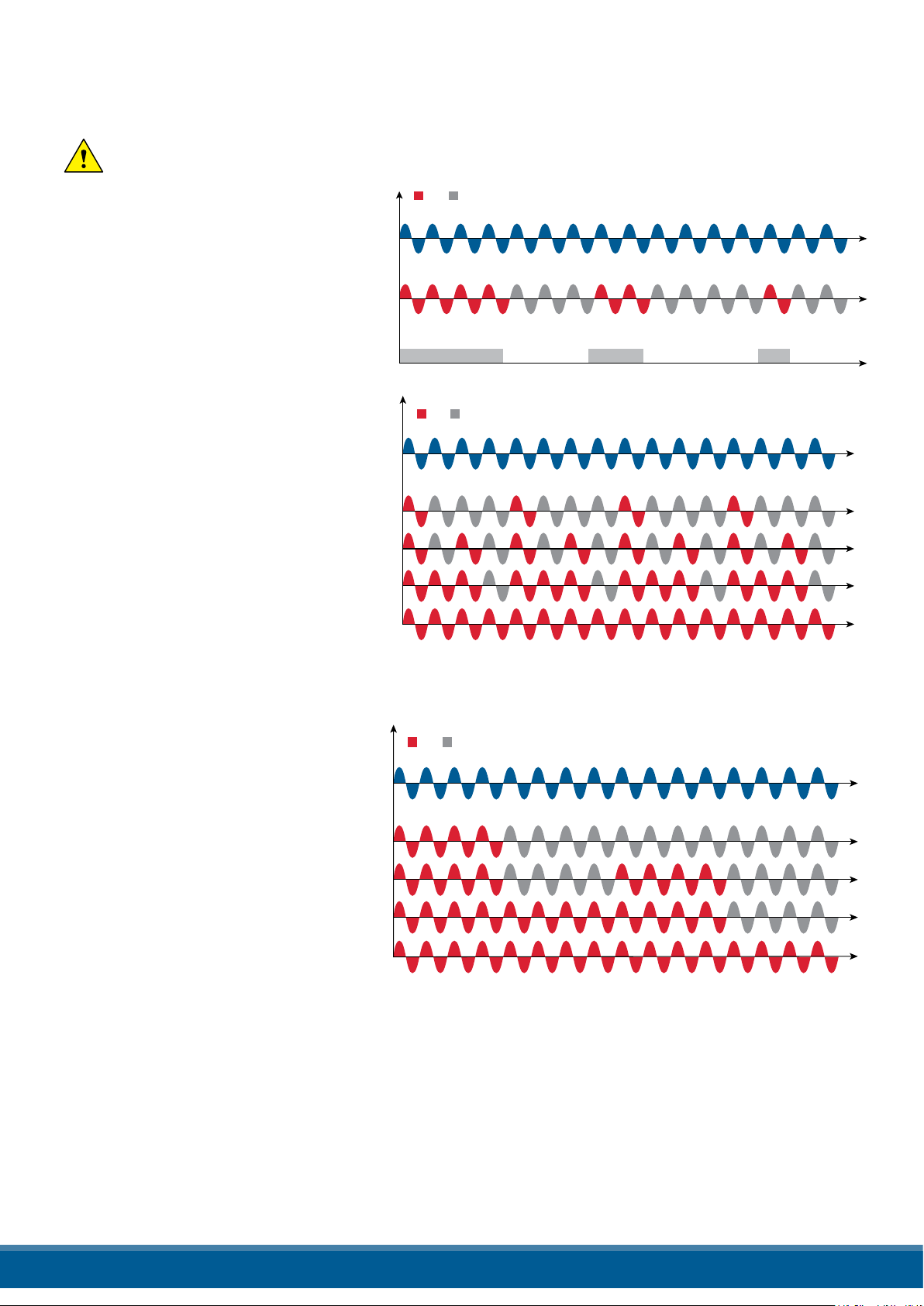
14. Firing type
Voltage Supply (V)
Load Voltage (V)
SSR from controller
ON OFF
Voltage Supply (V)
Load Voltage (V)
25%
50%
75%
100%
ON OFF
Choose a correct ring type allows to optimize the thyristor unit for the installed load.
The ring type has already congured in line with customer requirements that are dened in the Order Code.
The Order Code is written on the identication label.
However, if you wish to change the ring type you can use the software congurator or the Control Panel.
Caution: this procedure must be performed only by qualied persons.
14.1 Zero Crossing
ZC ring mode is used with Logic
Output from temperature controllers
and the Thyristor operates like a
cont actor.
The Cycle time is performed by
temperature controller. ZC minimizes
interferences because the Thyristor
unit switches ON-OFF at zero voltage.
14.2 Single Cycle
Single Cycle it’s the faster zero
crossing switching method in
relationship of the power demand
from a temperature regulator or from
an external signal.
With input signal at 25% the output is
one cycle ON and three cycles OFF
With input signal at 50% the output is
one cycle ON and one cycle OFF
With input signal at 75% the output is
three cycles ON and one cycle OFF
With input signal at 76% the output
is the same of 75% but for each ON
cycle the microprocessor divides
76/75, and when the sum of rests is
one, the unit does one more cycle ON. For this ring is necessary to have analog input.
The Single Cycle is used to control the loads with low inertia or for infrared lamps to short wave.
ON OFF
Voltage Supply (V)
Load Voltage (V)
25%
50%
75%
100%
14.3 Burst Firing
The Burst Firing is similar to the Single
Cycle, but consecutive cycles ON are
selectable between 1 and 255, with
input signal equal at 50%. When 1 is speci-
ed, the ring type is Single Cycle.
Burst Firing is a method zero crossing
that it reduces the electromagnetic
interferences because the thyristor
switches at zero voltage crossing.
The example show the Burst Firing
with Burst cycles=4.
www.west-cs.co.uk 49
Page 50
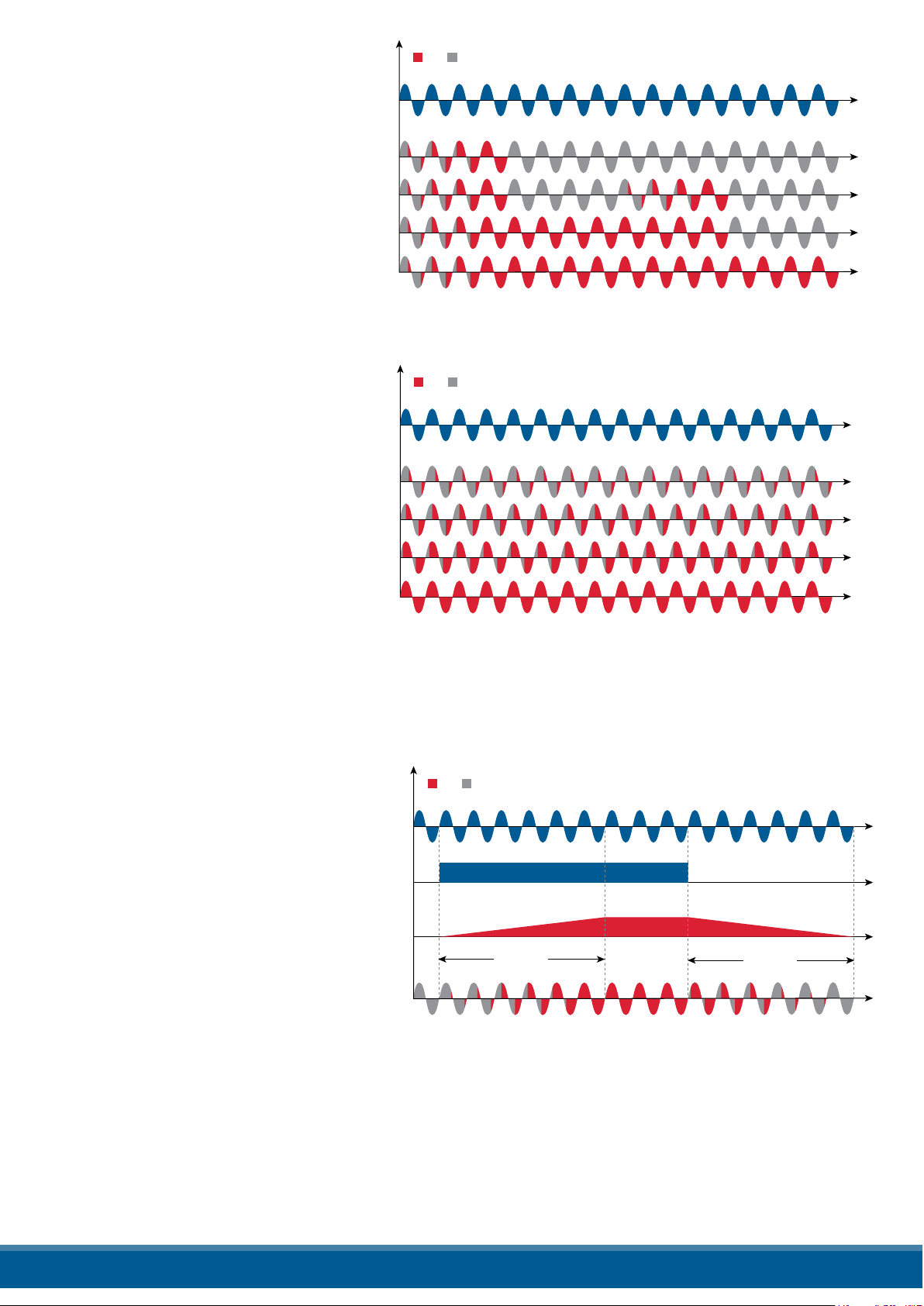
14.4 Soft Start with Burst Firing
Voltage Supply (V)
Load Voltage (V)
25%
50%
75%
100%
ON OFF
Voltage Supply (V)
Load Voltage (V)
25%
50%
75%
100%
ON OFF
Voltage Supply (V)
Output Voltage (V)
ON OFF
Setpoint Value (%)
Load Voltage RMS (V)
Ramp Up
Ramp Down
This is an additional function to the Burst
Firing. The unit start in phase angle mode
with a ramp starting from zero up to the full
tension in the cycles number set in the
parameter.
When the ramp is over, the thyristor unit will
stay in conduction at full voltage up to the end
of cycles of
burst. The S+BF ring is used to control small
inductive loads to avoid inrush surge current
and to reduce the electromagnetic interferences.
The example show the ring with Burst
cycles =4 and start ramp half cycles=3.
14.5 Phase Angle
The Phase Angle ring allow the control
of the power on the load, for this ring
the thyristor can be in conduction only
for a part of the voltage cycle.
This part of the voltage cycle is
adjustable in function of the input signal
from 0 at 100%.
The PA ring is normally used for control
the inductive loads, and is also possible
control a primary of transformer
coupled with the cold resistances like:
Superkanthal, Molybdenum, Platinum,
Tungsten or Quartz Lamp. The only
disadvantage with phase angle is the
possible generation of interferences
that however can be reduced with opportune
lters.
14.6 Soft Start with Phase Angle
This is an additional function to the
Phase Angle. The ring angle of the
thyristor increase or decrease up to the
nal setpoint value.
The Soft start ramp is an important
feature to reduce the inrush current
with transformers during the during
the cycle of magnetization or with cold
resistance that are near to the short
circuit when they are supplied.
Setpoint Ramp Up / Setpoint Ramp
Down.
www.west-cs.co.uk 50
Page 51
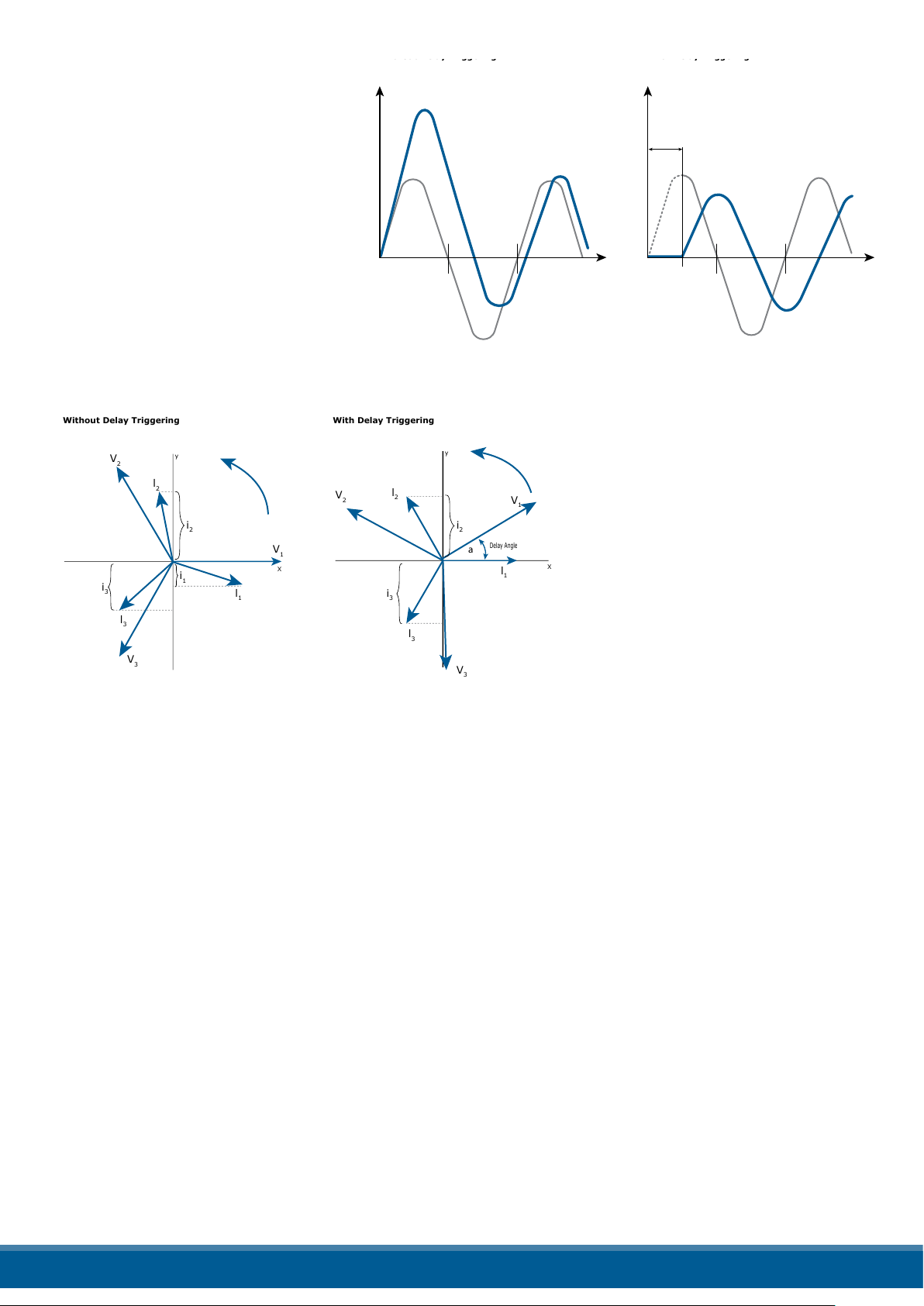
14.7 Delay Triggering with Burst Firing
Without Delay Triggering
With Delay Triggering
Without Delay Triggering With Delay Triggering
V
2
V
1
V
3
l
2
i
2
i
3
i
1
l
1
l
3
y
X
V
2
V
1
a
V
l
2
i
2
i
3
l
1
Delay Angle
l
3
y
X
The Delay Triggering ring is used
the control a primary of transformer
coupled with the normal
resistances on the secondary (N.B.
don’t connect cold resistances on
the secondary like: Superkanthal,
Molybdenum, Platinum, Tungsten,
Quartz Lamp).
For an inductive load (ex
transformer), switching the
thyristors at zero crossing can
generates transient over currents
0
that can blow the fuses, to avoid this
problem you must use the Delay
Triggering. This ring delay the rst
half cycle of Burst for an angle from
0 to 100° relative to the zero.
For understand the Delay Triggering ring, we have represented the waves generate by vectors that rotates in
counterclockwise:
over currents is reduced and the fuses don’t blow.
The angle alpha is the delay to have i1=0 and this angle depends on the power factor.
The delay angle suggest for most applications is 80°.
Transient over-current
Voltage
Zero
crossing
voltage
Current
Delay angle
(0° to 100°)
Voltage
Current
0
Zero
crossing
voltage
Without delay at zero crossing
when V1 is to zero (projected on
the X axis) the unit switch On.
In this case the instantaneous
value of the currents are i1, i2 and
i3 and this condition, for the curve
of magnetization, could generate
transient over currents that can
blow the fuses.
With Delay Triggering the ring of
the thyristor are triggered with a
delay until the instantaneous value
of the current i1=0, i2 positive and i3
negative like represented.
In this case the risk of transient
www.west-cs.co.uk 51
Page 52
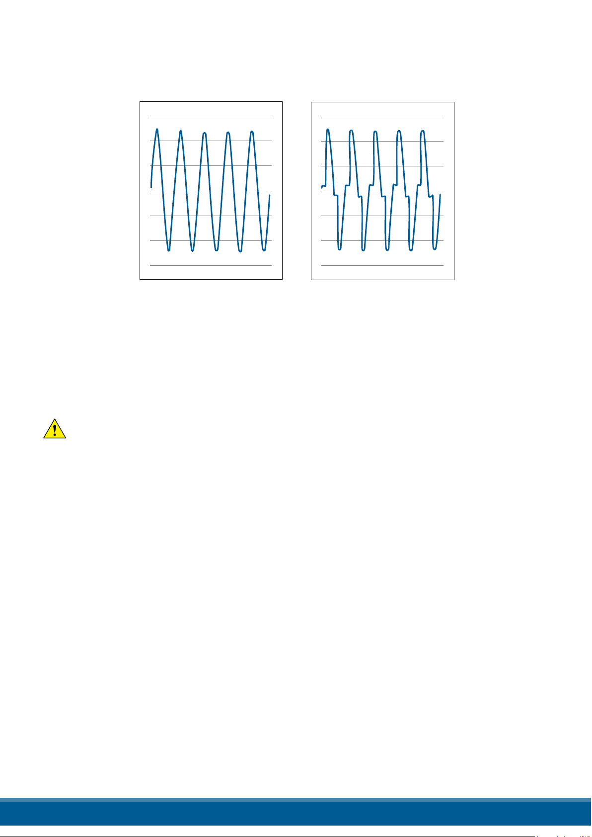
15. Current Limit
The Current Limit is available on REVO CL with Phase Angle ring mode only. It control the ring angle of the
thyristor to maintain the three RMS current under the set value. When the current exceeds this value, the voltage is
decreased up to reach the current limit set
I load ≤ I limit set I load > I limit set
15.1 Current Limit SettingThe setting of the current limit value can be done in two ways: Digital or Analogic.
• Digital: Set the parameter from the hardware menu
Set the current limit value by the parameter . from 0 to 100% of the Current. (Operator menu)
• Analogic: Set the parameter from the hardware menu
The value of the Current Limit is setted with analog input 2 Terminals 11 (-) e 4 (+).
This analog input is 0 – 10V and input impedance 10Kohm.
The settings functions by the analogic input 2 is called also External current limit prole because allows to change the
prole of the Current Limit during the process.
Caution: this procedure must be performed only by qualied persons.
15.2 Current Limit tuning procedure
• Give the power supply and set the current limit to zero:
- In analog mode, set the analog input 2 to zero
- In digital mode, set the parameter=0
• Start the thyristor unit.
• Set the primary input or the setpoint value at 100%
• Increase the current limit
- In analog mode increase the value of the analog input
- In digital mode increase the parameter until to reach the desired value of rms current.
• Stop the thyristor unit.
The Current Limit Procedure is done.
www.west-cs.co.uk 52
Page 53

16. Bakeout in function
16.1 What is heater bakeout?
If a MgO-insulated heater element shuts down for a long period of time (or sits in storage), it can absorb moisture. If
full power is applied, excessive current can damage the heater or blow fuses.
The heater bakeout feature soft starts the load to remove moisture from the heater and prevent blown heaters and
fuses.
16.2 How does heater bakeout work?
During heater bakeout, the Power Unit slowly increases voltage to the heater while monitoring the output current:
• If the heater achieves full output before the bakeout time expires, then the heater is dry and can be put into service.
• If the output current reaches a user-specied trip point during the bakeout - as it would if arcing occurred in the
heater - then the Power Unit shuts o the output and activates an alarm.
www.west-cs.co.uk 53
Page 54

17. Control Mode (feed-back)
The Control Mode (feed-back) type has already congured in line with customer requirements that are dened
in the Order Code. The Order Code is written on the identication label.
However, if you wish to change the Control Mode (feed-back) type you can use the software congurator or
the Control Panel.
Caution: this procedure must be performed only by qualied persons.
The Control Mode (feed-back) type is dened by the parameter Control Mode (feed-back) in setup menu.
If the congurable digital input has set like feed-back Selection, it’s possible to change the select feed-back
with the Voltage feed-back (V) simply activating the input.
It’s possible to have:
2
V
V2 = Square Voltage feed-back.
The input signal is proportional to the output square voltage. This means that input signal becomes a power
demand. The power remains constant if the load impedance doesn’t change.
V
V = Voltage feed-back.
The input signal is proportional to the output voltage. This means that input signal becomes a voltage demand.
This control mode compensates the voltage uctuation of the incoming line supply.
I
I = Current feed-back.
The input signal is proportional to the current output. This means that input signal becomes a current demand.
This control mode maintain the current also if the load impedance changes.
VxI
P(VxI) = Power feed-back.
The input signal is proportional to the power output. This means that input signal becomes a power demand.
The power remains constant also if voltage and load impedance change. This control mode is used with silicon
carbide elements that change its resistive value with temperature and with age. In addition it compensates the
voltage uctuation of the incoming line supply.
2
I
I2 = Square Current feed-back.
The input signal is proportional to the output square curren. This means that input signal becomes a power
demand. The power remains constant if the load impedance doesn’t change.
None = No feed-back Open Loop. The input is proportional to the ring angle (α).
EXT
External = External feed-back (0÷10V, 4÷20mA, 0÷20mA).
The input signal is proportional to an external signal. This means that input signal becomes a demand to
maintain this signal always constant. This control mode is used for example with galvanic systems, where it’s
necessary to control the current value through the electrodes.
www.west-cs.co.uk 54
Page 55
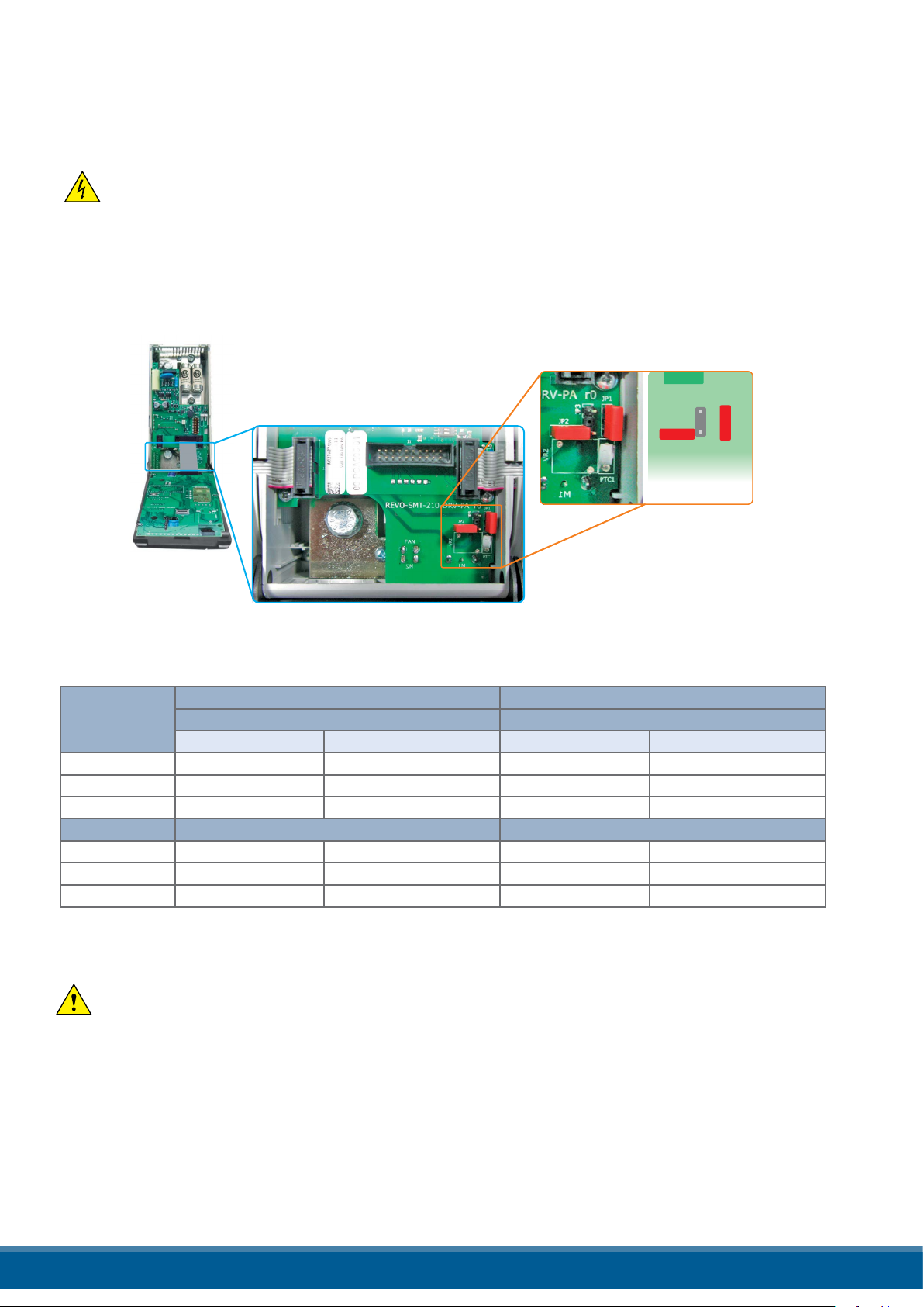
18. Supply the Electronic Board
JP2
JP3
JP1
The Relay C thyristor unit, to work, requires a voltage supply for the electronic boards. The Max consumption
is 10VA.
The voltage supply for the electronic boards is congured in line with customer requirements that are dened
in the Order Code. The Order Code is written on the identication label.
Warning: Before connecting or disconnecting the unit check that power and control cables
are isolated from voltage sources.
To change auxiliary supply voltage sold the correct link-jumper on Relay C board
The type of mounted transformer depends of the chosen Voltage in the order code.
As ordered Change to
Order Code
Transformer range Line voltage Transformer range Line voltage
RC3_ _ _-_1 90:135V 100/120V 180:265V 200/208/220/230/240V
RC3_ _ _-_2 180:265V 200/208/220/230/240V 342:528V 380/400/415/440/480V
RC3_ _ _-_3 238:330V 277V 540:759V 600/690V
RC3_ _ _-_5 342:528V 380/400/415/440/480V 180:265V 200/208/220/230/240V
RC3_ _ _-_6 540:759V 600V 238:330V 277V
RC3_ _ _-_7 540:759V 690V 238:330V 277V
Jumper JP1 + JP2 are linked Link only Jumper JP3
Only Jumper 3 is linked Link Jumper JP1 + JP2
Attention! never link all the jumpers JP1+JP2+JP3 at the same time or JP3 + any other jumper,
JP3 must be always alone, follow only the conguration shown.
www.west-cs.co.uk 55
Page 56

19. RS485 Serial port
M1 Terminal Description
11 RS485 A+
12 RS485 B-
The serial communication port RS485 is available on the Command.
On this port may be done a network up to 127 Relay C.
20. Fieldbus communication option
Other serial communication port are available as option, see Communication Manual for details.
Ethernet Conguration Probus Conguration
Second Serial 485 Conguration Connectors M4
5 4 3 2 1
M4 Terminal Description
1 +24V
2 GND
3 Not connected
4 RS485 A+
5 RS485 B-
www.west-cs.co.uk 56
Page 57
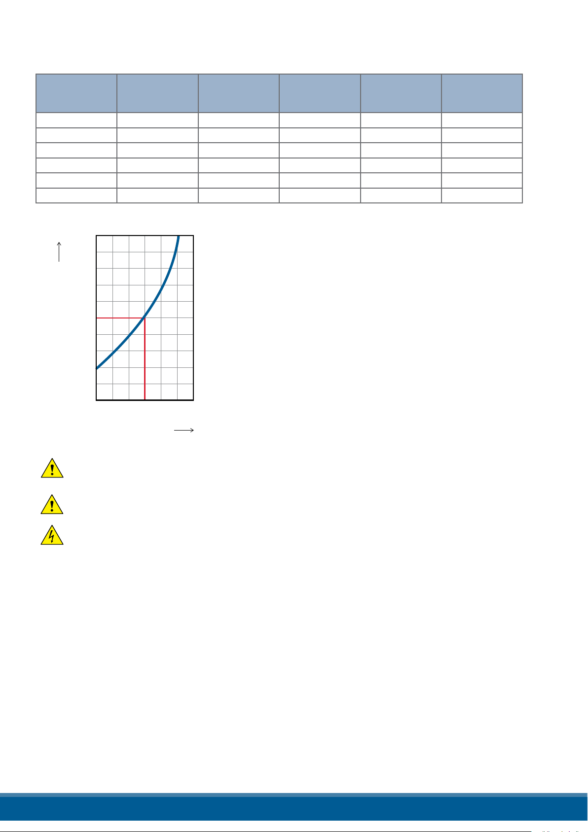
21. Internal Fuse
The thyristor unit have internal fuse extrarapid at low I²t for the thyristor protection of against the short-circuits.
The Fuses must have I²t 20% less than thyristor’s I²t. The warranty of thyristor is null if no proper fuses are used.
Type Fuse Code Spa-
re Part
060 20 559 20.160 160 660 10780 15400
090 20 559 20.160 160 660 10780 15400
120 20 559 20.180 180 660 14280 20400
150 20 559 20.200 200 660 17500 25000
180 20 559 20.250 250 660 30800 44000
210 20 559 20.315 315 660 53900 77000
1.2
1.0
Current (ARMS) Vac FUSE I2T value
Suggested A2s
(at500V)*
*I2T are multiplied for K value in function of Vac at 500V K is
equal to 0,7 (ex:15400 X 0,7 = 10780).
At 660Vsc K is equal to 1.
FUSE I2T value
Suggested A2s
K
0.8
0.7
0.6
0.4
(at660V)
0.2
200 400 600 800
500
Vca
(Line Voltage)
Caution: High speed fuses are used only for the thyristor protection and can not be used to
protect the installation.
Caution: The warranty of thyristor is null if no proper fuses are used. See tab.
Warning: When it is supply, the Thyristor unit is subject to dangerous voltage, don’t open the
Fuse-holder module and don’t touch the electric equipments.
www.west-cs.co.uk 57
Page 58
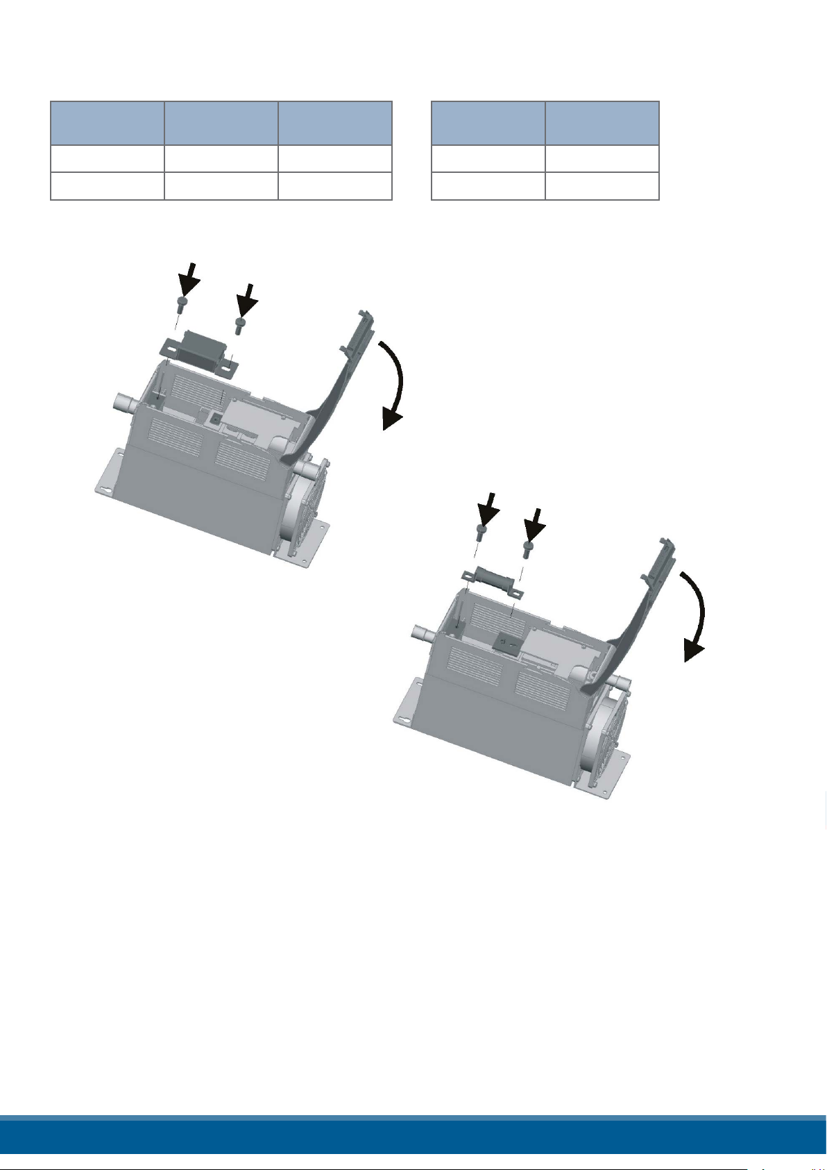
21.1 Fuses Replacement
Open the cover and remove the screws, then replace it with the correct fuse, use the screws with a proper
suggested torque indicated below:
Type Screw
60-120A M6 44.2 (5.0)
150-210A M6 44.2 (5.0)
Torque
Lb-in (N-m)
+
Screw
M5 31 (3.5)
Torque
Lb-in (N-m)
www.west-cs.co.uk 58
Page 59

Contact
UK
Email: enquiries@west-cs.com
Website: www.west-cs.co.uk
Telephone: +44 (0)1273 606271
Address: The Hyde Business Park
Brighton, East Sussex
BN2 4JU
United Kingdom
West Control Solutions is part of the Fortive Corporation.
Specications are subject to change without notice, as a result
of our continual development and improvement, E&OE.
www.west-cs.co.uk
Brazil
Email: atendimento@ftvindtech.com
Website: www.west-cs.com.br
Telephone: 55 11 3616-0195 / 55 11 3616-0159
China
Email: china@west-cs.cn
Website: www.west-cs.cn
Telephone: +86 400 666 1802
France
Email: fr@west-cs.com
Website: www.west-cs.fr
Telephone: +33 171 84 1732
Germany
Email: de@west-cs.com
Website: www.west-cs.de
Telephone: +49 561 505 1307
USA
Email: inquiries@west-cs.com
Website: www.west-cs.com
Telephone: +1 800 866 6659
UM-RC362-1-UK-1902
 Loading...