

Page 1

Page 2
Pro-EC44
2-Loop Graphical Profile
Controller & Recorder
Pro-EC44 User Guide 59540-1
Page 3

Page 4
Pro-EC44 2-Loop Graphical Profile Controller & Recorder
WARNING: THE INTERNATIONAL HAZARD SYMBOL IS INSCRIBED
ADJACENT TO THE REAR CONNECTION TERMINALS. IT IS IMPORTANT
TO READ THIS MANUAL BEFORE INSTALLING OR COMMISSIONING THE
UNIT.
WARNING: THIS SYMBOL MEANS THE EQUIPMENT IS PROTECTED
THROUGHOUT BY DOUBLE INSULATION.
WARNING: PRODUCTS COVERED BY THIS MANUAL ARE SUITABLE FOR
INDOOR USE, INSTALLATION CATEGORY II, POLLUTION CATEGORY 2
ENVIRONMENTS.
Note: It is strongly recommended that applications incorporate a high or low limit
protective device, which will shut down the equipment at a pre-set process
condition in order to prevent possible damage to property or products.
This manual supplements the Concise Product manual supplied with each instrument at the
time of shipment. Information in this installation, wiring and operation manual is subject to
change without notice.
Copyright © October 2013, Danaher Corporation, all rights reserved. No part of this
publication may be reproduced, transmitted, transcribed or stored in a retrieval system, or
translated into any language in any form by any means without the written permission of
Danaher/West Control Solutions.
Copies of this manual are available in electronic format on the West Control Solutions web
site (www.west-cs.com) Printed versions may be purchased from West Control Solutions or
its representatives.
This user guide covers all versions of the West Pro-EC44 controller.
©WCS – Product & specifications may be subject to change without notice - E&OE
Pro-EC44 Product Manual - 59540-1 October 2013 Page i
Page 5

Pro-EC44 2-Loop Graphical Profile Controller & Recorder
Warranty and Returns Statement
These products are sold by West Control Solutions under the warranties set forth in the
following paragraphs. Such warranties are extended only with respect to a purchase of these
products, as new merchandise, directly from West Control Solutions or from a West Control
Solutions distributor, representative or reseller and are extended only to the first buyer
thereof who purchases them other than for the purpose of resale.
Warranty
These products are warranted to be free from functional defects in material and workmanship
for three years from the time the products leave West Control Solutions factory and to
conform at that time to the specifications set forth in the relevant West instruction manuals
sheet or sheets.
THERE ARE NO EXPRESSED OR IMPLIED WARRANTIES, WHICH EXTEND BEYOND THE
WARRANTIES HEREIN AND ABOVE SET FORTH. NO WARRANTY IS MADE OF
MERCHANTABILITY OR FITNESS FOR A PARTICULAR PURPOSE WITH RESPECT TO THE
PRODUCTS.
Limitations
West Control Solutions shall not be liable for any incidental damages, consequential
damages, special damages, or any other damages, costs or expenses excepting only the
cost or expense of repair or replacement as described above. Products must be installed and
maintained in accordance with West Control Solutions instructions. There is no warranty
against damage to the product resulting from corrosion. Users are responsible for the
suitability of the products to their application.
For a valid warranty claim, the product must be returned carriage paid to the supplier within
the warranty period. The product must be properly packaged to avoid damage from
electrostatic discharge or other forms of harm during transit.
Page ii Pro-EC44 Product Manual - 59540-1 October 2013
Page 6

Pro-EC44 2-Loop Graphical Profile Controller & Recorder
How to use this manual
This manual is structured to give easy access to the information required for all aspects of
the installation and use and of the controller. The main sections are shown here, with a full
table of contents at the end.
Warranty and Returns Statement ..................................................................................................... ii
1 Introduction............................................................................................................................. 1
2 Installation .............................................................................................................................. 2
3 Field Upgrade Options ........................................................................................................... 4
4 Electrical Installation .............................................................................................................. 9
5 Powering Up .......................................................................................................................... 29
6 Messages & Error Indications.............................................................................................. 31
7 Application Setup ................................................................................................................. 33
8 Operation and Configuration Menus ................................................................................... 36
9 Input Calibration & Multi-point Scaling ............................................................................... 70
10 Digital Inputs ......................................................................................................................... 75
11 Cascade Control ................................................................................................................... 78
12 Ratio Control ......................................................................................................................... 81
13 Redundant Input ................................................................................................................... 83
14 Valve Motor Drive / 3-Point Stepping Control ..................................................................... 84
15 Setpoint Sources .................................................................................................................. 86
16 Profiler ................................................................................................................................... 87
17 USB Interface ........................................................................................................................ 96
18 Data Recorder ................................................................ ....................................................... 97
19 Controller Tuning.................................................................................................................. 99
20 Serial Communications ...................................................................................................... 109
21 Glossary .............................................................................................................................. 204
22 PC Software ........................................................................................................................ 235
23 Specifications ..................................................................................................................... 245
24 Pro-EC44 Product Coding .................................................................................................. 255
25 Table of Contents ................................................................ ............................................... 257
Pro-EC44 Product Manual - 59540-1 October 2013 Page iii
Page 7

Page 8

Pro-EC44 2-Loop Graphical Profile Controller & Recorder
1 Introduction
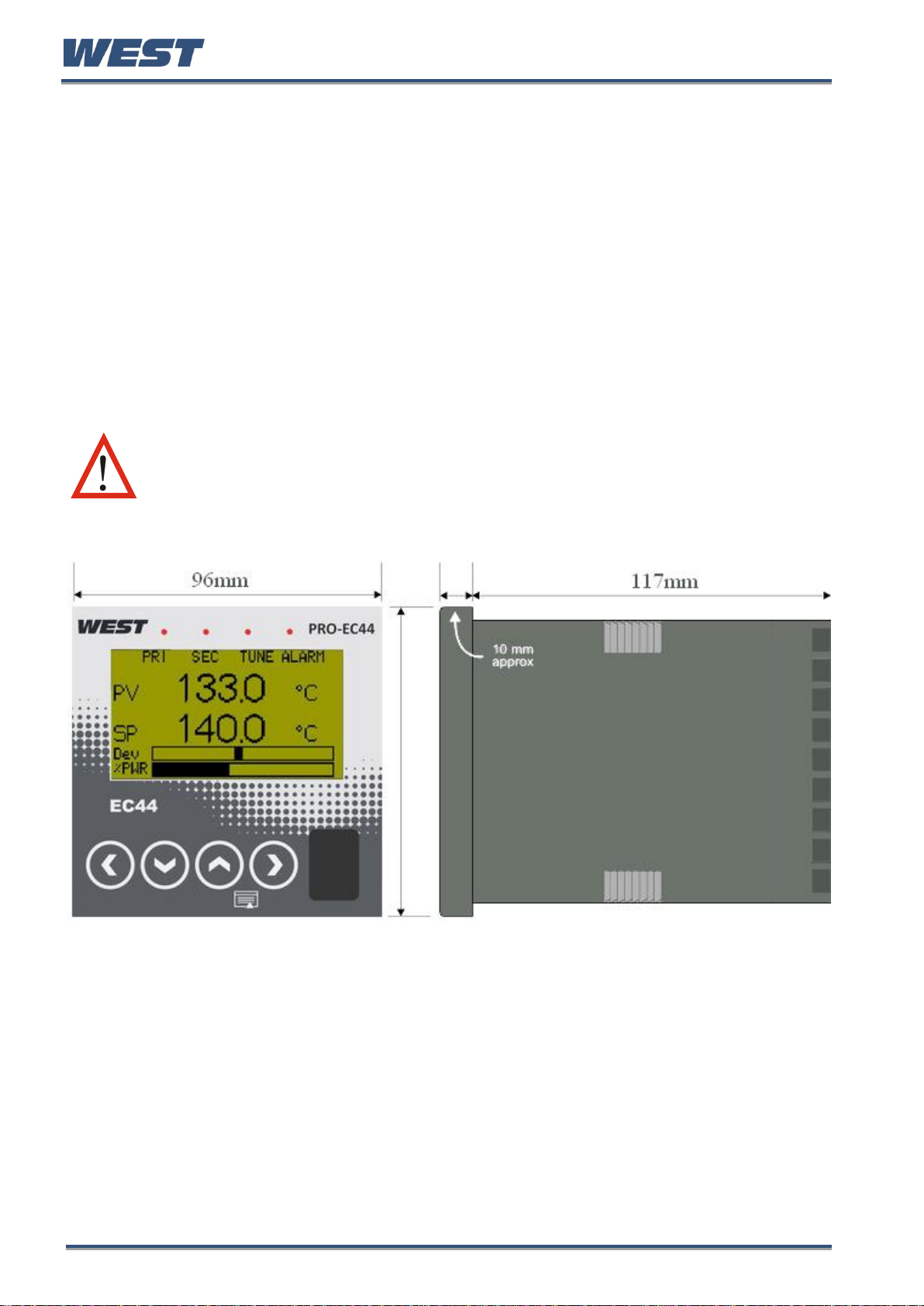
This product is a 1/4 DIN size (96 x 96mm front) microprocessor based graphical process
controller, featuring a 160 x 80 pixel, monochrome LCD with dual colour (red/green)
backlight. It operates from 100-240V at 50/60 Hz or 24V-48V AC/DC, depending on the
model purchased. It can measure and control up to two process variables from a variety of
sources such as temperature, pressure, flow and level. Primary and secondary control
outputs are possible for each loop.
Optional features include a second process input, USB interface, remote setpoint inputs
RS485 or Ethernet communications, profile control and data recording. Control options
include cascade, ratio and 3-point stepping valve control. Automatic tuning or 5 stage gainscheduling are also available.
The USB Interface option allows uploading or downloading instrument configuration settings
to/from a USB memory stick, for easy configuration of multiple instruments or transfer to/from
the PC configuration software. If the data recorder or profiler options are fitted, recordings
and profile information can be transferred via the memory stick.
The data recorder option allows the user to make recordings of the processes over time.
Recordings can be transferred to a memory stick using the USB interface or downloaded via
one of the communications options.
The Profiler option allows the user to predefine up 255 segments, shared amongst up to 64
Setpoint Profiles. These control the setpoint levels for the control loop(s) over time,
increasing, decreasing or holding their values as required. When combined with the real-time
clock (part of the Data Recorder option) the profiling capabilities are expanded to allow
automatic program start at a defined time and day.
Inputs are user configurable for thermocouple and RTD probes, as well as linear process
signal types such as mVDC, VDC or mADC. Two-point calibration or multipoint scaling can
compensate for errors or non-linear signals. Output options include single or dual relays,
single or dual SSR drivers, triacs or linear mA/V DC. These can be used for process control,
alarms/events or retransmission of the process variable or setpoint to external devices.
Transmitter power supply options can provide an unregulated 24V DC (22mA) auxiliary
output voltage, or a 0 to 10VDC stabilised excitation for external signal transmitters.
Up to 7 alarms can be defined as process high or low, deviation (active above or below
controller setpoint), band (active both above and below setpoint), rate of input change,
control loop, PID power or signal break types. Alarm status can be indicated by lighting an
LED, changing the display backlight colour or viewing the active alarm status screen. These
alarms can be linked to any suitable output.
Configuration for basic applications is possible using the easy Setup Wizard run
automatically at first power-up or manually later. Access to the full range of parameters is via
a simple menu driven front panel interface, or the PC based configuration software.
Pro-EC44 Product Manual - 59540-1 October 2013 Page 1
Page 9
Pro-EC44 2-Loop Graphical Profile Controller & Recorder
CAUTION: Installation should be only performed by technically competent
personnel. It is the responsibility of the installing engineer to ensure that
the configuration is safe. Local Regulations regarding electrical installation
& safety must be observed (e.g. US National Electrical Code (NEC) or
Canadian Electrical Code).
2 Installation
Unpacking
1. Remove the product from its packing. Retain the packing for future use, in case it is
necessary to transport the instrument to a different site or to return it to the supplier for
servicing.
2. The instrument is supplied with a panel gasket and push-fit mounting clamp. A multi-page
concise manual is supplied with the instrument, in one or more languages. Examine the
delivered items for damage or defects. If any are found, contact your supplier
immediately.
Installation
Figure 1. Main dimensions
Panel-Mounting
The controller should be mounted in a properly earthed metal cabinet. The mounting panel
must be rigid and may be up to 6.0mm (0.25 inches) thick. The cut-out size is:
92mm x 92mm (+0.5mm / -0.0mm).
Pro-EC44 Product Manual - 59540-1 October 2013 Page 2
Page 10
Pro-EC44 2-Loop Graphical Profile Controller & Recorder
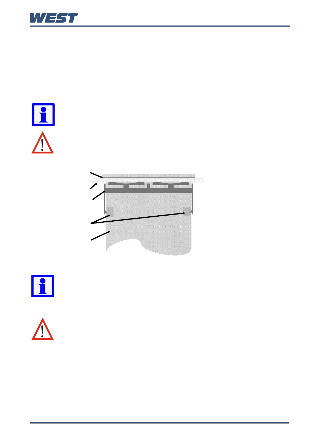
Note: The mounting clamp tongues may engage the ratchets either on the sides
or the top/bottom faces of the Instrument housing. When installing several
Instruments side-by-side in one cut-out, use the ratchets on the top/bottom faces.
CAUTION: Ensure the inside of the panel remains within the instrument
operating temperature and that there is adequate airflow to prevent
overheating.
Gasket
Mounting Panel
Clamp
Ratchets
Instrument
Housing
1. Insert instrument into the
panel cut-out.
2. Hold front bezel firmly
(without pressing on the
display area), and re-fit
mounting clamp. Push the
clamp forward, using a tool if
necessary, until gasket
compresses and instrument
is held firmly in position.
CAUTION: Do not remove the panel gasket, as this may result in inadequate
clamping and sealing of the instrument to the panel.
Note: For an effective IP66 seal against dust and moisture, ensure gasket is well
compressed against the panel, with the 4 tongues located in the same ratchet
slot.
Instruments may be mounted side-by-side in a multiple installation, but instrument to panel
moisture and dust sealing will be compromised. Allow a 20mm gap above, below and behind
the instrument for ventilation. The cut-out width (for n instruments) is:
(96n - 4) mm or (3.78n - 0.16) inches
If panel sealing must be maintained, mount each instrument into an individual cut-out with
10mm or more clearance between the edges of the holes.
Figure 2. Panel-Mounting the instrument
Once the instrument is installed in its mounting panel, it may be subsequently removed from
its housing if necessary, as described in the Fitting and Removing Plug-in Modules section.
Cleaning
Clean the front panel by washing with warm soapy water and dry immediately. If the USB
option is fitted, close the USB port cover before cleaning.
Pro-EC44 Product Manual - 59540-1 October 2013 Page 3
Page 11
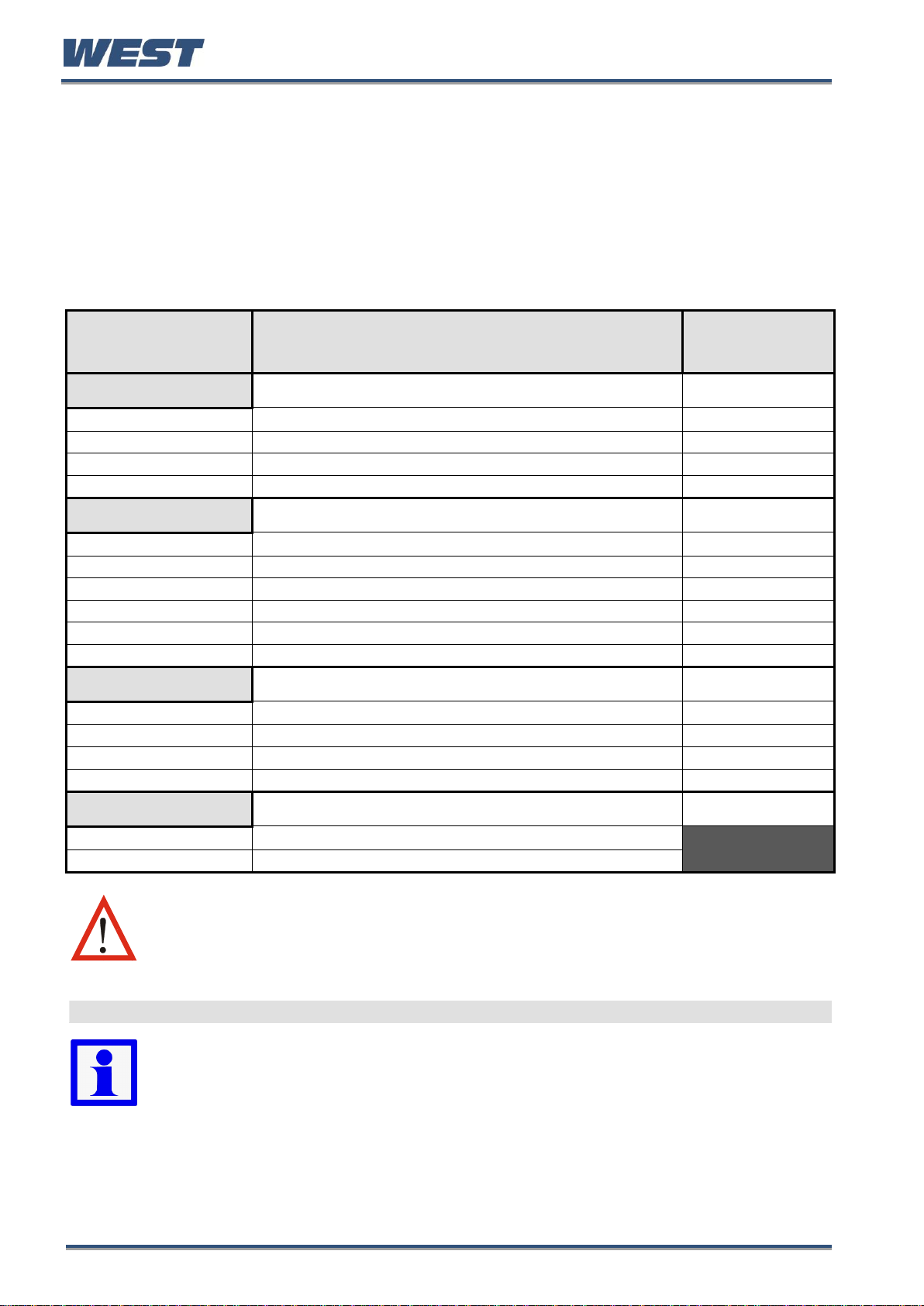
Pro-EC44 2-Loop Graphical Profile Controller & Recorder
PART
NUMBER
AVAILABLE OPTIONS & ACCESSORIES
BOARD
IDENTIFICATION
NUMBER
MODULE SLOT 1
PO1-R10
Single Relay Output for plug-in module slot 1
716/01
PO1-S20
Single SSR Driver Output for plug-in module slot 1
716/02
PO1-T80
Triac Output for plug-in module slot 1
716/03
PO1-C21
Linear mA / Voltage Output for plug-in module slot 1
639/01
MODULE SLOT 2 or 3
PO2-R10
Single Relay Output for plug-in module slot 2 or 3
717/01
PO2-W09
Dual Relay Output for plug-in module slot 2 or 3
644/01
PO2-S20
Single SSR Driver Output for plug-in module slot 2 or 3
717/02
PO2-S22
Dual SSR Driver Output for plug-in module slot 2 or 3
644/02
PO2-T80
Triac module Output for plug-in module slot 2 or 3
647/01
PO2-W08
24VDC Transmitter Power Supply for module slot 2 or 3
642/01
MODULE SLOT A
PA1-W03
Digital Input for plug-in module slot A
641/02
PA1-W04
Basic Auxiliary Input for plug-in module slot A
653/01
PA1-W06
RS485 Serial Communications for plug-in module slot A
680/01
PA1-ETH
Ethernet Communications for plug-in module slot A
707/01
ACCESSORIES
PS1-PRF
Profiler Enable Key-code
PS1-PRW
Blue Control PC Configuration Software & Lead
CAUTION: Plastic pegs prevent fitting of older non-reinforced single relay
modules (board identification numbers 637/01 and 638/01). Fitting the older
relay modules reduces the isolation rating to Basic 240V isolation and is
therefore not recommended.
Remove this peg when fitting Dual Relay Modules.
Board Positions
Note: All dual relay modules have reinforced isolation.
3 Field Upgrade Options
Plug-Modules and Upgradeable Functions
Plug-Modules can be either pre-installed at the time of manufacture, or retrofitted in the field
to expand the capabilities of the controller. Contact your supplier to purchase these items.
Part numbers and circuit board identification numbers for the plug-in modules and
accessories are shown in below:
Pro-EC44 Product Manual - 59540-1 October 2013 Page 4
Page 12
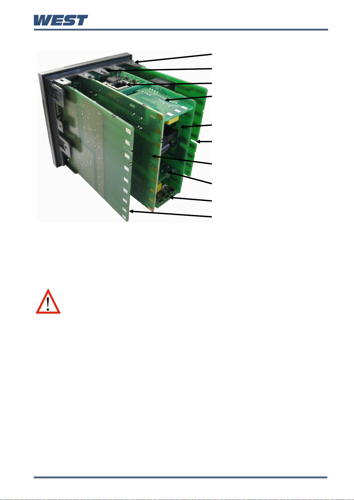
Pro-EC44 2-Loop Graphical Profile Controller & Recorder
Board Mounting Struts (x4)
Front Panel Removal Latch (x1)
Plug-in Module A
Plug-in Module 3
Power Supply Board
2nd Universal Input & Base
Option 2 Board
1st Universal Input & Base
Option 1 Board
Plug-in Module 1
Plug-in Module 2
USB/Digital Input C Option
Board
CAUTION: Before removing the instrument from its housing, ensure that all
power has been removed from the rear terminals. Modules / boards should
be replaced by a technically competent technician.
Figure 3. Rear view (uncased) & board positions
Preparing to Install or Remove Plug-in Modules
1. Grip the edges of the front panel (there is a finger grip on each edge) and pull it forwards
approximately 10mm, until the Front Panel Removal Latch prevents further movement.
The purpose of the latch is to prevent removal of the instrument without the use of a tool.
2. The Front Panel Removal Latch must be pushed down to allow removal of the instrument.
Using a tool (e.g. screwdriver or pen tip), press down it down through the front central
ventilation hole. This will release the instrument from the case.
3. The internal boards can now be accessed. Take note of the orientation of the instrument
and boards for subsequent replacement into the housing. The positions of the boards,
their mountings and the Front Panel Removal Latch are shown above.
Pro-EC44 Product Manual - 59540-1 October 2013 Page 5
Page 13
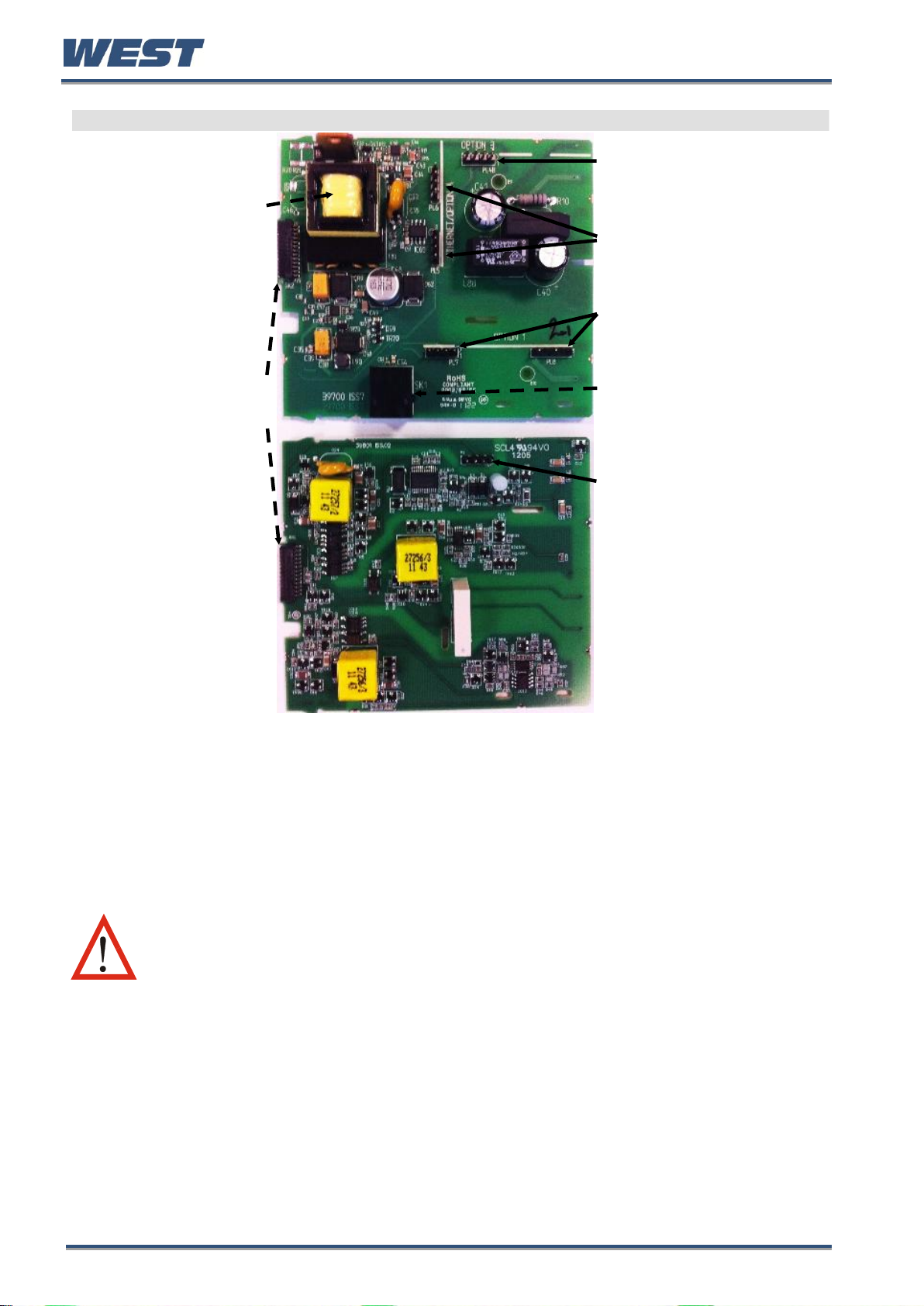
Pro-EC44 2-Loop Graphical Profile Controller & Recorder
Main Board Connectors
POWER SUPPLY
BOARD
Transformer Colour
Code
100-240V (Yellow)
24-48V(Blue)
Display Board
Connections
1st UNIVERSAL
INPUT / BASE
OPTION 1 BOARD
Module Slot 3
Connector PL4B
Module Slot A
Connectors PL5, & PL6
Module Slot 1
Connectors PL7 & PL8
PC Configurator
Socket SK1
Module Slot 2
Connector PL4A
CAUTION: Replacement of boards must be carried out by a technically
competent technician. If the Power Supply board does not match the
labelling, users may apply incorrect voltage resulting in irreparable
damage.
This product is designed to allow the user to reconfigure some hardware options in the field
by changing the plug-in modules in slots 1, 2, 3, & A located on the power supply and 1st
universal input boards. The main boards (display/CPU, power supply, inputs 1 & 2 and digital
input/USB) are factory fitted, but may be removed while reconfiguring the plug-in modules.
Take care when re-fitting these boards. Observe the power supply board transformer colour,
and case labelling to check the supply voltage, otherwise irreparable damage may occur.
Figure 4. Main board connectors
Pro-EC44 Product Manual - 59540-1 October 2013 Page 6
Page 14

Pro-EC44 2-Loop Graphical Profile Controller & Recorder
CAUTION: Check for correct orientation of the modules and that all pins
are located correctly.
CAUTION: Before replacing the instrument in its housing, ensure that all
power has been removed from the rear terminals.
CAUTION: Ensure that the instrument is correctly orientated. A mechanical
stop will operate if an attempt is made to insert the instrument in the wrong
orientation, this stop MUST NOT be over-ridden.
Removing/Replacing Option Modules
1. To remove or replace Plug-in Modules 1, 2, 3 or A it is necessary to detach the power
supply and input boards from the front panel by lifting first the upper and then lower
mounting struts.
2. Remove or fit the modules to the connectors on the power supply and input boards. The
location of the connectors is shown below. Plastic pegs prevent fitting of older nonreinforced single relay modules – Remove the peg to fit dual relay modules
3. Assemble the Power Supply and Input boards together. Tongues on each option module
locate into slots cut into the main boards, opposite each of the connectors. Hold the Power
and Input boards together and relocate them back on their mounting struts.
4. Push the boards forward to ensure correct connection to the front Display/CPU board and
re-check the installation of the Option C and/or 2nd Input / Base Option 2 boards if present.
Replacing the Instrument in its Housing
With the required option modules correctly located into their respective positions the
instrument can be replaced into its housing as follows:
1. Hold the Power Supply and Input boards together.
2. Align the boards with the guides in the housing.
3. Slowly and firmly, push the instrument into position in its case.
Auto Detection of Plug-in Modules
The instrument automatically detects which plug-in modules have been fitted into each slot.
The menus and screens change to reflect the options compatible with the hardware. The
modules fitted can be viewed in the product information menu, as detailed in the Product &
Service Information Mode section of this manual.
Pro-EC44 Product Manual - 59540-1 October 2013 Page 7
Page 15

Pro-EC44 2-Loop Graphical Profile Controller & Recorder
CAUTION: Servicing of the Data Recorder/RTC circuit and replacement of
the lithium battery should only be carried out by a technically competent
technician.
Data Recorder Board
If installed, the Data Recorder memory and Real Time Clock (RTC) components are located
on a plug-in daughter board attached to the front Display/CPU board.
Profiler Enabling
If you purchased a controller with the Profiler option installed, these features will be enabled
during manufacture.
Controllers supplied without the Profiler option installed can be upgraded in the field by
purchasing a licence code number from your supplier. A unique code must be purchased to
enable profiling on each controller that requires it.
Entering the Profiler Enable Code
Hold down the L and D keys during the power-up “splash screen”.
Using the D or U keys, enter the 16-character licence code in the displayed screen.
Press R to move on to the next character. Press L to move back to the previous
character.
Press R after entering the final character.
To confirm if profiling is installed in your instrument, check the Controller Feature Information
in Product & Service Information Mode.
Pro-EC44 Product Manual - 59540-1 October 2013 Page 8
Page 16

Pro-EC44 2-Loop Graphical Profile Controller & Recorder
CAUTION: Installation should be only performed by technically competent
personnel. It is the responsibility of the installing engineer to ensure that
the configuration is safe. Local Regulations regarding electrical installation
& safety must be observed (e.g. US National Electrical Code (NEC) or
Canadian Electrical Code).
CAUTION: The only wires that should run together are those of the same
category.
4 Electrical Installation
Avoiding EMC Problems
This controller has passed EMC compliance tests to EN61326. There should be no difficulty
achieving this level of compliance in use, but it should be borne in mind that the wiring of the
installation can significantly reduce the efficiency of instrumentation immunity due to the ease
with which high frequency RF can enter via unprotected cables.
The following general recommendations can reduce the possibility of EMC problems.
1. If the instrument is being installed in existing equipment, wiring in the area should be
checked to ensure that good wiring practices have been followed.
2. The controller should be mounted in a properly earthed metal cabinet. All round metal
shielding is important, so the cabinet door may require a conductive sealing strip.
3. It is good practice to ensure that the AC neutral is at or near ground (earth) potential.
A proper neutral will help ensure maximum performance from the instrument.
4. Consider using a separate isolation transformer to feed only the instrumentation. A
transformer can protect instruments from noise found on the AC power supply.
Cable Isolation & Protection
Four voltage levels of input and output wiring may be used with the unit:
1. Analogue inputs or outputs (for example thermocouple, RTD, VDC, mVDC or mADC)
2. Relays & Triac outputs
3. Digital Inputs & SSR Driver outputs
4. AC power
If any wires need to run parallel with any from another category, maintain a minimum space
of 150mm between them. If wires MUST cross each other, ensure they do so at 90 degrees
to minimise interference.
Keep signal cables as short as possible. If an earthed thermocouple is used or if the sensor
has a screened cable, it should be earthed at one point only, preferably at the sensor
location or cabinet entry point, by means of a metal gland. Ideally all analogue and digital
signals should be shielded like this, but for unscreened cables, large diameter ferrite sleeves
at the cabinet entry point are an effective method of reducing RF interference. Looping
cables through the ferrite sleeves a number of times improves the efficiency of the filtering.
For mains input cables the fitting a suitable mains filter can provide good results.
Pro-EC44 Product Manual - 59540-1 October 2013 Page 9
Page 17
Pro-EC44 2-Loop Graphical Profile Controller & Recorder
Noise Suppression at Source
If possible, eliminate mechanical contact relays and replace with solid-state relays.
Noise-generating devices such as Ignition transformers, arc welders, motor drives, relays
and solenoids should be mounted in a separate enclosure. If this is not possible, separate
them from the instrumentation, by the largest distance possible.
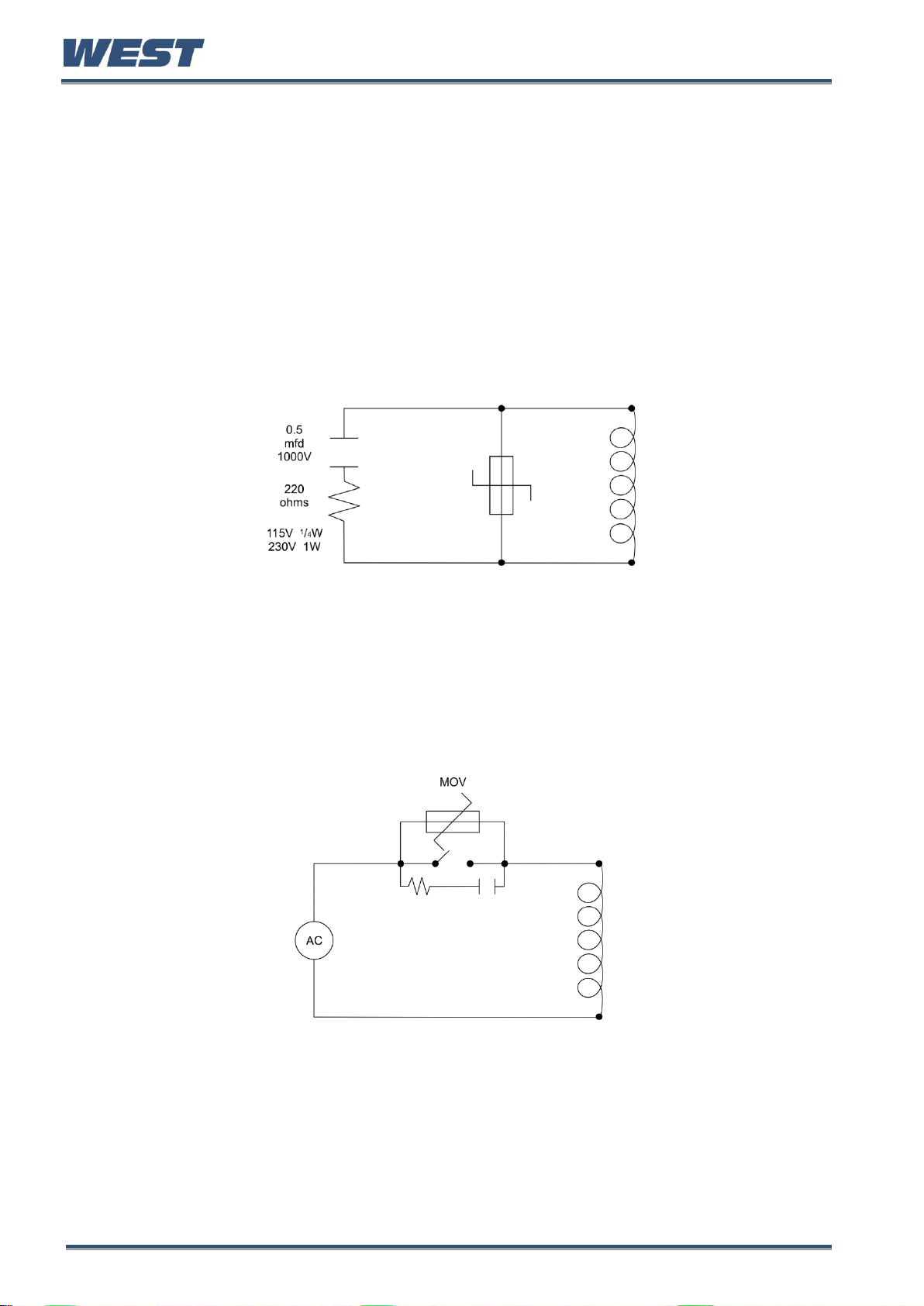
Many manufacturers of relays, contactors etc supply 'surge suppressors' to reduce noise at
its source. For those devices that do not have surge suppressors supplied, ResistanceCapacitance (RC) networks and/or Metal Oxide Varistors (MOV) may be added.
Inductive coils:- MOVs are recommended for transient suppression in inductive coils.
Connect as close as possible, in parallel to the coil. Additional protection may be provided by
adding an RC network across the MOV.
Figure 5. Transient suppression with inductive coils
Contacts:- Arcing may occur across contacts when they open and close. This results in
electrical noise as well as damage to the contacts. Connecting a properly sized RC network
can eliminate this arc.
For circuits up to 3 amps, a combination of a 47 ohm resistor and 0.1 microfarad capacitor
(1000 volts) is recommended. For circuits from 3 to 5 amps, connect two of these in parallel.
Figure 6. Contact noise suppression
Pro-EC44 Product Manual - 59540-1 October 2013 Page 10
Page 18
Pro-EC44 2-Loop Graphical Profile Controller & Recorder
CAUTION: The placement of probes into pipe work some distance from the
heating vessel leads to transport delay, which results in poor control.
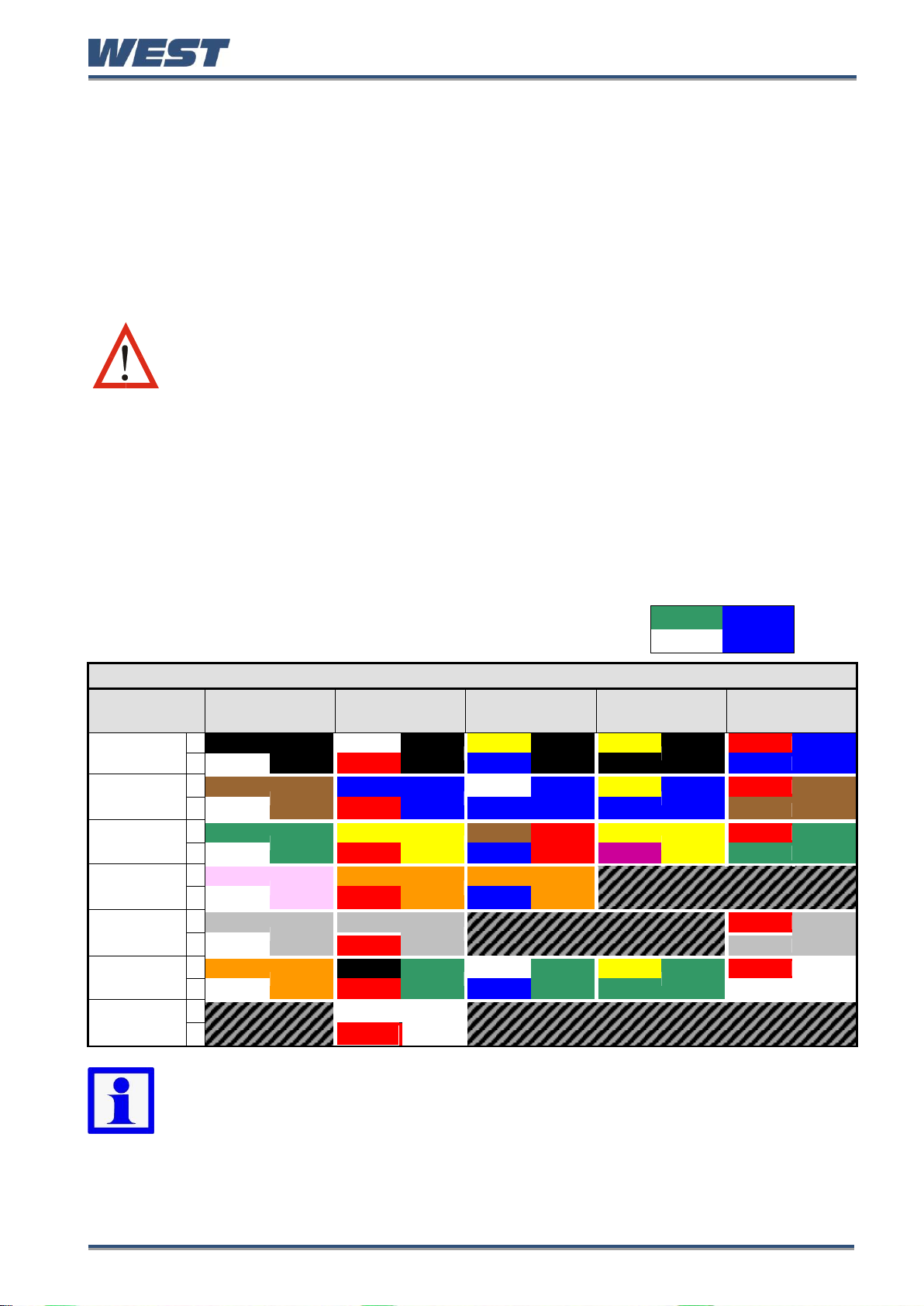
THERMOCOUPLE WIRE COLOUR CHART
Type
International
IEC584-3
USA ANSI
MC 96.1
British
BS1843
French
NFC 42-324
German
DIN 43710
J
+*
Black
Black
White
Black
Yellow
Black
Yellow
Black
Red
Blue
-
White
Red
Blue
Black
Blue
T
+
Brown
Brown
Blue
Blue
White
Blue
Yellow
Blue
Red
Brown
-
White
Red
Blue
Blue
Brown
K
+
Green
Green
Yellow
Yellow
Brown
Red
Yellow
Yellow
Red
Green
-*
White
Red
Blue
Purple
Green
N
+
Pink
Pink
Orange
Orange
Orange
Orange
-
White
Red
Blue
B
+
Grey
Grey
Grey
Grey
Red
Grey
-
White
Red
Grey
R & S
+
Orange
Orange
Black
Green
White
Green
Yellow
Green
Red
White
-
White
Red
Blue
Green
White
C (W5)
+
White
White
-
Red
Note: * = Wire is magnetic – a magnet can be used to assist with correctly
identifying the type and polarity of the conductors
+ Wire
Sheath
- Wire
Sensor Placement (Thermocouple or RTD)
If a temperature probe is to be subjected to corrosive or abrasive conditions, it must be
protected by an appropriate thermowell.
Probes must be positioned to reflect the true process temperature:
1. In a liquid media - the most agitated area
2. In air - the best circulated area
For a two wire RTD, a wire link should be used in place of the third wire (see the wiring
section for details). Two wire RTDs should only be used with lead lengths less than 3 metres.
Use of three wire RTDs is strongly recommended to reduce errors do to lead resistance.
Thermocouple Wire Identification
The different thermocouple types are identified by their wires colour, and where possible, the
outer insulation as well. There are several standards in use throughout the world, but most
regions now use the International IEC584-3 standard.
The table below shows the wire and sheath colours used for most
common thermocouple types. The format used in this table is:
Pro-EC44 Product Manual - 59540-1 October 2013 Page 11
Page 19

Pro-EC44 2-Loop Graphical Profile Controller & Recorder
CAUTION: Installation should be only performed by technically competent
personnel. It is the responsibility of the installing engineer to ensure that
the configuration is safe. Local Regulations regarding electrical installation
& safety must be observed (e.g. US National Electrical Code (NEC) or
Canadian Electrical Code).
CAUTION: This equipment is designed for installation in an enclosure that
provides adequate protection against electric shock. The isolation switch
should be located in close proximity to the unit, in easy reach of the
operator and appropriately marked.
WARNING: This symbol means the equipment is protected throughout by
double insulation. All external circuits connected must provide double
insulation. Failure to comply with the installation instructions may impact
the protection provided by the unit.
Pre-wiring – Cautions, Warnings & Information
WARNING:
TO AVOID ELECTRICAL SHOCK, AC POWER WIRING MUST NOT BE CONNECTED TO THE
SOURCE DISTRIBUTION PANEL UNTIL ALL WIRING PROCEDURES ARE COMPLETED.
CHECK THE INFORMATION LABEL ON THE CASE TO DETERMINE THE CORRECT
VOLTAGE BEFORE CONNECTING TO A LIVE SUPPLY.
Pro-EC44 Product Manual - 59540-1 October 2013 Page 12
Page 20
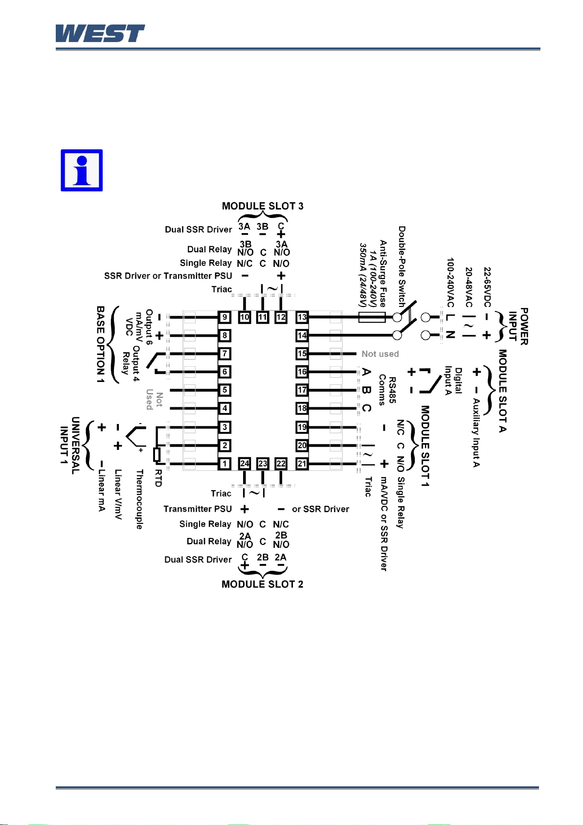
Connections and Wiring
Note: The wiring diagram below shows all possible combinations to the main
connections (numbered 1 to 24) in the centre of the case rear. The actual
connections required depends upon the features and modules fitted.
Central Terminal Connections
Pro-EC44 2-Loop Graphical Profile Controller & Recorder
.
Figure 7. Central Terminals 1 to 24
WARNING:
CHECK THE INFORMATION LABEL ON THE CASE TO DETERMINE THE CORRECT VOLTAGE
BEFORE CONNECTING TO A LIVE SUPPLY.
Pro-EC44 Product Manual - 59540-1 October 2013 Page 13
Page 21
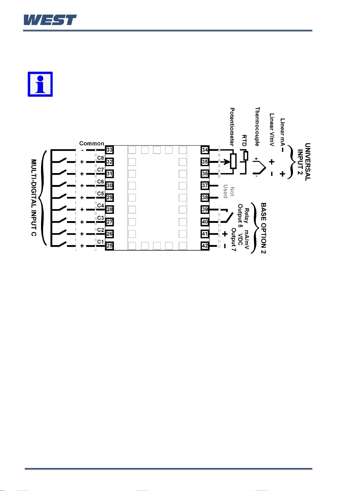
Outer Terminal Connections
Note: The wiring diagram below shows the Central Terminals (numbered 25 to
42) at the sides of the case rear. Connections for the 2nd Input, Base Option 2
and Digital Input C are shown. The actual connections required depends upon
the features and modules fitted.
Pro-EC44 2-Loop Graphical Profile Controller & Recorder
Figure 8. Outer Terminals 25 to 42
Pro-EC44 Product Manual - 59540-1 October 2013 Page 14
Page 22
Pro-EC44 2-Loop Graphical Profile Controller & Recorder
CAUTION: This equipment is designed for installation in an enclosure that
provides adequate protection against electric shock. An isolation switch
should be located in close proximity to the unit, in easy reach of the
operator and appropriately marked.
Power Connections
WARNING:
CHECK THE INFORMATION LABEL ON THE CASE TO DETERMINE THE CORRECT VOLTAGE
BEFORE CONNECTING TO A LIVE SUPPLY.
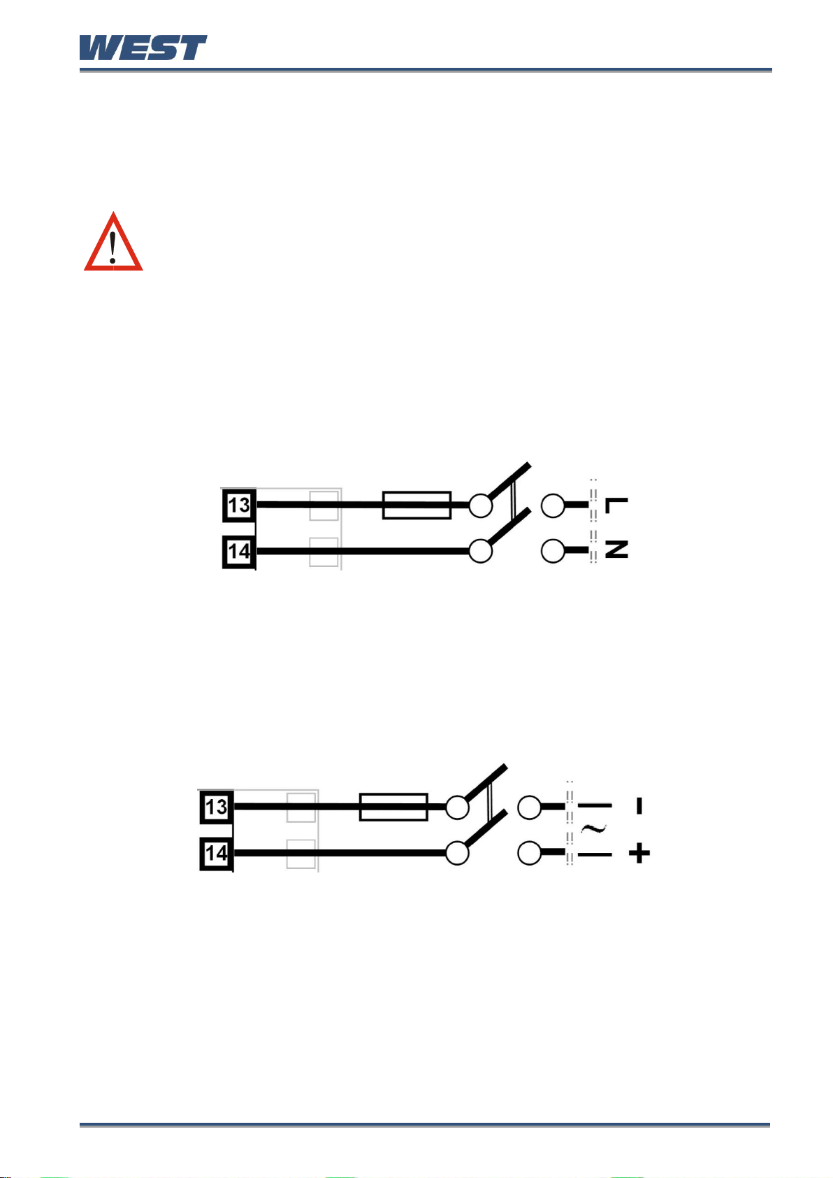
Power Connections - Mains Powered Instruments
Mains powered instruments operate from a 100 to 240V (±10%) 50/60Hz supply. Power
consumption is 20VA. Connect the line and neutral as illustrated via a UL listed fuse type:
250V AC 1Amp anti-surge and a two-pole IEC60947-1 & IEC60947-3 compliant isolation
switch / circuit breaker located within easy reach of the operator and appropriately marked.
If relays switch mains voltage this should be separate from the instruments mains supply.
Figure 9. Mains Power Connections
Power Connections - 24/48V AC/DC Powered Instruments
24/48V AD/DC powered instruments will operate from a 20 to 48V AC or 22 to 55V DC
supply. AC power consumption is 15VA max, DC power consumption is 12 watts max.
Connection should be via a UL listed fuse type: 65v dc 350mAamp anti-surge and a two-pole
IEC60947-1 & IEC60947-3 compliant isolation switch / circuit breaker located within easy
reach of the operator and appropriately marked.
Figure 10. 24/48V AC/DC Power Connections
Pro-EC44 Product Manual - 59540-1 October 2013 Page 15
Page 23
Pro-EC44 2-Loop Graphical Profile Controller & Recorder
Universal Input 1 Connections
Universal Input 1 is present on all models. This input is normally used for the measured
variable signal from a process to be controlled. It can be connected to thermocouples;
resistance temperature detectors; analogue mA; mV or V DC signals. The input settings are
in the Input 1 Configuration sub-menu. Connections for the various types are shown below.
Ensure that the signal is correctly connected, paying particular attention to the polarity.
Universal Input 1 Connections - Thermocouple (T/C)
Supported thermocouple types & ranges are listed in the input specifications section on page
245. Only use the correct thermocouple wire or compensating cable from the sensor to the
instrument terminals avoiding joints in the cable if possible. Where joints are made, special
thermocouple connectors must be used. Failure to use the correct wire type and connectors
will lead to inaccurate readings. Ensure correct polarity of the wires by cross-referencing the
colours with the thermocouple reference table above.
Figure 11. Input 1 - Thermocouple Connections
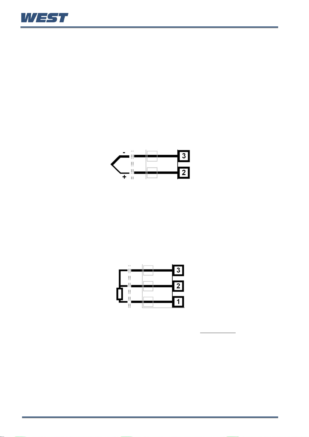
Universal Input 1 Connections – PT100 / NI120 (RTD) input
The inputs supports two types of RTD. PT100 (platinum sensor, 100Ω at 0°C). For three wire
RTDs, connect the resistive leg and the common legs of the RTD as illustrated. For a two
wire RTD a wire link should be fitted across terminals 2 & 3 (in place of the third wire). Two
wire RTDs should only be used when the leads are less than 3 metres long. Avoid cable
joints.
Figure 12. Input 1 - RTD Connections
Four wire RTDs can be used, provided that the fourth wire is left unconnected. This wire
should be cut short or tied back so that it cannot contact any of the terminals on the rear of
the instrument.
Pro-EC44 Product Manual - 59540-1 October 2013 Page 16
Page 24
Pro-EC44 2-Loop Graphical Profile Controller & Recorder
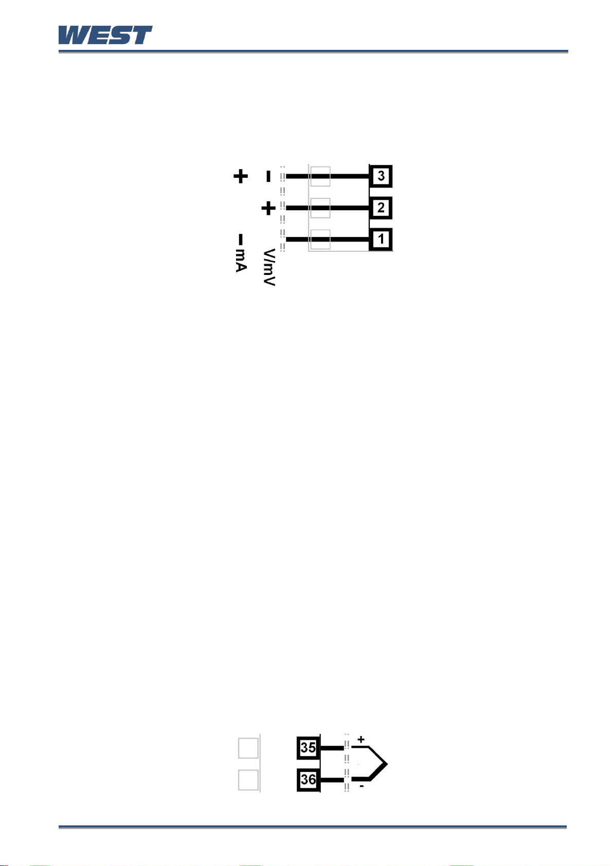
Universal Input 1 Connections - Linear Volt, mV or mA input
The input supports the following linear/analogue signals: 0 to 50mV; 10 to 50mV; 0 to 5V; 1
to 5V; 0 to 10V; 2 to 10V; 0 to 20mV; 4 to 20mA from any suitable source. Voltage & millivolt
signals are connected to terminals 2 & 3, milliamp signals are connected to 1 & 3. Carefully
observe the position & polarity of the connections.
Figure 13. Input 1 - DC Volt, mV & mA Connections
Universal / Auxiliary Input 2 Connections
An Auxiliary Input 2 option is fitted to some models. This can connect to a potentiometer;
analogue mA; mV or V DC signal for a remote setpoint input signal, or for flow/valve position
feedback information.
Alternatively, a second Universal Input 2 option may be fitted. In addition to the remote
setpoint input signal or feedback information possible with the auxiliary input, the 2nd
Universal Input can be used as a second process control loop for two control loops, or used
in conjunction with input one in more complex single control loops. Universal Input 2 can be
connected to thermocouples; resistance temperature detectors; potentiometers; analogue
mA; mV or V DC signals.
The settings are in the Input 2 Configuration sub-menu. Connections for the various types
are shown below. Ensure that the signal is correctly connected, paying particular attention to
the polarity.
Universal Input 2 Connections - Thermocouple (T/C)
The optional 2nd universal input, supports various thermocouple types. Supported types &
ranges are listed in the input specifications section on page 245.
Only use the correct thermocouple wire or compensating cable from the sensor to the
instrument terminals avoiding joints in the cable if possible. Where joints are made, special
thermocouple connectors must be used. Failure to use the correct wire type and connectors
will lead to inaccurate readings. Ensure correct polarity of the wires by cross-referencing the
colours with a thermocouple reference table.
Figure 14. Input 2 - Thermocouple Connections
Pro-EC44 Product Manual - 59540-1 October 2013 Page 17
Page 25
Pro-EC44 2-Loop Graphical Profile Controller & Recorder
Universal Input 2 Connections – PT100 / NI120 (RTD) input
The optional 2nd universal input, supports two types of RTD. PT100 (platinum sensor, 100Ω
at 0°C). For three wire RTDs, connect the resistive leg and the common legs of the RTD as
illustrated. For a two wire RTD a wire link should be fitted across terminals 35 & 36 (in place
of the third wire). Two wire RTDs should only be used when the leads are less than 3 metres
long. If possible, avoid cable joints.
Figure 15. Input 2 - RTD Connections
Four wire RTDs can be used, provided that the fourth wire is left unconnected. This wire
should be cut short or tied back so that it cannot contact any of the terminals on the rear of
the instrument.
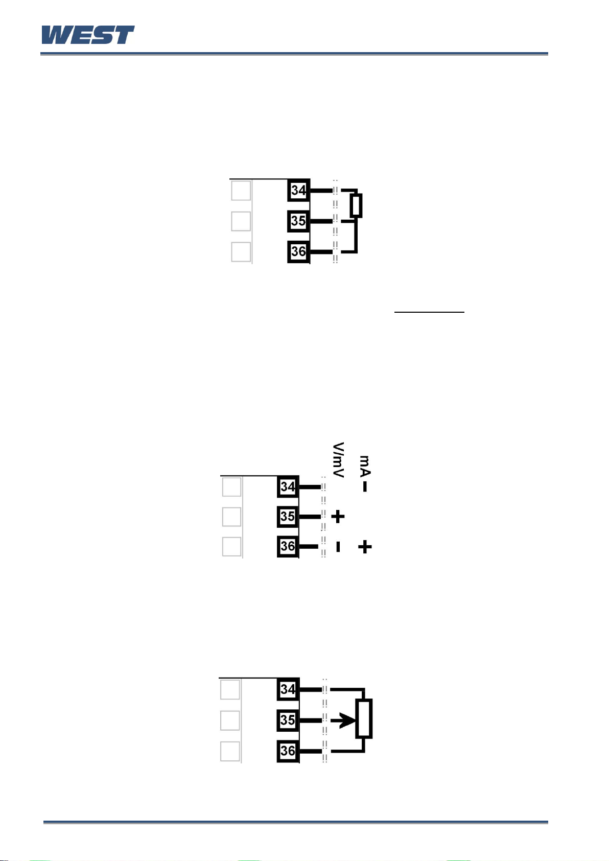
Universal / Auxiliary Input 2 Connections - Linear Volt, mV or mA input
The optional auxiliary or 2nd universal input supports the following linear/analogue signals: 0
to 50mV; 10 to 50mV; 0 to 5V; 1 to 5V; 0 to 10V; 2 to 10V; 0 to 20mV; 4 to 20mA from any
suitable source. Voltage & millivolt signals are connected to terminals 2 & 3, milliamp signals
are connected to 1 & 3. Carefully observe the polarity of the connections.
Figure 16. Input 2 - DC Volt, mV & mA Connections
Universal / Auxiliary Input 2 Connections – Potentiometer
The optional auxiliary or 2nd universal input, the terminals detailed below can be used to
connect a feedback potentiometer. Minimum potentiometer resistance is ≥100Ω.
Figure 17. Input 2 - Potentiometer Connections
Pro-EC44 Product Manual - 59540-1 October 2013 Page 18
Page 26
Pro-EC44 2-Loop Graphical Profile Controller & Recorder
Base Option 1
Base Option 1 provides one or two factory fitted outputs. A relay designated as Output 4 is
fitted on all models, and an optional linear mA/V DC designated as Output 6. Base options
cannot be added after manufacture. The functions of outputs 4 & 6 are set in the Output
Configuration sub-menu. Connect as illustrated below.
Base Option 1 Relay Output 4
Present on all instruments, Output 4 is a SPST relay, rated at 2 amps at 240 VAC resistive. If
it is used to switch mains voltages, the supply should be separate from the instrument supply
and should be correctly switched and fused.
Figure 18. Relay Output 4 Connections
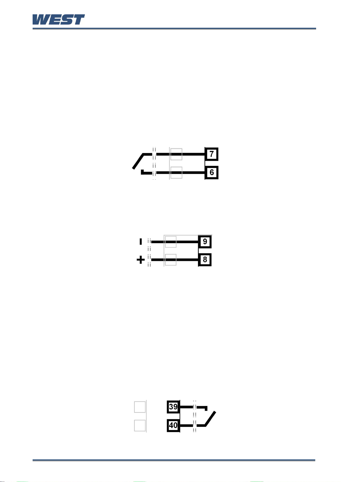
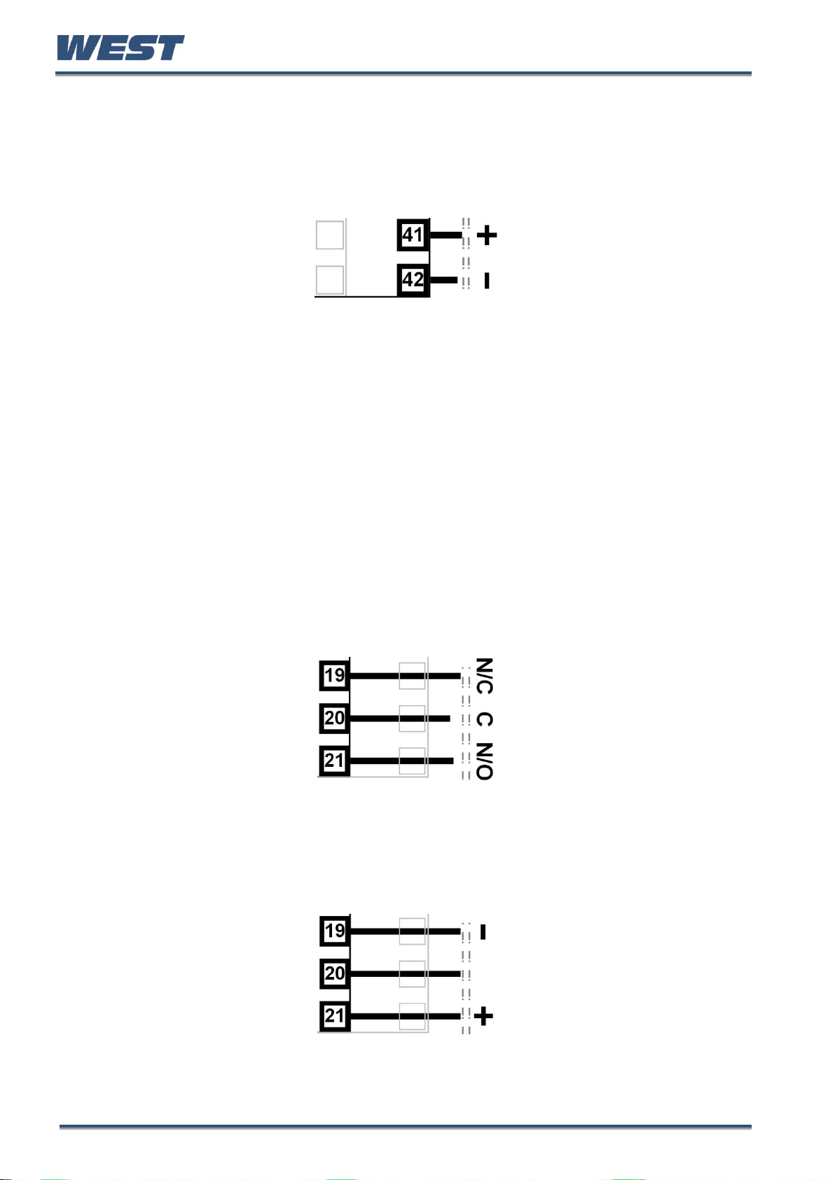
Base Option 1 Linear Output 6
Part of base option 1, Output 6 is an optional linear mV/V DC analogue output. The type &
range are selectable from 0 to 5, 0 to 10, 2 to 10V & 0 to 20 or 4 to 20mA.
Figure 19. Linear Output 6 Connections
Base Option 2
Base Option 2 provides one or two factory fitted outputs. An optional relay designated as
Output 5, and an optional linear mA/V DC designated as Output 7. Base options cannot be
added after manufacture. The functions of outputs 5 & 7 are set in the Output Configuration
sub-menu. Connect as illustrated below.
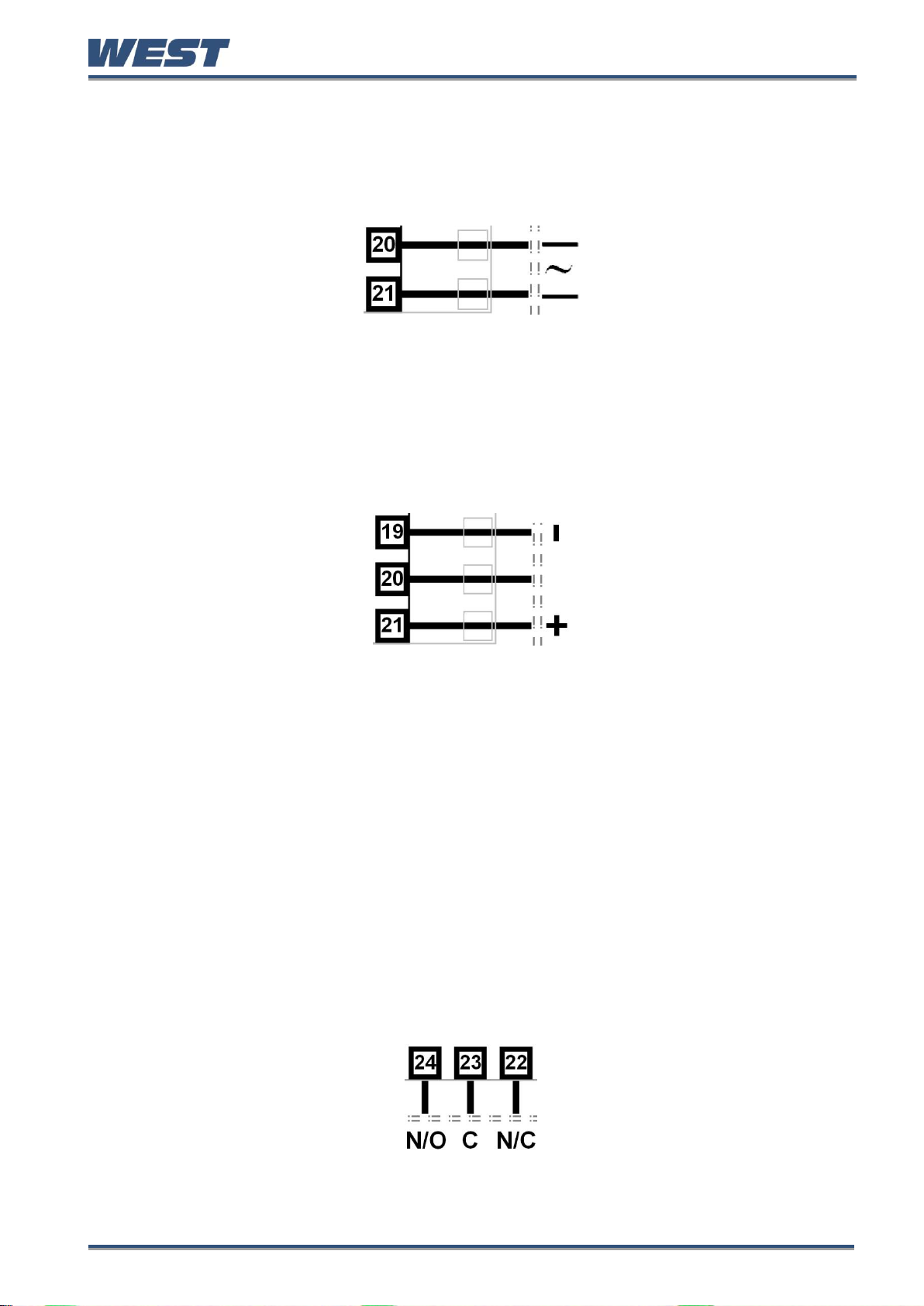
Base Option 2 Relay Output 5
Part of base option 2, Output 5 is a SPST relay, rated at 2 amps at 240 VAC resistive. If it is
used to switch mains voltages, the supply should be separate from the instrument supply and
should be correctly switched and fused.
Figure 20. Relay Output 5 Connections
Pro-EC44 Product Manual - 59540-1 October 2013 Page 19
Page 27
Pro-EC44 2-Loop Graphical Profile Controller & Recorder
Base Option 2 Linear Output 7
Part of base option 2, Output 7 is an optional linear mV/V DC analogue output. The type &
range are selectable from 0 to 5, 0 to 10, 2 to 10V & 0 to 20 or 4 to 20mA.
.
Figure 21. Linear Output 7 Connections
Plug-in Module Slot 1 Connections
A selection of plug-in modules are available for Module Slot 1. They can be fitted during
manufacture, or purchased and fitted later by the user. Modules in slot 1 are designated
Output 1. They are not interchangeable with those in slot 2 or 3. Their function is set in the
Output Configuration sub-menu. Connect as illustrated below.
Plug-in Module Slot 1 – Single Relay Output Module
If fitted with a single relay output module, connect as shown. The relay contacts are SPDT
and rated at 2 amps resistive, 240 VAC. If it is used to switch mains voltages, the supply
should be separate from the instrument supply and should be correctly switched and fused.
Figure 22. Plug-in Module Slot 1 – Single Relay Module
Plug-in Module Slot 1 – Single SSR Driver Output Module
If fitted with a single SSR Driver output module, connect as shown. The 10V DC pulse signal
(load ≥500 ohms) is isolated from all inputs/outputs except other SSR drivers.
Figure 23. Plug-in Module Slot 1 – Single SSR Driver Module
Pro-EC44 Product Manual - 59540-1 October 2013 Page 20
Page 28
Pro-EC44 2-Loop Graphical Profile Controller & Recorder
Plug-in Module Slot 1 - Triac Output Module
If fitted with a triac output module, connect as shown. This output is rated at 0.01 to 1 amp @
280V AC 50/60Hz. Isolated from all other inputs and outputs. A snubber should be fitted
across inductive loads to ensure reliable switch off of the Triac.
Figure 24. Plug-in Module Slot 1 - Triac Module
Plug-in Module Slot 1 - Linear Voltage or mADC Output module
If fitted with a DC linear output module, connect as shown. Output type & range are
selectable from 0 to 5, 0 to 10, 2 to 10V & 0 to 20 or 4 to 20mA. Isolated from all other inputs
and outputs.
Figure 25. Plug-in Module Slot 1 - Linear Voltage & mADC Module
Plug-in module slot 2 Connections
A selection of plug-in modules are available for Module Slot 2. They are interchangeable with
slot 3, but not slot 1.They can be fitted during manufacture, or purchased and fitted later by
the user. Modules in slot 2 are designated Output 2, and for dual modules Output 2A and 2B.
Their functions are set in the Output Configuration sub-menu. Connect as illustrated below.
Plug-in Module Slot 2 – Single Relay Output Module
If fitted with a single relay output module, connect as shown. The relay contacts are SPDT
and rated at 2 amps resistive, 240 VAC. If it is used to switch mains voltages, the supply
should be separate from the instrument supply and should be correctly switched and fused.
Figure 26. Plug-in Module Slot 2 – Single Relay Module
Pro-EC44 Product Manual - 59540-1 October 2013 Page 21
Page 29
Pro-EC44 2-Loop Graphical Profile Controller & Recorder
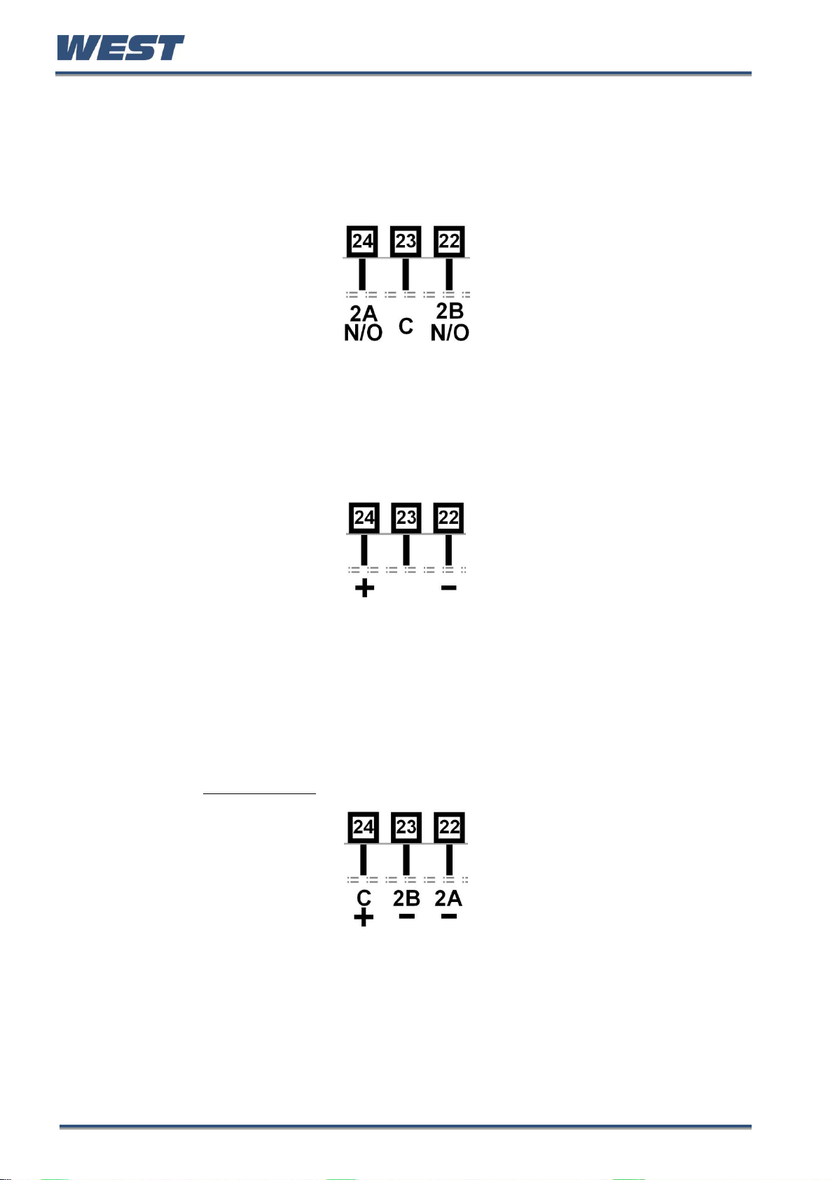
Plug-in Module Slot 2 - Dual Relay Output Module
If fitted with a dual relay output module, connect as shown. This module has two independent
SPST relays for outputs 2A and 2B, with a shared common terminal. The contacts are rated
at 2 amp resistive 240 VAC. If used to switch mains voltages, the supply should be separate
from the instruments mains supply and the contacts should be correctly switched and fused.
Figure 27. Plug-in Module Slot 2 - Dual Relay Module
Plug-in Module Slot 2 – Single SSR Driver Output Module
If fitted with a single SSR Driver output module, connect as shown. The 10V DC pulse signal
(load ≥500 ohms) is isolated from all inputs/outputs except other SSR drivers.
Figure 28. Plug-in Module Slot 2 – Single SSR Driver Module
Plug-in Module Slot 2 – Dual SSR Driver Output Module
If fitted with a dual SSR Driver output module, the two solid-state relay driver outputs are
designated as Output 2A and 2B. The outputs are 10V DC pulse signals, (load ≥500 ohms).
They are isolated from all inputs/output except other SSR driver outputs. Connect as shown
making note of the shared positive common terminal.
Figure 29. Plug-in Module Slot 2 – Dual SSR Driver Module
Pro-EC44 Product Manual - 59540-1 October 2013 Page 22
Page 30
Pro-EC44 2-Loop Graphical Profile Controller & Recorder
Plug-in Module Slot 2 - Triac Output Module
If fitted with a Triac output module, connect as shown. This output is rated at 0.01 to 1 amp
@ 280V AC 50/60Hz. Isolated from all other inputs and outputs. A snubber should be fitted
across inductive loads to ensure reliable switch off of the Triac.
Figure 30. Plug-in Module Slot 2 - Triac Module
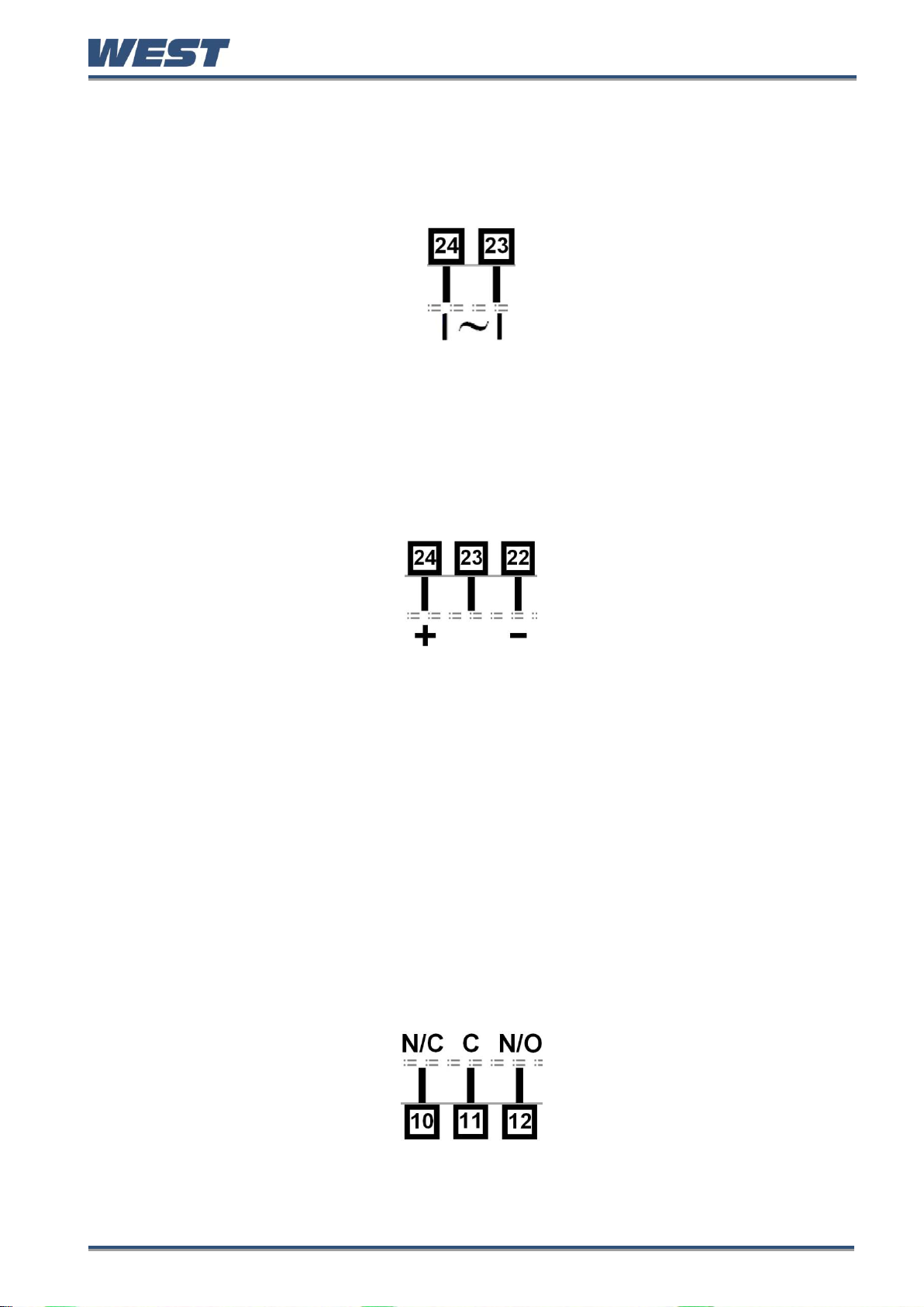
Plug-in Module Slot 2 - Transmitter Power Supply Module
If fitted with a transmitter power supply module (TxPSU), connect as shown. The output is a
24V nominal (unregulated, 19 to 28V DC), supply at 22mA max. Only one TxPSU is
supported, do not fit in slot 2 if one is already fitted in slot 3.
Figure 31. Plug-in Module Slot 2 - Transmitter Power Supply Module
Plug-in Slot 3 Connections
A selection of plug-in modules are available for Module Slot 3. They are interchangeable with
slot 2, but not slot 1.They can be fitted during manufacture, or purchased and fitted later by
the user. Modules in slot 3 are designated Output 3, and for dual modules Output 3A and 3B.
Their functions are set in the Output Configuration sub-menu. Connect as illustrated below.
Plug-in Module Slot 3 – Single Relay Output Module
If fitted with a single relay output module, connect as shown. The relay contacts are SPDT
and rated at 2 amps resistive, 240 VAC. If it is used to switch mains voltages, the supply
should be separate from the instrument supply and should be correctly switched and fused.
Figure 32. Plug-in Module Slot 3 – Single Relay Module
Pro-EC44 Product Manual - 59540-1 October 2013 Page 23
Page 31
Pro-EC44 2-Loop Graphical Profile Controller & Recorder
Plug-in Module Slot 3 - Dual Relay Output Module
If fitted with a dual relay output module, connect as shown. This module has two independent
SPST relays for outputs 3A and 3B, with a shared common terminal. The contacts are rated
at 2 amp resistive 240 VAC. If used to switch mains voltages, the supply should be separate
from the instruments mains supply and the contacts should be correctly switched and fused.
Figure 33. Plug-in Module Slot 3 - Dual Relay Module
Plug-in Module Slot 3 – Single SSR Driver Output Module
If fitted with a single SSR Driver output module, connect as shown. The 10V DC pulse signal
(load ≥500 ohms) is isolated from all inputs/outputs except other SSR drivers.
Figure 34. Plug-in Module Slot 3 – Single SSR Driver Module
Plug-in Module Slot 3 – Dual SSR Driver Output Module
If fitted with a dual SSR Driver output module, the two solid-state relay driver outputs are
designated as Output 3A and 3B. The outputs are 10V DC pulse signals, (load ≥500 ohms).
They are isolated from all inputs/output except other SSR driver outputs. Connect as shown
making note of the shared positive common terminal.
Figure 35. Plug-in Module Slot 3 – Dual SSR Driver Module
Pro-EC44 Product Manual - 59540-1 October 2013 Page 24
Page 32

Pro-EC44 2-Loop Graphical Profile Controller & Recorder
Plug-in Module Slot 3 - Triac Output Module
If fitted with a Triac output module, connect as shown. This output is rated at 0.01 to 1 amp
@ 280V AC 50/60Hz. Isolated from all other inputs and outputs. A snubber should be fitted
across inductive loads to ensure reliable switch off of the Triac.
Figure 36. Plug-in Module Slot 3 - Triac Module
Plug-in Module Slot 3 - Transmitter Power Supply Module
If fitted with a transmitter power supply module (TxPSU), connect as shown. The output is a
24V nominal (unregulated, 19 to 28V DC), supply at 22mA max. Only one TxPSU is
supported, do not fit in slot 3 if one is already fitted in slot 2.
.
Figure 37. Plug-in Module Slot 3 - Transmitter Power Supply Module
Plug-in Slot A Connections
A selection of plug-in modules are available for Module Slot A. They can be fitted during
manufacture, or purchased and fitted later by the user. Depending on their functions, they
are setup Input or Communications configuration sub-menus. Connect as illustrated below.
Plug-in Module Slot A – Basic Auxiliary Input Module
If fitted with a basic auxiliary mA/V DC analogue input module, connect as shown. Isolated
from all inputs/outputs. Consider using the 2nd auxiliary input (if available) instead, as this has
additional features and leaves plug-in module slot A free for other modules.
Figure 38. Plug-in Module Slot A – Basic Auxiliary Input Module
Pro-EC44 Product Manual - 59540-1 October 2013 Page 25
Page 33

Pro-EC44 2-Loop Graphical Profile Controller & Recorder
CAUTION: External computing devices connected to the communications
port should comply with the standard, UL 60950.
Plug-in Module Slot A - Ethernet Communications Module
If fitted with the Ethernet communication module, the communications protocol available is
Modbus TCP. Isolated from all inputs/outputs. If necessary, cut out the removable panel to
access the RJ45 connector through the top of the case. No rear connections are required.
Plug-in Module Slot A - RS485 Serial Communications Module
If fitted with the RS485 serial communication module, the protocol used is Modbus RTU.
Isolated from all inputs/outputs. Carefully observe the polarity of the A (Rx/Tx +ve) and B
(Rx/Tx -ve) connections.
Figure 39. Plug-in Module Slot A – RS485 Serial Communications Module
Plug-in Module Slot A – Single Digital Input Module
If a digital input module is fitted, it provides a fully isolated input that is held high via a pull-up
resistor. The input can be connected to either to voltage free contacts (e.g. from a switch), or
a TTL compatible signal.
Logic High = Open contacts (>5000Ω) or 2 to 24VDC signal.
Logic Low = Closed contacts (<50Ω) or -0.6 to +0.8VDC signal.. Connect as shown.
Figure 40. Plug-in Module Slot A – Digital Input A Module
Pro-EC44 Product Manual - 59540-1 October 2013 Page 26
Page 34

Pro-EC44 2-Loop Graphical Profile Controller & Recorder
Option C Connections
Option C offers a factory fitted multiple digital input option. The board also accommodates
the USB port if that is option is fitted. The USB port does not have connections on the rear
terminal, it is accessed via the front panel.
Option C Connections – Multiple Digital Input Module
If the Multiple Digital Input option is fitted, the connections are as illustrated. The 8 optoisolated inputs each have a positive input terminal and share a common negative terminal.
The inputs are held high with internal pull-up resistors, so may be connected to either voltage
free contacts (e.g. from a switch), or TTL compatible signals:
Logic High = Open contacts (>5000Ω) or 2 to 24VDC signal.
Logic Low = Closed contacts (<50Ω) or -0.6 to +0.8VDC signal.
Figure 41. Option C - Multiple Digital Inputs C1 to C8
Pro-EC44 Product Manual - 59540-1 October 2013 Page 27
Page 35

Pro-EC44 2-Loop Graphical Profile Controller & Recorder
CAUTION: The windings of a valve motor effectively form an
autotransformer. This has a voltage doubling effect when power is applied
to either the Open or Close terminal, causing twice the supplied voltage at
the other terminal. For this reason, switching devices directly connected to
the valve motor must only be used up to half of their rated voltage. The
maximum motor voltage when using the internal relays/triacs is therefore
120V unless interposing relays are used. Interposing relays or other devices
used to control the valve must themselves be rated for twice the motor
supply voltage.
Open Valve Winding
Close Valve Winding
Valve Common
“OPEN” RELAY
N/O
C
N/C
N/C C N/O
“CLOSE” RELAY
N/C C N/O
120VAC SUPPLY
2 x 120V = 240V
120V
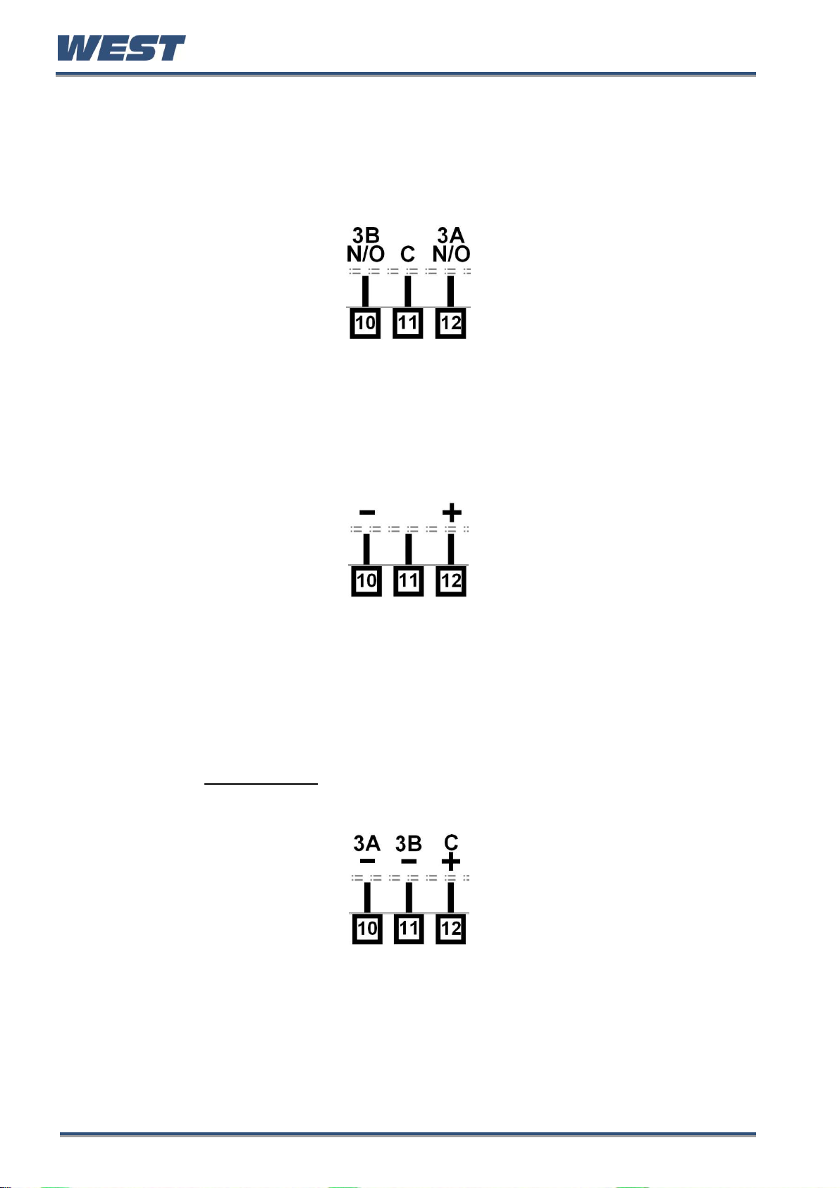
Special Wiring Considerations for Valve Motor Control
Valve Motor Drive (VMD) controllers require two identical outputs to be assigned to position
the valve. One to open and one to close the valve. These outputs can be two single relays,
two triacs, two SSR drivers or one dual relay, but it is recommended to use two single relays
(SPDT change-over contacts), and to interlock the relay wiring as shown. This prevents both
motor windings from being driven at the same time, even under fault conditions.
Switching actuators directly connected to the valve motor must only be used up to half of
their rated voltage (see CAUTION below). The internal relay and triac outputs are rated at
240VAC, so the maximum motor voltage when using them in this way is therefore 120V
unless interposing relays are used. Interposing relays or other devices used to control the
valve must themselves be rated for twice the motor supply voltage.
Figure 42. Interlocking of Valve Motor Drive Relays
Pro-EC44 Product Manual - 59540-1 October 2013 Page 28
Page 36

Pro-EC44 2-Loop Graphical Profile Controller & Recorder
CAUTION: Ensure safe wiring practices have been followed. When powering
up for the first time, disconnect the output connections. The instrument
must be powered from a supply according to the wiring label on the side of
the unit. The supply will be either 100 to 240V AC, or 24/48V AC/DC
powered. Check carefully the supply voltage and connections before
applying power
5 Powering Up
Powering Up Procedure
At power up, a self-test procedure is automatically started, during which a splash screen is
displayed and the LED indicators are lit. At the first power up from new, a Setup Wizard runs
to assist configuration of basic applications (refer to the Setup Wizard section on page 43).
At all other times, the instrument returns to the normal operation mode once the self-test
procedure is complete.
Front Panel Overview
The illustration below shows an instrument fitted with the optional USB socket located to the
right of the four keypad buttons. Clean the front panel by washing with warm soapy water
and dry immediately. If the USB option is fitted, close the port cover before cleaning.
Figure 43. A Typical Front Panel
Display
The instrument has a 160 x 80 pixel monochrome graphical display with dual colour
(red/green) backlight. The main display typically shows the process variables, setpoints,
power / deviation bar graphs or graphical trends during normal operation. There are recorder
and profile status screen. The top line of the display has labels for the 4 LED indicators. If
desired, the backlight colour can be changed to indicate the presence of an active alarm or
latched output. Refer to the Display Configuration section - page 59
Pro-EC44 Product Manual - 59540-1 October 2013 Page 29
Page 37
Pro-EC44 2-Loop Graphical Profile Controller & Recorder
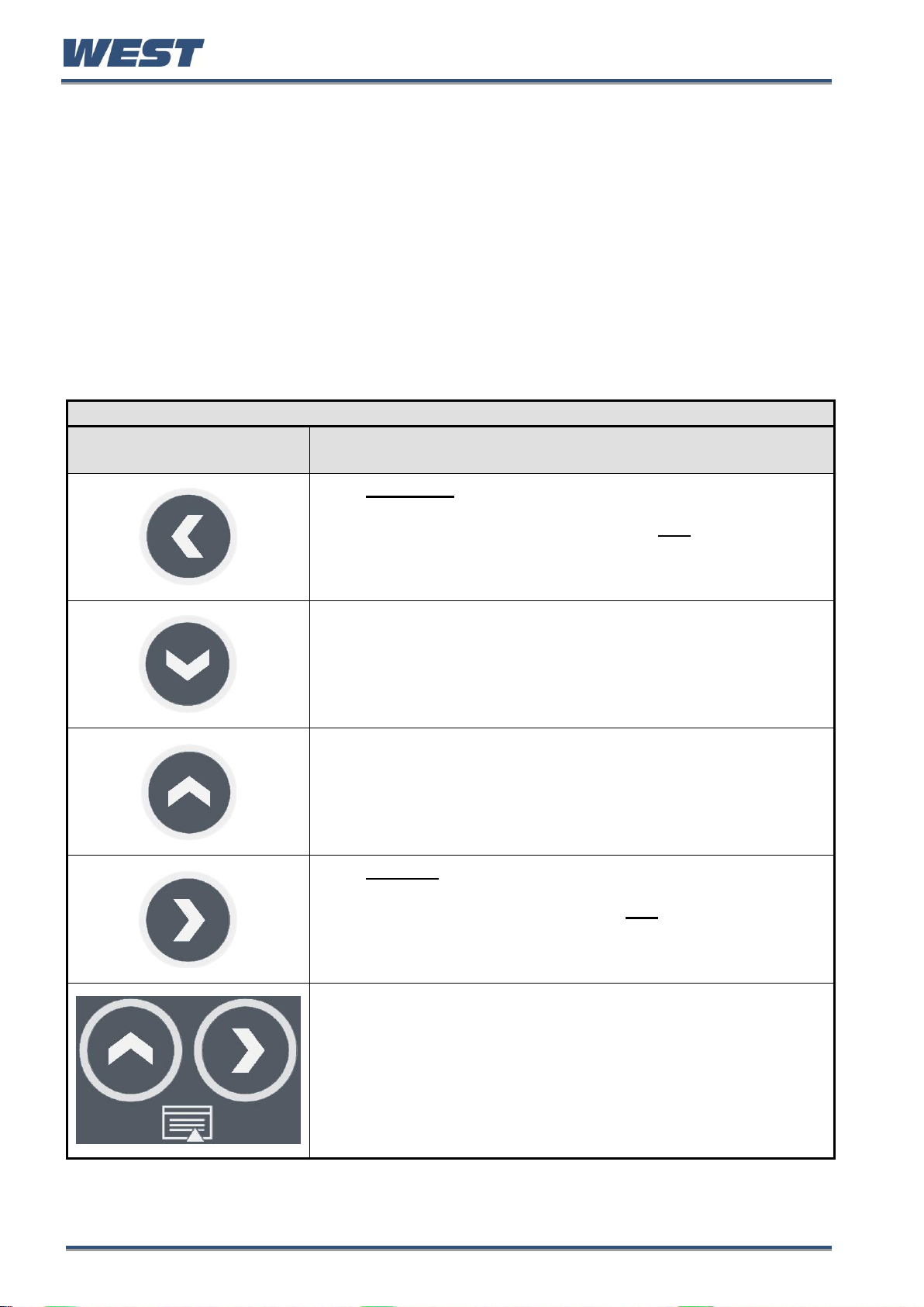
Keypad Button Functions
Button
Function
Moves backwards to the previous parameter or screen in the
current mode. Holding this key down for more than 1 second skips
immediately to the previous screen accepting ALL values as shown.
CAUTION: If editing a parameter, ensure that the current
(highlighted) parameter value is correct before pressing the key as
this action will update and store the value displayed.
In menus and configuration choice screens, this key moves to the
next item on the list.
Editable values can be decreased by pressing this key. Holding the
key down speeds up the change.
In Trend views this key moves the Cursor Line back through the
stored data points
In menus and configuration choice screens, this key moves to the
previous item on the list.
Editable values can be increased by pressing this key. Holding the
key down speeds up the change.
In Trend views this key moves the Cursor Line forward through the
stored data points
Moves forwards to the next parameter or screen in the current
mode. Holding this key down for more than 1 second skips
immediately to the next screen accepting ALL values as shown.
CAUTION: If editing a parameter, ensure that the current
(highlighted) parameter value is correct before pressing the key as
this action will update and store the value displayed.
Pressing the U key while holding down the R key causes the
instrument to move up one menu level. From Operation Mode and in
most menus, this will result in entry to the Main Menu.
From sub-menus, it is necessary to carry out this sequence more
than once to reach the main menu.
CAUTION: If editing a parameter, ensure that the current
(highlighted) parameter value is correct before pressing the key as
this action will update and store the value displayed.
LED Functions
There are four red LEDs that by default indicate the status of the primary & secondary
outputs, automatic tuning and alarm status. The top line of the graphical display has four
labels for LED indicators. The function of these LEDs and their display labels can be
changed using the PC configuration software. The information in this manual assumes
standard functions for these LEDs.
Keypad Functions & Navigation
Each instrument has four keypad switches, which are used to navigate through the user
menus and adjust the parameter values. In configuration screens, a context sensitive
scrolling help text is displayed that guides the user about the function of the keys.
Pro-EC44 Product Manual - 59540-1 October 2013 Page 30
Page 38

Pro-EC44 2-Loop Graphical Profile Controller & Recorder
CAUTION: Do not continue using the product until the the error is resolved.
CAUTION: Correct the signal/wiring problem to continue normal operation.
CAUTION: Perform a full base calibration of the input before continuing
normal operation (see page 72). If the problem persists, return the
instrument for servicing.
6 Messages & Error Indications
Plug-in Module Problems
If an invalid or unknown module is detected in one of the plug-in module slots during the
power-up self-test, the message “Fault Found, Press R, for details” is shown. This is
followed by “Replace faulty module in Module Slot n, Press R,” (where n is the faulty slot
location). The Service Contact information is displayed next showing details of who to
contact if a fault persists
Replace the module in slot “n”. If this does not solve the problem, return the instrument for
investigation.
Sensor Break Detection
Whenever a problem is detected with a process variable or auxiliary input connection, the
displayed value for that input is replaced with the word “OPEN”; except in Ratio control
where an open input 1 or 2 is shown as “x1-Open” or “x2-Open”. See Redundant Input
(page 83) to protect critical processes from sensor faults.
This may be the result of a failed sensor, a broken connection or an input circuit fault.
In this condition, the control outputs go to the pre-set power value (see Control Configuration
– page 50).
Un-Calibrated Input Detection
The instrument is fully calibrated during manufacture. If a fault occurs and calibration data is
lost, the process input displays are replaced with the word “ERROR” and error is shown
instead of “Calibrated” for effected inputs in Service & Product Information mode.
In this condition, the control outputs go to the pre-set power value (see Control Configuration
– page 50).
PV Over-range or Under-range Indication
If a measured process input value is more than 5% above than the Scaled Input Upper Limit,
its value is replace by the word “HIGH” to indicate that it is out of range.
If a measured process input value is more than 5% below than the Scaled Input Lower Limit,
its value is replaced by the word “LOW” to indicate that it is out of range.
Pro-EC44 Product Manual - 59540-1 October 2013 Page 31
Page 39

Pro-EC44 2-Loop Graphical Profile Controller & Recorder
Auxiliary Input Over-range or Under-range Indication
If the auxiliary Remote Setpoint input is more than 5% above than the Auxiliary Input Upper
Limit, its value is replaced by the word “HIGH” to indicate that it is out of range.
If the auxiliary Remote Setpoint input is more than 5% below than the Auxiliary Input Lower
Limit, its value is replace by the word “LOW” to indicate that it is out of range.
Cascade-Open
“Cascade Open” is shown on the main screen if the internal link has be severed between
cascaded master and slave control loops. This mode should only be used for diagnostics and
slave tuning. Close the cascade for proper operation. Refer to the Cascade Control section
(page 78) for more information.
Profile Not Valid
If the user attempts to run a profile that would take the setpoint beyond the current setpoint
limits, the profile will not run and the message “Profile Not Valid” is displayed at the bottom
of the profile status screen.
USB Data Transfer Failure message
If the instrument cannot successfully write to the USB memory stick, the message “Data
Transfer Failure” will be displayed. Check that there is adequate disk space on the memory
stick, then retry.
If the instrument cannot successfully read data from the USB memory stick, the message
“Data Transfer Failure” will also appear. Check that this operation would not cause the
maximum number of profiles and/or segments to be exceeded then retry.
Getting Help
First Level Support
If the errors persist or other problems are encountered, refer your supplier for first level
support. This includes help with configuration, tuning, servicing and replacement modules.
Second Level Support
If your supplier is unable to assist or cannot be contacted, check the Service & Product
Information screen on the main menu for details of who to contact.
Third Level Support
If further assistance is required, contact the nearest company from those listed on the back
page of this manual.
Servicing
If you need to return your instrument for servicing, contact your supplier or check the Service
& Product Information screen on the main menu for instructions for its return.
Pro-EC44 Product Manual - 59540-1 October 2013 Page 32
Page 40

Pro-EC44 2-Loop Graphical Profile Controller & Recorder
Process Type*
Loop 1 / Master
Loop 2 / Slave
(only if 2nd
input fitted)
Control
Configuration:
Control Select
Control
Configuration:
Control Type
Control
Configuration:
Control Select
Control
Configuration:
Control Type
One Loop*
Input 2
Configuration |
Input 2 Usage
= Not Used
Standard PID
Control Select
= Control Standard
Primary Only
Control Type
= Single
Primary / Secondary
Control Type
= Dual
Valve Motor Drive
Control Select
= VMD (TPSC)
Control
7 Application Setup
Before beginning configuration, consider how the controller will be used in your application.
For instance, how many control loops are needed, is cascade or ratio control required, will
the unit control a valve motor, do you need setpoint profiling etc. Consideration should also
be given to the output types, alarms and tuning method.
This section is intended to help with this process, guiding you through the major configuration
settings. Additional information can be found in the relevant sections of this manual, including
the glossary, configuration menus, and dedicated sections for major features. These are
listed in the table of contents.
Pre-commissioning Considerations
An easy Setup Wizard is available for basic applications (see page 43) where the most
commonly required parameters are present for adjustment in turn. The wizard has a sub-set
of the full configuration menu options. For more complex applications where the wizard is not
sufficient, consideration must be given to the following fundamental questions:
If fitted, how will the 2nd input be used?
One loop only (if the 2nd input not fitted or not used in this application)
Two independent control loops (see page 50).
Valve feedback for loop 1 (see page 85Error! Bookmark not defined.).
A “redundant” backup for the 1st input (see page 83).
Cascaded with the first control loop (see page 78).
A reference input for ratio control (see page 81).
How will the instrument physically control the process?
Primary only or primary & secondary control outputs (see page 210).
Direct valve motor drive outputs (see page 84).
The table below shows the main input and control configuration settings for these application
types (see page 45 for the configuration menus).
Pro-EC44 Product Manual - 59540-1 October 2013 Page 33
Page 41

Pro-EC44 2-Loop Graphical Profile Controller & Recorder
Process Type*
Loop 1 / Master
Loop 2 / Slave
(only if 2nd
input fitted)
Control
Configuration:
Control Select
Control
Configuration:
Control Type
Control
Configuration:
Control Select
Control
Configuration:
Control Type
Two Loops*
Input 2
Configuration |
Input 2 Usage
= Standard
Standard PID
Control Select
= Control Standard
Primary Only
Control Type
= Single
Standard PID
Control Select
= Control Standard
Primary Only
Control Type
= Single
Primary / Secondary
Control Type
= Dual
Primary / Secondary
Control Type
= Dual
Valve Motor Drive
Control Select
= VMD (TPSC)
Control
Valve Motor Drive
Control Select
= VMD (TPSC)
Control
+Feedback*
Input 2
Configuration |
Input 2 Usage
= Feedback
Valve Motor Drive
Control Select
= VMD (TPSC)
Control
Redundant*
Input 2
Configuration |
Input 2 Usage
= Redundant
Input
Standard PID
Control Select
= Control Standard
Primary Only
Control Type
= Single
Primary / Secondary
Control Type
= Dual
Valve Motor Drive
Control Select
= VMD (TPSC)
Control
Cascade*
Input 2
Configuration |
Input 2 Usage
= Standard
AND
Loop 1 / Master
Configuration |
Control Mode
= Cascade
Standard PID
Control Select
= Control Standard
Primary Only
Control Type
= Single
Primary / Secondary
Control Type
= Dual
Valve Motor Drive
Control Select
= VMD (TPSC)
Control
Ratio*
Input 2
Configuration |
Input 2 Usage
= Standard
AND
Loop 1 / Master
Configuration |
Control Mode
= Ratio
Standard PID
Control Select
= Control Standard
Valve Motor Drive
Control Select
= VMD (TPSC)
Control
Which outputs will be used for control, and are alarms or event outputs needed?
Output configuration (see page 56).
Alarms & Profile Events (see page Alarm Types207 & 225).
Pro-EC44 Product Manual - 59540-1 October 2013 Page 34
Page 42

Pro-EC44 2-Loop Graphical Profile Controller & Recorder
CAUTION: Configuration & commissioning must be completed before
proceeding to Operation Mode. It is the responsibility of the installing
engineer to ensure that the configuration is safe.
What are the sources for the setpoints?
Local setpoint(s) only, or a remote setpoint input (see page 216 & 227).
Profile Control (see page 87).
Is Input re-configuration required?
Analogue input calibration & scaling (see page 70).
Digital input functions (see page 75).
Which other features are to be used?
Data Recorder (see page 97).
Serial Communications (see page 109).
USB Interface (see page 96).
Once you have an understanding of your application and how the controller will be used,
continue on to the configuration and use section below.
Pro-EC44 Product Manual - 59540-1 October 2013 Page 35
Page 43

Pro-EC44 2-Loop Graphical Profile Controller & Recorder
CAUTION: Set all Configuration parameters as required before starting
normal operations. It is the responsibility of the installing engineer to
ensure that the configuration is safe for the intended application.
8 Operation and Configuration Menus
This section contains information on all of the controller’s modes and the configuration
menus.
Operation Mode
This is the mode used during normal operation of the instrument. It can be accessed from the
Main Menu, and is the usual mode entered at power-up. The available displays are
dependent upon the features/options fitted and the way in which it has been configured.
The Base screen is the usual screen displayed during operation. It provides “at a glance”
information about the process. The Profile Status screen shows similar information when
using profiles.
Subsequent screens allow the display and selection/adjustment* of the setpoints. From
display configuration, a selection of other parameter screens can be made available for
operator selection/adjustment*. These include: profile control; cascade open/close;
auto/manual control; setpoint ramp rate; setpoint source; control enable; clear latched
outputs; data recording & status trend views. Optional operator mode screens are marked ◘
in the screen lists.
Some screens will persist until the user navigates away, others will ‘time-out’ back to the
base screen.
* If required, all Operation Mode parameters can be made read only (see Display
Configuration on page 59Error! Bookmark not defined.). Otherwise parameters such as
setpoints can be adjusted within their configured limits.
WARNING:
DURING NORMAL USE, THE USER MUST NOT REMOVE THE CONTROLLER FROM ITS
HOUSING OR HAVE UNRESTRICTED ACCESS TO THE REAR TERMINALS, AS THIS WOULD
PROVIDE POTENTIAL CONTACT WITH HAZARDOUS LIVE PARTS.
Navigating and Adjusting Values in Operator Mode
Press R to move forward or L to move backwards through the available screens.
When a displayed value can be adjusted, use D or U to change its value.
The next/previous screen follows the last parameter. If no further changes are needed,
hold down R or L for >1sec to skip straight to the next/previous screen accepting
ALL values shown.
In Trend Views, pressing D or U moves the cursor line back and forward through the
last 240 data points.
Pro-EC44 Product Manual - 59540-1 October 2013 Page 36
Page 44
Pro-EC44 2-Loop Graphical Profile Controller & Recorder
OPERATION MODE SCREEN SEQUENCE
All possible screens are listed below. The sequence shown depends on the configuration and status.
E.g. settings for “Loop 2” only apply if 2nd input is fitted and configured for 2-loop control.
◘ Some screens are only shown if set to do so in Display Configuration.
After 2 minutes without key activity, the most screens revert to the Base Operating Screen. Screens
marked do not revert automatically. They remain displayed until the user navigates away.
Calibration Check Due Warning
If a Calibration Reminder is set and the due date has passed this will be shown at every power up,
and repeated once per day. Press R to acknowledge and continue using the instrument temporarily
without recalibration. Change the due date or disable the reminder to cancel the warning.
This feature is only possible if the recorder is fitted. It is enabled in Input Configuration.
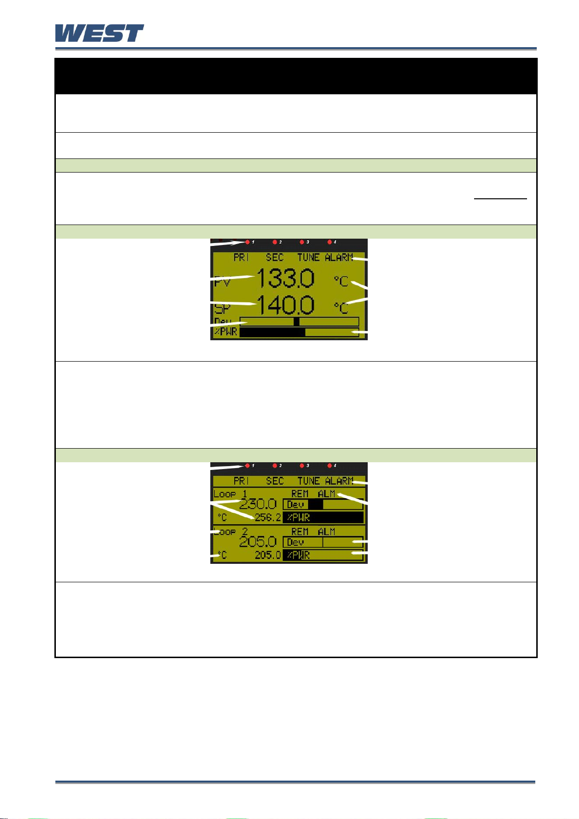
Single Control Loop: Normal Operation
LED Indicators
LED Function Labels
Process Variable Value
Effective Actual Setpoint
Value
Engineering Units
Control Deviation Graph
(scaled ±5% of input span)
Power Graph (0-100% primary,
±100% primary & secondary)
1-LOOP OPERATION
Default LED indicator functions are PRI, SEC, TUNE & ALARM - the functions and their labels can be
altered only with the PC configuration software.
In valve motor drive mode, the power bar-graph is replaced by valve Open / Stop / Close unless the
2nd input is used for position feedback, where it shows 0 to 100% valve position.
In manual mode the effective setpoint is replaced by the %Manual Power and the label “MAN”.
In manual mode with valve motor drive the setpoint is replaced by valve Open / Stop / Close.
If control is disabled the effective setpoint value is replaced by “OFF”.
Two Control Loops: Normal Operation
LED Indicators
LED Function Labels
Process Variable* & Actual
Setpoint Values*
Indicators for Alarm and
Remote Setpoint active*
Loop Description*
Control Deviation (±5% of
span) & Power Graphs*
Engineering Units*
* = in loop 1 & 2 screen area
2-LOOP OPERATION
Default LED indicator functions are PRI 1, PRI 2, TUNE & ALARM - the functions and their labels can
be altered only with the PC configuration software.
In valve motor drive mode, the power bar-graph is replaced by valve Open / Stop / Close.
In manual mode the effective setpoints are replaced by the %Manual Power and the label “MAN”.
In manual mode with valve motor drive the setpoint is replaced by valve Open / Stop / Close.
If control is disabled the effective setpoint value of that loop is replaced by “OFF”.
Pro-EC44 Product Manual - 59540-1 October 2013 Page 37
Page 45

Pro-EC44 2-Loop Graphical Profile Controller & Recorder
Cascade Control: Normal Operation
LED Indicators
LED Function Labels
Cascade Status
Master Process Value
Slave Process Value
Master Setpoint (Slave SP if
Cascade Open)
Control Deviation (±5% of
span) & Power Graphs
CASCADE CONTROL
Default LED indicator functions are PRI, SEC, TUNE & ALARM - the functions and their labels can be
altered only with the PC configuration software.
Cascade Status shows “Cascade” when cascade is operating normally and “Cascade Open” when
the master / slave link has been disconnected. Master & Slave Process Values.
In valve motor drive mode, the power bar-graph is replaced by valve Open / Stop / Close.
In manual mode the slave setpoint is replaced by the %Manual Power and the label “MAN”.
In manual mode with valve motor drive the slave setpoint is replaced by valve Open / Stop / Close.
If control is disabled the effective master setpoint value is replaced by “OFF”.
Ratio Control: Normal Operation
LED Indicators
LED Function Labels
Relative Process Value
Ratio & Setpoint Labels
Relative Setpoint
Control Deviation (±5% of
span) & Power Graphs
RATIO CONTROL
Default LED indicator functions are PRI, SEC, TUNE & ALARM - the functions and their labels can be
altered only with the PC configuration software.
In manual mode the ratio setpoint value is replaced by the %Manual Power and the label “MAN”.
If control is disabled the effective setpoint value is replaced by “OFF”.
Operator Profile
Control
Allows the operator to control the defined profiles.
If a profile is running, the choices are: Do Nothing; Abort Profile (end
immediately); Jump to Next Segment; Hold Profile or Release Hold.
If no profile is running, the choices are: Do Nothing; Run Profile; End Profile
Control (returns to standard controller operation) or Select Profile.
◘ only shown if set to do so in Display Configuration.
Single Control Loop: Profiler Status
LED Indicators
LED Function Labels
Process Value & Setpoint
Engineering Units
Profile Name & Progress
Segment No, Type &
Progress (or Delayed Start
Time)
Profile Status Indicator:
► Run, ▌▌ Held, ■ Stopped
1-LOOP PROFILE STATUS
Default LED indicator functions are as shown in the initial base screen.
In manual mode the effective setpoint is replaced by the %Manual Power and the label “MAN”.
In manual mode with valve motor drive the setpoint is replaced by valve Open / Stop / Close.
If control is disabled the effective setpoint value is replaced by “OFF”.
Note: If power is lost when a profile is running and recovery is set to continue,
the bar-graph re-starts from the beginning but the overall time remains correct.
Pro-EC44 Product Manual - 59540-1 October 2013 Page 38
Page 46

Pro-EC44 2-Loop Graphical Profile Controller & Recorder
Two Control Loops: Profiler Status
LED Indicators
LED Function Labels
Engineering Units*
Profile Status Indicators*:
► Run, ▌▌ Held, ■
Stopped
Process Variable Values &
Setpoints*
Loop Descriptions*
Profile Name & Progress
Segment No. Type & Progress
(or Delayed Start Time)
* = in loop 1 & 2 screen area
2-LOOP PROFILE STATUS
Default LED indicator functions are as shown in the initial base screen.
In manual mode the effective setpoints are replaced by the %Manual Power and the label “MAN”.
In manual mode with valve motor drive the setpoints are replaced by valve Open / Stop / Close.
Note: If power is lost when a profile is running and recovery is set to continue,
the bar-graph re-starts from the beginning but the overall time remains correct.
Event Status
Lists all configured profile events with their current status (Active or Inactive) –
Shown only when the instrument is in profiler mode.
Cascade Mode
Allows the user to open the cascade, breaking the master-slave link for
commissioning & tuning.
CAUTION: Return to Cascade-CLOSE when finished!
◘ only shown if set to do so in Display Configuration.
Auto/Manual Control
Selection – Loop 1
(or Cascade Slave)
Switches loop 1 (or the cascade slave loop) between automatic and
manual control modes. Switching between these modes uses
“Bumpless Transfer”.
◘ only shown if set to do so in Display Configuration.
When using standard PID control, Manual mode replaces the Setpoint
display with a -100 to 100% power output level value, labelled “Man”.
The D or U keys are used to adjust the manual power value.
When using VMD control, Manual mode replaces the Setpoint display with the
valve movement status (Opening, Closing or Stopped), labelled “Man”.
The D key opens the valve and the U key closes the valve.
If Manual control is selected when in Cascade mode, the slave loops % power
value shown. This is the power output fed directly to the control actuator (e.g.
power to the heater elements).
CAUTION: Manual mode overrides the automatic control loop. It also
ignores any output power limits, valve open/close limits and the control
enable/disable setting. The operator is responsible for maintaining the
process within safe limits.
Note: In Manual mode a running profile will hold until automatic
control is reselected.
Setpoint Value
Display &
Adjustment – Loop 1
View and adjust the main and alternate setpoints for loop 1 (or the master
loop in cascade mode). The setpoints can be set to any value within the
setpoint limits set in Control Configuration. View and adjust local (internal)
setpoints for the loop. The currently selected setpoint is marked as “active”.
If the alternate setpoint is remote it cannot be adjusted from the keypad.
Pro-EC44 Product Manual - 59540-1 October 2013 Page 39
Page 47

Pro-EC44 2-Loop Graphical Profile Controller & Recorder
Setpoint Ramp Rate
– Loop 1
The setpoint ramp rate adjustment for loop 1. Adjustable between 0.1 and
9999.0 display units per hour. When set to “OFF”, setpoint changes will step
immediately to the new value - ◘ only shown if set to do so in Display.
Note: If the setpoint ramp feature is used, it disables pre-tune
completely, and if self-tune is used, it will only calculate new
terms after the ramp has completed and the setpoint is constant.
Select Active
Setpoint – Loop 1
Select if the main or alternate setpoint is to be the “active” setpoint for loop 1
(or the master loop in cascade mode). ◘ only shown if set to do so in Display.
Control Enable
– Loop 1
Enables or disables loop 1 control outputs. When disabled, the primary and
secondary control outputs of loop 1 are set to zero 0% (unless manual mode
has been selected) and the setpoint value is replaced by “OFF”.
◘ only shown if set to do so in Display.
CAUTION: The instrument cannot control the process when disabled.
Auto/Manual Control
Selection – Loop 2
Switches loop 2 between automatic and manual control modes.
Switching between these modes uses “Bumpless Transfer”.
◘ only shown if set to do so in Display Configuration.
When using standard PID control, Manual mode replaces the Setpoint
display with a -100 to 100% power output level value, labelled “Man”.
The D or U keys are used to adjust the manual power value.
When using VMD control, Manual mode replaces the Setpoint display with the
valve movement status (Opening, Closing or Stopped), labelled “Man”.
The D key opens the valve and the U key closes the valve.
CAUTION: Manual mode overrides the automatic control loop. It also
ignores any output power limits, valve open/close limits and the control
enable/disable setting. The operator is responsible for maintaining the
process within safe limits.
Note: In manual mode a running profile will hold if it is controlling
the setpoint of loop 2, until automatic control is reselected.
Setpoint Value
Display &
Adjustment – Loop 2
View and adjust the main and alternate setpoints for loop 2. The setpoints can
be set to any value within the setpoint limits set in Control Configuration. View
and adjust local (internal) setpoints for the loop. The currently selected
setpoint is marked as “active”.
If the alternate setpoint is remote it cannot be adjusted from the keypad.
Setpoint Ramp Rate
– Loop 2
The setpoint ramp rate adjustment for loop 2. Adjustable between 0.1 and
9999.0 display units per hour. When set to “OFF”, setpoint changes will step
immediately to the new value - ◘ only shown if set to do so in Display.
Note: If the setpoint ramp feature is used, it disables pre-tune
completely, and if self-tune is used, it will only calculate new
terms after the ramp has completed and the setpoint is constant.
Select Active
Setpoint – Loop 2
Select if the main or alternate setpoint is to be the “active” setpoint for loop 2
(or the master loop in cascade mode). ◘ only shown if set to do so in Display.
Control Enable
– Loop 2
Enables or disables loop 2 control outputs. When disabled, the primary and
secondary control outputs of loop 2 are set to zero 0% (unless manual mode
has been selected) and the setpoint value is replaced by “OFF”.
◘ only shown if set to do so in Display Configuration.
CAUTION: The instrument cannot control the process when disabled.
Alarm Status
Lists the status of the alarms. Shown if any of the 7 alarms is active.
The titles “Alarm n” can be replaced with the PC configuration software to a
user defined 8 character name for each alarm.
Pro-EC44 Product Manual - 59540-1 October 2013 Page 40
Page 48

Pro-EC44 2-Loop Graphical Profile Controller & Recorder
Clear Latched
Outputs
Hold down D or U for 3 seconds to clear the selected latched output – An
output will only reset if the condition that caused it to latch on is no-longer
present. ◘ only shown if set to do so in Display Configuration.
Recorder Memory
Full Warning
Indicates that the Data Recorder memory is full and that recording has either
stopped or is overwriting older data if in FIFO recording mode.
Manual Recording
Trigger
Set the manual recording trigger on or off.
◘ only shown if set to do so in Display Configuration.
Note: Setting the manual trigger to off may not stop the
recording. Data recording will still take place if another recording
trigger is active.
Recorder Status
Information
Shows the recording status (“Stopped” or “Recording”); icons for any active
recording triggers; the recording mode (FIFO or Record Until Memory Is
Used); the approximate recording time remaining* and a memory usage bargraph. In FIFO mode, the time remaining is replaced with “FIFO” when full.
*If the status of alarms is recorded, extra samples are taken when the alarms
change state reducing the available recording time. Take this into account
when determining if there is sufficient memory available.
Icons for Active Recorder Triggers
Manual
Record ON
Digital Input
Record ON
Profile
Record ON
Alarm
Record ON
Trend Views: One per Control Loop
Active Alarm(s)
Trend Upper Scale Value
Cursor Line
Process Variable Trend
PV Value At Cursor Line
Setpoint Trend (dotted)
Trend Lower Scale Value
Loop No, & Time Markers
(10 samples per marker)
Sample Interval (or time at
cursor line) TREND VIEW
Trend views can be shown of each loop. They are auto-scaling graphs with alarm indication and other
process information. The trend can be set to show the process variable only; the process variable &
setpoint (dotted line), or the minimum and maximum value of the process variable measured since
the last sample. Any active alarm(s) are indicated above the graph.
Graph types and data sample intervals 1 sec to 30 mins) are set in Display Configuration.
Trend scale values adjust automatically to visible data (between 2 to 100% of the input span).
120 data points are visible. Pressing D or U moves the cursor line back through the graph to
examine up to 240 data points. The process variable value of that data point is shown to the right of
the cursor line and the sample rate value is replaced by the time represented by the cursor position.
◘ only shown if set to do so in Display Configuration.
Note: Trend data is not retained at power down or if the sample interval is
changed.
- Custom Display
Screens
You can copy up to 50 configuration menu parameters into normal operation
mode using the PC software. These extended operator mode screens appear
at the end of the normal sequence. If the parameter is normally displayed on
screen with another parameter, both parameters will appear.
Note: In this mode screens are not pass-code protected, they
can be freely adjust. It is possible to make operation mode “read
only”, including any custom screens from Display Configuration.
Pro-EC44 Product Manual - 59540-1 October 2013 Page 41
Page 49

Pro-EC44 2-Loop Graphical Profile Controller & Recorder
MAIN MENU OPTIONS
Operation Mode
The normal operation screens, displaying the process and setpoint values;
selection/adjustment of the setpoints; auto/manual control; alarm/event
status; trend views; data recorder and profile information.
Setup Wizard
An easy, step-by-step parameter setup for simple applications.
Supervisor Mode
If configured from the PC software, a sub-set of up to 50 Configuration
screens can be accessed.
Configuration Menu
Accesses the sub-menus for Inputs; Control Loops; Outputs; Alarms;
Communications; Recorder; Clock; Display and Lock Codes. There is an
option to Reset to Defaults wiping all user settings from the instrument.
Automatic Tuning
Selection of Pre-tune, Self-tune and Auto Pre-tune for the control loops.
USB Menu
Uploading/downloading instrument configuration, profile information and
data recordings.
Recorder Control
Manually starting, stopping and deleting recordings.
Profile Setup
Setting global parameters for all profiles; plus profile creation, editing and
deletion.
Profile Control
Selection of profiles. Running, holding or aborting the selected profile.
Service & Product
Information
Contact information for service/support, followed by instrument information,
including features and plug-in modules installed, serial number, firmware
version etc.
Main Menu
This menu is used to access the various features and configuration settings. The available
menus are dependent upon the features and options fitted and how it has been configured.
Entry into the Main Menu
Holding down Rand pressing U from Operation Mode and most other screens will
cause the unit to enter the Main Menu. Each time this key press sequence is made,
the instrument moves to the next menu level above. Sub-menu levels will require this
sequence to be pressed more than once in order to reach the Main Menu.
Navigating the Main Menu
Once in the Main Menu, press D or U to select the required option
Press R to enter the chosen menu.
Scrolling “Help Text” is shown at the bottom of the screens to aid navigation.
Unlock Codes
To prevent unauthorised entry, most menus require a pass-code (1 to 9999) to gain entry.
These menus are indicated by the symbol. The codes can be viewed and changed from
the Lock Code Configuration sub-menu of Configuration Mode. The factory default unlock
code is 10 for all modes but for security, these should be changed to new values. If the
Configuration Mode lock code is lost, refer to Lost Lock Codes on page 69.
Pro-EC44 Product Manual - 59540-1 October 2013 Page 42
Page 50

Pro-EC44 2-Loop Graphical Profile Controller & Recorder
CAUTION: Resetting defaults all parameters, not just those covered by the
quick setup wizard. For more complex applications the user may have to
reconfigure other Configuration Menu settings before using the instrument.
SETUP WIZARD SCREENS
Setup Wizard
Unlocking
w
Enter correct code number to access Setup Wizard.
Factory Default value is 10.
- key screens from
Configuration Menu
(those marked w)
w
Press R to select each major configuration parameter in turn. Follow onscreen prompts to alter the values.
Setup Wizard
Completed
w
Confirms completion of the Setup Wizard. Exits to Operation Mode.
Note: With the exception of the first ever power-up, entry into this mode is
security-protected by the Setup Wizard Lock Code. Refer to the Lock Code
Configuration sub-menu.
Setup Wizard
An easy Setup Wizard runs automatically at first ever power-up. Follow the Wizard to setup
parameters required for basic applications. The parameters covered by the Setup Wizard are
marked with a w in the following sections covering the configuration mode sub-menus. Once
completed, the Setup Wizard exits to Operation Mode.
The Wizard can be run again at any time from the Main Menu. An option to reset all
parameters to default (recommended) is offered when manually running the wizard.
Experts or users with more complex applications can select the parameters they wish to setup directly from the Configuration Menus bypassing the Wizard.
Manual entry to the Setup Wizard
To select the Setup Wizard from the Main Menu.
Hold down Rand press U to enter the Main Menu.
Press D or U to select Setup Wizard.
Press R to enter the Setup Wizard.
Navigating in the Setup Wizard
Press R to move forward, or L to move backwards through the screens.
Press D or U to change the value as required.
Holding down R or L for more than 1 second skips immediately to the next/previous
screen accepting ALL values as shown.
Hold down R and press U to return to the Main Menu
Scrolling “Help Text” is shown at the bottom of the screens to aid navigation.
Pro-EC44 Product Manual - 59540-1 October 2013 Page 43
Page 51

Pro-EC44 2-Loop Graphical Profile Controller & Recorder
CAUTION: Adjustments to these parameters should only be performed by
personnel competent and authorised to do so.
SUPERVISOR MODE SCREENS
Supervisor Mode
Unlocking
If Supervisor Mode is configured, enter correct code number to continue.
Factory Default value is 10.
- Supervisor Mode
Screens …
Press R to select each selected parameter in turn. Follow on-screen
prompts to alter the values.
Note: Entry into this mode is security-protected by the Supervisor Mode Lock
Code. Refer to the Lock Code Configuration sub-menu.
Supervisor Mode
This mode is only available if it has been configured from the PC software. Its purpose is to
allow selected operators access to a lock-code protected sub-set of the configuration
parameters, without providing them with the higher level configuration menu unlock code.
The PC software can copy up to 50 parameters from configuration menus for inclusion in the
supervisor mode screen sequence. If the parameter is normally displayed on screen with
another parameter, both parameters will appear. It is not possible to configure supervisor
mode screens without using the software.
Entry into Supervisor Mode
Supervisor Mode is entered from the Main Menu
Hold down Rand press U to enter the Main Menu.
Press D or U to select Supervisor Mode
Press R to enter the Supervisor Mode.
Navigating in Supervisor Mode
Press R to move forward, or L to move backwards through the screens.
Press D or U to change the value as required.
The next/previous screen follows the last parameter. If no further changes are
required, hold down R or L >1sec to skip straight to next/previous screen accepting
ALL values shown.
Hold down Rand press U to return to the Main Menu
Scrolling “Help Text” is shown at the bottom of the screens to aid navigation.
Pro-EC44 Product Manual - 59540-1 October 2013 Page 44
Page 52

Pro-EC44 2-Loop Graphical Profile Controller & Recorder
CAUTION: Adjustments to these parameters should only be performed by
personnel competent and authorised to do so.
Note: Entry into this mode is security-protected by the Configuration Menu
Lock Code. Refer to the Unlock Code section for more details.
Configuration Menu
This menu can be used as an alternative to the more limited Setup Wizard when the
instrument is configured for the first time in more complex applications, or when further
changes are required to the instruments settings. The configuration menu contains a number
of sub-menus that allow access to all of the available parameters. The correct settings must
be made before attempting to use the instrument in an application. Screens marked w are
also shown in the Setup Wizard.
Entry into the Configuration Menu
Configuration is entered from the Main Menu
Hold down Rand press U to enter the Main Menu.
Press D or U to select Configuration Menu
Press R to enter the Configuration Menu.
Navigating the Configuration Menu
Configuration contains sub-menus to set-up the Inputs; Control; Outputs; Alarms;
Communications; Recorder; Clock; Display and Lock Codes.
There is also an option to reset the instrument to its factory default settings.
The Input and Control sub-menus contain further sub-menus with configuration and
calibration settings for each process input; control loops 1 & 2 and the digital inputs. Only
parameters that are applicable to the hardware and options fitted will be displayed.
From the Configuration Menu, press D or U to select the required sub-menu.
Press R to enter the sub-menu.
If required, press D or U to select the next level sub-menu, then press R to enter.
Hold down Rand press U to return to next higher menu level.
Scrolling “Help Text” is shown at the bottom of the screens to aid navigation.
Pro-EC44 Product Manual - 59540-1 October 2013 Page 45
Page 53

Pro-EC44 2-Loop Graphical Profile Controller & Recorder
CONFIGURATION MENU SCREENS:
Configuration Mode
Unlocking
Enter correct code number to access Configuration Mode.
Factory Default value is 10.
Configuration
Options
Select the required Configuration Sub-Menu Option from: Inputs; Control;
Outputs; Alarm; Communications; Recorder; Clock; Display; Lock Code or
Reset To Defaults.
INPUT CONFIGURATION SUB-MENU SCREENS
Input 1 Setup - Sub-menu to setup Input 1. Press D + R to return to Input Menu
Input Type
w
Select from various Thermocouple, RTD and Linear mA, mV or VDC
inputs. - see specifications section on page 245, for available input types.
Note: Recheck the units and decimal point settings if you
change the input type.
Engineering Units
w
Select display units from: °C; °F; °K; bar; %; %RH; pH; psi or none.
Temperature sensor inputs are limited to °C; °F
Decimal Point
Position
w
Sets the maximum display resolution to 0; 1; 2 or 3 decimal places.
Numbers >99.999 never display more than 2 dec places, >999.99 never
display more than 1 dec place and >99999 always display without a
decimal place. Temperature inputs are limited to 0 or 1 decimal place.
Scaled Input Lower
Limit
For temperature inputs, upper & lower limits set the usable span. The
minimum span = 100 units, maximum span = range limits for the sensor
type selected - see specs on page 245.
For DC linear inputs, the limits define the values shown (-9999 to 9999.9)
when input is at minimum and maximum values. Min span = 100 units.
Scaled Input Upper
Limit
Multi-Point Scaling
Enable
Enables or disables multi-point scaling. This allows up to 15 point input
linearization for DC signals - not possible with temperature sensor inputs
Scaling Point n
If multi-point scaling is enabled, up to 15 breakpoints* can scale input vs.
displayed values between the scaled input limits. Each breakpoint has a %
value for the input signal, and the value to display when the input is at that
value. *A Scaling Point set to 100% input ends the scaling sequence.
Display Value n
CJC Enable/Disable
Enables/disables internal thermocouple Cold Junction Compensation. If
disabled, external compensation will be required for thermocouples.
The default value is Enabled.
Input Filter Time
Removes unwanted signal noise. Adjustable from 0.1 to 100.0 seconds or
OFF (default = 2s). Use the smallest value that gives acceptable results.
Caution: Large values slow the response to changes in the process.
Input 1 Calibration - Sub-menu to calibrate Input 1. Press D + R to return to Input Menu
Calibration Type
Select the calibration type from base; single or 2-point calibration. Select
single to apply a calibration offset across the entire measured range. Use
2-point to enter calibration offsets at both low and high points of the usable
range – refer to the User Calibration details on page 70.
Caution: The default is Base Calibration. For single or 2-point
calibration, the user must enter values to adjust the displayed value
to match a known standard or accurate external reading.
Calibration Offset
The single point calibration offset. Limited by the input span, +Ve values
add to, –Ve values subtract from, the measured input across entire range.
Calibration Low
Value
The displayed value for the 1st (low) adjustment of 2-point calibration.
Choose a value close to the lowest level used in the application.
Calibration Low
Offset
The adjustment value for the 1st (low) point when using 2-point calibration.
+Ve values add to, –Ve values subtract from measured input at this point.
Calibration High
Value
The displayed value for the 2nd (high) adjustment of 2 point calibration.
Choose a value close to the highest level used in the application.
Calibration High
Offset
The adjustment value for the 2nd (high) point when using 2-point calibration.
+Ve values add to, –Ve values subtract from measured input at this point.
Pro-EC44 Product Manual - 59540-1 October 2013 Page 46
Page 54

Pro-EC44 2-Loop Graphical Profile Controller & Recorder
Input 2 Setup - Sub-menu to setup Input 2. Press D + R to return to Input Menu
Input 2 Usage
w
Input 2 can be used as a standard process input for a second control loop
(including its use as part of a cascade), a redundant input or a feedback
signal input from a valve or flow meter. Redundant or Feedback disables
the input as an independent control loop.
Input Type
w
If input 2 is selected as a standard process input, select from various
Thermocouple, RTD and Linear mA, mV or VDC inputs. - see specifications
section on page 245, for available input types.
If input 2 is selected as feedback possible types are limited to Linear mA,
mV, VDC or Potentiometer.
Redundant inputs automatically assume the same input type as input 1.
Note: Recheck the units and decimal point settings if you
change the input type.
Engineering Units
w
Select display units from: °C; °F; °K; bar; %; %RH; pH; psi or none.
Temperature sensor inputs are limited to °C; °F
Decimal Point
Position
w
Sets the maximum display resolution to 0; 1; 2 or 3 decimal places.
Numbers >99.999 never display more than 2 dec places, >999.99 never
display more than 1 dec place and >99999 always display without a
decimal place. Temperature inputs are limited to 0 or 1 decimal place.
Scaled Input Lower
Limit
For temperature inputs, upper & lower limits set the usable span. The
minimum span = 100 units, maximum span = range limits for the sensor
type selected - see specs on page 245.
For DC linear inputs, the limits define the values shown (-9999 to 9999.9)
when input is at minimum and maximum values. Min span = 100 units.
Scaled Input Upper
Limit
Multi-Point Scaling
Enable
Enables or disables multi-point scaling. This allows up to 15 point input
linearization for DC signals - not possible with temperature sensor inputs
Scaling Point n
If multi-point scaling is enabled, up to 15 breakpoints* can scale input vs.
displayed values between the scaled input limits. Each breakpoint has a %
value for the input signal, and the value to display when the input is at that
value. *A Scaling Point set to 100% input ends the scaling sequence.
Display Value n
CJC Enable/Disable
Enables/disables internal thermocouple Cold Junction Compensation. If
disabled, external compensation will be required for thermocouples.
The default value is Enabled.
Input Filter Time
Removes unwanted signal noise. Adjustable from 0.1 to 100.0 seconds or
OFF (default = 2s). Use the smallest value that gives acceptable results.
Caution: Large values slow the response to changes in the process.
Set Valve Lower
Position
If input 2 is selected as feedback indication, this stores the feedback value
equal to the minimum valve travel. The procedure below moves the valve
to the fully closed position to find the feedback value:
Press D and U simultaneously to begin feedback limit adjustment.
Press D until the valve is closed to its limit of its travel.
Press D and U simultaneously to store the feedback level.
Set Valve Upper
Position
If input 2 is selected as feedback indication, this stores the feedback value
equal to the maximum valve travel. The procedure below moves the valve
to the fully open position to find the feedback value:
Press D and U simultaneously to begin feedback limit adjustment.
Press U until the valve is opened to its limit of its travel.
Press D and U simultaneously to store the feedback level.
Pro-EC44 Product Manual - 59540-1 October 2013 Page 47
Page 55

Pro-EC44 2-Loop Graphical Profile Controller & Recorder
Input 2 Calibration - Sub-menu to calibrate Input 2. Press D + R to return to Input Menu
Calibration Type
If input 2 is selected as a standard process input, the user can select the
calibration type from base; single or 2-point calibration. Select single to
apply a calibration offset across the entire measured range. Use 2-point to
enter calibration offsets at both low and high points of the usable range –
refer to the User Calibration details on page 70.
Caution: The default is Base Calibration. For single or 2-point
calibration, the user must enter values to adjust the displayed value
to match a known standard or accurate external reading.
Calibration Offset
The single point calibration offset. Limited by the input span, +Ve values
add to, –Ve values subtract from measured input across the range.
Calibration Low
Value
The displayed value for the 1st (low) adjustment of 2-point calibration.
Choose a value close to the lowest level used in the application.
Calibration Low
Offset
The adjustment value for the 1st (low) point when using 2-point calibration.
+Ve values add to, –Ve values subtract from measured input at this point.
Calibration High
Value
The displayed value for the 2nd (high) adjustment of 2 point calibration.
Choose a value close to the highest level used in the application.
Calibration High
Offset
The adjustment value for the 2nd (high) point when using 2-point calibration.
+Ve values add to, –Ve values subtract from measured input at this point.
Calibration Reminder - Calibration reminder Sub-menu. Press D + R to return to Input Menu
Calibration Reminder
Enable/Disable
Enables/disables the Calibration Reminder shown at start-up (and daily
thereafter), if the due date has passed - Recorder version only
Calibration Reminder
Date
Sets the due date for Calibration Reminder - Recorder version only
Auxiliary Input A Setup - Sub-menu to setup auxiliary A input. Press D + R to return to Input Menu
Auxiliary Input A
Type
The analogue input type/range to be applied to auxiliary input A. Select the
type from 0-20 or 4-20mA; 0-5, 1-5, 0-10 or 2-10VDC.
Aux A Input Lower
Limit
These scale values relate to when auxiliary input A is at the range
minimum & maximum values. They are adjustable between ±0.001 &
±10000. When auxiliary input A provides a remote setpoint, the scaled
input becomes the effective setpoint (although always constrained within
setpoint limits).
Caution: Take care to scale correctly especially if being used as the
remote setpoint source for both loops.
Aux A Input Upper
Limit
Auxiliary Input A
Offset
An offset applied to the scaled auxiliary input A value. Adjustable, from +/-
0.001 to 20000 units or OFF, with. +Ve values add, –Ve values subtracted.
Useful in multi-zone setpoint slave applications. Default = OFF.
Pro-EC44 Product Manual - 59540-1 October 2013 Page 48
Page 56

Pro-EC44 2-Loop Graphical Profile Controller & Recorder
Digital Input Setup - Sub-menu to setup the Digital Inputs. Press D + R to return to Input Menu
Digital Input Status
A diagnostic status ( = OFF, = ON, Ø = not available) for digital inputs
A; C1 to C8 and “Soft “digital inputs S1 to S4. If used for profile selection, it
also shows bit pattern type (binary or BCD) and selected profile number.
Tick Digital Inputs To
Invert
Select digitals input with to invert their operation (making them appear
OFF when their actual state is ON). Inputs shown as Ø are not available.
Profile Selection
Type
Select the bit pattern to be used for profile selection. Binary or BCD (Binary
Coded Decimal). Select None if profile selection not is required.
Choose Profile
Selection
For profiler versions, the Multi-Digital Input option can be used to select the
profile to run with a standard binary bit pattern or binary coded decimal
from BCD switches. C1 is the least significant bit (LSB) of the bit pattern.
Profiles are numbered from 0 to 63.
Use the table to choose inputs C1 to Cn for the number of profiles to select:
C1
C1 to C2
C1 to C3
C1 to C4
C1 to C5
C1 to C6
C1 to C7
Binary
0 to 1
0 to 3
0 to 7
0 to 15
0 to 31
0 to 63
BCD
0 to 1
0 to 3
0 to 7
0 to 9
0 to 19
0 to 39
0 to 63
Any inputs chosen for profile selection are not available for other uses.
– refer to the Digital Inputs on page 75.
Configure Digital
Inputs
Select any available digital input or soft digital input to be configured for
use. The current status of each is shown as Assigned or Unused.
Soft Digital Input n
Digital Input Logic
Set up a “Soft” digital input n that is the result of the Boolean AND
selections of physical inputs, globally OR’d with the OR selections.
Press U or D to select / deselect the options. Inputs shown as Ø are
not available – refer to the Digital Inputs on page 75.
Soft Digital Input n
Alarm-Event
Further set up of “Soft” digital input n that adds the Boolean OR of Alarms
& Events to the physical digital inputs already selected.
Press U or D to select / deselect the options. Inputs shown as Ø are
not available – refer to the Digital Inputs on page 75.
Digital Input n
Function
Select the function to be operated from digital input n. – The possible
functions are:
Loop 1 or 2 Setpoint Select; Loop 1 or 2 Auto/Manual Select; Loop 1 or 2
Control Select; Loop 1 or 2 Pre-Tune Select; Loop 1 or 2 Self-Tune Select
Clear All Latched Outputs; Output n Clear Latch; Output n Forcing On or
Off; Profile Run/Hold; Profile Hold Segment Release; Profile Abort; Data
Recorder Trigger or Key n Mimic (replicating pressing L D U or R).
Pro-EC44 Product Manual - 59540-1 October 2013 Page 49
Page 57

Pro-EC44 2-Loop Graphical Profile Controller & Recorder
CONTROL CONFIGURATION SUB-MENU SCREENS
Control Loop 1 - Sub-menu to setup Control Loop 1. Press D + R to return to Input Menu
These settings apply to the master loop if the controller has been setup for cascade control.
Control Mode
Select the fundamental application type, from: Standard; Cascade or Ratio.
Refer to the Application Setup section on page 33.
Note: Choosing Cascade or Ratio disables the use of the 2nd
input as a fully independent control loop.
Cascade Mode
Opens or closes the cascade link. Cascade-Open breaks the master-slave
connection. This allows slave loop to be tuned & adjusted independently.
Caution: Return to Cascade when finished!
Control Select
Select from Control Standard or Control VMD (TPSC).
Use Control VMD to directly drive the windings of a motorised valve. This
uses a 3-point stepping algorithm giving “open” and “close” outputs.
Use Standard for all other applications (including solenoid valves or
modulating valves with positioning circuitry requiring mA or VDC signals).
Control
Enable/Disable
Used to temporarily disable the control outputs. Select control Enabled
(normal) or Disabled – when disabled, control output(s) for this loop are
turned off (unless manual mode has been selected), and the setpoint value
is replaced by “OFF”.
Caution: The instrument is not able to control the process when
control is disabled and the Output Power Limits are ignored.
Auto/Manual Control
Selection
Switches the control loop between Automatic and Manual Control. The
operator monitors and alters power to correctly control the process (0 to
100% or -100 to +100% for dual control).
Caution: Manual mode overrides the automatic control loop. It also
ignores any output power limits, valve open/close limits and the
control enable/disable setting. The operator is responsible for
maintaining the process within safe limits.
Control Type
Select Single Control for primary control only (e.g. heating only or cooling
only) or Dual for primary and secondary control outputs (e.g. heating and
cooling) - Dual is not possible with Ratio or VMD Control.
Primary Control
Action
Set the primary control output for Reverse or Direct Action.
Reverse action applies additional primary power as the process falls
further below setpoint (e.g. heating applications).
Direct action applies additional primary power as the process rises higher
above setpoint (e.g. cooling applications).
In dual control, secondary output action is opposite to primary action.
Control Status
A “read-only” diagnostic status display of the current loop 1 process
variable and effective setpoint values to assist with manual tuning.
Power Output Levels
A “read-only” diagnostic status display of the current loop 1 primary and
secondary % output power levels to assist with manual tuning – Not shown
with VMD Control. Does not apply if control is disabled or in manual mode.
Gain Schedule PID
Set in use
A “read-only” diagnostic status display showing the PID set in use. The set
used may vary based on the current setpoint or process variable value. –
Only shown if Gain Scheduling is in use.
PID Set Selection
Choose to use one of five PID Sets; or choose Gain Schedule on SP or
PV. – This selects a fixed PID set to be “Active”; or automatically switch
sets based changes in SP or PV values.
Set n – Primary Pb
The primary proportional band for PID Set n (n = up to 5). Set as On-Off
control, or a proportional band from 1 to 9999 display units – Only the
set(s) in use are shown.
Set n – Secondary Pb
The secondary proportional band for PID Set n (n = up to 5) if dual control
is used. Set as On-Off control, or a proportional band from 1 to 9999
display units – Only the set(s) in use are shown.
Pro-EC44 Product Manual - 59540-1 October 2013 Page 50
Page 58
Pro-EC44 2-Loop Graphical Profile Controller & Recorder
Set n – Integral
The integral time value (Automatic Reset) for PID Set n (n = up to 5).
Adjustable from 1s to 99min 59s or OFF – Only the set(s) in use shown.
Set n – Derivative
The derivative time value (Rate) for PID Set n (n = up to 5). Adjustable
from 1s to 99 min 59s or OFF – Only the set(s) in use are shown.
Set n – Overlap
The overlap (+ve) or deadband (-ve) between primary & secondary
proportional bands for PID Set n (n = up to 5). In display units - limited to
20% of the combined primary & secondary prop band width.
Set n – On/Off Diff
The on-off control hysteresis (deadband) for PID Set n (n = up to 5).
Adjustable from 1 to 300 display units, centred about the setpoint – Only
the set(s) in use are shown.
Set n - Breakpoint
The SP or PV value where the PID Set n (n = up to 5) if gain scheduling is
used. Set 1 is used from Scaled Input Lower Limit to the Set 2 Breakpoint,
then Set 2 used to the Set 3 Breakpoint etc. If a breakpoint is set to OFF
subsequent PID sets are not used. The final PID set runs to the Scaled
Input Upper Limit.
Manual Reset (Bias)
The Manual Reset value to bias the control working point within the
proportional band(s). Adjustable from 0 to 100% for single control or 100 to
+100% for dual control. Typically set to 80% of typical power needed for
setpoint, but lower values can help inhibit start-up overshoot.
Anti Wind-Up Limit
Adjusts the value at which the “reset wind-up inhibit” is applied. Above this
power level further integral action is suspended. Adjustable from 10 to
100% of PID power. Lower values inhibit overshoot.
Caution: If set too low control deviation can occur (the process
settles, but is offset above or below the setpoint). It this is observed,
increase the value until the deviation error is removed.
Ratio SFAC
The nominal ratio scaling factor used for Stoichiometric Ratio Control in
burner fuel/air control applications. Adjustable from 0.010 to 99.999.
– refer to the Ratio Control section on page 81Error! Bookmark not
defined.
Ratio NO
A constant between 0.0 & 9999.0, added to the x1 (input 1) value in
Stoichiometric Ratio Control mode to allow for atomizing air when
calculating the process value. The total air flow is therefore x1 + NO.
Primary Cycle Time
The primary power cycle time. Adjustable from 0.5 to 512 seconds. Applied
for time proportioned primary relay, SSR driver or triac control outputs –
Not used for VMD Control modes.
Secondary Cycle
Time
The secondary power cycle time when dual control is used. Adjustable
from 0.5 to 512 seconds. Applied for time proportioned primary relay, SSR
driver or triac control outputs – Not used for VMD Control modes.
Primary Power Lower
Limit
The minimum primary output power limit. The control algorithm will not
allow the power output fall below this level. Adjustable from 0 to 90% but is
always at least 10% below the primary power upper limit.
Caution: The instrument will not be able to control the process
correctly if the lower limit is above the level required to maintain
setpoint.
Primary Power Upper
Limit
The maximum primary output power limit. The control algorithm will not
allow the power output rise above this level. Adjustable from 10 to 100%
but is always at least 10% above the primary power lower limit.
Caution: The instrument will not be able to control the process
correctly if the upper limit is below the level required to maintain
setpoint.
Pro-EC44 Product Manual - 59540-1 October 2013 Page 51
Page 59

Pro-EC44 2-Loop Graphical Profile Controller & Recorder
Secondary Power
Lower Limit
The minimum secondary output power limit. The control algorithm will not
allow the power output fall below this level. Adjustable from 0 to 90% but is
always at least 10% below the secondary power upper limit.
Caution: The instrument will not be able to control the process
correctly if the lower limit is above the level required to maintain
setpoint.
Secondary Power
Upper Limit
The maximum secondary output power limit. The control algorithm will not
allow the power output rise above this level. Adjustable from 10 to 100%
but is always at least 10% above the secondary power lower limit.
Caution: The instrument will not be able to control the process
correctly if the upper limit is below the level required to maintain
setpoint.
Sensor Break Pre-set
Power Output
Set the power level to be applied if the process input signal or an active
remote setpoint input is lost. Adjustable from 0 to 100% for single control or
-100 to +100% for dual control. The default value is OFF (0% power). Does
not apply if control is disabled or in manual mode.
Caution: Ensure the value set will maintain safe process conditions.
Motor Travel Time
The motor travel time (valve movement time from fully open to fully closed
in mm:ss). Adjustable from 5s to 5 mins - In VMD Control Mode only.
Minimum Motor On
Time
The minimum drive effort (in seconds) to begin moving the motorised valve
in VMD Control Mode. Adjustable from 0.02 to
of the Motor Travel Time.
Valve Open Limit
The maximum position the controller will attempt to drive the valve to in
VMD Control Mode. Adjustable from the valve close limit+1% to 100.0%
(fully open) - Only possible if the 2nd input is used for valve feedback.
Valve Close Limit
The minimum position the controller will attempt to drive the valve to in
VMD Control Mode. Adjustable from 0.0% (fully closed) to the valve open
limit-1% - Only possible if the 2nd input is used for valve feedback.
Valve Sensor Break
Action
The direction to drive the valve if the process input signal or an active
remote setpoint input is lost. The default action is to drive the valve closed.
– Applies to VMD Control Mode only. Does not apply if control is disabled
or in manual mode.
Caution: Set to safe values for the process!
Setpoint Lower Limit
The minimum allowable setpoint value. Adjustable within the scaled input
limits, but cannot be above the setpoint upper limit. Applies to local, remote
and profile setpoints.
Caution: Set to safe values for the process. Operators can adjust
local setpoints to any value between the limits set.
Setpoint Upper Limit
The maximum allowable setpoint value. Adjustable within the scaled input
limits, but cannot be below the setpoint lower limit. Applies to local, remote
and profile setpoints.
Caution: Set to safe values for the process. Operators can adjust
local setpoints to any value between the limits set.
Setpoint Ramp Rate
Setpoint Ramp Rate value, adjustable from 1 to 9999 display units per
hour, or OFF. The ramp is applied at power-up (from current PV to SP) and
whenever the setpoint value or source is changed. If set to OFF, the
setpoint steps immediately to the new setpoint value.
Main Setpoint Source
Select the source of the main setpoint. This can only be a “Local” setpoint
set from the keypad, or Not used.
Alternate Setpoint
Source
Select the source of the alternate setpoint. This can be a “Local” setpoint,
not used, or an analogue remote setpoint (RSP) signal applied to input 2 or
auxiliary input A – depending on available hardware.
Main Setpoint Value
Sets the current value of the main setpoint between the setpoint upper and
lower limits.
Alternate Setpoint
Value
Sets the current value of the alternate setpoint between the setpoint upper
and lower limits – is read-only if alternate setpoint source is RSP.
Pro-EC44 Product Manual - 59540-1 October 2013 Page 52
Page 60

Pro-EC44 2-Loop Graphical Profile Controller & Recorder
Select Active
Setpoint
Select if the main or alternate setpoint is to be the current “active” setpoint
for this loop.
Main Setpoint Offset
An offset that can be added to the main setpoint (+ve values) or subtracted
from it (-ve values) when the instrument is a comms slave in a multi-zone
application. This changes the effective setpoint used for control.
Caution: It should be set to zero if an offset is not required.
Alternate Setpoint
Offset
An offset that can be added to the alternate setpoint (+ve values) or
subtracted from it (-ve values) when the instrument is a comms slave in a
multi-zone application. This changes the effective setpoint used for control.
Caution: It should be set to zero if an offset is not required.
Control Loop 2 - Sub-menu to setup Control Loop 1. Press D + R to return to Input Menu
These settings apply to the slave loop if the controller has been setup for cascade control.
Control Select
Select from Control Standard or Control VMD (TPSC).
Use Control VMD to directly drive the windings of a motorised valve. This
uses a 3-point stepping algorithm giving “open” and “close” outputs.
Use Standard for all other applications (including solenoid valves or
modulating valves with positioning circuitry requiring mA or VDC signals).
Control
Enable/Disable
Used to temporarily disable the control outputs. Select control Enabled
(normal) or Disabled – when disabled, control output(s) for this loop are
turned off (unless manual mode has been selected) and the setpoint value
is replaced by “OFF”.
Caution: The instrument is not able to control the process when
control is disabled and the Output Power Limits are ignored.
Auto/Manual Control
Selection
Switches the control loop between Automatic and Manual Control.
Caution: Manual mode overrides the automatic control loop. It also
ignores any output power limits, valve open/close limits and the
control enable/disable setting. The operator is responsible for
maintaining the process within safe limits.
Control Type
Select Single Control for primary control only (e.g. heating only or cooling
only) or Dual for primary and secondary control outputs (e.g. heating and
cooling) - Dual is not possible with Ratio or VMD Control.
Primary Control
Action
Set the primary control output for Reverse or Direct Action.
Reverse action applies additional primary power as the process falls
further below setpoint (e.g. heating applications).
Direct action applies additional primary power as the process rises higher
above setpoint (e.g. cooling applications).
In dual control, secondary output action is opposite to primary action.
Control Status
A “read-only” diagnostic status display of the current loop 2 process
variable and effective setpoint values to assist with manual tuning.
Power Output Levels
A “read-only” diagnostic status display of the current loop 2 primary and
secondary % output power levels to assist with manual tuning – Not shown
with VMD Control. Does not apply if control is disabled or in manual mode.
Gain Schedule PID
Set in use
A “read-only” diagnostic status display showing the PID set in use. The set
use may vary based on the current setpoint or process variable value. –
Only shown if Gain Scheduling is in use.
PID Set Selection
Choose to use one of five PID Sets; or choose Gain Schedule on SP or
PV. – This selects a fixed PID set to be “Active”; or automatically switch
sets based changes in SP or PV values.
Set n – Primary Pb
The primary proportional band for PID Set n (n = up to 5). Set as On-Off
control, or a proportional band from 1 to 9999 display units – Only the
set(s) in use are shown.
Set n – Secondary Pb
The secondary proportional band for PID Set n (n = up to 5) if dual control
is used. Set as On-Off control, or a proportional band from 1 to 9999
display units – Only the set(s) in use are shown.
Pro-EC44 Product Manual - 59540-1 October 2013 Page 53
Page 61

Pro-EC44 2-Loop Graphical Profile Controller & Recorder
Set n – Integral
The integral time value (Automatic Reset) for PID Set n (n = up to 5).
Adjustable from 1s to 99min 59s or OFF – Only the set(s) in use shown.
Set n – Derivative
The derivative time value (Rate) for PID Set n (n = up to 5). Adjustable
from 1s to 99 min 59s or OFF – Only the set(s) in use are shown.
Set n – Overlap
The overlap (+ve) or deadband (-ve) between primary & secondary
proportional bands for PID Set n (n = up to 5). In display units - limited to
20% of the combined primary & secondary prop band width.
Set n – On/Off Diff
The on-off control hysteresis (deadband) for PID Set n (n = up to 5).
Adjustable from 1 to 300 display units, centred about the setpoint – Only
the set(s) in use are shown.
Set n - Breakpoint
The SP or PV value where the PID Set n (n = up to 5) if gain scheduling is
used. Set 1 is used from Scaled Input Lower Limit to the Set 2 Breakpoint,
then Set 2 used to the Set 3 Breakpoint etc. If a breakpoint is set to OFF
subsequent PID sets are not used. The final PID set runs to the Scaled
Input Upper Limit.
Manual Reset (Bias)
The Manual Reset value to bias the control working point within the
proportional band(s). Adjustable from 0 to 100% for single control or 100 to
+100% for dual control. Typically set to 80% of typical power needed for
setpoint, but lower values can help inhibit start-up overshoot.
Anti Wind-Up Limit
Adjusts the value at which the “reset wind-up inhibit” is applied. Above this
power level further integral action is suspended. Adjustable from 10 to
100% of PID power. Lower values inhibit overshoot.
Caution: If set too low control deviation can occur (the process
settles, but is offset above or below the setpoint). It this is observed,
increase the value until the deviation error is removed.
Primary Cycle Time
The primary power cycle time. Adjustable from 0.5 to 512 seconds. Applied
for time proportioned primary relay, SSR driver or triac control outputs –
Not used for VMD Control modes.
Secondary Cycle
Time
The secondary power cycle time when dual control is used. Adjustable
from 0.5 to 512 seconds. Applied for time proportioned primary relay, SSR
driver or triac control outputs – Not used for VMD Control modes.
Primary Power Lower
Limit
The minimum primary output power limit. The control algorithm will not
allow the power output fall below this level. Adjustable from 0 to 90% but is
always at least 10% below the primary power upper limit.
Caution: The instrument will not be able to control the process
correctly if the lower limit is above the level required to maintain
setpoint.
Primary Power Upper
Limit
The maximum primary output power limit. The control algorithm will not
allow the power output rise above this level. Adjustable from 10 to 100%
but is always at least 10% above the primary power lower limit.
Caution: The instrument will not be able to control the process
correctly if the upper limit is below the level required to maintain
setpoint.
Secondary Power
Lower Limit
The minimum secondary output power limit. The control algorithm will not
allow the power output fall below this level. Adjustable from 0 to 90% but is
always at least 10% below the secondary power upper limit.
Caution: The instrument will not be able to control the process
correctly if the lower limit is above the level required to maintain
setpoint.
Secondary Power
Upper Limit
The maximum secondary output power limit. The control algorithm will not
allow the power output rise above this level. Adjustable from 10 to 100%
but is always at least 10% above the secondary power lower limit.
Caution: The instrument will not be able to control the process
correctly if the upper limit is below the level required to maintain
setpoint.
Sensor Break Pre-set
Set the power level to be applied if the process input signal or an active
Pro-EC44 Product Manual - 59540-1 October 2013 Page 54
Page 62
Pro-EC44 2-Loop Graphical Profile Controller & Recorder
Power Output
remote setpoint input is lost. Adjustable from 0 to 100% for single control or
-100 to +100% for dual control. The default value is OFF (0% power). Does
not apply if control is disabled or in manual mode.
Caution: Ensure the value set will maintain safe process conditions.
Motor Travel Time
The motor travel time (valve movement time from fully open to fully closed
in mm:ss). Adjustable from 5s to 5 mins - In VMD Control Mode only.
Minimum Motor On
Time
The minimum drive effort (in seconds) to begin moving the motorised valve
in VMD Control Mode. Adjustable from 0.02 to
of the Motor Travel Time.
Slave SP Scale Min
The effective cascade slave setpoint value equating to 0% power demand
from the master controller - Limited by the slave input scaling.
Caution: Set to safe values for the process!
Slave SP Scale Max
The effective cascade slave setpoint value equating to 100% power
demand from the master controller - Limited by the slave input scaling.
Caution: Set to safe values for the process!
Valve Sensor Break
Action
The direction to drive the valve if the process input signal or an active
remote setpoint input is lost. The default action is to drive the valve closed.
– Applies to VMD Control Mode only. Does not apply if control is disabled
or in manual mode.
Caution: Set to safe values for the process!
Setpoint Lower Limit
The minimum allowable setpoint value. Adjustable within the scaled input
limits, but cannot be above the setpoint upper limit. Applies to local, remote
and profile setpoints.
Caution: Set to safe values for the process. Operators can adjust
local setpoints to any value between the limits set.
Setpoint Upper Limit
The maximum allowable setpoint value. Adjustable within the scaled input
limits, but cannot be below the setpoint lower limit. Applies to local, remote
and profile setpoints.
Caution: Set to safe values for the process. Operators can adjust
local setpoints to any value between the limits set.
Setpoint Ramp Rate
Setpoint Ramp Rate value, adjustable from 1 to 9999 display units per
hour, or OFF. The ramp is applied at power-up (from current PV to SP) and
whenever the setpoint value or source is changed. If set to OFF, the
setpoint steps immediately to the new setpoint value.
Main Setpoint Source
Select the source of the main setpoint. This can only be a “Local” setpoint
set from the keypad, or Not used.
Alternate Setpoint
Source
Select the source of the alternate setpoint. This can be a “Local” setpoint,
not used, or an analogue remote setpoint signal applied to input 2 or
auxiliary input A – depending on available hardware.
Main Setpoint Value
Sets the current value of the main setpoint between the setpoint upper and
lower limits.
Alternate Setpoint
Value
Sets the current value of the alternate setpoint between the setpoint upper
and lower limits.
Select Active
Setpoint
Select if the main or alternate setpoint is to be the “active” setpoint for this
loop.
Main Setpoint Offset
An offset that can be added to the main setpoint (+ve values) or subtracted
from it (-ve values) when the instrument is a comms slave in a multi-zone
application. This changes the effective setpoint used for control.
Caution: It should be set to zero if an offset is not required.
Alternate Setpoint
Offset
An offset that can be added to the alternate setpoint (+ve values) or
subtracted from it (-ve values) when the instrument is a comms slave in a
multi-zone application. This changes the effective setpoint used for control.
Caution: It should be set to zero if an offset is not required.
Pro-EC44 Product Manual - 59540-1 October 2013 Page 55
Page 63
Pro-EC44 2-Loop Graphical Profile Controller & Recorder
OUTPUTS CONFIGURATION SUB-MENU SCREENS
Output n Configuration - Up to 9 outputs listed. Any already used show as “Assigned” but can be
changed. If “Digital” is shown, the output is driven directly via a digital input (see input configuration).
Relevant screen sequences repeat for outputs fitted. Press D + R to return to Configuration Menu
Linear Output n Type
w
Set the desired type for any linear outputs fitted. From: 0-5, 0-10,
1-5, 2-10V & 0-20, 4-20mA or 0-10VDC adjustable transmitter PSU.
Adjustable 0-10V
Transmitter PSU n
w
Sets the voltage required if linear output n type is 0-10VDC adjustable
transmitter PSU.
Output n Usage
w
Sets the use for the output. From: Loop 1 or 2 Primary / Secondary Power;
Logical OR or AND of Alarms & Profile Events (direct or reverse acting);
Retransmission (of loop 1 or 2 effective setpoint, Input 1 or 2 process
values). Choices offered are appropriate for the output type fitted (e.g. only
linear outputs can retransmit).
OPn OR Selection
w
When an output usage is set for logical OR of alarms & profile events, this
selects the alarms or events to be OR’d. Press U or D to select ☑ or
deselect ☐ Alarms 1 to 7; Events 1 to 5; PR (Profile running); PE (Profile
Ended). Direct outputs turn on, & reverse outputs turn off according to the
selected logical OR combination.
OPn AND Selection
w
When an output usage is set for logical AND of alarms & profile events, this
selects the alarms or events to be AND’d. Press U or D to select ☑ or
deselect ☐ Alarms 1 to 7; Events 1 to 5; PR (Profile running); PE (Profile
Ended). Direct outputs turn on, & reverse outputs turn off according to the
selected logical AND combination.
Output n Latch
Enable
w
If enabled, an output will remain latched ON even if the condition that
caused it to be on is no-longer present, and remains latched even if the
instrument is powered off-on. The output latch must be reset to turn it off.
Note: An output cannot reset if the condition that caused it to
turn on is still present.
Output n Lower
Retransmit Limit
w
The displayed value at which the retransmission output reaches its
minimum level (e.g the display value when a 4 to 20mA retransmission
output is at 4mA). Adjustable from -9999 to 9999.9. The output is at its
minimum below this value. Above this value, it rises linearly in line with the
displayed value to reach its maximum at the Upper Retransmit Limit display
value.
Output n Upper
Retransmit Limit
The displayed value at which a retransmission output will be at its
maximum level (e.g. the display value when a 4 to 20mA retransmission
output is at 20mA). Adjustable from -9999 to 9999.9. The output is at its
maximum above this display value. Below this value, it falls linearly in line
with the displayed value to reach its minimum at the Lower Retransmit
Limit display value.
ALARM CONFIGURATION SUB-MENU SCREENS
Alarm n Configuration - 7 alarms listed with any already used shown as “Assigned”. Relevant
screen sequences repeat for each alarm (n = 1 to 7). Press D + R to return to Configuration Menu
Alarm n Type
w
Sets the function of alarm n from: Unused; Process High; Process Low;
PV-SP Deviation; Band; Control Loop; Rate Of Signal Change per minute;
Input Signal Break; % of Recorder Memory Used, Control Power High,
Control Power Low.
Alarm n Source
w
The signal source of Alarm n from: Input 1, Input 2 & Auxiliary Input A;
Control Loop 1; Control Loop 2; Loop 1 Primary or Secondary Power; Loop
2 Primary or Secondary Power – auxiliary input A is only possible if fitted
and the alarm type can only be input signal break.
Pro-EC44 Product Manual - 59540-1 October 2013 Page 56
Page 64

Pro-EC44 2-Loop Graphical Profile Controller & Recorder
Alarm n Value
w
The Alarm n activation point – The value is limited by the scaled input limits
for Process High; Process Low; PV-SP Deviation (+ve above, -ve below
setpoint), Band (above or below setpoint) type alarms.
Rate of Signal Change is a rate of 0.0 to 99999 (rate in units per minute).
Memory used, Control Power High, Control Power Low are 0.0 to 100.0%
– not required for Control Loop or Input Signal Break alarm types.
Alarm n Hysteresis
The deadband on the “safe” side of alarm n, through which signal must
pass before alarm deactivates - not for Rate of Change, Control Loop,
Input Break or Percentage of Memory used alarms.
Alarm n Minimum
Duration
w
The minimum time that alarm n must be passed its threshold before
activating (deactivation is not affected by this parameter). Adjustable from
0.0 to 9999.0 secs. – not used for signal break, memory or loop alarms.
Caution: If the duration is less than the time set, the alarm will not
become active.
Alarm n Inhibit
w
If the inhibit is enabled, it prevents the initial alarm activation if the alarm
condition is true at power up. Activation only occurs once the alarm
condition has passed and then reoccurred.
Control n Loop
Alarm Type
w
Sets the loop alarm time source, from: Manual Loop Alarm Time (as set in
the loop alarm n time screen) or Automatic (twice the integral time constant
setting). If configured, a Loop Alarm activates if no response is seen in loop
n after this time following the saturation of its power output. – Only seen if
an alarm is set for control loop type.
Control n Loop
Alarm Time
w
The time (max 99:59 mm:ss) for loop n to begin responding after PID
power output reaches saturation, if a manual loop alarm type is configured.
COMMUNICATIONS CONFIGURATION SUB-MENU SCREENS
No Communications
Warning
If Communications Configuration menu is entered without a
communications module fitted.
Modbus Parity
The setting for Modbus comms parity bit checking, from: Odd; Even or
None. Set the same parity for all devices on the network – Only seen if
RS485 or Ethernet communications option is fitted.
Modbus Data Rate
The setting for the Modbus comms data speed. From: 4800; 9600; 19200;
38400; 57600 or 115200 bps. Set the same speed for all devices on the
network – Only seen if RS485 or Ethernet communications option is fitted.
Master Mode, or
Slave Address
Slave address (1 to 255), or multi-zone Setpoint Master Mode – Only seen
if RS485 or Ethernet communications option is fitted, but Master mode is
not available over Ethernet.
Target Register In
Slave
Target memory register for the setpoint value in attached slave controllers.
All slaves must have the same setpoint register address as set here Appears only if unit is in Master mode.
Master Mode Format
The data format required by the attached setpoint slaves. From: Integer;
integer with 1 decimal place or float - Appears only if unit is in Master
mode.
Serial
Communications
Write Enable
Enables/disables writing via RS485 or Ethernet communications.
When disabled, parameters can be read, but attempts to change their
values over comms are blocked.
Pro-EC44 Product Manual - 59540-1 October 2013 Page 57
Page 65

Pro-EC44 2-Loop Graphical Profile Controller & Recorder
DATA RECORDER CONFIGURATION SUB-MENU SCREENS:
No Recorder
Warning
If the Recorder Configuration menu is entered on an instrument without this
option fitted.
Recording In
Progress Warning
A warning if recording when attempting to enter recorder configuration. Access to the configuration is denied unless the recording is paused.
Pause (Override
Trigger)
Select No to continue recording or Yes to enter recorder configuration.
Note: Recording is paused until recorder configuration is
completed. It restarts automatically on exit from this menu.
Recorder Status
Information
Current information about the data recorder feature, including if a recording
is in progress (Recording or Stopped); the recording mode (FIFO or Record
Until Memory Is Used); a % memory use bar-graph and the estimated
available time remaining based on the data selected and memory left.
If the alarm status is recorded and is likely to change often, take this into
account when determining if there is sufficient memory available.
Icons are displayed for active recording triggers. If any trigger is active, the
selected data will be recorded.
Manual Record
Digital Input
Profile Record
Alarm Record
- see the Data Recorder in section on page 97
Recorder Mode
Choose Record Until Memory Used (stops recording when full) or
Continuous FIFO (First In - First Out).
Caution: A FIFO recording will overwrite previous recordings in
memory, starting with the oldest data first. Download the previous
data before selecting this option.
Recording Sample
Interval
Recording of the selected data will happen once every sample interval.
From every: 1; 2; 5; 10; 15; 30 Seconds, or 1; 2; 5; 10; 15; 30 Minutes.
- The recording interval does not affect Trend View sample rates.
Note: Shorter intervals reduce the possible recording duration.
Recorder Auto
Trigger
Automatic recording triggers. From: None; On Alarm; During Profile and
Alarm or Profile. Data is recorded if any trigger is active (including a digital
input or manual recording start).
Trigger On Alarms
Any combination of alarms 1 to 7 can be set to trigger a recording (TRG) or
not (OFF). If any alarm set to TRG becomes active, the alarm recording
trigger will also activate.
Loop 1 Values To
Record
Any combination of loop 1 values can be recorded from: Process Variable;
Maximum or Minimum PV (since the previous sample was taken); Setpoint;
Primary Power, Secondary Power. Set to Record (REC) or not (OFF).
Note: Recording more parameters reduces the possible
recording duration.
Loop 2 Values To
Record
Any combination of loop 2 values can be recorded from: Process Variable;
Maximum or Minimum PV (since the previous sample was taken); Setpoint;
Primary Power, Secondary Power. Set to Record (REC) or not (OFF).
Note: Recording more parameters reduces the possible
recording duration.
Other Values To
Record
If required, select to record the value of auxiliary input A.
Pro-EC44 Product Manual - 59540-1 October 2013 Page 58
Page 66

Pro-EC44 2-Loop Graphical Profile Controller & Recorder
Activities To Record
Multiple process events can be recorded from: Alarm n Status (n = 1 to 7)
or Unit turned Off/On.
Note: If an alarm changes state between samples, this will also
be recorded using extra memory. The remaining recording time
is reduced accordingly.
Profiler Events To
Record
The Profiler Event n Status can be recorded (n = 1 to 5).
Note: If a profile event changes state between samples, this will
also be recorded using extra memory. The remaining recording
time is reduced accordingly.
CLOCK CONFIGURATION SUB-MENU SCREENS
Date Format
w
The format used for all displayed dates: dd/mm/yyyy (Day / Month / Year)
or mm/dd/yyyy (Month / Day / Year). – Recorder versions only.
Set Date
w
Set the internal clock Date – Entered in the format defined by Date Format
screen. – Recorder versions only.
Set Time
w
Set the internal clock Time. - In hh:mm:ss (Hours : Minutes : Seconds)
format. – Recorder versions only.
Note: Clock settings cannot be changed when the data recorder is active.
DISPLAY CONFIGURATION SUB-MENU SCREENS
Language
Select English or the alternate local language. The alternate language is
selected at time of order, but can be changed later using the PC software.
Enable Custom
Display Mode
Enables/disables the Custom Operation Mode, if configured. The screens
seen in this mode are configured using the PC configuration software.
Read Only Operation
Mode?
Allows Operation Mode to be Read/Write or Read-Only where screens can
be seen but the values cannot be changed.
Display Colour
From: Red only; Green only; Red to Green on Alarm or Green to Red on
Alarm; Red to Green if Output Latched or Green to Red if Output Latched.
Invert Display
Standard or Inverted display image.
Display Contrast
Screen contrast (10 and 100) to improve clarity. 100 = maximum contrast.
Loop 1 Trend
Sample Interval
The Interval between the displayed values on the loop 1 trend graph.
From: Every 1; 2; 5; 10; 15; 30 Seconds, or 1; 2; 5; 10; 15; 30 Minutes.
- Independent from the loop 2 trend graph and data recorder sample rates.
Loop 1 Trend View
Mode
The data to display on the loop 1 trend graph. From: Process Value only,
PV (solid) & SP (dotted) at sample time, or the Max & Min PV between
samples (candle-stick graph). Alarm active indication is always shown at
the top of graph.
Loop 2 Trend
Sample Interval
The Interval between the displayed values on the loop 2 trend graph.
From: Every 1; 2; 5; 10; 15; 30 Seconds, or 1; 2; 5; 10; 15; 30 Minutes.
- Independent from the loop 1 trend graph and data recorder sample rates.
Loop 2 Trend View
Mode
The data to display on the loop 1 trend graph. From: Process Value only,
PV (solid) & SP (dotted) at sample time, or the Max & Min PV between
samples (candle-stick graph). Alarm active indication is always shown at
the top of graph.
Operator Visibility
Extra parameters can be made visible/adjustable in Operation Mode from:
Profile Control; Recorder Start/Stop; Recorder Status; Loop 1 & 2 Setpoint
Select; Loop 1 & 2 Auto/Manual Select; Loop 1 & 2 Control Select; Loop 1
& 2 Trend View; Loop 1 & 2 Setpoint Ramp Rate.
See ◘ in Operator Mode lists.
Pro-EC44 Product Manual - 59540-1 October 2013 Page 59
Page 67

Pro-EC44 2-Loop Graphical Profile Controller & Recorder
LOCK CODE CONFIGURATION SUB-MENU SCREEN
Lock Code
Configuration
Set Lock Codes (passwords) for the following configuration and control
menus: Setup Wizard; Configuration Mode; Tuning Menu; Supervisor
Mode; USB Menu; Recorder Menu, Profiler Setup and Profiler Menu.
Independently adjustable from 1-9999 or OFF.
Note: The factory default value is 10 for all lock codes.
For security, users are recommended to change these codes.
RESET TO DEFAULTS SUB-MENU SCREEN
Reset To Defaults
The user can set all parameters back to their factory default values before
preparing the instrument for installation in a new application.
Caution: The user must reconfigure all of the required settings before
using the instrument.
CAUTION: Do not remove the memory stick from the USB port whilst a
Data Transfer to or from the USB stick is in progress. Data loss or
corruption may result.
Note: Entry into this mode is security-protected by the USB Menu Lock Code.
Refer to the Lock Code Configuration sub-menu.
The USB Menu
A notification is shown if a USB memory stick is inserted or removed from the USB port. The
USB Menu will automatically be offered after insertion. The USB menu can also be accessed
from the Main Menu.
Entry into the USB Menu
The USB Menu is entered from the Main Menu
Hold down Rand press U to enter the Main Menu.
Press D or U to select the USB Menu
Press R to enter the USB Menu.
Navigating in the USB Menu
Press R to move forward, or L to move backwards through the screens.
Press D or U to change the value as required.
The next/previous screen follows the last parameter. If no further changes are
required, hold down R or L >1sec to skip straight to next/previous screen accepting
ALL values shown.
Pro-EC44 Product Manual - 59540-1 October 2013 Page 60
Hold down R and press U to return to the Main Menu
Page 68

Pro-EC44 2-Loop Graphical Profile Controller & Recorder
USB MENU SCREENS
USB Mode Unlocking
Enter correct code number to access the USB Menu.
Factory Default value is 10.
Read/Write To USB
Device
Select the required action from: Read Configuration File; Write
Configuration File; Write Recorder Log File. Read Profile Files; Write Profile
Files.
Note: “Writing” is downloading from the Instrument to the USB
stick. “Reading” is uploading from the USB stick to the
Instrument.
Write
Select Profile To
Write
If writing a profile to the USB memory stick, choose a profile to write from
the list provided.
Enter A File Name
Enter an 8-character file name if writing configurations or profiles. A file
extension is automatically added to the end of file name (bct for
configurations or pfl for profiles).
Caution: Existing files with the same name will be over-written.
Enter A Folder
Name
Recorder logs can contain multiple files. The user enters an 8-character
folder name for these logs. See the Data Recorder section on page 97.
Note: To prevent existing recordings being over-written, an error
message is shown if the folder name entered already exists.
Writing Profile,
Configuration or
Log
An animated screen is shown the files are being written.
Caution: Do not disconnect USB device until completed! Data loss or
corruption may result.
Transfer
Successful
Confirmation that the data transfer to the USB stick completed correctly.
Press R to continue
Transfer Failure
For write failures, check for adequate disk space on the USB stick.
Read
Select File
Select the Configuration or Profile file to transfer from the USB stick.
Caution: Configuration reads overwrite all of the instruments existing
settings with new values.
Reading Profile or
Configuration File
An animated screen is shown while files are being read.
Caution: Do not remove the memory stick whist this operation is in
progress. Data corruption may result.
Transfer
Successful
Confirmation that the data transfer from the USB stick completed correctly.
Press R to continue.
Transfer Failure
For read failures, check the maximum number of profiles and/or segments
is not being exceeded.
Note: During Data Transfer, normal operation carries on in the background, but
operator access to other screens is not possible. The transfer of a full memory
can take up to 20 minutes. Only begin a transfer when you are certain that
access (e.g. setpoint changes) will not be required.
Scrolling “Help Text” is shown at the bottom of the screens to aid navigation.
Pro-EC44 Product Manual - 59540-1 October 2013 Page 61
Page 69

Pro-EC44 2-Loop Graphical Profile Controller & Recorder
RECORDER MENU SCREENS
Recorder Mode
Unlocking
Enter correct code number to access the Data Recorder Menu.
Factory Default value is 10.
Recording In
Progress Warning
Shown if a recording is in progress when the recorder control menu is
entered.
Start/Stop Data
Recording
Turn on or off the manual recording trigger.
Note: Recording continues if another record trigger is active (e.g.
on alarm/profile or via a digital input). Access is restricted to this
screen only until recording stops (remove all active triggers).
Note: Entry into this mode is security-protected by the recorder control menu
lock code. Refer to the Lock Code Configuration sub-menu.
Recorder Control Menu
This menu allows the user to manually start a recording or to delete previous recordings.
Refer to the Recorder Configuration sub-menu in Configuration Mode for information about
how to setup the data to be recorded and the recording interval and the Data Recorder
Option section on page 97 for general information about the recorder feature.
Entry into the Recorder Control Menu
The Recorder Control Menu is entered from the Main Menu
Hold down R and press U to enter the Main Menu.
Press D or U to select the Recorder Control Menu
Press R to enter the Recorder Control Menu.
Navigating the Recorder Control Menu
Press R to move forward, or L to move backwards through parameters & screens.
Holding down R or L for more than 1 second skips immediately to the next/previous
screen accepting ALL values as shown.
Press D or U to select or change the value as required.
The next/previous screen follows the last parameter. If no further changes are
required, hold down R or L >1sec to skip straight to next/previous screen accepting
ALL values shown.
Hold down Rand press U to return to the Main Menu
Scrolling “Help Text” is shown at the bottom of the screens to aid navigation.
Pro-EC44 Product Manual - 59540-1 October 2013 Page 62
Page 70

Pro-EC44 2-Loop Graphical Profile Controller & Recorder
Recorder Status
Information
Current information about the data recorder feature, including if a recording
is in progress (Recording or Stopped); the recording mode (FIFO or Record
Until Memory Is Used); a % memory use bar-graph and the estimated
available time remaining based on the data selected and memory left.
If the alarm status is recorded and is likely to change often, take this into
account when determining if there is sufficient memory available.
Icons are displayed for active recording triggers. If any are active, the
selected data will be recorded.
Manual Record
Digital Input
Profile Record
Alarm Record
- see the Data Recorder in section on page 97
Clear Recordings
Clears the recorder memory. Download any recorded data before use.
Caution: This permanently deletes All recorded data.
PROFILER SETUP MENU SCREENS
Profiler Setup Menu
Unlocking
Enter correct code number to access Profiler Setup Menu.
Factory Default value is 10.
Profile Setup
Options
Select the required profile setup sub-menu option from: General
Configuration; Create a Profile; Edit a Profile Header; Edit a Profile
Segment; Insert a Segment; Delete a Segment; Delete a Profile or Delete
ALL Profiles.
Note: Entry into this mode is security-protected by the profiler setup menu lock
code. Refer to the Lock Code Configuration sub-menu.
Profiler Setup Menu
Screens marked will not time-out automatically. They must be completed for a valid profile
to be created. Refer to the Profiler section on page 87 for more details about the profiler.
Entry into the Profiler Setup Menu
The Profiler Setup Menu is entered from the Main Menu
Hold down R and press U to enter the Main Menu.
Press D or U to select the Profiler Setup Menu
Press R to enter the Profiler Setup Menu.
Navigating the Profiler Setup Menu
Press R to move forward, or L to move backwards through the screens.
Press D or U to select or change the value as required.
Holding down R or L for more than 1 second skips immediately to the next/previous
screen accepting ALL values as shown.
Hold down R and press U to return to the Main Menu
Pro-EC44 Product Manual - 59540-1 October 2013 Page 63
Scrolling “Help Text” is shown at the bottom of the screens to aid navigation.
Page 71

Pro-EC44 2-Loop Graphical Profile Controller & Recorder
General Profile
Configuration
Sub-menu with global settings affecting all profiles.
Press D + R to return to Profile Setup Menu
General
Enable Edit
While Running
Enables or disables the ability to edit profiles whist a profile is running.
Caution: Edits made to the current or next segment of the running
profile will take effect until after the profile is restarted.
Timer Start
Function
Enable or disable automatic starting of profiles. When enabled, delayed
starts are possible, or if the selected profile has a day & time trigger it waits
until the time set before starting.
Note: If the Timer Start Function is disabled, profiles can only be
manually started, and with immediate effect even if they have a
delay or day & time trigger defined.
Create A Profile
Sub-menu to create a new profile. A header is created first, followed by the
segments – see below.
Caution: It is not possible to exit from this sub-menu until profile
creation is fully complete. Do not turn off the power during profile
creation or editing. When the profile creation/editing is complete the
instrument returns automatically to the profile setup main menu.
Note: A warning is displayed if the maximum number of 64
profiles or 255 segments is exceeded.
Profile Header Details
Profile Header: Settings that apply to the chosen profile as a whole.
Enter Profile
Name
Give each profile a unique descriptive name of up to 16 characters. The
name is shown in the profile status screen and in profile selection lists.
Set the
Number of
Loops
Select if a profile controls the setpoint of first loop only or both control loops.
This screen is “read only” when editing a profile. The number cannot be
changed once the profile has been created.
Note: the segment type and time settings are common to both
loops. Some segment types are not available with 2-loop profiling.
Profile
Starting Point
The setpoint value used at the beginning of the first segment. From: Current
Setpoint or Current Process Variable. The setpoint starts from the
measured PV(s) or effective setpoint(s) of the process as it begins running.
Profile Start
Trigger
From: None (profile start is not delayed); After Delay or Day and Time.
- Day and Time possible on the recorder version only.
Note: If the Timer Start Function has been disabled, profiles can
only be manually started, and with immediate effect even if they
have a delay or day & time trigger defined.
Profile Start
Time
If Day and Time is the Profile Start Trigger, this is the time (hh:mm:ss) when
the profile will begin if it is selected to run.
Profile Start
Day(s)
If Day and Time is the Profile Start Trigger, this is the Day(s) when the
profile should run. From: Mon; Tue; Wed; Thu; Fri; Sat; Sun; Mon-Fri; MonSat; Sat-Sun or All.
Profile Start
Delay Time
If After Delay is the Profile Start Trigger, this is the delay time of up to 99:59
(hh:mm) before a profile begins after a start request has been given.
Profile
Recovery
Method
The power-on action if profile was running at power-down (e.g. after a
power cut), or following correction of a signal break. From: Control outputs
off; Restart profile from the beginning; Maintain last profile setpoint; Use
controller setpoint; Continue profile from where it was when power failed.
Profile
Recovery
Time
The Recovery Method is ignored (the profile continues from where power
failed), if power off for less than this time. Max 99:59 (hh:mm). - Recorder
version only.
Profile Abort
Action
The action taken after profile has been forced to stop early. From: Control
outputs off; Maintain last profile setpoint or Use controller setpoint.
Profile Cycles
The number of times the program should run each time it is started. From 1
to 9999 or Infinite.
Pro-EC44 Product Manual - 59540-1 October 2013 Page 64
Page 72
Pro-EC44 2-Loop Graphical Profile Controller & Recorder
Profile Segment Details
Profile Segments: Settings that apply to individual profile segments
Segment
Number
Shows the number of the profile segment being created. The maximum
number of profiles across all profiles is 255.
Segment Type
Set the segment type from: Ramp Time (time to reach target SP); Ramp
Rate (rate of change towards target SP – Single loop profiles only); Step
(jump to target SP), Dwell (keep current SP); Hold (hold profile until
released); Loop (back to previous segment); Join (to another profile); End
or Repeat Sequence Then End (repeat a sequence of joined profiles).
Note: Segment Ramp Rate is not available if the profile controls two
loops. A Join, End or Repeat Sequence Then End isthe last segment in
the profile. Repeat Sequence Then End is always the last profile in a
sequence.
Loop 1 Target
Setpoint.
The setpoint value to be reached control loop 1 by the end of this segment,
if the type is Ramp Time, Ramp Rate or Step.
Loop 2 Target
Setpoint.
If the profile is controlling 2 loops, this is the setpoint value to be reached
control loop 2 by the end of the segment, if the type is Ramp Time or Step.
Segment
Ramp Time
The time (hh:mm:ss) to reach the segment target setpoint if the segment
type is Ramp Time.
Segment
Ramp Rate
The rate of change towards the Segment Target Setpoint if segment type is
Ramp Rate. The rate can be from 0.001 to 9999.9 display units per hour.
Segment
Dwell Time
The time (hh:mm:ss) to maintain the current setpoint if the segment type is
Dwell.
Number of
Loops
If the segment type is Loop, enter the number of times to repeat the loop
back, before continuing forward to the next segment.
Back to
Segment
Number
If the segment type is Loop, enter the segment to loop back to.
Note: Two Loop-backs cannot be set to cross each other.
Loop 1 AutoHold Type
The auto-hold type for this segment to ensure loop 1 tracks the setpoint.
From: None (no auto-hold); Above Setpoint (hold if too high only); Below
Setpoint (hold if too low only) or Band (hold if too high or low).
Loop 1 AutoHold Band
Value
The distance loop 1 can be from setpoint. Beyond this the profile is held for
the selected Auto-Hold Type.
Note: For Two-Loop Profiles, either loop can cause the profile to hold.
The profile continues only when both loops are within their Auto-Hold
Bands.
Loop 2 AutoHold Type
The auto-hold type for this segment to ensure loop 2 tracks the setpoint.
From: None (no auto-hold); Above Setpoint (hold if too high only); Below
Setpoint (hold if too low only) or Band (hold if too high or low).
Loop 2 AutoHold Band
Value
The distance loop 2 can be from setpoint. Beyond this the profile is held for
the selected Auto-Hold Type.
Note: For Two-Loop Profiles, either loop can cause the profile to hold.
The profile continues only when both loops are within their Auto-Hold
Bands.
Segment Hold
Release Type
A hold segment can either be released by an Operator/Digital input or be
set to wait until a specified Time of Day - Recorder version only.
Hold Release
Time
The time of day (hh:mm:ss) when a Hold Segment will release if the
Release Type is Time Of Day. The profile is held by the hold segment and
only released at the next occurrence of the time of day set.
Times To
Repeat
Sequence
The number of times the entire sequence of profiles should run. – if the last
segment is Repeat Sequence Then End.
Segment End
Type
The action taken after the profile ends normally. From: Control Outputs Off;
Maintain Last Profile Setpoint or Use Controller Setpoint.
Select Profile
To Join
Choose a profile to join to from the list provided – if the final segment type is
Join. The selected profile will start immediately the current profile ends.
Pro-EC44 Product Manual - 59540-1 October 2013 Page 65
Page 73
Pro-EC44 2-Loop Graphical Profile Controller & Recorder
Event n
Select the events to be active during this segment. n = 1 to 5.
Note: For end segments, the events selected to be active stay on until the
instrument exits from profiler mode or a new profile runs.
Note: For end segments, the events selected to be active stay on until
the instrument exits from profiler mode or a new profile runs.
Edit A Profile
Header
Choose the profile to be edited from the list of names provided, then alter
any values as required – The profile header details are as shown in “Create
A Profile” above.
Edit A Profile
Segment
Choose the profile, then the segment to be edited from the lists provided.
Alter any values as required – The profile segment details are as shown in
“Create A Profile” above.
Note: The last segment type can only be set to Join, End or Repeat
Sequence Then End. Use Insert or Delete to change the end position.
Insert A Segment
Choose the profile, then the new segment’s position from the lists provided
– Enter the new segment values as required – The profile segment details
are as shown in “Create A Profile” above.
Note: The new segment type cannot be set to Join, End or Repeat
Sequence Then End. Use Delete to change the end position.
Delete A Segment
Choose the profile, then the segment to be deleted from the lists provided.
End, Join or Repeat segments cannot be deleted.
Delete A Profile
Choose the profile to be deleted from the list of names is provided. The
user is prompted confirm the deletion.
Delete All Profiles
If selected, the user is prompted to confirm that the profiles should be
deleted.
Caution: This deletes all profiles from memory!
PROFILER CONTROL MENU SCREENS
Profiler Control
Menu Unlocking
Enter correct code number to access Profiler Control Menu.
Factory Default value is 10.
Profile Control
If a profile is running, from: Do Nothing; Abort Profile (end immediately); or
Jump to Next Profile Segment; Hold Profile or Release Hold.
If profile not running, from: Do Nothing; Run Profile; End Profile Control
(return to normal controller operation) or Select Profile.
Select Profile
Selects a profile. If Run Profile was chosen in the previous screen, the
profile starts (after a delay if one is enabled). Otherwise the profile is
selected, but waits for a run instruction (e.g. via digital input or timer).
Note: Selection is “read only” if profile selection is via a digital input.
Otherwise choose from the list of profile names provided.
Profiler Control Menu
Pro-EC44 Product Manual - 59540-1 October 2013 Page 66
Page 74
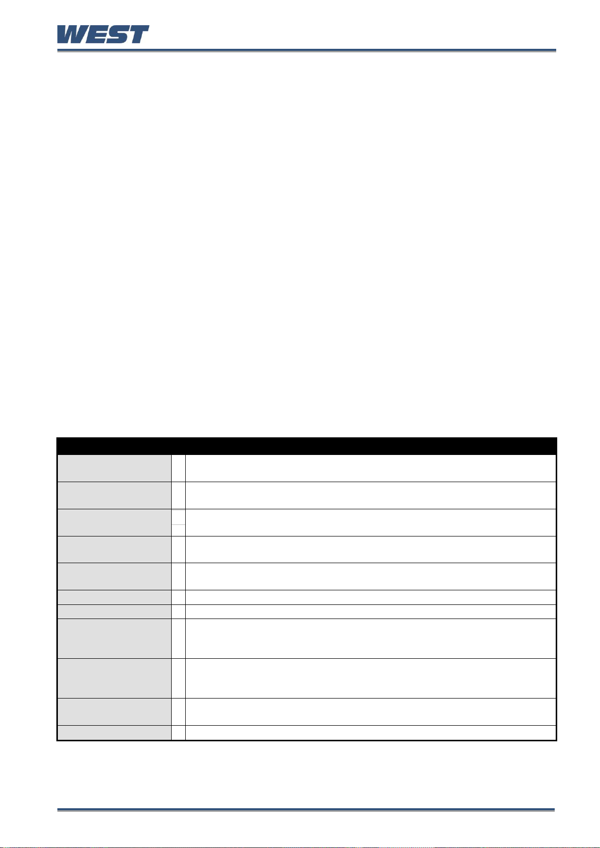
Pro-EC44 2-Loop Graphical Profile Controller & Recorder
SERVICE & PRODUCT INFORMATION SCREENS:
Plug-in Module
Information
Lists the type plug-in modules types in Slots 1, 2, 3 or A – see page 4 for a
full list of field upgradeable plug-in options.
Base Options
Lists factory fitted base options, from: 2nd Universal/Aux input; Output 4 &
5 Relay; Output 6 & 7 Linear mA/V DC.
Optional Features
Lists which other optional features are fitted/enabled, from: Profiler; USB
Port; Data Recorder and 8 Digital Inputs.
Firmware
Information
The type and version of firmware installed in the instrument.
Product Revision
Level
Software and Hardware update status.
Serial Number
The instrument serial number.
Date of Manufacture
The instrument Date of Manufacture (date format is dd/mm/yyyy).
Input 1 Calibration
Status
The base calibration status for each signal type on input 1.
Caution: Re-calibrate input 1 for mVDC, VDC, mADC, RTD or
Thermocouple CJC if they do not say “Calibrated” – see page 72
Input 2 Calibration
Status
The base calibration status for each signal type on optional input 2.
Caution: Re-calibrate input 2 for mVDC, VDC, mADC, RTD or
Thermocouple CJC if they do not say “Calibrated” – see page 72
Calibration Check
Due Date
The date re-calibration is due. – only shown if the Calibration Reminder is
enabled in the Input Configuration menu.
For Service Contact
Contact information for service, sales or technical support.
Service & Product Information Mode
This is read only information about the instrument, its modules and enabled features. It has
contact information to tell the user where they can obtain service, sales or technical support
for the product. Normally this is the manufacturer or suppliers’ details. Using the PC software,
the user can enter their own contact information. There are 7 lines of text - each up to 25
characters in length.
Entry into Service & Product Information Mode
The Service & Product Information Mode is entered from the Main Menu
Hold down R and press U to enter the Main Menu.
Press D or U to select the Service & Product Information Mode
Press R to enter the Service & Product Information Mode.
Navigating Product Information Mode
Press R to move forward or L to move backwards through the displayed
information.
Hold down R and press U to return to the Main Menu
Scrolling “Help Text” is shown at the bottom of the screens to aid navigation.
Pro-EC44 Product Manual - 59540-1 October 2013 Page 67
Page 75
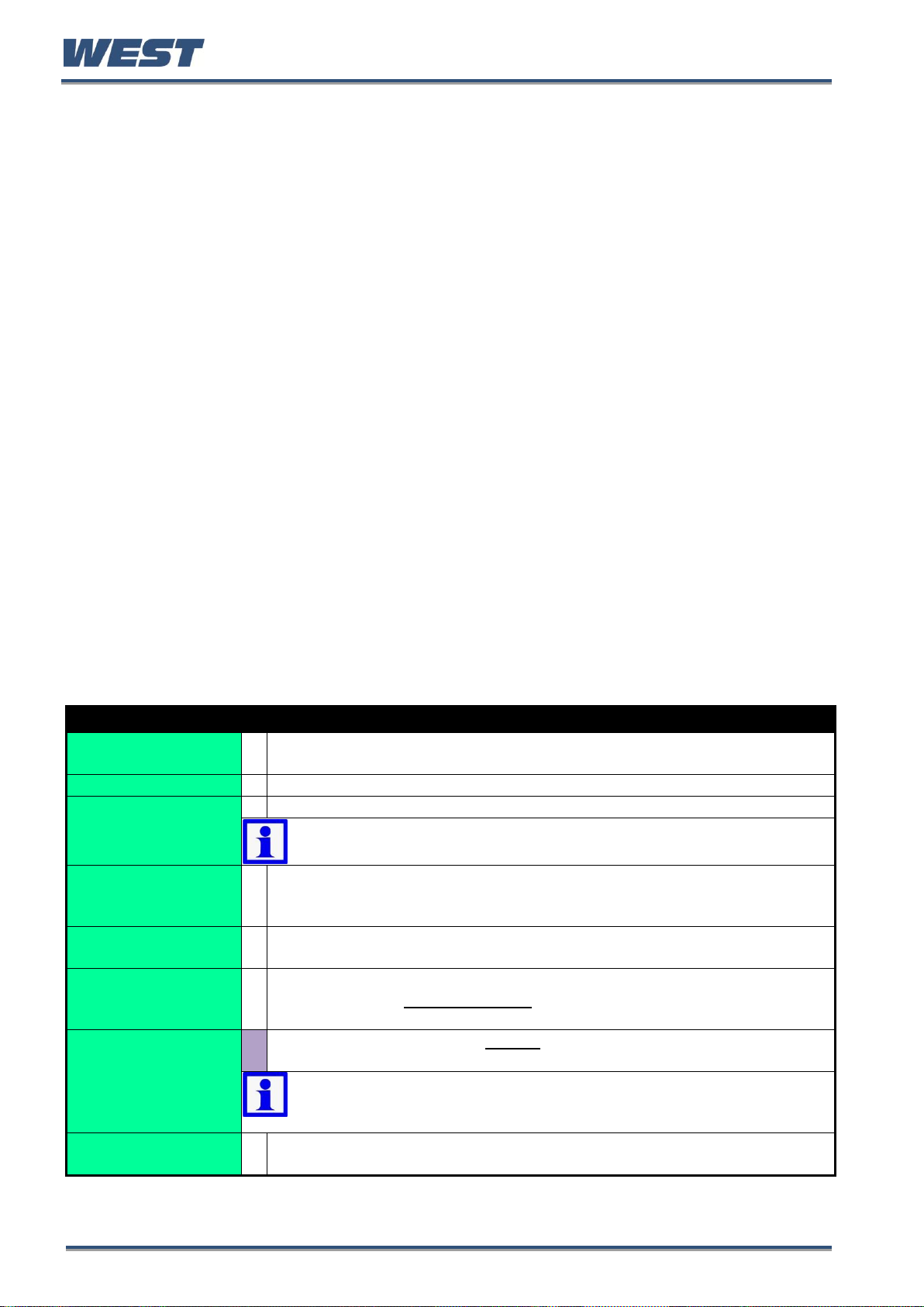
Pro-EC44 2-Loop Graphical Profile Controller & Recorder
AUTOMATIC TUNING MENU SCREENS
Automatic Tuning
Mode Unlocking
Enter correct code number to access the Automatic Tuning Menu.
Factory Default value is 10.
Control loop 1 or 2
Select which control loop you want to tune –if unit has 2 control loops.
Cascade Mode
To pre-tune a cascade slave, select open-cascade.
Note: When slave tuning is completed, repeat choosing open-cascade
to tune the master.
Pre-Tune Method
From: Pre-Tune Standard or Pre-Tune at Value. Standard Pre-Tune tests
the process response half-way from the activation point to the setpoint.
Pre-Tune at Valve allows the user to specify where the test occurs.
Pre-Tune Value
Sets the value at which the process is tested for Pre-Tune at Valve.
Caution: Consider possible over-shoot!
Pre-Tune Save
Location
Store the pre-tune result to one of 5 PID sets. The new PID terms can be
stored to any set, without changing the “active set” from control
configuration.
Run Pre-Tune on Set
n Now?
w
Turns pre-tune on/off for the chosen PID Set. If configured, the TUNE LED
indicator flashes whilst pre-tune is operating - *see below.
Note: Pre-tune is disabled in on-off control mode; if the PV is less than
5% of span from setpoint; during Profiles; if the setpoint is ramping or if
the selected control loop has been disabled.
Pre-Tune Status
Shows the current pre-tune status: Running or Stopped. If an attempt to
run pre-tune failed, the reason is shown.
Automatic Tuning Menu
The automatic tune menu is used to engage pre-tune and/or self-tune to assist setting up
proportional bands and the integral and derivative time values used by the control loops.
Pre-tune can be used to set PID parameters approximately. Self-tune may then be used to
optimise the tuning if required. See the Tuning section on page 99 for more information.
Pre-tune can be set to run automatically after every power-up by enabling Auto Pre-Tune.
Entry into the Automatic Tuning Menu
The Automatic Tuning Menu is entered from the Main Menu
Hold down R and press U to enter the Main Menu.
Press D or U to select the Automatic Tuning Menu.
Press R to enter the Automatic Tuning Menu.
Navigating the Automatic Tuning Menu
Press R to move forward or L to move backwards through the selections.
Press D or U to change values or engage and disengage the tuning as required.
Hold down R and press U to return to the Main Menu
Scrolling “Help Text” is shown at the bottom of the screens to aid navigation.
Pro-EC44 Product Manual - 59540-1 October 2013 Page 68
Page 76

Pro-EC44 2-Loop Graphical Profile Controller & Recorder
Engage Self-Tune
Turns self-tune on/off for the active PID Set. If configured, the TUNE LED
indicator is continuously on whilst self-tune is operating - *see below.
Note: Self-Tune disabled if control is On-Off or disabled. If engaged
during setpoint ramping, profile ramps or pre-tuning it is suspended until
the ramp or pre-tune is completed.
Self-Tune Status
Shows current self-tune status: Running or Stopped. If an attempt to run
self-tune failed, the reason is shown.
Auto Pre-Tune At
Power Up
Enables/disables automatic pre-tune. When enabled, this attempts to tune
the active PID set at every power-up (see Run Pre-Tune Now above).
Note: Auto Pre-tune applies standard pre-tune engagement rules at
power-up. It is disabled in on-off control mode; if the PV is less than 5%
of span from setpoint; during Profiles; if the setpoint is ramping or if the
selected control loop has been disabled.
Note: Pre-tune will flash the LED instead of turning it on, but flashing will be
obscured if the LED had been configured to be used in conjunction with other
functions and one of these is on.
* TUNE indication is the default function of LED 3 but the user may have altered the LED
functions or the labels using the PC Configuration Software. If LED 3 is used as a TUNE
indicator, it flashes while pre-tune is operating, and is continuously on whilst self-tune is
operating. If both pre-tune and self-tune are engaged the TUNE indicator will flash until pretune is finished, and is then continuously on.
Lost Lock Codes
All menu lock codes can be viewed or changed from configuration mode – see page 60. In
the event that the configuration mode lock code is forgotten, the instrument can be forced
into Lock Code Configuration from power-up, where the codes can be checked or set to new
values.
Forcing Lock Code Configuration
Power down the instrument.
Re-apply the power and hold down R and U for more than 5 seconds as the start-
up splash screen appears. The Lock Code Configuration menu is displayed.
Press R to move forward or L to move backwards through the screen elements.
Make note of the codes or press D or U to change their values if required.
Hold down R and press U to return to the Main Menu
Scrolling “Help Text” is shown at the bottom of the screens to aid navigation.
Pro-EC44 Product Manual - 59540-1 October 2013 Page 69
Page 77
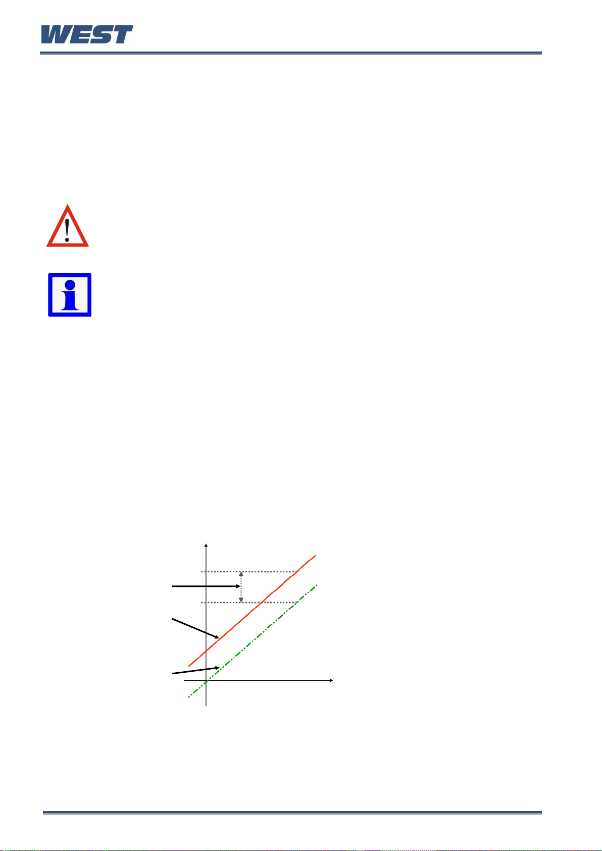
Pro-EC44 2-Loop Graphical Profile Controller & Recorder
CAUTION: Incorrect use of Calibration & Scaling can make the displayed
value very different from the actual process variable. There is no front
panel indication of when these parameters are in use.
Note: These methods do not alter the internal instrument calibration. Simply
choose Base Calibration to restore normal measured values.
Re-calibration of the internal base values is possible, but should only be
attempted by qualified personnel as it overwrites the factory calibration – see
Base Calibration Adjustment below if you think this may be required.
This example shows a positive offset
value. For example:
If the process displays 27.8 when it
should read 30, The error is -2.2 so
an applied offset of +2.2 would
change the displayed value to 30.
The same offset is applied to all
values, so at 100.0 the new displayed
value would be 102.2.
Single Point ‘Offset
Calibration’ value
New Displayed Value
Original Displayed Value
9 Input Calibration & Multi-point Scaling
User Calibration
The process inputs can be adjusted to remove sensor errors or to match the characteristics
of the attached process. For each loop, independent use of base (unadjusted), single point
offset or two point calibration strategies are possible, as is the use of multi-point scaling for
the displayed values of linear inputs. These parameters are in the Input 1 & 2 calibration submenus of Input Configuration Sub-Menu Screens - page 46.
Calibration Reminder
If the Data Recorder feature is fitted, a calibration reminder can be set for a future date.
From this date a daily reminder is shown (and shown at every start-up), until a new date has
been set. This is useful in applications that require a regular check of the measured accuracy
– see Input Configuration Sub-Menu Screens on page 46.
Single Point Calibration
This is a ‘zero offset’ applied to the process variable across the entire span. Positive values
are added to the reading, negative values are subtracted. It can be used if the error is
constant across the range, or the user is only interested in a single critical value.
To use, select Single Point Calibration from the input calibration menu, and simply enter a
value equal, but opposite to the observed error to correct the reading.
Pro-EC44 Product Manual - 59540-1 October 2013 Page 70
Figure 44. Single Point Calibration
Page 78

Pro-EC44 2-Loop Graphical Profile Controller & Recorder
This example shows a positive Low
Offset and a negative High Offset. For
example:
If the process displays a low end error
of +0.5 at zero, an offset of -0.5 would
change the value to 0.0
A high end value of 98.3 with a +1.7
offset would read 100.0.
There is a linear relationship between
these two calibration points.
CAUTION: Choose values as near as possible to the bottom and top of
your usable span to achieve maximum calibration accuracy. The effect of
any error can grow at values beyond the chosen calibration points.
Original Displayed Value
New Displayed Value
Calibration High Offset
Calibration Low Offset
Calibration High
Process Value
Calibration Low
Process Value
Two Point Calibration
This method is used where an error is not constant across the range.
Separate offsets are applied at two points in the range to eliminate both “zero” and “span”
errors. To use:
1. Measure and record the error at a low point in the process.
2. Measure and record the error at a high point in the process.
3. Go to the first two point input calibration screen.
a. Enter the desired low point value as the Calibration Low PV value.
b. Enter an equal, but opposite value to the observed error as the Calibration Low
Offset to correct the error at the low point.
4. Go to the second two point input calibration screen.
a. Enter the desired high point as the Calibration High PV value.
b. Enter an equal, but opposite value to the observed error as the Calibration High
Offset to correct the error at the high point.
Figure 45. Two Point Calibration
Pro-EC44 Product Manual - 59540-1 October 2013 Page 71
Page 79

Pro-EC44 2-Loop Graphical Profile Controller & Recorder
Set the scale limits, and then enter
the 1st scaling point (this is a % of the
scaled input span, and the desired
display value to be shown at that input
value. Next set the 2nd point and
display value, followed by the 3rd etc.
Continue unit all breakpoints are used
or you have reached 100% of the
input span.
A breakpoint set at 100% ends the
sequence
CAUTION: Any calibration adjustment must only be performed by
personnel who are technically competent and authorised to do so.
The equipment used must be in a known good state of calibration.
New Linearized
Displayed Values
Non-linear signal
Scale Lower Limit
Scaling Points 2, 3 & 4
To Scale Upper Limit
Scaling Point 1
Multi-point Scaling
If an input is connected to a linear input signal (mA, mV or VDC), multi-point scaling can be
enabled. This allows the linearization of a non-linear signal. – see Input Configuration Sub-
Menu Screens on page 46.
The Scale Input Upper & Lower Limits define the values shown when the input is at its
minimum and maximum values. Up to 15 breakpoints can scale the input vs. displayed value
between these limits. It is advisable to concentrate the break points in the area of the range
with the most non-linearity, or an area of particular importance to the application.
Figure 46. Multi-point Scaling
Base Calibration Adjustment
Calibration of each input type is carried out during manufacture. This can be verified in the
Service and Product Info screens.
Re-calibration of the internal base values is possible, but should only be attempted by
qualified personnel as it overwrites the factory calibration.
For most applications, base re-calibration is not required during the lifetime of the instrument.
WARNING:
BASE CALIBRATION SHOULD ONLY BE PERFORMED IF ERRORS HAVE BEEN
ENCOUNTERED. REFER TO CALIBRATION CHECK BELOW.
Required Equipment
To verify the accuracy of the instrument or to carry out recalibration, a suitable calibration
signal source is required for each input type as listed below. Accuracy must be better than
±0.05% of reading:
1. DC linear inputs: 0 to 50mV, 0 to 10VDC and 0 to 20mADC.
2. Thermocouple inputs - complete with 0ºC reference facility, appropriate thermocouple
functions and compensating lead wire.
3. RTD inputs: decade resistance box with connections for three-wire input.
Pro-EC44 Product Manual - 59540-1 October 2013 Page 72
Page 80

Pro-EC44 2-Loop Graphical Profile Controller & Recorder
Note: The 50mV calibration phase MUST always be calibrated before calibration
of the thermocouple input.
INPUT CALIBRATION PHASES
Type
Signal
(<0.05% error)
Cable Type
Input 1 Terminals
Input 2 Terminals
+ - +
-
DC milli-volt
50 mV
Copper Wire
2 3 6
7
DC voltage
10 V
Copper Wire
2 3 6
7
DC milliamps
20 mA
Copper Wire
3 1 7
5
RTD
200 ohm
Copper 3-Wires
1
2 & 3
5
6 & 7
Thermocouple
0ºC K type source
K Thermocouple Wire
2 3 6
7
Performing a Calibration Check
1. Setup input 1 for the input signal type to be checked.
2. Power up the instrument and correctly connect the signal source.
Leave powered up for at least five minutes for RTD and DC linear inputs, and at least
30 minutes for thermocouple inputs.
3. After the appropriate delay for stabilisation, check the calibration at a number of
cardinal points by applying the appropriate input signal.
The observed readings should be within the tolerances stated in the specifications
(see page 245).
4. Test the other signal types as above if required.
5. Repeat the process for input 2 if fitted.
Recalibration Procedure
For each process input, recalibration is carried out in five phases as shown in the table
below; each phase corresponds to a basic input type.
1. For optimum accuracy, leave the instrument power-up for >30 minutes to warm up before
beginning the calibration, and then toggle the power off/on to restart the instrument.
2. During the power-up “splash screen”, press D and R together until the Input 1
Calibration Status screen is displayed.
3. Correctly connect the 1st phase signal (50mV), then press R to select the first phase
4. Press D + U to initiate the calibration.
5. During calibration the message “50mV DC Input Calibrating” will display for a few
seconds. This should be followed by the “Calibration Successful” confirmation.
Pro-EC44 Product Manual - 59540-1 October 2013 Page 73
Page 81

Pro-EC44 2-Loop Graphical Profile Controller & Recorder
Note: The Calibration Mode automatically exits if there is no button activity for
two minutes.
6. If the input is misconnected or an incorrect signal is applied, the calibration will be aborted
and the values will not be altered. The display will show “Failed: Signal Too Small!” or
“Failed: Signal Too Large!”. Correct the problem and repeat that phase before continuing.
7. Press R to select the next calibration phase.
8. Repeat this process for each input type until all the phases are calibrated. For each phase,
ensure that the correct input is applied, using the appropriate connections.
9. If the instrument has 2 process inputs, when the first input sequence completes, the Input
2 Calibration Status screen is displayed. Repeat the procedure from 3 above for this input.
10. Once calibration is complete, recorder versions will ask for a Calibration Reminder Date.
If required, this can be changed to the date of your next calibration check. Ensure that
Calibration Reminders are enabled in Input Configuration to receive a reminder.
11. Press R + U to exit to the main menu.
Pro-EC44 Product Manual - 59540-1 October 2013 Page 74
Page 82

Pro-EC44 2-Loop Graphical Profile Controller & Recorder
CAUTION: The response time is ≥0.25 seconds. Signals applied for less
than this time may not register and the function might not change state.
A diagnostic screen assists commissioning and fault
finding by showing the current signal state for all
digital inputs.
Slot A, C1 to C8 & Soft digital input status ( =
Active, Ø = Unavailable)
Profile select bit format (BCD or Binary)
Profile selected (example shown: C1-C3 = 011 = 6)
Digital inputs can be inverted to reverse their
action making an “on” input behave as off.
Step thorough each input using the R key.
Press U to invert the highlighted input and D
to un-invert . Hold R down to skip to next
screen accepting the values shown.
Highlighted Input
10 Digital Inputs
Digital inputs are driven to one of two states (active or inactive) by an applied voltage signal
or a contact opening/closing.
A total of 9 physical digital inputs are possible on this instrument. A multiple digital input can
be installed at time of purchase, and a single plug-in module can be fitted in option slot A.
Digital Signal Type
The digital inputs can be connected to volt-free contacts, or to a voltage signal (compatible
with TTL). They can often be used in parallel with equivalent menu selections, where either
can change function status.
Some inputs are level sensitive, while others are edge sensitive requiring a High to Low or
Low to High transition to change functions status. Pre-Tune is always off at power-up (except
if auto pre-tune is enabled), but other edge sensitive functions retain their power off status at
power on. See the tables below for details.
Open contacts (>5000Ώ) or 2 to 24VDC signal = Logic High (logic low if inverted).
Closed contacts (<50 Ώ) or -0.6 to +0.8VDC signal = Logic Low (logic high if inverted).
Inverting Digital Inputs
Pro-EC44 Product Manual - 59540-1 October 2013 Page 75
Page 83

Pro-EC44 2-Loop Graphical Profile Controller & Recorder
The four soft digital inputs can be
configured by combining physical inputs,
alarms & events using Boolean logic.
Input AND selections are then globally
OR’d with the input OR selections, the
alarms & the events. By using the invert
inputs function, NAND & NOR
equivalents can be created.
Some or all of inputs C1 to C7 can be used for
profile selection. If used in this way they cannot
be used for any other functions.
Soft inputs and any physical digital inputs not
allocated for profile selection can be used to
change the instrument status.
Each input can only perform a single function.
The possible functions are listed below.
Function
Logic High*
Logic Low*
Sensitivity / Functions’
Power On State
Loop 1 Control Select
Enabled
Disabled
┌ ┐
/ Retained
Loop 2 Control Select
Enabled
Disabled
┌ ┐
/ Retained
Loop 1 Auto/Manual Select
Automatic
Manual
┌ ┐
/ Retained
Loop 2 Auto/Manual Select
Automatic
Manual
┌ ┐
/ Retained
Loop 1 Setpoint Select
Main SP
Alternate SP
┌ ┐
/ Retained
Loop 2 Setpoint Select
Main SP
Alternate SP
┌ ┐
/ Retained
Loop 1 Pre-Tune Select
Stop
Run
┌ ┐
/ OFF
Loop 2 Pre-Tune Select
Stop
Run
┌ ┐
/ OFF
Loop 1 Self-Tune Select
Stop
Run
┌ ┐
/ Retained
Soft Digital Inputs
In addition to the physical digital inputs, four “soft” digital inputs are available. They are used
to select functions in the same way as the physical inputs.
Digital Input Functions
Single Functions
Digital inputs can often work in parallel with equivalent menus, where either can change
function status.
In the table below, █ = Level Sensitive: Where a High or low signal sets the function status.
┌ ┐
= Edge Sensitive: High-Low or Low-High transition changes the function status.
Pre-Tune is always off at power on (except if auto pre-tune is in use), and profile recovery is
as configured, but others functions retain their power off status when the power returns.
Pro-EC44 Product Manual - 59540-1 October 2013 Page 76
Page 84

Pro-EC44 2-Loop Graphical Profile Controller & Recorder
Loop 2 Self-Tune Select
Stop
Run
┌ ┐
/ Retained
Profile Run/Hold
Hold
Run
┌ ┐
/ As configured
Profile Hold Segment Release
No Action
Release
┌ ┐
/ Retained
Profile Abort
No Action
Abort
█ / As Digital Input
Data Recorder Trigger
Not Active
Active
█ / As Digital Input
Output n Forcing
Off/Open
On/Closed
█ / As Digital Input
Clear All Latched Outputs
No Action
Reset
█ / As Digital Input
Output n Clear Latch
No Action
Reset
█ / As Digital Input
Key n Mimic (for L D U R)
No Action
Key Pressed
█ / As Digital Input
C1
C1 to C2
C1 to C3
C1 to C4
C1 to C5
C1 to C6
C1 to C7
Binary
0 to 1
0 to 3
0 to 7
0 to 15
0 to 31
0 to 63
BCD
0 to 1
0 to 3
0 to 7
0 to 9
0 to 19
0 to 39
0 to 63
Using Binary To Select Profile Numbers
Selection of profiles is via a simple binary bit pattern. C1 is the least significant bit (LSB).
C6 to C1
C5 to C1
C4 to C1
C3 to C1
C2 to C1
C1
000000 to 111111
00000 to 11111
0000 to 1111
000 to 111
00 to 11
0 to 1
(0 to 63)
(0 to 31)
(0 to 15)
(0 to 7)
(0 to 3)
(0 to 1)
Using BCD To Select Profile Numbers
A single BCD switch can be used to select profiles 0 to 9 using C1 to C4, with a bit pattern identical to
standard binary. For larger numbers, a double BCD switch arrangement is needed. A separate binary
pattern is applied to C5 to C7 for the “tens” digit (10 = 001, 20 = 010, 30 = 011 etc).
Any number combination higher than 63 is invalid.
Multiples of ten (0x to 6x)
Multiples of one (x0 to x9)
C7 to C1
C6 to C1
C5 to C1
C4 to C1
C3 to C1
C2 to C1
C1
000 to 110
00 to 11
0 to 1
0000 to 1001
000 to 111
00 to 11
0 to 1
(0x to 6x)
(0x to 3x)
(0x to 1x)
(x0 to x9)
(x0 to x7)
(x0 to x3)
(x0 to x1)
Profile Selection via digital inputs
For instruments with the profiler option, the multi-digital input option can be used to select the
profile to run using either a standard binary bit pattern, or binary coded decimal from BCD
switches. Profile selection inputs are all level sensitive ( █ ), with a high/open signal equating
to a binary 1 (assuming non-inverted), and a low/closed signal equating to a binary 0
(assuming non-inverted).
Profiles are numbered 0 to 63. Select inputs C1 to Cn for the required number of profiles,
from the table:
Pro-EC44 Product Manual - 59540-1 October 2013 Page 77
Page 85

Pro-EC44 2-Loop Graphical Profile Controller & Recorder
Note: Cascade control is only available on models fitted with the 2nd control
loop. The master loop uses input 1; and the slave loop uses input 2.
PRODUCT
0-300°C
Slave SP
0-100%
Output
SLAVE SENSOR
MASTER SENSOR
250°C Master Setpoint
HEATER
OIL JACKET
MASTER
IP1
OP
SP
SLAVE
IP2
OP
SP
11 Cascade Control
Applications with long time lags (e.g. with two or more capacities such as heated jackets) can
be difficult to control with a single control loop. The solution is to split the process into two or
more cascaded loops consisting of a Master and Slave(s) acting on a common actuator.
Ideally, the slave loop’s natural response time should be at least 5 times faster than the
master.
The master controller measures the process temperature and compares it to the desired
product setpoint. Its correcting variable (0 to 100% PID output) becomes the slave’s effective
setpoint (scaled to suit the process). This setpoint is compared to the slave’s process input,
and the controlling actuator is adjusted accordingly.
Example Cascade Application
In this example the controlling actuator is a heater, indirectly heating the product via an oil
jacket. The maximum input to the slave represents 300ºC, thus restricting the jacket
temperature. At start-up the master compares the product temperature (ambient) to its
setpoint (250ºC) and gives 100%. This sets the maximum slave setpoint (300ºC), which is
compared to the oil temperature (ambient) and the slave requests maximum heater output.
Figure 47. Cascade example
As the oil temperature rises towards the slave setpoint, its output falls. Gradually, the product
temperature will also begin rising, at a rate dependant on the transfer rate/lag between the oil
jacket and the product. Eventually this causes the master’s PID output to decrease, reducing
Pro-EC44 Product Manual - 59540-1 October 2013 Page 78
Page 86

Pro-EC44 2-Loop Graphical Profile Controller & Recorder
CAUTION: The master process value is not under control when the
cascade is open, but will be affected by the slave process. The operator is
responsible for maintaining safe conditions.
CAUTION: Manual mode disables the cascade loop. It also ignores any
output power limits, valve open/close limits and the control enable/disable
setting. The operator is responsible for maintaining the process within safe
limits.
Note: The cascade remains open until you pre-tune the master or manually
select Cascade-Closed.
the slave setpoint. The oil temperature is reduced towards the new slave setpoint. This
continues until the system becomes balanced. The result is quicker, smoother control with
the ability to cope with changes in the load. Overshoot is minimised and the jacket
temperature is kept within acceptable tolerances.
Normal Cascade Operation
During operation, the master and slave are coupled together and. "Cascade" is displayed.
The master process value and setpoint are most relevant to the user. The master setpoint is
directly adjustable. The process value of the slave controller is displayed for information only.
Cascade-Open
The cascade can be disconnected (via digital inputs or menu selection), switching from
normal operation to direct control of the slave. "Cascade-Open" is displayed. Opening the
cascade is “Bumpless”. The current cascade value is used as the initial slave setpoint
(displayed as “SlaveSP”). The process is then controlled and adjusted solely by the slave
controller using this setpoint. Switching back to Cascade is also bumpless.
Manual Mode
The controller can be put into manual mode (via digital inputs or menu selection), switching
from normal operation to direct control of the slave loop’s correcting variable. Manual power
is adjusted from 0% or -100 to 100%. "MAN" is displayed.
Cascade Tuning
The user can tune the slave and master loops manually, or use the pre-tune feature (see
Controller Tuning on page 99).
In either case the slave control loop must first be optimised on its own, followed by the
master loop in combination with the previously tuned slave.
To automatically pre-tune a cascade:
1. Go to the Automatic Tuning menu
2. Select “Cascade-Open” from the pre-tune menu to tune the PID set(s) on the slave.
3. After the slave has successfully tuned, pre-tune the master/slave combination by
selecting “Cascade-Closed” from the pre-tune menu.
Pro-EC44 Product Manual - 59540-1 October 2013 Page 79
Page 87

Pro-EC44 2-Loop Graphical Profile Controller & Recorder
To manually tune a cascade:
1. Select Cascade-Open from the Cascade Control menu, breaking the link between the
master and slave loops.
2. Set the slave controller setpoint manually to the appropriate value for your application.
3. Tune the slave for relatively fast control (‘proportional only’ is often sufficient).
4. Select Cascade-Closed from the Cascade Control menu to link the master and slave
loops, then tune the master/slave combination.
Pro-EC44 Product Manual - 59540-1 October 2013 Page 80
Page 88

Pro-EC44 2-Loop Graphical Profile Controller & Recorder
Note: Ratio control is available on models with the 2nd Auxiliary Input, or two loop
models. The feature and information displayed is optimised for control of burner
fuel/air, but can be used in other flow ratio applications.
Atomization Air
NO
Burner
Air
Fuel
Air Valve
12 Ratio Control
A ratio control loop is used where the quantity of one of the material is to be controlled in
proportion to the measured quantity of a second material. The controller mixes the materials
at the desired ratio by adjusting the flow of input 1. The flow of input 2 may be controlled
separately, but is not controlled by the ratio control loop itself.
The process value used by the controller is therefore determined by the ratio of the two
inputs rather than a single measured variable.
Stoichiometric Combustion
Below is an example of stoichiometric combustion ratio control. For optimum combustion the
fuel-air ratio is set so that there are no flammable residues in the waste gas.
Figure 48. Ratio Control Example
It is normal in this application to display the process value and setpoint as relative values
rather than the physical ratio or absolute values. A scaling factor is set such that the
displayed value will be 1.00 at the correct stoichiometric ratio for the application.
Inputs 1 and 2 are configured and scaled to match the attached flow meters.
In this example a 4 to 20mA signal at x1 represents 0 to 1000m3/h of airflow controlled by a
valve. The second 4 to 20mA signal at x2 represents 0 to 100m3/h of fuel oil. The fuel flow is
not affected by this control loop.
Atomizing air is fed in with the fuel oil at a constant rate ‘NO’. This must be considered when
calculating the correct fuel/air mix. Total airflow is x1 + NO.
The stoichiometric factor, SFac is entered to match the desired ratio. E.g for 10 parts total
airflow to one part fuel, SFac would be 10.
The setpoint (entered as a relative value such as 1.00) is multiplied by SFac when
calculating the control deviation. E.g. with a setpoint of 1.00 and SFac of 10 the controller
Pro-EC44 Product Manual - 59540-1 October 2013 Page 81
Page 89

Pro-EC44 2-Loop Graphical Profile Controller & Recorder
attempts to make the physical ratio 10. With a setpoint of 1.03 it would attempt to make the
ratio 10.3 for 3% excess air.
The instantaneous (controlled) process value is calculated from the physical ratio, divided by
SFac. Like the setpoint, this is displayed as relative value.
E.g. if SFac is 10, with 59.5m3/h airflow measured at x1, 0.5m3/h atomising air applied at NO
and 6m3/h fuel is measured at x2, the instantaneous process value would be:
If fuel flow remained at 6m3/h and the setpoint was adjusted to 1.05 (5% excess air), the
controller would increase the x1 air flow to 62.5m3/h.
Typical Ration display with Setpoint at 1.05
Pro-EC44 Product Manual - 59540-1 October 2013 Page 82
Page 90

Pro-EC44 2-Loop Graphical Profile Controller & Recorder
Note: The user may not even be aware of a sensor fault, so it is strongly
recommended that signal break alarms are configured for both inputs to provide
a notification if problems occur.
Note: If both signals are lost at the same time, the PV value display is replaced
with “OPEN” and the normal sensor break actions occur.
13 Redundant Input
If the 2nd universal input is fitted, the second input can be configured as a redundant input for
the main process input. This increases process security by protecting against the possible
loss of valuable product resulting from sensor failure.
A second sensor is connected to input 2 so that if the main sensor fails, the instrument
automatically switches to this backup or “redundant” sensor.
In this condition, if input 1 has a signal break alarm configured it will activate, but any other
process input or control status alarms seamlessly switch to the 2nd input. The 2nd input
continues to be used until the signal to input 1 is restored.
The redundant sensor must be of the same type, and be correctly located in the application
ready to take over if needed. If the redundant input option is selected, the 2nd input cannot be
used for other functions.
Pro-EC44 Product Manual - 59540-1 October 2013 Page 83
Page 91

Pro-EC44 2-Loop Graphical Profile Controller & Recorder
Note: Some modulating valves have positioning circuitry to adjust the valve
position. These require a DC linear mA or voltage output and use the standard
control algorithm (Set Control Mode to Standard).
CAUTION: The windings of a valve motor effectively form an
autotransformer. This causes a voltage doubling effect when power is
applied to either the Open or Close terminal, causing twice the supplied
voltage at the other terminal.
“Open” Relay
“Close” Relay
120V Supply
Open Valve Winding
Close Valve
Valve Common
14 Valve Motor Drive / 3-Point Stepping Control
When directly controlling the motor of a modulating valve or damper, set the Control Mode to
VMD in configuration mode to enable the 3-point stepping Valve Motor Drive control
algorithm.
The term “3-point stepping” is used because there are 3 output states, open valve, close
valve or stopped (no action). Switched outputs move the valve further open, or further closed
when a control deviation error is detected. If the error is reduced to zero, no further output is
required until the load conditions change.
VMD mode doesn’t allow on-off control (the minimum proportional band equates to 0.5% of
the scaled input span) and usually requires PI control, where the derivative parameter is set
to OFF.
Special Wiring Considerations for Valve Motor Control
Valve motor drive mode must have two identical outputs assigned to position the valve. One
to open and one to close the valve. These outputs can be two single relays, two triacs, two
SSR drivers or one dual relay, but it is recommended to use two single relays (SPDT
change-over contacts), and to interlock the wiring as shown. This prevents both motor
windings from being driven at the same time, even under fault conditions.
Switching actuators directly connected to the valve motor must only be used up to half of
their rated voltage. The internal relay and triac outputs in this instrument are rated at 240VAC
Therefore, the maximum motor voltage when using them is therefore 120V unless
interposing relays are used. Interposing relays or other devices used to control the valve
must themselves be rated for twice the motor supply voltage.
Pro-EC44 Product Manual - 59540-1 October 2013 Page 84
Page 92

Pro-EC44 2-Loop Graphical Profile Controller & Recorder
CAUTION: These limits must be used with care. They are effectively control
power limits. Do not set values that prevent proper control of the process!
Position Feedback
In VMD mode this instrument uses a boundless (open-loop) 3-point stepping algorithm. It
does not require any kind of position feedback in order to correctly control the process and
can therefore avoids problems associated with faulty feedback signals.
However, where valve feedback is available it can still be displayed in a bar-graph as a
percentage open (0 to 100%). Position feedback is usually provided by means of a
potentiometer mechanically linked to the valve. The output of a related flow meter can also
be used to indicate the relative valve position. Flow meters typically have linear 0-20/4-20mA
or 0-5/0-10V signals. To display the position/flow signal the 2nd input is must be configured
for this purpose.
The input is adjusted and scaled to show 0 to 100% representing valve fully closed to fully
open, or a flow rate equating to fully closed to fully open. The valve position scaling
parameters are set in the Input Configuration sub menus – see page 46.
Valve Limiting
When valve position/flow indication is in use, the signal can be used by the controller to limit
the valve movement. Upper and/or lower limits can be set beyond which it will not attempt to
drive the valve. The valve open and close limits are set in the Control Configuration sub
menu – see page 50.
Pro-EC44 Product Manual - 59540-1 October 2013 Page 85
Page 93

Pro-EC44 2-Loop Graphical Profile Controller & Recorder
15 Setpoint Sources
The setpoint is the target value at which the instrument attempts to maintain the process
variable. Each loop can have a Main “local” setpoint set from the keypad and an Alternate
setpoint.
Loop 1 Setpoint Sources
Loop 1 can have a Main “local” setpoint set from the keypad and an Alternate setpoint.
The alternate setpoint source can be either another local Setpoint or a remote setpoint
(RSP), set by a mA or V DC signal applied to the 2nd input or to auxiliary input A. The control
loop can only use one setpoint source at a time for each loop. This is called the “Active
Setpoint”. If the profiler option is fitted this provides the setpoint when the profiler is in use,
replacing both main an alternate setpoints.
Main/alternate setpoint selection can be made via a digital input; from the Control
Configuration menu or if enabled in the Display Configuration sub-menu, an operator screen
can be used to select the setpoint. The chosen setpoint selection method can be used to
permanently select one of the setpoints, or allow switching between them.
Refer to the Control Configuration Sub-Menu Screens on page 50 for setpoint settings.
Loop 1 Profile Setpoint
When in profile control mode, the selected profile always provides the active setpoint source
for loop 1 (see page 87). Once profile control mode is exited, the selected main or alternate
setpoint for loop 1 becomes active again.
Loop 2 Setpoint Sources
Loop 2 can have a Main “local” setpoint set from the keypad and an Alternate setpoint.
The alternate setpoint source can be either another local Setpoint” or a remote setpoint
(RSP), set by a mA or V DC signal applied to auxiliary input A. The control loop can only use
one setpoint source at a time for each loop. This is called the “Active Setpoint”. If the profiler
option is fitted this provides the setpoint, replacing both main an alternate setpoints, when 2loop profiling is in use.
Main/alternate setpoint selection can be made via a digital input; from the Control
Configuration menu or if enabled in the Display Configuration sub-menu, an operator screen
can be used to select the setpoint. The chosen setpoint selection method can be used to
permanently select one of the setpoints, or allow switching between them.
Refer to the Control Configuration Sub-Menu Screens on page 50 for setpoint settings.
Loop 2 Profile Setpoint
If the selected profile was configured to control the setpoint of both loops, it will provide the
active setpoint source (see page 87). Once profile control mode is exited, the selected main
or alternate setpoint for loop 2 becomes active again.
Pro-EC44 Product Manual - 59540-1 October 2013 Page 86
Page 94

Pro-EC44 2-Loop Graphical Profile Controller & Recorder
Note: Even if profile editing is enabled, changes to the current and next segment
or a running profile will not take effect until the profile is next run. Changes to
other segments will take effect immediately.
Note: Profile Header information is only stored to memory as the Segment
creation sequence begins. No profile is created if you exit before this point.
Segment information is stored as each segment is created, but the profile
remains invalid until an end or join segment is defined.
16 Profiler
This section covers the Profiler (or setpoint programmer) option. To confirm if profiling is
enabled on your controller, refer to the Service & Product Info menu (see page 67).
Introduction
The Profiler feature allows the user to store up to 255 profile segments, shared between a
maximum of 64 Profiles. Each profile controls the value of the setpoint over time; increasing,
decreasing or holding their values as required. The profile can control both setpoints if the 2nd
control loop is fitted.
Profiler options and screens are added to the Main Menu and Operation Mode – See pages
63, 66 & 36.
Profiler Enabling
Controllers supplied without the Profiler option installed can be upgraded by purchasing a
licence code number. Refer to the Field Upgrade information on page 4.
To obtain the correct code you must tell your supplier the instrument serial number – this can
be found in the Service & Product Info menu (see page 67).
To enter the licence code, hold down the L + D keys during the power-up splash screen.
Enter the 16-character licence code in the displayed screen and press R.
Profile Components
General profile configuration settings apply to all profiles. They enable or disable “profile
editing while running”, and automatic starting of the selected profile if it has been configured
with a delay or day & time start trigger.
If delay or day & time start triggers are disabled, profiles can only be manually started, and
this is with immediate effect even if they have a delay or day & time trigger defined.
If delay or day & time start triggers are enabled, delayed starts are possible, and if the
selected profile has a day & time trigger it will wait until the time set and before starting.
Profile Header & Segment Information
Each profile has its own header information plus 1 or more segments. The header
information is unique for each profile, it contains the profile’s name; if it controls just one or
both loops; how it should start & stop; the abort & power-loss recovery actions; and how
many times it should be repeated.
Segments can be ramps, dwells, steps or special segments such as holds, ends, joins or
loop-backs.
Pro-EC44 Product Manual - 59540-1 October 2013 Page 87
Page 95
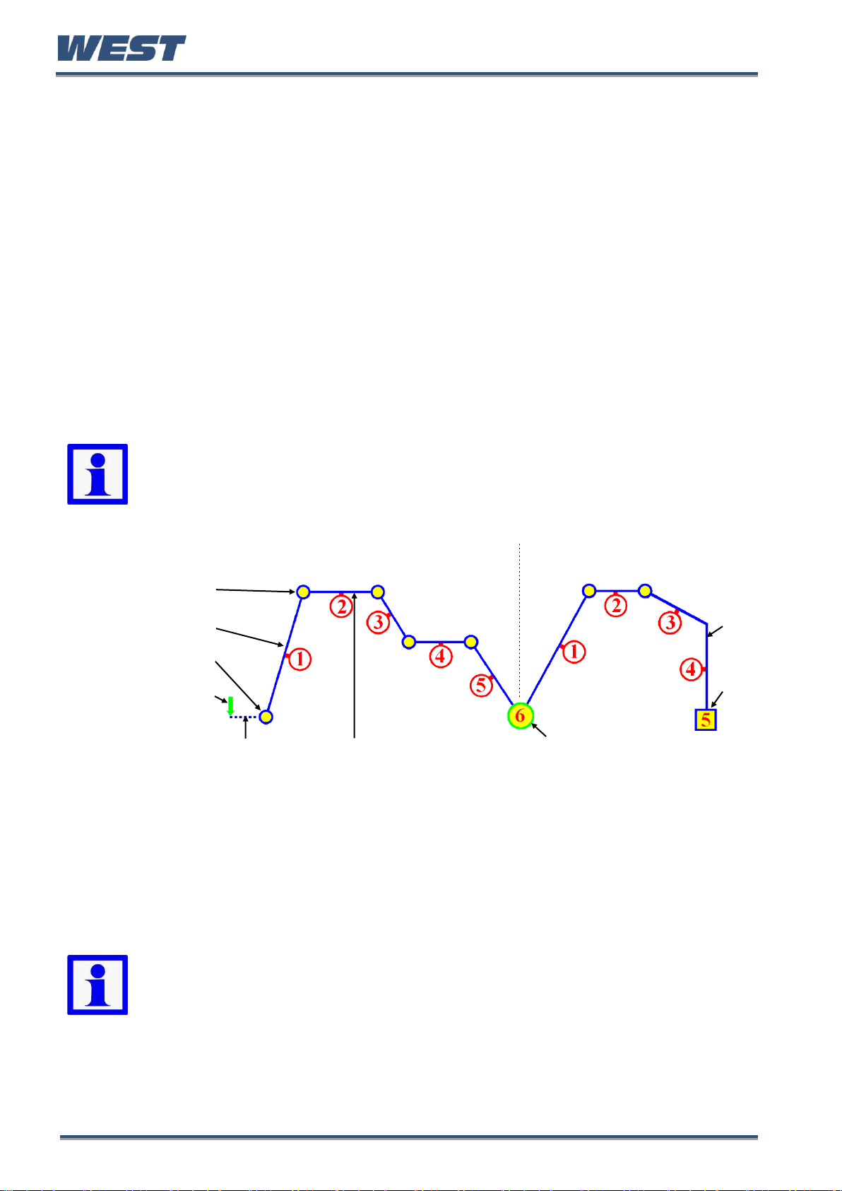
Pro-EC44 2-Loop Graphical Profile Controller & Recorder
Note: Profiles outside current setpoint limits will not run, A “profile not valid” error
shows if you attempt to run a profile under these circumstances.
PROFILE 1
PROFILE 9
Seg. 1 Target SP
Ramp (Time/Rate)
Starting Setpoint
Start
Trigger
Step
End
Timer or Delay Dwell
Join (Profile 1 to Profile 9)
Note: When using the instrument as a two loop profiler Ramp-Rate type
segments are not available. Calculate the time from the starting value to the
target setpoint and use Ramp-Time instead.
If the instrument also has the data recorder option, its real time clock (RTC) expands the
profiling capabilities by adding Day & Time profile start options, releasing of hold segments at
a specific time of day and changing the power fail recovery option to one based on the length
of time the power has been off. These features are explained below and in the Profiler Setup
and Profile Control menus (See pages 63 & 66).
Profile Starting & Standard Segments
The example profile below explains the standard segment types required to make a simple
profile or profile sequence. A Start Trigger is the instruction to begin the selected profile.
This can be from the profile control menu, a digital input signal, via a serial communications
command or if enabled in the display configuration, the profile can be controlled from an
operator screen.
Following a Start Trigger, profiles can start immediately, after a delay, or using the Day &
Time start timer (Day & Time start available on with the Recorder option only). Following the
start trigger, the remaining delay time or the start day & time are shown in the profile status
bar-graph until the profile begins running.
Figure 49. Profile Starting and Standard Segment Types
Ramps and Step Segments have target setpoint that they will reach as they finish.
If a segment is a Ramp-Time type, the slope needed to reach the target setpoint in the
defined time will change depending on the starting setpoint value.
For a Ramp-Rate segment, the slope is defined by the segments Ramp Rate, so the time to
reach the target setpoint will change instead. This is of particular significance for the first
segment, since the starting value of the process may not be known in advance.
A Dwell (often called a “soak”) holds the previous setpoint value for the specified dwell time.
Step segments jump straight to the new target setpoint value.
An End segment ends the profile or profile sequence.
If the last segment is a Join, the “join target” profile will begin running.
Pro-EC44 Product Manual - 59540-1 October 2013 Page 88
Page 96

Pro-EC44 2-Loop Graphical Profile Controller & Recorder
Note: If the join target has been deleted the profile sequence will abort and the
last profiles abort action will apply.
Note: When using the instrument as a two loop profiler Ramp-Rate type
segments are not available. Calculate the time from the starting value to the
target setpoint and use Ramp-Time instead.
2-LOOP PROFILE
Independent
Setpoints
Loop 1
Loop 2
Seg. Nos
Both loops on same time-base
Note: Auto-Hold settings are independent for each loop. Either loop can cause
the profile to auto-hold, holding both loops at the current setpoint value. The
profile continues only when both loops are back within their hold bands.
Two Loop Profiles
If the instrument is configured to control two control loops, the setpoint of both loops can be
maintained when profiling. Both setpoints are synchronised to a common segment timebase, but have independent target setpoints for each of the segments.
The example below shows how two loop profiling works in practice.
Auto-Hold settings and target setpoints are independent for each loop, but the segment types
and time settings are the same.
Seg. & shows a ramp and a dwell with the shared time base
The ramp direction can be different (Seg. ), and although one loop cannot ramp while the
other dwells, a "dwell" is achieved by a ramp with its final setpoint value at the same value as
the previous segment (Seg. ). Similarly, if only one loop is to Step to a new value, make
the other “step” to its existing setpoint value. If you later change the previous setpoint, you
may have to change both segments.
The Loop-back feature takes both loops back to the same defined earlier segment.
Pro-EC44 Product Manual - 59540-1 October 2013 Page 89
Page 97

Pro-EC44 2-Loop Graphical Profile Controller & Recorder
Loop-back target segment
End
Loop Segment
Hold Start
Run
Continue
Triggers
End
Hold Stop
Hold Segments
Note: A running segment will hold if the operator or a digital input instructs it to. It
can also hold due to “auto-hold”, if one of the profile control loops is disabled, if a
cascade is set to “open” or if manual control is selected.
Example:
Runs segments 1 to 5, then
repeats segments 3 to 5
again 500 times, before
continuing on to segments 7
Loop-back Segments
A Loop-back segment goes back to a specified segment in the current profile. This action is
repeated for the required number of times (1 to 9999) before the profile continues onwards.
More than one Loop Segment can be used in a profile, but they cannot cross.
Figure 50. Loop-back Segments
Profile Running / Holding vs. Hold Segments
Figure 51. Run/Hold & Hold Segments
A Hold condition during a segment maintains the current profile setpoint value(s). Once the
hold condition is stopped the Ramp or Dwell continues. The user can request that the profile
holds, or it can be instigated automatically.
A Hold Segment is a pre-planned hold programmed into the profile. It maintains the value of
the previous segment and the profile does not continue until a Continue Trigger occurs.
This can be via a key-press, serial communications, a digital input signal or after waiting until
a pre-set time of day (time of day is available with the recorder option only).
Pro-EC44 Product Manual - 59540-1 October 2013 Page 90
Page 98

Pro-EC44 2-Loop Graphical Profile Controller & Recorder
Note: The segment time is increased by the time that the process is out of
bounds, extending the total profile run time.
Note: For two-loop profiles, either loop can cause the profile to hold. The entire
profile (i.e. both loops) will be held if either process is outside of its auto-hold
band. It continues only when both loops are back within their auto-hold bands.
Held if Auto-Hold set to Above Setpoint or Band
Dwell Segment
Setpoint
Hold Band
Process Variable
Held if Auto-Hold set to Below Setpoint or Band
The Auto-Hold Feature
There are independent auto-hold settings for each segment of each loop controlled by the
profile. When utilised, auto-hold ensures that the profile and the actual processes remain
synchronised. If the process does not closely match the setpoints (within the defined Hold
Bands), the profile will be held until it returns within bounds.
When Auto-Hold becomes active, the profile status is shown as “Held”.
Auto-hold can be configured to hold the profile if the process goes beyond the hold band
Above The Setpoint only, Below The Setpoint only or it can be set to Band (either side of
the setpoint).
Auto Hold Examples
Auto Hold on Dwells
Figure 52. Auto-Hold on a Dwell Segment
During a Dwell, the dwell time is increased by the time that the process is outside of the hold
band in the selected direction(s). This ensures the process was at the desired level for the
required amount of time.
Pro-EC44 Product Manual - 59540-1 October 2013 Page 91
Page 99

Auto Hold on Ramps
Held if Auto-Hold set to Above Setpoint or Band
Process Variable
Ramp Setpoint
(without Auto-
Hold)
Hold Band
Ramp Setpoint
(with Auto-Hold)
Held if Auto-Hold set to Below Setpoint or Band
PROFILE 4
PROFILE 31
PROFILE 7
Join (Profile 4 to Profile 31)
Join (Profile 31 to Profile 7)
Example:
Runs profile 4 once,
profile 31 three times
& profile 7 once.
This sequence is
repeated ten times.
Profile 31
Cycles = 3
Repeat Sequence = 10
Repeat Then End
(times to repeat = 10)
Profile 4
Cycles = 1
Profile 7
Cycles = 1
Pro-EC44 2-Loop Graphical Profile Controller & Recorder
Figure 53. Auto-Hold On A Ramp Segment
During a Ramp segment, the ramp is held at the current setpoint value while the process is
outside of the hold band in the selected direction(s). The time taken to complete the ramp is
increased by the time taken by the Auto-Hold.
Profile Cycles & Repeat Sequences
A profile can be configured to run itself from 1 to 9999 times or continuously using the Profile
Cycles setting. A profile ending with Repeat Then End will run the entire sequence of
profiles again from 1 to 9999 times before ending.
Figure 54. Profile Cycles & Repeats
Pro-EC44 Product Manual - 59540-1 October 2013 Page 92
Page 100
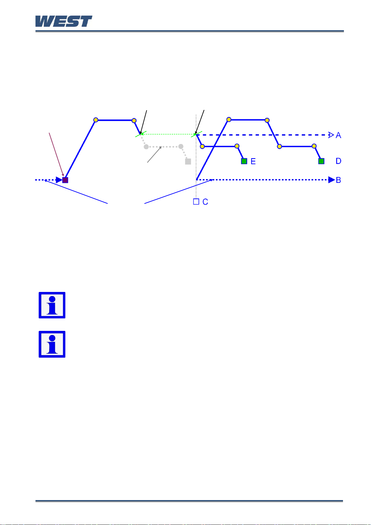
Pro-EC44 2-Loop Graphical Profile Controller & Recorder
Possible Recovery Methods:
See
note
below
A
End the profile and maintain the setpoint value(s) from the time the power failed.
B
End the profile and use Controller Setpoint value(s).
C
End the profile with the Control outputs off - setpoint value replaced by “OFF”.
D
Restart the profile again from the beginning.
E
Continue profile from the point it had reached when the power failed
Note: Recorder versions always use option E (Continue profile) if the “off time” is
less than the Profile Recovery Time setting. If the “off time” is longer, the defined
Profile Recovery Method is used.
Note: With option E, after the power returns profile bar graph resets and shows
the remaining/elapsed time for the profile only since re-starting.
Controller SP
Run
(Start-on SP)
Power off or input lost
Power / input returns
= Control Off
Planned Profile
Off Time
Power/Signal Lost Recovery Actions
If the power is cut or the input signal is lost while a profile is running, the instrument will use
the defined Profile Recovery Method once the signal / power returns. The profile recovery
method is set in the profile header.
The possible profile recovery options are explained below.
Figure 55. End, Abort and Recovery Actions
Pro-EC44 Product Manual - 59540-1 October 2013 Page 93
 Loading...