

Page 1
Industrial Controller Pro-8
West Pro-8 user manual – 59560
Page 2

BlueControl
More efficiency in engineering,
more overview in operating:
The projecting environment for the West Pro controllers
Description of symbols:
g General information
a General warning
l Attention: ESD sensitive devices
West Control Solutions
rights reserved. No part of this document may bereproduced or published in any form
All
or by any means without prior written permission from the copyright owner.
Page 3

Contents
1 Mounting .............................. 5
2 Electrical connections ....................... 7
2.1 Connecting diagram......................... 7
2.2 Connecting diagram for the options card ..............8
2.3 Terminal connection ........................ 8
3 Operation ............................. 12
3.1 Front view ............................. 12
3.2 Behaviour after power-on ..................... 13
3.3 Operating level .......................... 13
3.4 Maintenance manager / Error list ................14
3.5 Self-tuning ............................. 16
3.5.1 Preparation before self-tuning ......................16
3.5.2 Self-tuning start ............................17
3.5.3 Self-tuning cancellation ........................17
3.5.4 Acknowledgement of failed self-tuning .................17
3.5.5 Optimization after start-up or at the set-point ..............17
3.5.6 Selecting the method ( ConF/ Cntr/ tunE).............18
3.5.7 Optimization at the set-point for 3-point stepping controller ......21
3.5.8 Examples for self-tuning attempts ..................22
3.6 Manual tuning ........................... 23
3.7 Second PID parameter set .....................24
3.8 Alarm handling .......................... 25
3.9 Operating structure ........................27
4 Configuration level ........................28
4.1 Configuration survey ....................... 28
4.2 Configurations ........................... 29
4.3 Set-point processing ........................ 38
4.3.1 Set-point gradient / ramp ........................38
4.4 Pro-8 cooling functions ..........
4.4.1 Standard ( CyCl= 0 )..........................38
Pro-8
3
..............
38
Page 4

4.4.2 Switching attitude linear ( CyCl= 1 ) ................39
4.4.3 Switching attitude non-linear ( CyCl= 2 )..............39
4.4.4 Heating and cooling with constant period ( CyCl= 3 )........40
4.5 Configuration examples ...................... 41
4.5.1 On-Off controller / Signaller (inverse) .................41
4.5.2 2-point and continuous controller (inverse) ...............42
4.5.3 3-point and continuous controller ...................43
4.5.4 3-point stepping controller (relay & relay) ...............44
4.5.5 D - Y - Off controller / 2-point controller with pre-contact ......45
4.5.6 Pro-8 with measured value output .
...................
46
5 Parameter setting level ...................... 48
5.1 Parameter survey ......................... 48
5.2 Parameters ............................. 49
5.3 Input scaling ............................ 52
5.3.1 Input Inp.1 ...............................52
5.3.2 Input InP.2 ...............................52
6 Calibration level ......................... 53
7 Programmer ........................... 56
8 Special functions ......................... 57
8.1 Start-up circuit ........................... 57
8.2 Boost function ........................... 58
8.3 Pro-8 as Modbus master ......
.................
59
8.4 Linearization............................ 60
9 BlueControl ............................ 61
10 Versions .............................. 62
11 Technical data .......................... 64
12 Safety hints ............................ 67
12.1 Reset to default .......................... 69
4
Pro-8
Page 5
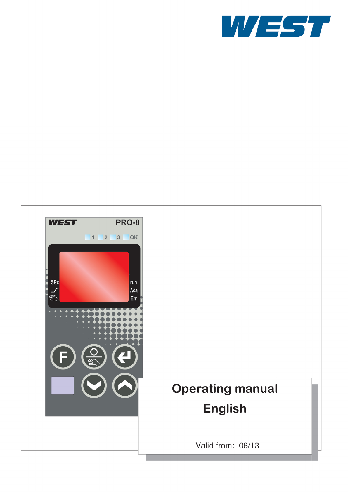
1 Mounting
oder:
*
Ü
*
Ü
96
(3.78")
48 (1.89")
min.48 (1.89")
10
(0.4")
1..10
(0.04..0.4")
118
(4.65")
45
+0,6
(1.77" )
+0.02
92
+0,8
(3.62" )
+0.03
125
126
SP.X
run
Err
Ada
è
%
max.
95% rel.
max.
60°C
0°Cmin.
Safety switches
Loc
10V i mA/Pt
U i I
Pro-8
Mounting
Safety switch:
For access to the safety switches, the controller must be withdrawn from the housing. Squeeze the top and bottom of the front bezel between thumb and forefinger
and pull the controller firmly from the housing.
Pro-8
5
Page 6

Mounting
a
Name of safety
switch
10V i mA/Pt right Current signal / Pt100 / thermocouple at
Loc open Levels as set using the BlueControl®eng. tool
U<-> I
only valid for
KS5.-1.4-.....-...
KS5.-1.5-.....-...
Position Remark Factory
setting
l
InP.1
left Voltage signal at InP.1
(default):
- Access to controller off / self-tuning / extended
operating level = enabled
- Password PASS= OFF
- Access to parameter setting level /
configuration level /
calibration level= disabled
close all levels accessible wihout restriction l
right (I) Current / logic on output 3 "OUT3" l
left (U) Voltage on output 3 "OUT3"
Safety switch 10V i mA/Pt and U<-> I always in position left or right.
Leaving the safety switch open may lead to faulty functions!
l
Caution! The unit contains ESD-sensitive components.
6
Pro-8
Page 7
Electrical connections
L
N
90...250V
24V AC/DC
mA
mA
0..10 V
HC
di1
INP1
INP2
OUT3
OUT2
OUT1
1
2
3
4
7
5
8
6
9
10
11
12
13
14
15
ab c d
U
Logic
KS 5_-1. -.....-...
KS 5_-1. -.....-...
2
3
C
N/O
N/O
C
N/O
N/C
L
N
90...250V
24V AC/DC
mA
0..10 V
di1
INP1
OUT3
OUT2
OUT1
1
2
3
4
7
5
8
6
9
10
11
12
13
14
15
ab c d
U
Logic
C
N/O
N/C
N/O
C
N/C
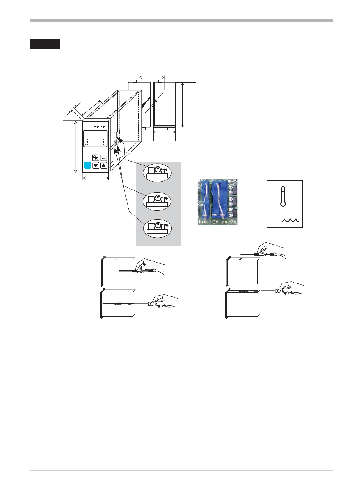
2 Electrical connections
2.1 Connecting diagram
Electrical connections for all types KS 5x-1 exept KS 5_-1_4-_ 00_ _-_ _
Electrical connections for KS 5_-1_4-_____-__
* Safety switch 10Vi mA/Pt (input INP1 current”10V” i mA/Pt/mV)
** Safety switch U i I (output OUT3 current”U” i voltage”I”)
Connecting diagram 7
Pro-8
Page 8
2.2 Connecting diagram for the options card
di2
di3
U
T
Option
RXD-B
GND
RXD-A
TXD-B
TXD-A
RS485 RS422
Modbus RTU
RGND
DATA B
DATA A
+24V DC
24V GND
1
2
3
4
7
5
8
6
9
10
11
12
13
14
15
1
3
4
5
6
7
8
9
10
11
12
13
14
15
17
(2)
(16)
OUT5
OUT6
24 VDC
24 VDC
KS5_-1..- ....-...8
Electrical connections
Pro-8
g
According to order the controller is fitted with:
flat-pin terminals combined for 1 x 6,3mm or 2 x 2,8mm to DIN 46 244
w
w
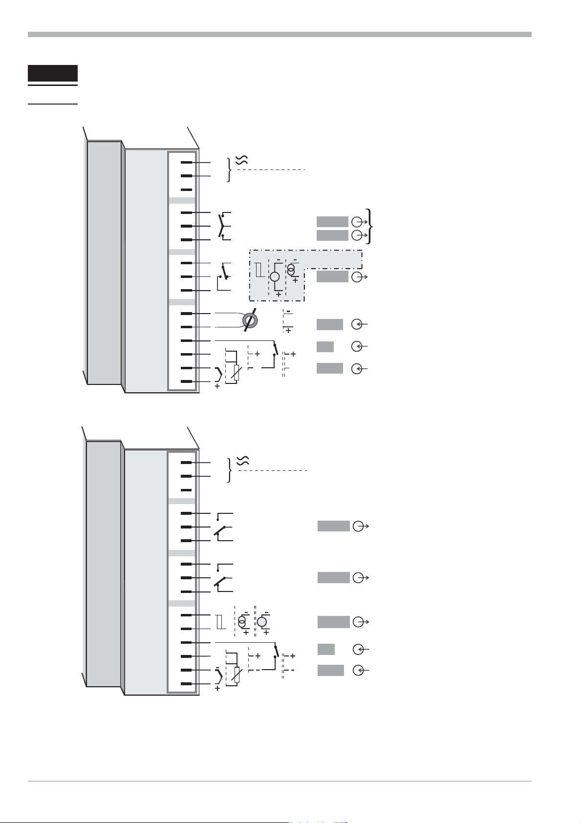
2.3 Terminal connection
or screw terminals for conductor cross section from 0,5 to 2,5mm²
On instruments with screw terminals, the stripping length must be min. 12
mm. Select end crimps accordingly.
Power supply connection 1
See chapter 11 "Technical data"
Connection of input INP1 2
Input for variable x1 (process value)
a thermocouple
b resistance thermometer (Pt100/ Pt1000/ KTY/ ...)
c current (0/4...20mA)
d voltage (0/2...10V) *Note: consider the safety switches.
8 Connecting diagram for the options card
Page 9
Electrical connections
1
2
3
4
7
5
8
6
9
10
11
12
13
14
15
L
N
Logic
+
_
SSR
1
2
3
4
7
5
8
6
9
10
11
12
13
14
15
L
N
+
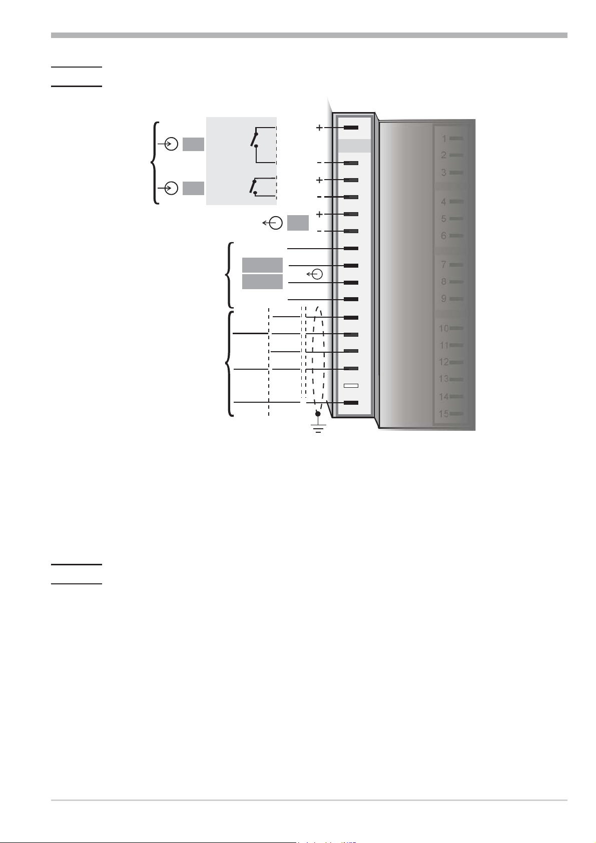
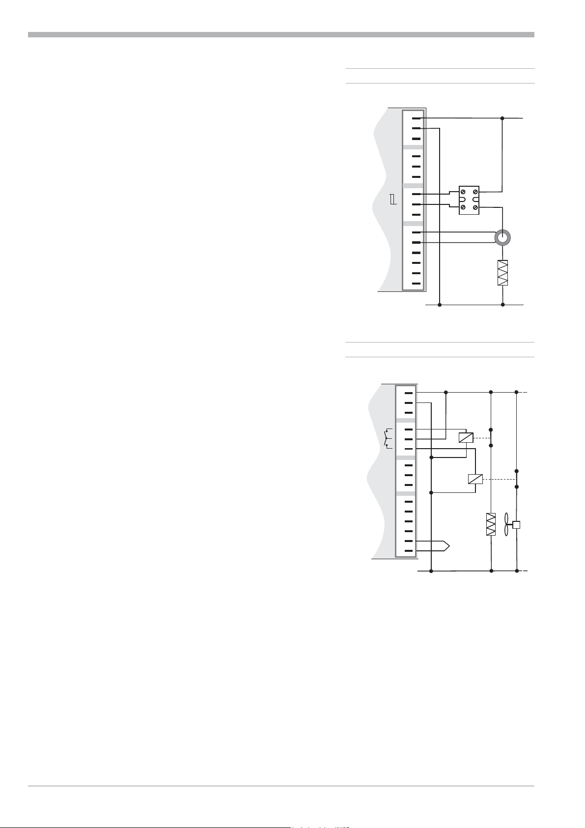
Connection of input INP2 3
3 INP2 current tansformer
Sensor type 0...50mA AC or
0/4 ... 20 mA DC for heating current input,
external set-point or
external correcting variable Y.E.
Connection of input di1 4
Digital input, configurable as a switch direct /
inverse or a push-button. ***
Connection of outputs OUT1/2 5
Relay outputs 250V/2A normally open with
common contact connection
Connection of output OUT3 6
Relay-output
KS5_-1_0-_00_ _-_ _ _ or
KS5_-1_1-_00_ _ -_ _ _
- Relay (250V/2A), potential-free changeover contact
Universal-output
5 OUT1/2 heating/cooling
KS5_-1_2-_00_ _-_ _ _or
KS5_-1_3-_00_ _-_ _ _
- Current (0/4...20mA)
- Voltage (0/2...10V)
- Transmitter power supply
- Logic (0..20mA / 0..12V)
Connection of inputs di2/3 7 (option)
Configurable as a switch direct / inverse
or as a push-button. ***
- Opto-coupler input
KS5_-1_ _-100_ _-_ _ _
Digital inputs (24VDC external)
galvanically isolated.
- Potential-free contact input
KS5_-1_ _-800_ _-_ _ _
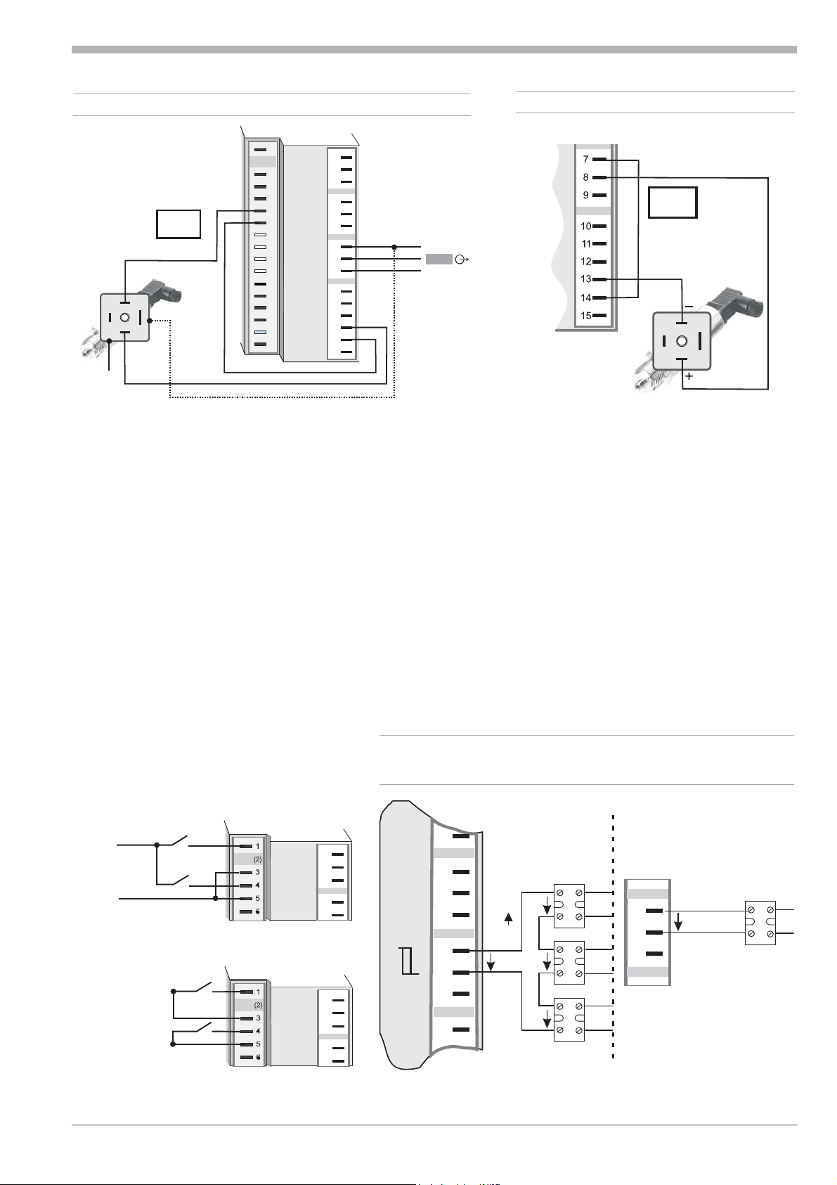
Connection of output U
8 (option)
T
Supply voltage connection for external energization
Connection of outputs OUT5/6 9
(option)
Digital outputs (opto-coupler), galvanic isolated, common positive control voltage, output rating: 18...32VDC
Terminal connection 9
Connection of bus interface 0 (option)
RS422/485 interface with Modbus RTU protocol
*** Adjustment is possible only in common for all digital inputs.
Pro-8
Page 10
Electrical connections
1
2
3
K
+
-
+
-
13V
22mA
1
3
4
5
6
7
8
9
10
11
12
13
14
15
17
(2)
(16)
1
2
3
4
7
5
8
6
9
10
11
12
13
14
15
1
2
3
K
+
-
+
-
+
-
17,5V
22mA
OUT3
J
Option KS5_-1_ _-100 _ _-_ _ _
1
2
3
4
5
+24VDC
5mA
5mA
0V
Option KS5_-1_ _-800 _ _-_ _ _
1
2
3
4
5
7
8
9
7
8
9
3
4
7
5
8
6
9
10
+
_
SSR
+
_
SSR
+
_
SSR
Series connection
Parallel connection
+
_
SSR
7
8
9
Logic
4V
4V
4V
12V
I =22mA
max
I =22mA
max
12V
8 2-wire transmitter supply with U
Connection of outputs OUT1 ! and OUT2 "
Relay-output KS5_-1_4-_00_ _-_ _ _ and KS5_-1_5-_00_ _-_ _ _
- Relay (250V/2A), potentialfree changeover contact
Connection of output OUT3 §
T
6 OUT3 transmitter supply
Universal output KS5_-1_4-_00_ _-_ _ _and KS5_-1_5-_00_ _- ___
Note:
Mind the safety switch.
- current (0/4...20mA)
- voltage(0/2...10V)
- Transmitter power supply
- Logic (0..20mA / 0..12V)
a
The analog outputs OUT3 and transmitter supply voltage UTare connected to
different voltage potentials. For this reason, an external galvanic connection of
OUT3 and U
7 Connection of inputs di 2/3
Pro-8
is not permissible for analog outputs.
T
6 OUT3 as logic output with solid-state relay
(series and parallel connection)
10 Terminal connection
Page 11
Electrical connections
12
13
14
15
17
(16)
11
12
13
14
15
10
12
13
14
15
17
(16)
11
12
13
14
15
10
12
13
14
15
17
(16)
11
12
13
14
15
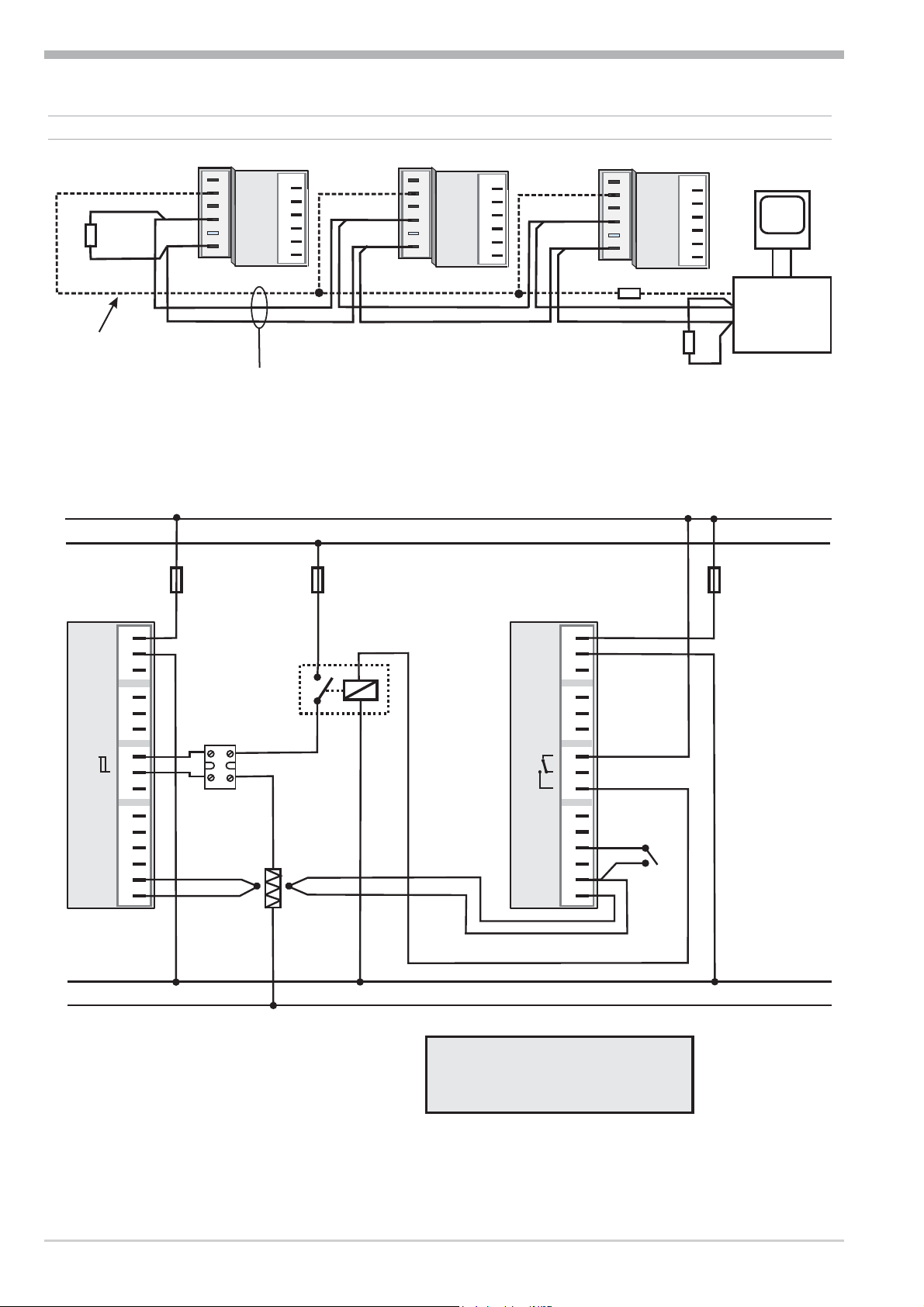
RGND RGND
RGND
RT
converter
RS485-RS232
PC
DATA A
DATA B
DATA A
DATA B
DATA A
DATA B
J
max. 1000m
”Twisted Pair”
10
RT
R=100 Ohm
RGND connection optional
R = 120...200 OhmT
R = 120...200 OhmT
1
2
3
4
7
5
8
6
9
10
11
12
13
14
15
Logic
+
_
L1
L2
N1
N2
fuse
1
2
3
4
7
5
8
6
9
10
11
12
13
14
15
TB 40-1
Temperature limiter
1
KS 5_-1
SSR
reset
contactor
heating
1 TB 40-1 Temperature limiter
Standard version (3 relays):
TB40-100-0000D-000
other versions on requestr
+
+
fuse
fuse
0 RS485 interface (with RS232-RS485 interface converter) ****
****see Interface description Modbus RTU 9499-040-63611 .
KS5_-1_2-_00_ _-_ _ _. connecting example:
systems where overtemperature implies a fire hazard or
other risks.
a
CAUTION: Using a temperature limiter is recommendable in
Terminal connection 11
Pro-8
Page 12
Operation
125
126.
SP.x
run
Err
Ada
123OK
3
1
2
3
4
0
5
!
6
"
7
8
§
9
$
%
è
&
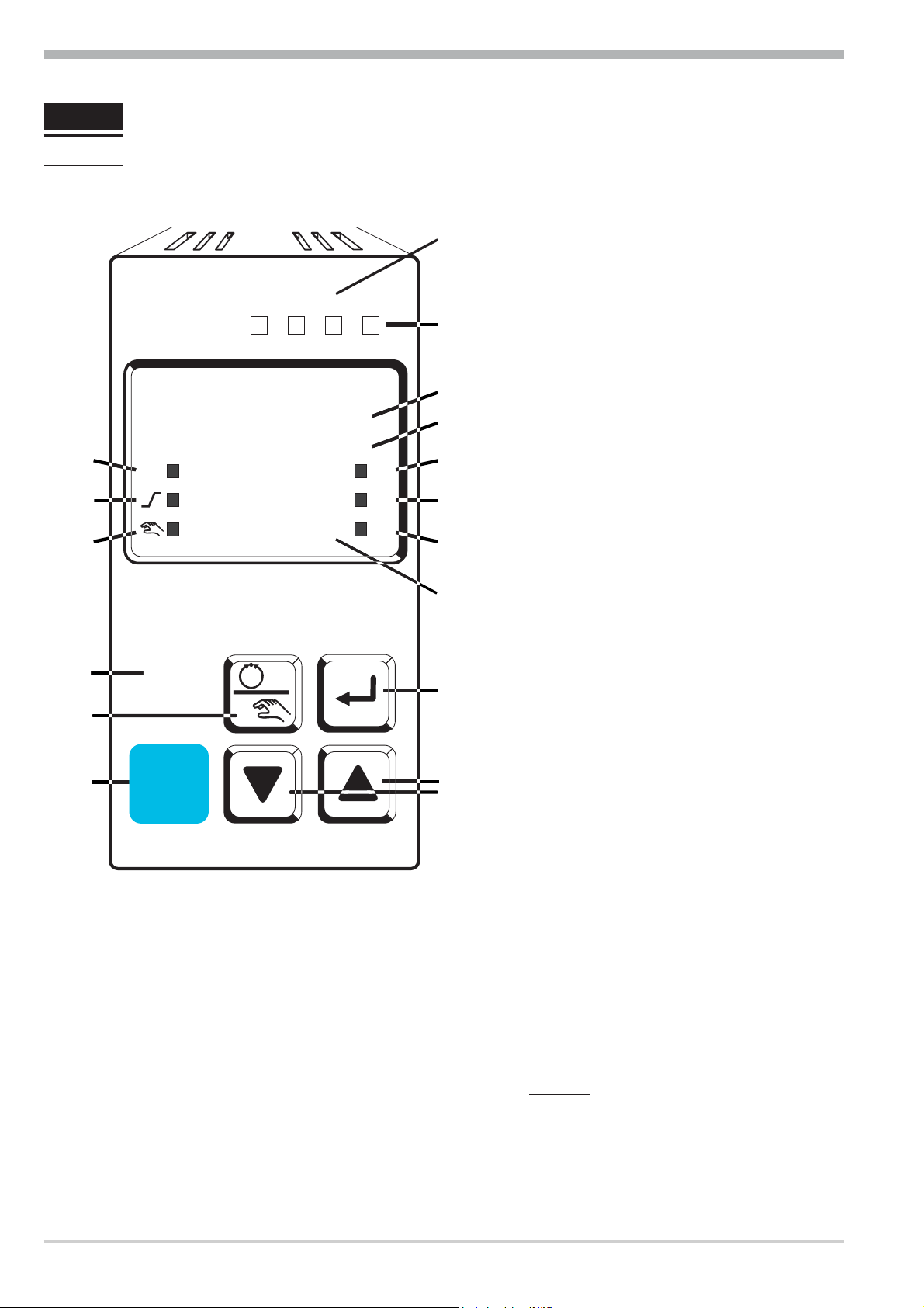
3 Operation
3.1 Front view
LED colours:
LED 1, 2, 3: yellow
LED OK: green
other LEDs: red
1 For function states /
see LED assignment
(Conf/othr/LEd)
2 Lit with limit value 1
( PArA / Lim ) not exceeded
3 Process value display
4 Set-point, controller output
5 Signals ConF and PArA level
6 Programmer running
7 Self-tuning active
8 Entry in error list
9 Set-point SP.2 or SP.E is
effective
0 Set-point gradient effective
! Manual/automatic switch-over:
Off: Automatic
On: Manual
(changing possible)
Blinks: Manual
(changing not possible
(r ConF/ Cntr/ MAn)
" Enter key:
calls up extended operating
level / error list
§ Up/down keys:
changing the set-point or the
controller output value
$ Manual mode /spec. function
(® ConF / LOGI )
% PC connection for
BlueControl (engineering
tool)
& Freely programmable function
key
In the upper display line, the process value is always displayed. At parameter,
configuration, calibration as well as extended operating level, the bottom display
line changes cyclically between parameter name and parameter value.
g
Front view 12
Pro-8
Page 13
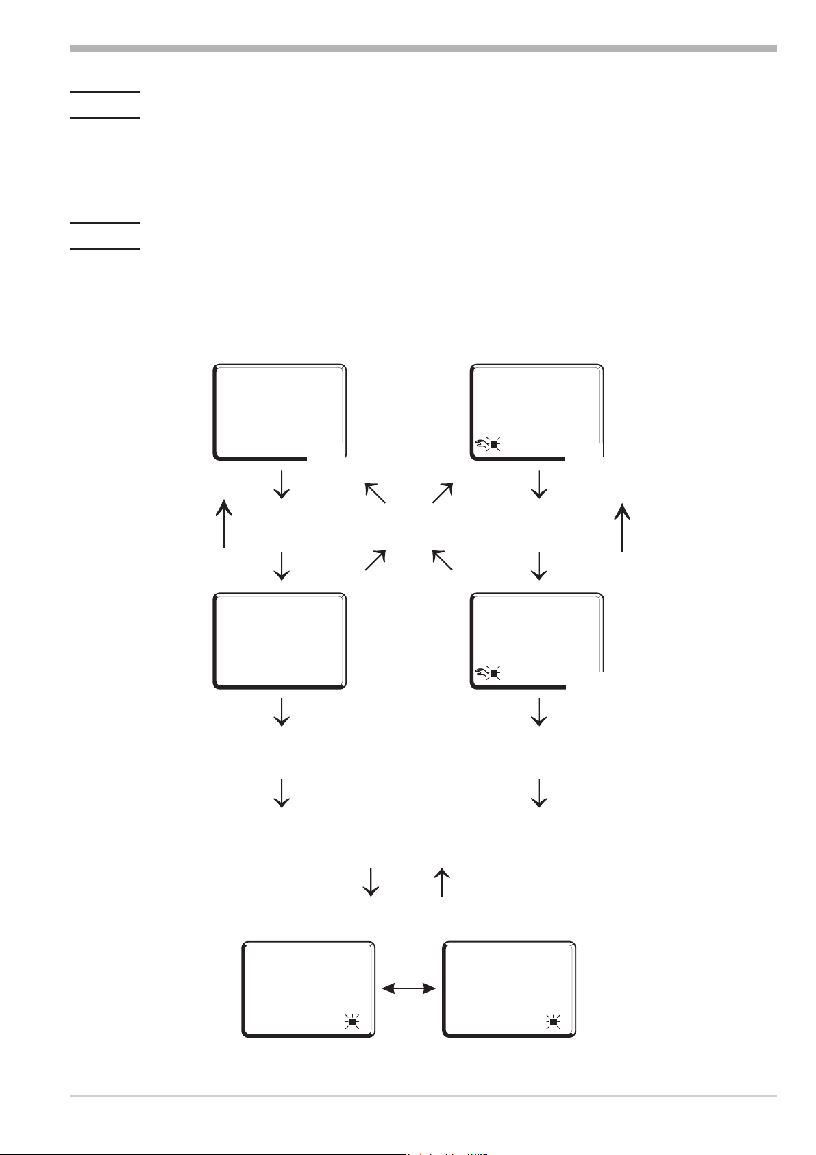
3.2 Behaviour after power-on
125
126
y21
126
y21
126
Ò
Ò
Ù
Ù
Ù
Ù
125
126
Automatic
Extended operating level
Manual
i
i
È
Ì
È
Ì
È
Ì
only
display
126
FbF.1
Err
2
126
Err
switching
display
Errorliste (if error exists)
time
out
time
out
time
out
After supply voltage switch-on, the unit starts with the operating level.
The unit is in the condition which was active before power-off.
If the controller was in manual mode before power-off, the controller starts with
the last correcting value after switching on again.
3.3 Operating level
The content of the extended operating level is determined by means of BlueControl (engineering tool). Parameters which are used frequently or the display of
which is important can be copied to the extended operating level.
Operation
Pro-8
13 Behaviour after power-on
Page 14
Operation
125
126
SP.x
run
Ada
Err
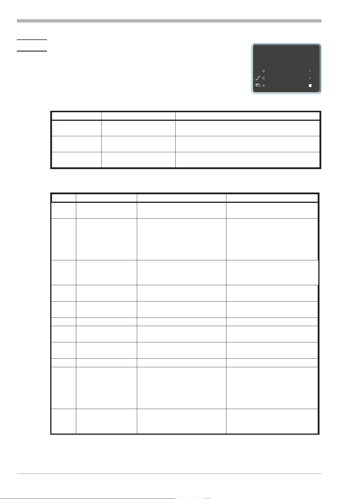
3.4 Maintenance manager / Error list
With one or several errors, the extended operating level always starts with the error list. Signalling an actual entry in
the error list (alarm, error) is done by the Err LED in the
display. This is applicable only, if at least one limit value
function, the loop alarm or the heating current alarm is activated. For display of the error list, press Ù twice.
Err LED status Signification Proceed as follows
blinks
(Status 2)
lit
(Status1)
off
(Status 0)
Alarm due to existing
error
Error removed,
Alarm not acknowledged
No error,
all alarm entries deleted
Determine the error type in the error list after
removing the error the device changes to Status1
Acknowledge the alarm in the error list pressing key
È or Ì the alarm entry is deleted (Status 0).
not visible, exept when ackowledging
Error list:
Name
E.1
Internal error,
cannot be removed
E.2
Internal error, can be
reset
E.4
Hardware error Codenumber and hardware are
FbF.1
Sht.1
POL.1
FbF.2
Sht.2
POL.2
HCA
SSr
Sensor break INP1 Sensor defective
Short circuit INP1 Sensor defective
INP1polarity error Faulty cabling Reverse INP1 polarity
Sensor break INP2 Sensor defective
Short circuit INP2 Sensor defective
INP2 polarity Faulty cabling Reverse INP2 polarity
Heating current
alarm (HCA)
Heating current short
circuit (SSR)
Description Cause Possible remedial action
E.g. defective EEPROM Contact PMA service
Return unit to our factory
e.g. EMC trouble Keep measurement and power
supply cables in separate runs
Ensure that interference
suppression of contactors is
provided
Contact PMA service
not identical
Electronic-/Optioncard must be
exchanged
Replace INP1 sensor
Faulty cabling
Check INP1 connection
Replace INP1 sensor
Faulty cabling
Check INP1 connection
Replace INP2 sensor
Faulty cabling
Check INP2 connection
Replace sensor INP2
Faulty cabling
Heating current circuit
interrupted, I< HC.A or I>
Check INP2 connection
Check heating current circuit
If necessary, replace heater band
HC.A (dependent of
configuration)
Heater band defective
Current flow in heating circuit
at controller off
SSR defective
Check heating current circuit
If necessary, replace solid-state
relay
Maintenance manager / Error list 14
Pro-8
Page 15
Operation
g
Name
LooP
Description Cause Possible remedial action
Control loop alarm
(LOOP)
Input signal defective or not
connected correctly
Output not connected correctly
Check heating or cooling circuit
Check sensor and replace it, if
necessary
Check controller and switching
device
AdA.H
Self-tuning heating
alarm
See Self-tuning heating error
status
see Self-tuning heating error
status
(ADAH)
AdA.C
Self-tuning heating
alarm cooling
See Self-tuning cooling error
status
see Self-tuning cooling error
status
(ADAC)
LiM.1
Lim.2
Lim.3
Inf.1
Inf.2
stored limit alarm 1 adjusted limit value 1 exceeded check process
stored limit alarm 2 adjusted limit value 2 exceeded check process
stored limit alarm 3 adjusted limit value 3 exceeded check process
time limit value
message
duty cycle message
(digital ouputs)
adjusted number of operating
hours reached
adjusted number of duty cycles
reached
application-specific
application-specific
Saved alarms (Err-LED is lit) can be acknowledged and deleted with the digital
input di1/2/3, the è-key or the Ò-key or the.
Configuration, see page 36: ConF / LOGI / Err.r
g
If an alarm is still valid that means the cause of the alarm is not removed so far
(Err-LED blinks), then other saved alarms can not be acknowledged and deleted.
Not applicable to heating current alarm.
Error status:
Self-tuning heating ( ADA.H) and cooling ( ADA.C) error status:
Error status
0
3
4
5
6
7
8
9
No error
Faulty control action Re-configure controller (inverse i direct)
No response of process
variable
Low reversal point Increase ( ADA.H) max. output limiting Y.Hi or
Danger of exceeded set-point
(parameter determined)
Output step change too small
{y > 5%)
(
Set-point reserve too small Increase set-point (invers), reduce set-point (direct)
Impulse tuning failed The control loop is perhaps not closed: check sensor,
Description Behaviour
The control loop is perhaps not closed: check sensor,
connections and process
decrease ( ADA.C) min. output limiting Y.Lo
If necessary, increase (inverse) or reduce (direct)
set-point
Increase ( ADA.H) max. output limiting Y.Hi or
reduce ( ADA.C) min. output limiting Y.Lo
or increase set-point range
(r PArA / SEtp / SP.LO and SP.Hi )
connections and process
Pro-8
15 Maintenance manager / Error list
Page 16

Operation
3.5 Self-tuning
For determination of optimum process parameters, self-tuning is possible.
After starting by the operator, the controller makes an adaptation attempt, whereby the process characteristics are used to calculate the parameters for fast line-out
to the set-point without overshoot.
The following parameters are optimized when self-tuning:
Parameter set 1:
3.5.1
Pb1
ti1
td1
t1
Pb2
ti2
td2
t2
Parameterset 2: according to Parameterset 1 (see page 24)
Proportional band 1 (heating) in engineering units [e.g. °C]
Integral time 1 (heating) in [s] r only, unless set to OFF
Derivative time 1 (heating) in [s] r only, unless set to OFF
Minimum cycle time 1 (heating) in [s]. This parameter is optimized only, unless
parameter Cntr/Adt0 was configured for “no self-tuning” using BlueControl
Proportional band 2 (cooling) in engineering units [e.g. °C]
Integral time 2 (cooling) in [s] r only, unless set to OFF
Derivative time 2 (cooling) in [s] r only, unless set to OFF
Minimum cycle time 2 (cooling) in [s]. This parameter is optimized only, unless
parameter Cntr/Adt0 was configured for “no self-tuning”using BlueControl
Preparation before self-tuning
As a prerequisite of process evaluation, a stable condition is required. For this
w
reason, the controller waits, until the process has reached a stable condition
after self-tuning start.
The rest condition is considered as reached, when the process value oscillation is smaller than ± 0,5% of (rnG.H - rnG.L). The limits of the control range
must be adjusted for the controller operating range, i.e. rnG.L and rnG.H
must be adjusted to the limits within which control must take place (ConfigurationrControllerrspan start and end of control range) ConFrCntrr
rnG.L and rnG.H
®
®
For starting the self-tuning after start-up, a clearance of 10% of (SP.LO...
w
SP.Hi) is required. As the values PArA/SEtp/SP.LO and
PArA/SEtp/SP.Hi mustl always be within the control range, no restriction
is applicable if these values are adjusted correctly.
Determine which parameter set must be optimized.
w
-The currently effective parameter set is optimized.
r activate the corresponding parameter set (1 or 2).
Determine which parameter must be optimized (see the list given above)
w
Select the method for self-tuning
w
See Chapter 3.5.6
- Step attempt after start-up
- Pulse attempt after start-up
- Optimization at the set-point
Self-tuning 16
Pro-8
Page 17
3.5.2 Self-tuning start
125
126
SP.x
run
Ada
Err
Operation
g
3.5.3
Self-tuning start can be disabled using BlueControl®(engineering tool)
(Conf/Othr/IAdA).
Starting the self-tuning:
Self-tuning is started by pressing the Ù and È keys simultaneously, or via the
interface. If parameter Conf/Cntr/Strt is set to 1 self-tuning starts also after power-on and when detecting process value oscillations.
Self-tuning status display
Ada-LED-Status Meaning
blinks Waiting until process is at rest
lit seft tuning running
off self tuning not active e.g. ready
Self-tuning cancellation
By the operator:
w
Self-tuning is cancelled by pressing the Ù and È keys simultaneously.
Switching over to manual operation also causes cancellation of the self-tuning procedure.
After self-tuning cancellation, the controller continues operating using the parameters valid prior to self-tuning start.
3.5.4
By the controller:
w
If the Err LED starts blinking during self-tuning, successful self-tuning is prevented due to the control conditions. In this case, self-tuning was cancelled
by the controller. The controller continues operating using the parameters valid before self-tuning start.
If the self-tuning method with step attempt was used and
started from the manual mode, the controller uses the last valid correcting variable after self-tuning start, until the self-tuning error message is acknowledged. Subsequently, the controller continues operating using the parameters
valid before self-tuning start.
Causes of cancellation:
® Page 8: " Self-tuning heating (ADA.H) and cooling (ADA.C) error status"
self-tuning was
Acknowledgement of failed self-tuning
When pressing the Ù key, the controller switches over to correcting variable dis-
play (Y ....). After pressing the Ù key again, the controller goes to the error list
of the extended operating level. The error message can be acknowledged by switching the message to 0 using the D or the I key.
After acknowledging the error message, the controller continues operating in the
automatic mode, using the parameters valid prior to self-tuning start.
Pro-8
17 Self-tuning
Page 18

Operation
3.5.5 Optimization after start-up or at the set-point
The two methods are optimization after start-up and at the set-point.
As control parameters are always optimal only for a limited process range, various methods can be selected dependent of requirements. If the process behaviour
is very different after start-up and directly at the set-point, parameter sets 1 and 2
can be optimized using different methods. Switch-over between parameter sets
dependent of process status is possible (see page ).
Optimization after start-up: (see page 18)
Optimization after start-up requires a certain separation between process value
and set-point. This separation enables the controller to determine the control parameters by evaluation of the process when lining out to the set-point.
This method optimizes the control loop from the start conditions to the set-point,
whereby a wide control range is covered.
We recommend selecting optimization method “Step attempt after start-up”
with tunE = 0 first. Unless this attempt is completed successfully, we then recommend a “Pulse attempt after start-up”.
3.5.6
Optimization at the set-point: (see page 19)
For optimizing at the set-point, the controller outputs a disturbance variable to the
process. This is done by changing the output variable shortly. The process value
changed by this pulse is evaluated. The detected process parameters are converted into control parameters and saved in the controller.
This procedure optimizes the control loop directly at the set-point. The advantage
is in the small control deviation during optimization.
Selecting the method ( ConF/ Cntr/ tunE)
Selection criteria for the optimization method:
Step attempt after start-up Pulse attempt after start-up Optimization at the set-point
tunE =0
tunE =1
tunE =2
sufficient set-point reserve is
provided
sufficient set-point reserve is
provided
Only step attempt after start-up
required
Sufficient set-point reserve:
inverse controller:(with process value < set-point- (10% of rnGH - rnGL)
direct controller: (with process value > set-point + (10% of rnGH - rnGL)
sufficient set-point reserve is not
provided
sufficient set-point reserve is not
provided
inverse controller:
process value is (10% of rnGH - rnGL) below the set-point
direct controller:
process value is (10% of rnGH - rnGL) above the set-point
Self-tuning 18
Pro-8
Page 19

Step attempt after start-up
Condition: - tunE = 0 and sufficient set-point reserve provided or
- tunE =2
The controller outputs 0% correcting variable or Y.Lo and waits, until the process
is at rest (see start-conditions on page 8).
Subsequently, a correcting variable step change to 100% or Y.Hi is output.
The controller attempts to calculate the optimum control parameters from the process response. If this is done successfully, the optimized parameters are taken
over and used for line-out to the set-point.
With a 3-point controller, this is followed by “cooling”.
After completing the 1st step as described, a correcting variable of -100% or
Y.Lo (100% cooling energy) is output from the set-point. After successfull determination of the “cooling parameters”, line-out to the set-point is using the optimized parameters.
Operation
Pulse attempt after start-up
Condition: - tunE = 1 and sufficient set-point reserve provided.
The controller outputs 0% correcting variable or Y.Lo and waits, until the process
is at rest (see start conditions page 8)
Subsequently, a short pulse of 100% or Y.Hi is output (Y=100%) and reset.
The controller attempts to determine the optimum control parameters from the
process response. If this is completed successfully, these optimized parameters
are taken over and used for line-out to the set-point.
With a 3-point controller, this is followed by “cooling”.
After completing the 1st step as described and line-out to the set-point, correcting
variable "heating" remains unchanged and a cooling pulse (100% cooling energy)
is output additionally. After successful determination of the “cooling parameters”, the optimized parameters are used for line-out to the set-point.
Optimization at the set-point
Conditions:
A sufficient set-point reserve is not provided at self-tuning start (see page 18).
w
tunE is0or1
w
With Strt = 1 configured and detection of a process value oscillation by
w
more than ± 0,5% of (rnG.H - rnG.L) by the controller, the control parameters are preset for process stabilization and the controller realizes an optimiza-
tion at the set-point (see figure “Optimization at the set-point”).
Pro-8
when the step attempt after power-on has failed
w
with active gradient function ( PArA/ SETP/ r.SP¹ OFF), the set-point
w
gradient is started from the process value and there isn't a sufficient set-point
reserve.
19 Self-tuning
Page 20
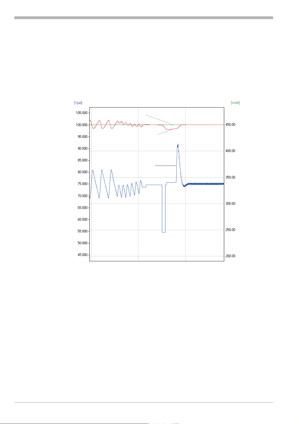
Operation
set-point
process value
correcting
variable
Optimization-at-the-set-point procedure:
The controller uses its instantaneous parameters for control to the set-point. In lined out condition, the controller makes a pulse attempt. This pulse reduces the
correcting variable by max. 20% 1, to generate a slight process value undershoot. The changing process is analyzed and the parameters thus calculated are recorded in the controller. The optimized parameters are used for line-out to the
set-point.
Optimization at the set-point
With a 3-point controller, optimization for the “heating“ or “cooling” parameters
occurs dependent of the instantaneous condition.
While the controller is in the "heating-phase" the heating-parameters are determined. If the controller is in the "cooling-phase" the cooling-parameters are
determined.
1 If the correcting variable is too low for reduction in lined out condition it is
increased by max. 20%.
Self-tuning 20
Pro-8
Page 21
Operation
3.5.7 Optimization at the set-point for 3-point stepping controller
As position feedback is not provided, the controller calculates the actuator position internally by adjusting an integrator with the adjusted actuator travel time.
For this reason, precise entry of the actuator travel time (tt), as time between
stops is highly important.
Due to position simulation, the controller knows whether an increased or reduced
pulse must be output. After supply voltage switch-on, position simulation is at
50%. When the motor actuator was varied by the adjusted travel time in one go,
internal calculation occurs, i.e. the position corresponds to the simulation:
Simulation real position
Pro-8
Internal calculation tt
Internal calculation always occurs, when the actuator was varied by travel time
tt in one go
, independent of manual or automatic mode. When interrupting the
variation, internal calculation is cancelled. Unless internal calculation occurred
already after self-tuning start, it will occur automatically by closing the actuator
once.
Unless the positioning limits were reached within 10 hours, a significant deviation between simulation and actual position may have occurred. In this case, the
controller would realize minor internal calculation, i.e. the actuator would be closed by 20 %, and re-opened by 20 % subsequently. As a result, the controller
knows that there is a 20% reserve for the attempt.
21 Self-tuning
Page 22
Operation
t
2
100%
Y
0%
X
W
Star t r
1
3
t reversal point
blinks
t
100%
Y
0%
X
W
start r
1
2
t reversal point
blinks
t
2
100%
Y
0%
X
W
1
3
blinks
4
r
t
Start r
t
+100%
Y0%
-100%
X
W
t reversal
point
Start r
1
2
3
4
5
rt
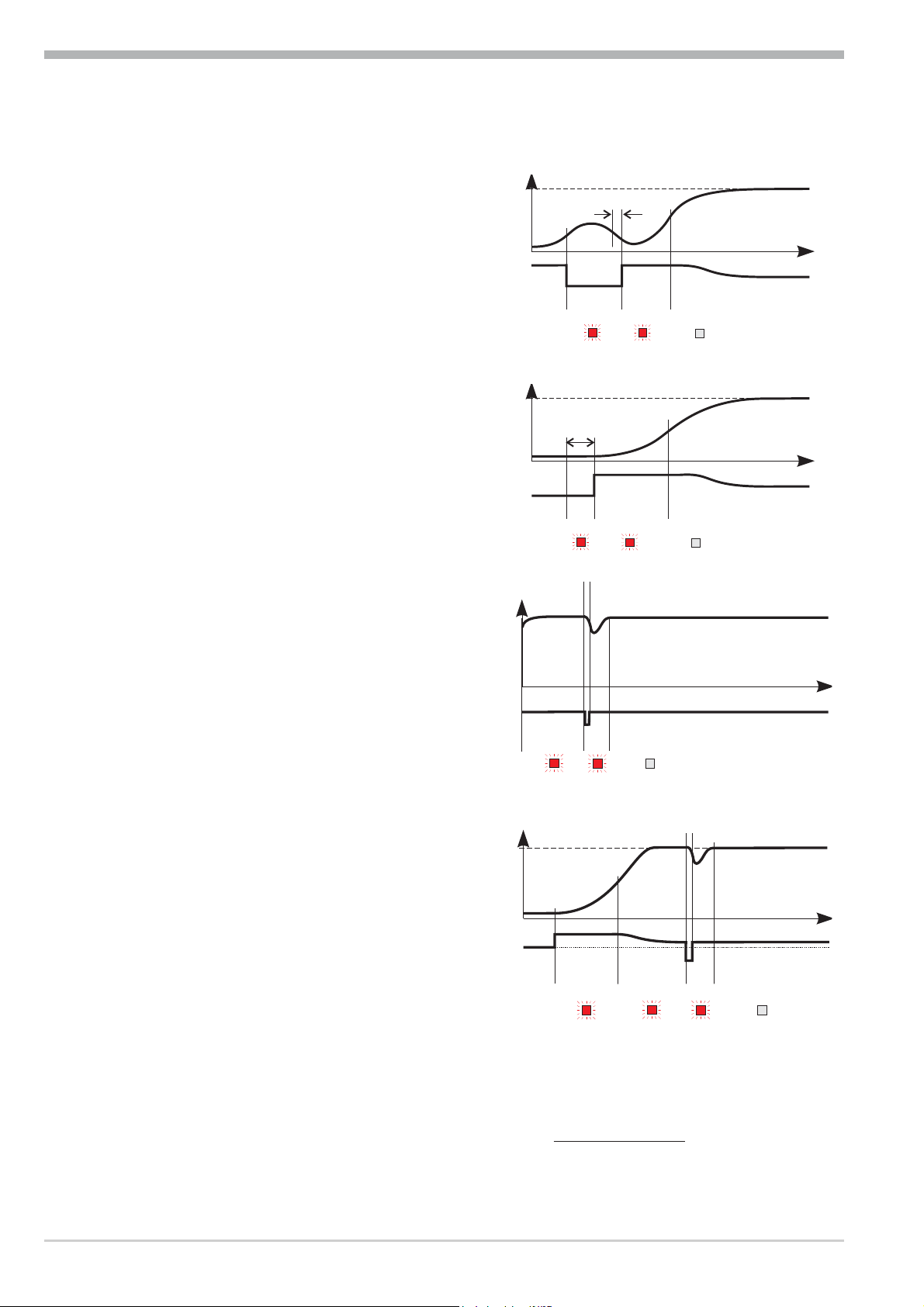
3.5.8 Examples for self-tuning attempts
(controller inverse, heating or heating/cooling)
Start: heating power switched on
Heating power Y is switched off (1).
When the change of process value X
was constant during one minute (2),
the power is switched on (3).
At the reversal point, the self-tuning
attempt is finished and the new parameter are used for controlling to
set-point W.
Start: heating power switched off
The controller waits 1,5 minutes (1).
Heating power Y is switched on (2).
At the reversal point, the self-tuning
attempt is finished and control to the
set-point is using the new parameters.
Self-tuning at the set-point a
The process is controlled to the
set-point. With the control deviation
constant during a defined time (1),
the controller outputs a reduced correcting variable pulse (max. 20%)
(2). After determination of the control parameters using the process characteristic (3), control is started using
the new parameters (4).
Three-point controller a
The parameter for heating and cooling
are determined in two attempts. The heating power is switched on (1). Heating
parameters Pb1, ti1, td1 and t1
are determined at the reversal point. The
process is controlled to the set-point (2).
With constant control deviation, the controller provides a cooling correcting variable pulse (3). After determining its
cooling parameters Pb2, ti2, td2
and t2 (4) from the process characteristics , control operation is started using the new
parameters (5).
a
During phase 3, heating and cooling are done simultaneously!
Self-tuning 22
Pro-8
Page 23

3.6 Manual tuning
Tu
Tg
t
x
y
100%
0%
t
Y
h
X
max
{X
{t
The optimization aid should be used with units on which the control parameters
shall be set without self-tuning.
For this, the response of process variable x after a step change of correcting variable y can be used. Frequently, plotting the complete response curve (0 to
100%) is not possible, because the process must be kept within defined limits.
Values T
sponse) can be used to determine the maximum rate of increase v
and x
g
(step change from 0 to 100 %) or Dt and Dx (partial step re-
max
.
max
Operation
Pro-8
y = correcting variable
Y
= control range
h
Tu = delay time (s)
Tg = recovery time (s)
X
V
= maximum process value
max
{{x
=
t
max
Xmax
=
Tg
= max. rate of increase of process value
The control parameters can be determined from the values calculated for delay time T
maximum rate of increase v
formulas given below. Increase Xp, if line-out to the set-point oscillates.
max
, control range Xhand characteristic K according to the
,
u
23 Manual tuning
Page 24

Operation
Formulas
K = Vmax * Tu controller behavior Pb1 [phy. units] td1 [s] ti1 [s]
PID 1,7*K 2*Tu 2*Tu
With 2-point and
3-point controllers,
the cycle time must be
adjusted to
t1 / t2 £ 0,25 * Tu
PD 0,5 * K Tu OFF
PI 2,6 * K OFF 6*Tu
PKOFF OFF
3-point-stepping 1,7 * K Tu 2 * Tu
Parameter adjustment effects
Parameter Control Line-out of disturbances Start-up behaviour
Pb1 higher increased damping slower line-out slower reduction of duty cycle
lower reduced damping faster line-out faster reduction of duty cycle
td1 higher reduced damping faster response to disturbances faster reduction of duty cycle
lower increased damping slower response to disturbances slower reduction of duty cycle
ti1 higher increased damping slower line-out slower reduction of duty cycle
lower reduced damping faster line-out faster reduction of duty cycle
3.7 Second PID parameter set
The process characteristic is frequently affected by various factors such as process value, correcting variable and material differences.
To comply with these requirements, the controller can be switched over between
two parameter sets. Parameter sets PArA and PAr.2 are provided for heating
and cooling.
Dependent of configuration, switch-over to the second parameter set
( ConF/LOG/Pid.2) is via key è , one of digital inputs di1, di2, di3,
or interface (OPTION).
g
Self-tuning is always done using the active parameter set, i.e. the second
parameter set must be active for optimizing.
Second PID parameter set 24
Pro-8
Page 25

Operation
H.1
HYS.1
InL.1
InH.1
0
I
HYS.1
H.1
InL.1
InH.1
SP
I
0
L.1
HYS.1
InL.1
InH.1
SP
I
0
L.1
HYS.1
InL.1
InH.1
I
0
L.1
HYS.1 HYS.1
H.1
InL.1
InH.1
I
0
L.1
HYS.1
HYS.1
H.1
InL.1
InH.1
SP
2
2
I
0
3.8 Alarm handling
Max. three alarms can be configured and assigned to the individual outputs. Generally, outputs OuT.1... OuT.6 can be used each for alarm signalling. If more
than one signal is linked to one output the signals are OR linked. Each of the 3 limit values Lim.1 … Lim.3 has 2 trigger points H.x (Max) and L.x (Min), which
can be switched off individually (parameter = “OFF”). Switching difference
HYS.x of each limit value is adjustable.
Ü Operaing principle absolut alarm
L.1 = OFF
H.1 = OFF
* Operating principle relative alarm
L.1 = OFF
H.1 = OFF
1: normally closed (ConF/ Out.x/O.Act=1) (See examples)
2: normally open (ConF/ Out.x/O.Act= 0) (The output relay action is inverted)
g
The allocation of the device's LEDs is not invertable and must be considered
separately.
Pro-8
25 Alarm handling
Page 26

Operation
g
The variable to be monitored can be selected separately per configuration for
each alarm.
The following variables are available ( ConF / Lim / Src .x):
Variable (Src .x) Remark Alarm type
Process value Absolute
Control deviationxwProcess value - effective set-point. The effective set-point Weff
is used. E.g with a ramp, this is the changing set-point rather
than the target set-point.
Control deviation
xw + suppression
after start-up or
set-point change
with time limit
Effective set-point
Weff
Correcting
variable y
Deviation from SP
internal
The alarm output is suppressed after switch-on or after a
set-point change, until the process value is within the limits
for the first time. At the latest after elapse of time 10 x ti1
the alarm is activated (ti1 = integral time 1; parameter r
Cntr). If ti1 is switched off (ti1 = OFF), this is
considered as Î , i.e. the alarm is not activated before the
process value was within the limits once.
The effective set-point Weff for control. Absolute
y = controller output signal Absolute
Process value - internal set-point. The internal set-point is
used. E.g. with a ramp, this is the target set-point instead of
the varying effective set-point Weff.
Relative
Relative
Relative
g
Control deviation
xw + suppression
after start-up or
set-point change
without time limit
After switch-on or after a set-point change, the alarm output
is suppressed , until the process value is within the limits for
the first time.
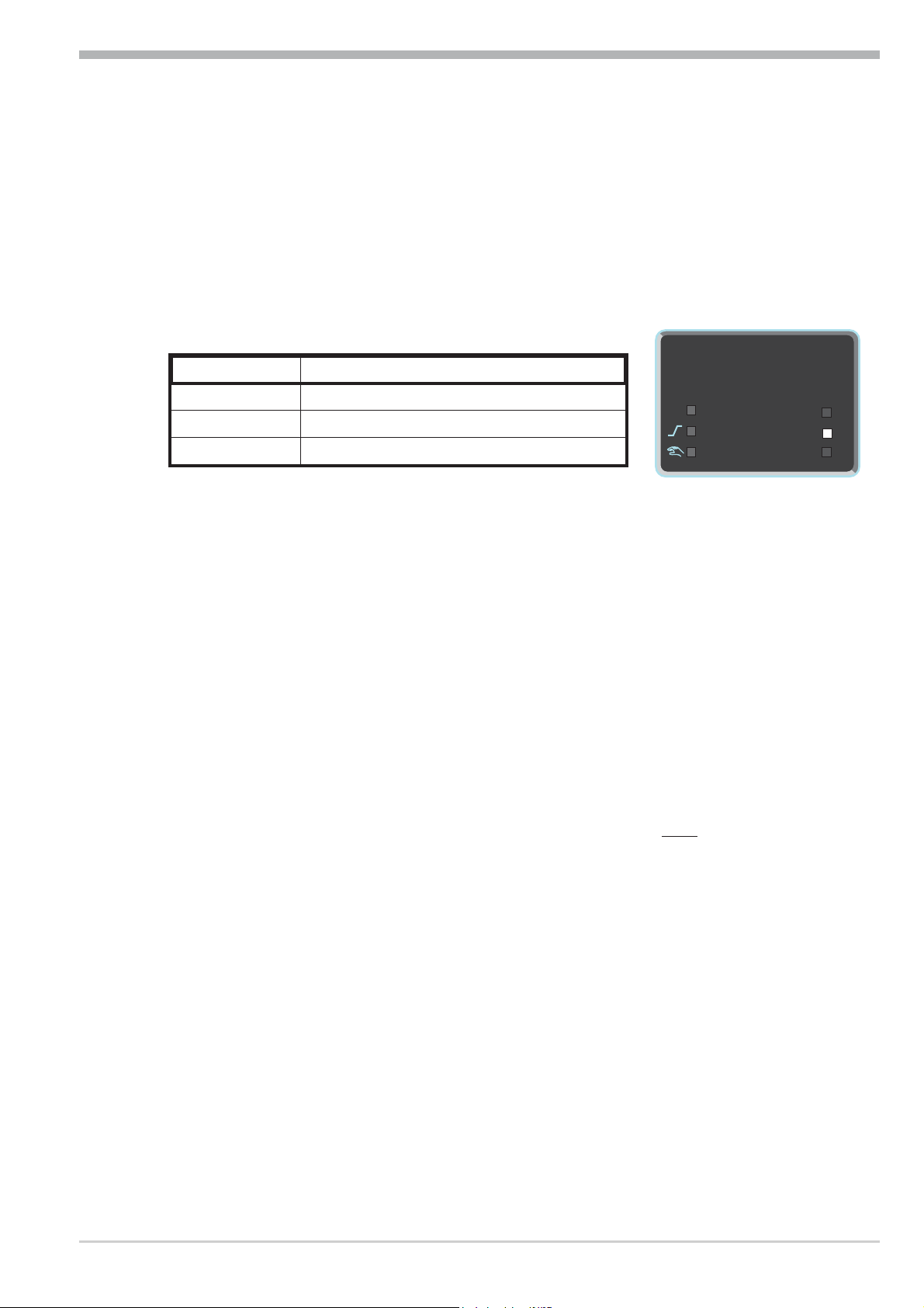
During alarm configuration, the following functions can be selected
( ConF / Lim / Fnc.x):
Function (Fnc.x) Remark
Switched off No limit value monitoring.
Measured value Process value monitoring. When exceeding the limit, an alarm is
generated.The alarm is reset automatically, when the process value is "within
the limits" (including hysteresis) again.
Measured value +
latch
Process value monitoring + latching of the alarm condition. When exceeding
the limit value, an alarm is output. A latched alarm persists, until it is reset
manually.
Relative
Alarm handling 26
Pro-8
Page 27

3.9 Operating structure
Ù
Ù
Ù
Ù
End
126
CAL
126
ConF
126
125
126
PArA
126
Ù
Ì
Ì
Ì
3sec.
PASS
PASS
PASS
PASS
After supply voltage switch-on, the controller starts with the operating levels.
The controller status is as before power off.
Operation
g
g
g
PArA - level: At PArA - level, the right decimal point of the upper
display line is lit continuously.
ConF - level: At ConF - level, the right decimal point of upper
display line blinks.
When safety switch Loc is open, only the levels enabled by means of BlueControl
word adjusted by means of BlueControl (engineering tool). Individual
parameters accessible without password must be copied to the extended operating level via BlueControl
All levels disabled via password are disabled only, if safety switch loc also is
open
Factory setting:
Safety switch
Loc
®
(engineering tool) are visible and accessible by entry of the pass-
®
.
Safety switch Loc closed:
-all levels accessible without restriction,
-password PASS = OFF.
Password entered
with BluePort®
Function disabled or
enabled with BluePort®
Access via the instrument
front panel:
Pro-8
closed OFF / password disabled / enabled
open OFF / password disabled
open OFF enabled
open Password enabled
27 Operating structure
enabled
disabled
enabled
enabled after password entry
Page 28

Configuration level
ConF
126
125
126
PArA
126
3Sek
PASS
Ù
()
Ì
Ù
4 Configuration level
4.1 Configuration survey
ConF Configuration level
Control and self-tuning
Cntr
È
SP.Fn StYP I.Fnc Fnc.1 O.Act
Ì
C.Fnc S.Lin StYP Src.1 Y.1 O.Act SP.2 Addr
mAn Corr Fnc.2 Y.2 Y.1 SP.E PrtY
C.Act Src.2 Lim.1 Y.2 Y.2 dELY
FAIL Fnc.3 Lim.2 Lim.1 mAn
rnG.L Src.3 Lim.3 Lim.2 C.oFF
rnG.H HC.AL LP.AL Lim.3 m.Loc
S.P2C LP.AL HC.AL LP.AL Err.r Unit
CYCL HC.SC HC.AL booS dP
tunE P.End HC.SC Pid.2
Strt FAi.1 P.End P.run
Input 1
InP.1
InP.2
Input 2
Limit value functions
Lim
OUt.1
Output 1
OUt.2
Output 2
OUt.3
Output 3
Out.5
Output 5
Out.6
Output 6
LOGI
O.tYP
See output 1
FAi.2 FAi.1 di.Fn C.dEl
FAi.2
OuT.0
Out.1
O.Src
See output 1
L_r bAud
See output 1
Digital inpu ts
Othr
Adjustment:
To access the configuration level, press the key Ù for 3 seconds and then
w
the key Ì to select the ConF-Menu item. Press Ù to confirm.
Display, operation,
interface
End
quit
If the password function is activated, a prompt for PASS is displayed.
w
The configuration values can be adjusted using the ÈÌ - keys. Press the
w
Ù - key to save the value. The next configuration value is shown.
After the last configuration value of a group, donE is displayed, followed by
w
automatic changing to the next group
g
g
Configuration survey 28
Return to the beginning of a group, by pressing the Ù key for 3 sec.
Press menu item quitto close/cancel configuration.
Pro-8
Page 29

Configuration level
4.2 Configurations
Cntr
Name Value range Description Default
SP.Fn
C.Fnc
mAn
C.Act
FAIL
rnG.L
rnG.H
SP2C
0
1
10
11
0
1
2
3
4
0
1
0
1
0
1
2
3
-1999...9999
-1999...9999
0
1
Basic configuration of setpoint processing
set-point controller can be switched over to external set-point
(-> LOGI/ SP.E)
program controller
controller with start-up circuit
Fixpoint / SP.E-/ SP.2 -controller with start-up circuit
Control behaviour (algorithm)
on/off controller or signaller with one output
PID controller (2-point and continuous)
D / Y / Off, or 2-point controller with partial/full load switch-over
2 x PID (3-point and continuous)
3-point stepping controller
Manual operation permitted
no
yes (see also LOGI/ mAn)
Method of controller operation
inverse, e.g. heating
With decreasing process value, the correcting variable is increased,
with increasing process value, the correcting variable is reduced.
direct, e.g. cooling
With increasing process value, the correcting variable is increased,
with decreasing process value, the correcting variable is decreased
Behaviour at sensor break
controller outputs switched off
y=Y2
y = mean output.
In the event of a failure of the input signal, the mean value of the
correcting variable output last is kept.
The maximum permissible output can be adjusted with parameter Ym.H.
To prevent determination of inadmissible values, mean value formation is
only if the control deviation is lower than parameter L.Ym.
y = mean output; manual adjustment is possible.
In the event of a failure of the input signal, the mean value of the
correcting variable output last is kept.
The maximum permissible output can be adjusted using parameter
Ym.H . The mean output is measured at intervals of 1 min., when the
control deviation is smaller than parameter L.Ym.
X0 (lower limit of control range )
indicates the smallest value to be expected as process value.
X100 (high limit range of control)
indicates the highest value to be expected as process value.
With active SP.2 no cooling controlling is provided
standard (cooling permissible with all set-points)
no cooling provided with active SP.2
0
1
0
0
1
0
900
0
Pro-8
29 Configurations
Page 30

Configuration level
Name Value range Description Default
CYCL
tunE
Strt
Adt0
Characteristic for 2-point- and 3-point-controllers
0
1
2
3
standard
water cooling linear
water cooling non-linear
with constant cycle
Auto-tuning at start-up
0
1
At start-up with step function
At start-up with impulse function. Setting for fast controlled systems
(e.g. hot runner control)
2 Always step attempt during start-up
Start of auto-tuning
0
1
no automatic start (manual start via front interface)
Manual or automatic start of auto-tuning at power on or when
oscillating is detected
Optimization of T1, T2 (only visible with BlueControl!)
0
1
Automatic optimization
No optimization
0
0
0
0
InP.1
Name Value range Description Default
S.tYP
S.Lin
Corr
Sensor type selection
0
1
2
thermocouple type L (-100...900°C) , Fe-CuNi DIN
thermocouple type J (-100...1200°C) , Fe-CuNi
thermocouple type K (-100...1350°C), NiCr-Ni
3 thermocouple type N (-100...1300°C), Nicrosil-Nisil
4 thermocouple type S (0...1760°C), PtRh-Pt10%
5 thermocouple type R (0...1760°C), PtRh-Pt13%
20
21
22
23
30
Pt100 (-200.0 ... 100,0 °C)
Pt100 (-200.0 ... 850,0 °C)
Pt1000 (-200.0 ... 850.0 °C)
special 0...4500 Ohm (pre-defined as KTY11-6)
0...20mA / 4...20mA
Scaling is required. (see chp.5.3 page 51)
40
0...10V / 2...10V
Scaling is required. (see chp. 5.3 page 51)
Linearization (only at S.tYP = 23 (KTY 11-6), 30
(0..20mA) and 40 (0..10V) adjustable)
0
1
none
Linearization to specification. Creation of linearization table with
BlueControl (engineering tool) possible. The characteristic for
KTY 11-6 temperature sensors is preset.
Measured value correction / scaling
0
1
2
3
Without scaling
Offset correction (at CAL level)
2-point correction (at CAL level)
Scaling (at PArA level)
1
0
0
Configurations 30
Pro-8
Page 31

Configuration level
Name Value range Description Default
fAI1
Forcing INP1 (only visible with BlueControl!)
0
1
No forcing
Forcing via serial interface
0
InP.2
Name Value range Description Default
I.Fnc
S.tYP
fAI2
30
31
Function selection of INP2
0
1
2
5
no function (subsequent input data are skipped)
heating current input
external set-point (SP.E)
default correcting variable Y.E (switchover -> LOGI/ Y.E)
Sensor type selection
0...20mA / 4...20mA
Scaling is required. (see chp. 5.3 page 51)
0...50mA AC
Scaling is required. (see chp.5.3 page51)
Forcing INP2 (only visible with BlueControl!)
0
1
No forcing
Forcing via serial interface
1
31
0
Lim
Name Value range Description Default
Fnc.1
Fnc.2
Fnc.3
Src.1
Src.2
Src.3
HC.AL
LP.AL
11
Function of limit 1/2/3
0
1
2
switched off
measured value monitoring
Measured value monitoring + alarm status storage. A stored
limit value can be reset via error list,
è-key, Ò-key or a
digital input ( -> LOGI/ Err.r)
Source of Limit 1/2/3
0
1
2
process value
control deviation xw (process value - set-point)
control deviation xw (with suppression after start-up and
set-point change)
6
7
8
effective setpoint Weff
correcting variable y (controller output)
control variable deviation xw (actual value - internal
setpoint) = deviation alarm to internal setpoint
Control deviation Xw (=relative alarm) with suppression
after start-up or set-point change without time limit.
Alarm heat current function (INP2)
0
1
2
switched off
Overload short circuit monitoring
Break and short circuit monitoring
Monitoring of control loop interruption for heating
0
1
switched off / inactive
active
If ti1=0 LOOP alarm is inactive!
1
1
0
0
Pro-8
31 Configurations
Page 32

Configuration level
Name Value range Description Default
Hour
Swit
Out.1
Name Value range Description Default
O.Act
Y.1
Y.2
Lim.1
Lim.2
Lim.3
LP.AL
HC.AL
HC.SC
P.End
FAi.1
FAi.2
fOut
OFF..999999
OFF..999999
0
1
0
1
0
1
0
1
0
1
0
1
0
1
0
1
0
1
Operating hours (only visible with BlueControl!)
Output switching cycles (only visible with BlueControl!)
Method of operation of output OUT1
direct / normally open
inverse / normally closed
Controller output Y1/Y2
not active
active
Limit 1/2/3 signal
not active
active
Interruption alarm signal (LOOP)
not active
active
Heat current alarm signal
not active
active
Solid state relay (SSR) short circuit signal
not active
active
Programmer end signal
not active
active
INP1/ INP2 error signal
not active
active
Forcing OUT1 (only visible with BlueControl!)
No forcing
Forcing via serial interface
OFF
OFF
0
1
0
0
0
0
0
0
0
Out.2
Configuration parameters Out.2 as Out.1 except for: Default Y.1 =0, Y.2 =1
Out.3
Name Value range Description Default
O.tYP
0
1
2
3
4
Configurations 32
Signal type selection OUT3
relay / logic (only visible with current/logic voltage)
0 ... 20 mA continuous (only visible with current/logic/voltage)
4 ... 20 mA continuous (only visible with current/logic/voltage)
0...10 V continuous (only visible with current/logic/voltage)
2...10 V continuous (only visible with current/logic/voltage)
0
Pro-8
Page 33

Configuration level
Name Value range Description Default
O.Act
Y.1
Y.2
Lim.1
Lim.2
Lim.3
LP.AL
HC.AL
HC.SC
P.End
FAi.1
FAi.2
Out.0
Out.1
O.Src
fOut
5
0
1
0
1
0
1
0
1
0
1
0
1
0
1
0
1
-1999...9999
-1999...9999
0
1
2
3
4
5
6
0
1
transmitter supply (only visible without OPTION)
Method of operation of output OUT3 (only visible when O.TYP=0)
direct / normally open
inverse / normally closed
Controller output Y1/Y2 (only visible when O.TYP=0)
not active
active
Limit 1/2/3 signal (only visible when O.TYP=0)
not active
active
Interruption alarm signal (LOOP) (only visible when O.TYP=0)
not active
active
Heating current alarm signal (only visible when O.TYP=0)
not active
active
Solid state relay (SSR) short circuit signal (only visible when
O.TYP=0)
not active
active
Programmer end signal (only visible when O.TYP=0)
not active
active
INP1/ INP2 error (only visible when O.TYP=0)
not active
active
Scaling of the analog output for 0% (0/4mA or 0/2V, only visible
when O.TYP=1..5)
Scaling of the analog output for 100% (20mA or 10V, only
visible when O.TYP=1..5)
Signal source of the analog output OUT3 (only visible when O.TYP=1..5)
not used
controller output y1 (continuous)
controller output y2 (continuous)
process value
effective set-point Weff
control deviation xw (process value - set-point)
No function
Forcing OUT3 (only visible with BlueControl!)
No forcing
Forcing via serial interface
1
0
1
0
0
0
0
1
0
100
1
0
Pro-8
g
Out.5/ Out.6
Configuration parameters Out.5 as Out.1 except for: Default Y.1 =0, Y.2 =0
Method of operation and usage of output Out.1 to Out.6:
Is more than one signal chosen active as source, those signals are OR-linked.
33 Configurations
Page 34

Configuration level
LOGI
Name Value range Description Default
L_r
SP.2
SP.E
Y2
yE
mAn
Local / Remote switching (Remote: adjusting of all values by
0
front keys is blocked)
0
1
2
3
4
5
0
2
3
4
5
0
1
2
3
4
5
0
2
3
4
5
6
0
1
2
3
4
5
6
0
1
2
3
4
5
6
no function (switch-over via interface is possible)
active
DI1
DI2 (only visible with OPTION)
DI3 (only visible with OPTION)
è - key
Switching to second setpoint SP.2
no function (switch-over via interface is possible)
DI1
DI2 (only visible with OPTION)
DI3 (only visible with OPTION)
è - key
Switching to external setpoint SP.E
no function (switch-over via interface is possible)
active
DI1
DI2 (only visible with OPTION)
DI3 (only visible with OPTION)
è - key
Y/Y2 switching
no function (switch-over via interface is possible)
DI1
DI2 (only visible with OPTION)
DI3 (only visible with OPTION)
è - key
Ò - key
YE switch-over
No function (switch-over via interface is possible)
always active
DI1 switches
DI2 switches (only visible with OPTION)
DI3 switches (only visible with OPTION)
è key switches
Ò key switches
Automatic/manual switching
no function (switch-over via interface is possible)
always activated (manual station)
DI1
DI2 (only visible with OPTION)
DI3 (only visible with OPTION)
è - key
Ò - key
0
0
0
0
0
Configurations 34
Pro-8
Page 35

Configuration level
Name Value range Description Default
C.oFF
m.Loc
Err.r
booS
Pid.2
P.run
di.Fn
fDI1
fDI2
fDI3
Switching off the controller
0
2
3
4
5
6
no function (switch-over via interface is possible)
DI1
DI2 (only visible with OPTION)
DI3 (only visible with OPTION)
è - key
Ò - key
Blockage of hand function
0
2
3
4
5
no function (switch-over via interface is possible)
DI1
DI2 (only visible with OPTION)
DI3 (only visible with OPTION)
è - key
Reset of all error list entries
0
2
3
4
5
6
no function (switch-over via interface is possible)
DI1
DI2 (only visible with OPTION)
DI3 (only visible with OPTION)
è - key
Ò - key
Boost function: setpoint increases by SP.bo for the time t.bo
0
2
3
4
no function (switch-over via interface is possible)
DI1
DI2 (only visible with OPTION)
DI3 (only visible with OPTION)
5 è - key
Switching of parameter set (Pb, ti, td)
0
2
3
4
5
no function (switch-over via interface is possible)
DI1
DI2 (only visible with OPTION)
DI3 (only visible with OPTION)
è - key
Programmer Run/Stop (see page 55)
0
2
3
4
no function (switch-over via interface is possible)
DI1
DI2 (only visible with OPTION)
DI3 (only visible with OPTION)
5 è - key
Function of digital inputs (valid for all inputs)
0
1
2
direct
inverse
toggle key function
Forcing di1/ di2 / di3 (only visible with BlueControl!)
0
1
No forcing
Forcing via serial interface
0
0
0
0
0
0
0
0
Pro-8
35 Configurations
Page 36

Configuration level
othr
Name Value range Description Default
bAud
Addr
PrtY
dELY
Unit
dP
LED
C.dEl
FrEq
MASt
0
1
2
3
1...247
0
1
2
0...200
0
1
2
0
1
2
3
0
1
2
0..200
0
1
0
Baudrate of the interface (only visible with OPTION)
2400 Baud
4800 Baud
9600 Baud
19200 Baud
Address on the interace (only visible with OPTION)
Data parity on the interface (only visible with OPTION)
no parity (2 stop bits)
even parity
odd parity
Delay of response signal [ms] (only visible with OPTION)
Unit
without unit
°C
°F
Decimal point (max. number of digits behind the decimal point)
no digit behind the decimal point
1 digit behind the decimal point
2 digits behind the decimal point
3 digits behind the decimal point
Function allocation of the status LEDs1/2/3
OUT1, OUT2, OUT3
Heating, Alarm 2, Alarm 3
Heating, Cooling, Alarm 3
Modem delay [ms]
Switching 50 Hz / 60 Hz (only visible with BlueControl!)
50 Hz
60 Hz
Modbus Master / Slave (only visible with BlueControl®!)
No
2
1
1
0
1
0
0
0
0
0
Yes
1
Cycl
Adr0
AdrU
Numb
ICof
Configurations 36
0 ... 240 Mastercycle (sec.) (only visible with BlueControl®!)
-32768 ... 32767 Destination address (only visible with BlueControl®!)
-32768 ... 32767 Source address (only visible with BlueControl®!)
0 ... 100 Number of data (only visible with BlueControl®!)
Block controller off (only visible with BlueControl!)
0
1
Released
Blocked
120
1100
1100
1
0
Pro-8
Page 37

Configuration level
Name Value range Description Default
IAda
0
1
IExo
Block auto tuning (only visible with BlueControl!)
Released
Blocked
Block extended operating level (only visible with
BlueControl!)
ILat
Pass
IPar
ICnf
ICal
0
1
0
1
OFF...9999
0
1
0
1
0
1
Released
Blocked
Suppression error storage (only visible with BlueControl®!)
No
Yes
Password (only visible with BlueControl!)
Block parameter level (only visible with BlueControl!)
Released
Blocked
Block configuration level (only visible with BlueControl!)
Released
Block
Block calibration level (only visible with BlueControl!)
Released
Blocked
F.Coff Switch-off behaviour (only visible with BlueControl®!)
0
0
0
OFF
1
1
1
0
g
+
0 PID - controller functions off
1 All functions off
D2.Err Errordisplayed indisplay 2(onlyvisiblewithBlueControl®!)
0
0 No reaction to errors
1 Blinking error display
Resetting the controller configuration to factory setting (Default)
r chapter 12.1 (page 68)
BlueControl - the engineering tool for the Prohe controller
For
facilitating
configuration and parameter setting of the Pro-8 an engineering
series
tool with different functionality levels is available (see chapter 10: Accessory
equipment with ordering information).
Ò
In addition
to configuration and parameter setting, BlueControl
is used for data
acquisition and offers long-term storage and print functions. BlueControlÒ is connected to Pro-8 via the front-panel interface "BluePortâ" by means of PC
(Windows 95/ 98/ NT4/ 2000/ XP) and a PC adaptor.
Description BlueControl
Ò
: see chapter 9: BlueControl (page 60)
Pro-8
37 Configurations
Page 38

Configuration level
10
1
0
Ü
Xeff
SP.2
SP.E
0/4...20 mA
internal
set-point
*
Ö
125
126
SP.x
run
Err
Ada
SP.Hi
SP.Lo
r.SP
-LED
external
set-point
INP2
Limitation
Ramp
2.set-point
effective
set-point
ù
Programmer
Start-up circuit
Boost
Index:
Ü
*
Ö
: int/ext-setpoint switching
: configuration
: / switching
SP.Fn
SP SP.2
The ramp starts at process value
with the following switchings:
- int / ext-setpoint switching
- / switching
- Manual-/ Automatic switching
- at power on
SP SP.2
4.3 Set-point processing
The set-point processing structure is shown in the following picture:
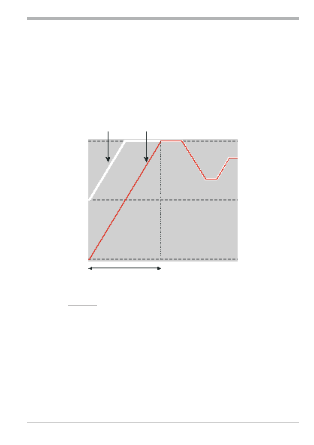
Set-point gradient / ramp
To prevent set-point step changes, parameter r set-point r r.SP can be adjusted to
a maximum rate of change. This gradientis effective in positive and negative direction..
4.3.1
With parameter r.SP set to OFF (default), the gradient is switched off and
set-point changes are realized directly.
(for parameter: see page )
4.4 Pro-8 cooling functions
Pro-8, configuration parameter CYCL
With
used for matching the cycle time of 2-point and 3-point controllers. This can be
done using the following 4 methods.
4.4.1
Standard ( CyCl= 0 )
The adjusted cycle times t1 and t2 are valid for 50% or -50% correcting variable. With very small or very high values, the effective cycle time is extended to
Set-point processing 38
(ConF/ Cntr/ CYCL) can be
Pro-8
Page 39

Configuration level
-95%
-67%
-80%
-100%
-92%
-90%
-87%
-82%
t.offt.on
0,0
1,0
2,0
3,0
4,0
5,0
6,0
5 101520253035404550556065707580859095
Controller output [%]
relative cycle duration
T/T
1
t1
2xt1
3xt1
4xt1
prevent unreasonably short on and off pulses. The shortest pulses result from ¼
x t1 or¼x t2. The characteristic curve is also called “bath tub curve”.
Parameters to be adjusted: t1 : min. cycle time 1 (heating) [s]
( PArA/ Cntr) t2 : min. cycle time 2 (cooling) [s]
4.4.2 Switching attitude
linear ( CyCl= 1 )
For heating (Y1), the standard method (see chapter 4.4.1) is used. For cooling
(Y2), a special algorithm for cooling with water is used. Generally, cooling is enabled only at an adjustable process temperature (E.H2O), because low temperatures prevent evaporation with related cooling, whereby damage to the plant is
avoided. The cooling pulse length is adjustable using parameter t.on and is fixed for all output values.
The “off” time is varied dependent of output value. Parameter t.off is used for
determining the min “off” time. For output of a shorter off pulse, this pulse is
suppressed, i.e. the max. effective cooling output value is calculated according to
formula t.on /(t.on + t.off) w 100%.
Parameters to be adjusted: E.H2O: minimum temperature for water cooling
( PArA / Cntr) t.on: pulse duration water cooling
t.off: minimum pause water cooling
4.4.3 Switching attitude
non-linear ( CyCl= 2 )
With this method, the cooling power is
normally much higher than the heating
power, i.e. the effect on the behaviour
during transition from heating to cooling may be negative. The cooling cur-
Pro-8
ve ensures that the control intervention
with0to-70%correctingvariableis
39
Cooling functions
Page 40

Configuration level
0
10
20
30
40
50
60
70
-100 -95 -90 -85 -80 -75 -70 -65 -60 -55 -50 -45 -40 -35 -30 -25 -20 -15 -10 -5
Controller output [%]
Water cooling non-linear, =1F.H2O
Water cooling non-linear, =2F.H2O
Water cooling non-linear, =0,5F.H2O
Water cooling linear
Parameter:
t.on = 0.4 sec
t.off = 0.2 sec
Effective controller output
50%
50%
t1 t2/
tp
tp
30%
70%
20%
80%
10%
90%
t1 t2/
very weak. Moreover, the correcting variable increases very quickly to max. possible cooling. Parameter F.H2O can be used for changing the characteristic curve.
The standard method (see section 4.4.1) is also used for heating. Cooling is also
enabled dependent of process temperature .
Parameters to be adjusted: E.H2O: min. temperature for water cooling
( PArA / Cntr) t.on: Pulse duration water cooling
t.off: min. pause water cooling
F.H2O: adaptation of (non-linear) characteristic
Water cooling
4.4.4
Heating and cooling with constant period ( CyCl= 3 )
The adjusted cycle times t1 and t2
are met in the overall output range .
To prevent unreasonably short pulses,
parameter tp is used for adjusting
the shortest pulse duration. With small
correcting values which require a pulse shorter than the value adjusted in
tp, this pulse is suppressed. However, the controller stores the pulse and
totalizes further pulses, until a pulse
Cooling functions
of duration tp can be output.
Parameters to be adjusted: t1 : Min. cycle time 1 (heating) [s]
( PArA/ Cntr) t2 : min. cycle time 2 (cooling) [s]
tp: min. pulse length [s]
40
Pro-8
Page 41

4.5 Configuration examples
InH.1InL.1
SP.LO SP
SP.Hi
100%
0%
Out.1Â
InP.1Ê
HYS.HHYS.L
setpoint
relay
output
process value
4.5.1 On-Off controller / Signaller (inverse)
ConF / Cntr: SP.Fn = 0 set-point /cascade controller
C.Fnc = 0 signaller with one output
C.Act = 0 inverse output action
Configuration level
(e.g. heating applications)
g
ConF / Out.1: O.Act = 0 output action Out.1 direct
Y.1 =1 control output Y1 active
PArA / Cntr: HYS.L = 0...9999 switching difference below SP
PArA / Cntr: HYS.H = 0...9999 switching difference above SP
PArA / SEtP: SP.LO = -1999...9999 lower set-point limit for Weff
SP.Hi = -1999...9999 upper set-point limit for Weff
For direct signaller action, the controller action must be changed
(ConF / Cntr / C.Act = 1 )
Pro-8
41 Configuration examples
Page 42

Configuration level
InH.1InL.1
SP.LO SP
SP.Hi
Out.1Â
InP.1Ê
100%
0%
PB1
Out.3Â
20 mA
0/4 mA
PB1
setpoint
Relayoutput
process value
4.5.2 2-point and continuous controller (inverse)
g
ConF/Cntr
ConF / Out.1:
ConF / Out.3:
PArA / Cntr:
PArA / SEtP:
SP.Fn
C.Fnc
C.Act
O.Act
Y.1
O.tYP
Out.0
Out.1
O.Src
Pb1
ti1
td1
t1
SP.LO
SP.Hi
= 0 set-point / cascade controller
= 1 2-point and continuous controller (PID)
= 0 inverse action
(e.g. heating applications)
= 0 action Out.1 direct
= 1 control output Y1 active
=1/2 Out.3 Type ( 0/4 … 20mA)
= -1999...9999 scaling analog output 0/4mA
= -1999...9999 scaling analog output 20mA
= 1 controller output y1 (continuous)
= 1...9999 proportional band 1 (heating)
in units of phys. quantity (e.g. °C)
= 0,1...9999 integral time 1 (heating) in sec.
= 0,1...9999 derivative time 1 (heating) in sec.
= 0,4...9999 min. cycle time 1 (heating)
= -1999...999 set-point limit low for Weff
= -1999...9999 set-point limit high for Weff
For direct action, the controller action must be changed
(ConF / Cntr / C.Act = 1 ).
Configuration examples 42
Pro-8
Page 43

4.5.3 3-point and continuous controller
InH.1InL.1
SP.LO SP
SP.Hi
Out.1Â
InP.1Ê
100%
0%
100%
0%
PB1
PB2
Out.2Â
Out.3Â
20 mA
0/4 mA
PB1
ConF / Cntr: SP.Fn = 0 set-point / cascade controller
C.Fnc = 3 3-point controller (2xPID)
C.Act = 0 action inverse
ConF / Out.1: O.Act = 0 action Out.1 direct
Y.1 = 1 control output Y1 active
Y.2 = 0 control output Y2 not active
ConF / Out.2: O.Act = 0 action Out.2 direct
Y.1 = 0 control output Y1 not active
Y.2 = 1 control output Y2 active
Conf / Out.3: O.typ =1 / 2 0 ... 20 mA continuous. / 4 ... 20 mA
Out.0 = 0 scaling 0 %
Out.1 = 100 scaling 100 %
O.Src = 1 controller output y1 (continuous)
PArA / Cntr: Pb1 = 0,1...9999 proportional band 1 (heating)
Pb2 = 0,1...9999 proportional band 2 (cooling)
ti1 = 1...9999 integral time 1 (heating) in sec.
ti2 = 1...9999 derivative time 2 (cooling) in sec.
td1 = 1...9999 integral time 1 (heating) in sec.
td2 = 1...9999 derivative time 2 (cooling) in sec.
t1 = 0,4...9999 min. cycle time 1 (heating)
t2 = 0,4...9999 min. cycle time 2 (cooling)
SH = 0...9999 neutr. zone in units of phys.quantity
PArA / SEtP: SP.LO = -1999...9999 set-point limit low for Weff
SP.Hi = -1999...9999 set-point limit high for Weff
Configuration level
(e.g. heating applications)
in units of phys. quantity (e.g. °C)
in units of phys. quantity (e.g. °C)
Pro-8
43 Configuration examples
Page 44

Configuration level
InH.1InL.1
SP.LO SP
SP.Hi
Out.1Â
InP.1Ê
Out.2Â
100%
0%
100%
0%
PB1
SH
4.5.4 3-point stepping controller (relay & relay)
ConF / Cntr: SP.Fn = 0 set-point / cascade controller
C.Fnc = 4 3-point stepping controller
C.Act = 0 inverse action
ConF / Out.1: O.Act = 0 action Out.1 direct
Y.1 = 1 control output Y1 active
Y.2 = 0 control output Y2 not active
ConF / Out.2: O.Act = 0 action Out.2 direct
Y.1 = 0 control output Y1 not active
Y.2 = 1 control output Y2 active
PArA / Cntr: Pb1 = 0,1...9999 proportional band 1 (heating)
ti1 = 1...9999 integral time 1 (heating) in sec.
td1 = 1...9999 derivative time 1 (heating) in sec.
t1 = 0,4...9999 min. cycle time 1 (heating)
SH = 0...9999 neutral zone in units of phy. quantity
tP = 0,1...9999 min. pulse length in sec.
tt = 3...9999 actuator travel time in sec.
PArA / SEtP: SP.LO = -1999...9999 set-point limit low for Weff
SP.Hi = -1999...9999 set-point limit high for Weff
(e.g. heating applications)
in units of phys. quantity (e.g. °C)
g
For direct action of the 3-point stepping controller, the controller output action
must be changed ( ConF / Cntr / C.Act = 1 ).
Configuration examples 44
Pro-8
Page 45

Configuration level
InH.1InL.1
SP.LO SP
SP.Hi
Out.1Â
InP.1Ê
100%
0%
PB1
Out.2Â
d.SP
SH
Out.1Â
100%
0%
PB1
4.5.5
D - Y - Off controller / 2-point controller with pre-contact
ConF / Cntr: SP.Fn = 0 set-point / cascade controller
C.Fnc = 2 D -Y-Off controller
C.Act = 0 inverse action
(e.g. heating applications)
ConF / Out.1: O.Act = 0 action Out.1 direct
Y.1 = 1 control output Y1 active
Y.2 = 0 control output Y2 not active
ConF / Out.2: O.Act = 0 action Out.2 direct
Y.1 = 0 control output Y1 not active
Y.2 = 1 control output Y2 active
PArA / Cntr: Pb1 = 0,1...9999 proportional band 1 (heating)
in units of phys. quantity (e.g. °C)
ti1 = 1...9999 integral time 1 (heating) in sec.
td1 = 1...9999 derivative time 1 (heating) in sec.
t1 = 0,4...9999 min. cycle time 1 (heating)
SH = 0...9999 switching difference
d.SP = -1999...9999 trigg. point separation suppl. cont.
D / Y / Off in units of phys. quantity
PArA / SEtP: SP.LO = -1999...9999 set-point limit low for Weff
SP.Hi = -1999...9999 set-point limit high for Weff
Pro-8
45 Configuration examples
Page 46

Configuration level
phys.
quantity
mA / V
phys. quantity
Out.1
Out.0
0/4mA
0/2V
20mA
10V
1
2
3
4
7
5
8
6
9
10
11
12
13
14
15
L
N
}
90...250VAC
24VUC
U
OUT3
INP1
4.5.6
Pro-8 with measured value output
Example: KS5_-1_2-_00_ _-_ _ _
ConF / Out.3: O.tYP = 1 Out.3 0...20mA continuous
Configuration examples 46
Out.0 = -1999...9999 scaling Out.3
Out.1 = -1999...9999 scaling Out.3
O.Src = 3 signal source for Out.3 is
= 2 Out.3 4...20mA continuous
= 3 Out.3 0...10V continuous
= 4 Out.3 2...10V continuous
for 0/4mA or 0/2V
for 20mA or 10V
the process value
Pro-8
Page 47

5 Parameter setting level
125
126
PArA
126
3Sek
PASS
Ù
()
Ù
5.1 Parameter survey
PArA Parameter setting level
Parameter setting level
È
Ì
Cntr Control and
Pb1 Pb12 SP.Lo b.Lo InL.1 Inl.2 L.1
Pb2 Pb22 SP.Hi b.Hi OuL.1 OuL.2 H.1
ti1 ti12 SP.2 SP.01 InH.1 InH.2 HYS.1
ti2 ti22 r.SP Pt.01 OuH.1 OuH.2 dEl.1
td1 td12 SP.bo SP.02 tF.1 L.2
td2 td22 t.bo Pt.02 H.2
t1 Y.St SP.03 HYS.2
t2 SP.St
SH t.St
Hys.l
Hys.H
d.SP
tP
tt
Y2
Y.Lo
Y.Hi
Y0
Ym.H
L.Ym
E.H2O
t.on
t.off
FH2o
PAr.2
self-tuning
2. set of parameters
SEtP Set-point and
process value
Pt.03
SP.04
Pt.04
SP.05
Pt.05
SP.06
Pt.06
SP.07
Pt.07
SP.08
Pt.08
SP.09
Pt.09
SP.10
Pt.10
Prog Programmer
InP.1 Input 1
InP.2 Input 2
Lim
dEl.2
L.3
H.3
HYS.3
dEl.3
HC.A
Limit value functions
End
Pro-8
Adjustment:
To access the parameter level, press the key Ù for 3 seconds and confirm using
the Ù -key subsequently. If the password function is activated, the prompt for
the PASS is displayed
The parameters can be adjusted using the ÈÌ - keys.
w
47 Parameter survey
Page 48

Parameter setting level
Press the Ù - key to change to the next parameter.
w
After the last parameter of a group, donE is displayed and followed by auto-
w
matic changing to the next group
g
g
Return to the beginning of a group, by pressing the Ù key for 3 sec.
Unless a key is pressed during 30 seconds, the controller returns to the process
value and setpoint display ( Time Out = 30 sec. )
g
Resetting the configuration parameters to default
r chapter 12.1 (page 68)
5.2 Parameters
Cntr
Name Value range Description Default
Pb1
Pb2
ti1
ti2
td1
td2
t1
t2
SH
d.SP
tP
tt
Y2
Y.Lo
Y.Hi
Y.0
Ym.H
L.Ym
E.H2O
t.on
t.oFF
F.H2O
1...9999 1
1...9999 1
1...9999
1...9999
1...9999
1...9999
0,4...9999
0,4...9999
0...9999
-1999...9999
0,1...9999
3...9999
-120...120
-120...120
-120...120
-120...120
-120...120
0...9999
-1999...9999
0,1...9999
1...9999
0,1...9999
Proportional band 1 (heating) in phys. dimensions (e.g. °C)
Proportional band 2 (cooling) in phys. dimensions (e.g. °C)
Integral action time 1 (heating) [s]
Integral action time 2 (cooling) [s]
Derivative action time 1 (heating) [s]
Derivative action time 2 (cooling) [s]
Minimal cycle time 1 (heating) [s]. The minimum impulse is 1/4 x t1
Minimal cycle time 2 (cooling) [s]. The minimum impulse is 1/4 x t2
Neutral zone or switching differential for on-off control
[phys. dimensions)
Trigger point seperation for additional contact D / Y / Off [
phys. dimensions]
Minimum impulse [s]
Motor travel time [s]
2. correcting variable
Lower output limit [%]
Upper output limit [%]
Working point for the correcting variable [%]
Limitation of the mean value Ym [%]
Max. deviation xw at the start of mean value calculation
[phys. dimensions]
Min. temperature for water cooling. Below the set temperature
no water cooling happens.
Impulse lenght for water cooling. Fixed for all values of
controller output.The pause time is varied.
Min. pause time for water cooling. The max. effective controller
output results from t.on/(t.on+t.off)·100%
Modification of the (non-linear) water cooling characteristic
(see page 39)
100
100
180
180
180
180
10
10
2
100
OFF
60
0
0
100
0
5
8
120
0,1
2
0,5
1 Valid for ConF/ othr/ dP = 0. With dP = 1 / 2 / 3 also 0,1 / 0,01 /
0,001 is possible.
Parameters 48
Pro-8
Page 49

Parameter setting level
PAr.2
Name Value range Description Default
Pb12
1...9999 1
Proportional band 1 (heating) in phys. dimensions (
100
e.g. °C), 2. parameter set
Pb22
1...9999 1
Proportional band 2 (cooling) in phys. Dimensions
100
(e.g. °C), 2. parameter set
Ti22
Ti12
Td12
Td22
0...9999
0...9999
0...9999
0...9999
Integral action time 2 (cooling) [s], 2. parameter set
Integral action time 1 (heating) [s], 2. parameter set
Derivative action time 1 (heating) [s], 2. parameter set
Derivative action time 2 (cooling) [s], 2. parameter set
180
180
180
180
SEtP
Name Value range Description Default
SP.LO
SP.Hi
SP.2
r.SP
SP.bo
t.bo
Y.St
SP.St
t.St
SP
-1999...9999
-1999...9999
-1999...9999
0...9999
-1999...9999
0...9999
-120...120
-1999...9999
0...9999
-1999...9999
Set-point limit low for Weff
Set-point limit high for Weff
Set-point 2.
Set-point gradient [/min]
Boost set-point
Boost time
Start-up setpoint (see page 56)
Set-point for start-up
Start-up hold time (see page 56)
Set-point (only visible with BlueControl!)
0
900
0
OFF
30
10
20
95
10
0
g
SP.Lo and SP.hi should be between the limits of rnGH and rnGL see
configuration r controller page 29
ProG
Name Value range Description Default
SP.01
Pt.01
SP.02
Pt.02
SP.03
Pt.03
SP.04
Pt.04
-1999...9999
0...9999
-1999...9999
0...9999
-1999...9999
0...9999
-1999...9999
0...9999
Segment end set-point 1
Segment time 1 [min]
Segment end set-point 2
Segment time 2 [min]
Segment end set-point 3
Segment time 3 [min]
Segment end set-point 4
Segment time 4 [min]
1 If SP.01 … SP.04 = OFF then following parameters are not shown
2 If segment end set-point = OFF then the segment time is not visible
100 1
10 2
100 1
10 2
200 1
10 2
200 1
10 2
Pro-8
49 Parameters
Page 50

Parameter setting level
InP.1
Name Value range Description Default
InL.1
OuL.1
InH.1
OuH.1
t.F1
-1999...9999
-1999...9999
-1999...9999
-1999...9999
-1999...9999
InP.2
Name Value range Description Default
InL.2
OuL.2
InH.2
OuH.2
-1999...9999
-1999...9999
-1999...9999
-1999...9999
Input value for the lower scaling point
Displayed value for the lower scaling point
Input value for the upper scaling point
Displayed value for the lower scaling point
Filter time constant [s]
Input value for the lower scaling point
Displayed value for the lower scaling point
Input value for the upper scaling point
Displayed value for the upper scaling point
0
0
20
20
0,5
0
0
50
50
Lim
Name Value range Description Default
L.1
H.1
HYS.1
L.2
H.2
HYS.2
L.3
H.3
HYS.3
HC.A
-1999...9999
-1999...9999
0...9999
-1999...9999
-1999...9999
0...9999
-1999...9999
-1999...9999
0...9999
-1999...9999
Lower limit 1
Upper limit 1
Hysteresis limit 1
Lower limit 2
Upper limit 2
Hysteresis limit 2
Lower limit 3
Upper limit 3
Hysteresis limit 3
Heat current limit [A]
-10
10
1
OFF
OFF
1
OFF
OFF
1
50
Parameters 50
Pro-8
Page 51

Parameter setting level
mA/V
phys.
quantity
mA / V
phys. quantity
OuH.x
OuL.x
InH.x
InL.x
5.3 Input scaling
When using current or voltage signals as input variables for InP.1 or InP.2,
scaling of input and display values at parameter setting level is required. Specification of the input value for lower and higher scaling point is in the relevant electrical unit (mA/ V).
5.3.1
g
a
5.3.2
Input Inp.1
Parameters InL.1 , OuL.1, InH.1 and OuH.1 are only visible if
ConF / InP.1 / Corr = 3 is chosen.
S.tYP Input signal InL.1 OuL.1 InH.1 OuH.1
30
(0...20mA)
40
(0...10V)
0…20mA 0 -1999...9999 20 -1999...9999
4…20mA 4 -1999...9999 20 -1999...9999
0…10V 0 -1999...9999 10 -1999...9999
2…10V 2 -1999...9999 10 -1999...9999
In addition to these settings, InL.1 and InH.1 can be adjusted in the range
(0...20mA / 0...10V) determined by selection of S.tYP .
For using the predetermined scaling with thermocouple and resistance
thermometer (Pt100), the settings of InL.1 and OuL.1 as well as of InH.1
and OuH.1 must correspond.
Input InP.2
S.tYP Input signal InL.2 OuL2 InH.2 OuH.2
30 0…20mA 0 -1999...9999 20 -1999...9999
31 0…50mA 0 -1999...9999 50 -1999...9999
In addition to these settings, InL.2 and InH.2 can be adjusted in the range
(0...20/ 50mA) determined by selection of S.tYP.
Operating manual Pro-8
51 Input scaling
Page 52

Calibration level
ConF
126
125
126
PArA
126
3Sek
PASS
Ù
()
Ì
Ù
Ì
CAl
126
r
Ì
Ù
3sec.
r
PArA
CAL
r
Ù
r
InP.1
Ù
r
InL.1
r
r
Ù
r
:
OuL.1
r
r
Ù
End
r
r
Ù
Ì
È
125
126
SP.X
run
Err
Ada
6 Calibration level
g
Measured value correction ( CAL) is visible only if
ConF / InP.1 / Corr = 1 or 2 is selected.
To access the calibration level, press the key Ù for 3 seconds and then the
w
key Ìtoselect the CAL-Menu item. Press Ù to confirm.
If the password function is activated, a prompt for the PASS is displayed.
w
In the calibration menu ( CAL), the measured value can be adapted. Two methods are available :
Offset correction ( ConF/ InP.1 / Corr =1 ):
InL.1: The input value of the scaling point is displayed.
The operator must wait, until the process is at rest.
Subsequently, the operator acknowledges the input value by pressing
key Ù.
OuL.1: The display value of the scaling point is displayed.
Before calibration, OuL.1 is equal to InL.1. The operator can correct
the display value by pressing keys ÈÌ .
Subsequently, he confirms the display value by pressing key Ù.
52
Pro-8
Page 53

Offset correction ( ConF/ InP.1 / Corr =1 ):
X
standard setting
offset correction
InL.1
OuL.1
new
display
OuL.1old
r
Ì
Ù
3sec.
r
PArA
CAL
r
Ù
r
InP.1
Ù
rr
r
Ù
Ù
InL.1
È
InL1
Ù
OuL.1
r
Ù
Ì
È
r
Ù
InH.1
È
InH.1
Ù
OuH.1
r
Ù
Ì
È
ConF
r
Ì
r
Ì
È
InP.2
Ì
È
End
125
126
SP.X
run
Err
Ada
possible on-line at the process
Calibration level
Pro-8
2-point correction ( ConF/ InP.1 / Corr = 2):
InL.1: The input value of the lower scaling point is displayed.
The operator must adjust the lower input value by means of a
process value simulator and confirm the input value by pressing key Ù.
OuL.1: The display value of the lower scaling point is displayed.
Before calibration, OuL.1 is equal to InL.1.
The operator can correct the lower display value by pressing the ÈÌ
keys. Subsequently, he confirms the display value by pressing key Ù.
53
Page 54

Calibration level
X
standard setting
2-point correction
InL.1
InH.1
OuL.1
new
OuH.1new
display
OuH.1old
OuL.1old
InH.1: The input value of the upper scaling point is displayed. .
OuH.1: The display value of the upper scaling point is displayed.
The operator must adjust the upper input value by means of the
process value simulator and confirm the input value by pressing key Ù.
Before calibration OuH.1 is equal to InH.1.
The operator can correct the upper display value by pressing keys ÈÌ
Subsequently, he confirms the display value by pressing key Ù.
g
2-point correction
( ConF/ InP.1 / Corr = 2 ):
is possible off-line with process value simulator
The parameters (OuL.1,
OuH.1) altered at CAL level
can be reset by decreasing them
below the lowest adjustment
value (OFF) using the
decrement key Ì .
54
Pro-8
Page 55

Programmer
W,X
W,X
W
SP.01
Pt.01
SP.02
Pt.02
SP.09
Pt.03
SP.10
Pt.10
t
7 Programmer
Programmer set-up:
For using the controller as a programmer, select parameter Cntr /SP.Fn = 1 in
the ConF menu. The programmer is started via one of digital inputs di1..3 or the
è key. Which input shall be used for starting the programmer is determined by
selecting parameter LOGI/P.run = 2 / 3 / 4 / 5 in the ConF menu accordingly. For assigning the program end as a digital signal to one of the relay outputs,
parameter P.End = 1 must be selected for the relevant output OUT.1...OUT.3 in
the ConF menu.
+
Programmer parameter setting:
A programmer with 4 segments is available to the user. Determine a segment duration Pt.01 .. Pt.04 (in minutes) and a segment target set-point SP.01 ..
SP.04 for each segment in the PArA menu.
Starting/stopping the programmer:
Starting the programmer is done by a digital signal at input di1..3 or the è key
selected by parameter P.run. The programmer calculates a gradient from segment end setpoint and segment time.
This gradient is always valid. Normally, the programmer starts the first segment
at process value. Because of this the effective run-time of the first segment may
differ from the at PArA level setted segment time (process value ¹ setpoint).
After program end, the controller continues controlling with the target set-point
set last. If the program is stopped during execution (signal at digital input di1..3
or the è key is taken away), the programmer returns to program start and waits
for a new start signal.
Program parameter changing while the program is running is possible.
Changing the segment time:
Changing the segment time leads to re-calculation of the required gradient. When
the segment time has already elapsed, starting with the new segment is done directly, where the set-point changes stepwisely.
Changing the segment end setpoint:
Changing the set-point leads to re-calculation of the required gradient, in order to
reach the new set-point during the segment rest time, whereby the required gradient polarity sign can change.
Pro-8
55
Page 56

Special functions
W
Set-point
Process
value
Power on
Disturbance
t
SP.St
trt.St
trt.St
SP.St-1K
SP.St-40K
1
2
3
4
5
6
7
8 Special functions
8.1 Start-up circuit
g
g
g
The start-up circuit is a special function for temperature control, e.g. hot runner
control. High-performance heating cartridges with magnesium oxyde insulation
material must be heated slowly to remove moisture and prevent destruction.
Operating principle:
1 After switching on the supply voltage, line-out to the start-up set-point SP.St
is using a maximum start-up correcting value of Y.St.
2 The start-up holding time t.St is started one K below the start-up set-point
( SP.St-1K).
3 Subsequenlyt, the process is lined out to set-point W.
4 If the process value drops by more than 40 K below the start-up set-point
(SP.St-40K) due to a disturbance, the start-up procedure is re-started ( 5, 6, 7 ).
With W < SP.St, W is used as set-point. The start-up holding time t.St is omitted.
If the gradient function (PArA/ SEtP/ r.SP ¹ OFF) was selected, start-up value
SP.St is reached with the adjusted gradient r.SP.
With the boost function (see chapter 8.2) selected, W is increased by SP.bo
during time t.bo .
The following settings can be selected:
SP.Fn = 10 set-point + start-up circuit
The start-up circuit is effective only with the internal set-point.
SP.Fn = 11 set-point, SP.E /SP.2 + start-up circuit
The start-up circuit is effective also with the external set-point SP.E and the 2nd
set-point SP.2.
Start-up circuit 56
Pro-8
Page 57

8.2 Boost function
W
Set-point
Process value
t
W+SP.bo
SP.bo
Special functions
g
The boost function causes short-time increase of the set-point, e.g. for removing
"frozen" material rests from clogged die nozzles with hot-runner control.
If configured (® ConF/ LOGI/ booS), the boost function can be started via digital input di1/2/3, with the function key on the instrument front panel or via the
interface (OPTION).
The set-point increase around boost set-point PArA /SEtP/SP.bo remains effective as long as digital signal (di1/2 3, function key, interface) remains set. The
maximum permissible cycle time (boost time-out) is determined by parameter
PArA /SEtP/t.bo.
Unless reset after elapse of boost time I t.bo, the boost function is finished by
the controller.
The boost function also works with
start-up circuit: PArA /SEtP/ SP.bo is added to W after elapse of start-up
w
holding time PArA /SEtP/ t.St.
Gradient function: set-point W is increased by PArA /SEtP/ SP.bo with
w
gradient PArA /SEtP/ r.SP.
Pro-8
57 Boost function
Page 58

Special functions
8.3 Pro-8 as Modbus master
a
This function is only selectable with BlueControl (engineering tool)!
Additions othr (only visible with BlueControl!)
Name Value range Description Default
MASt
Cycl
AdrO
AdrU
Numb
0
1
0...200
1...65535
1...65535
0...100
Controller is used as Modbus master
Slave
Master
Cycle time [ms] for the Modbus master to transmit its data to the
bus.
Target address to which the with AdrU specified data is given out on
the bus.
Modbus address of the data that Modbus master gives to the bus.
Number of data that should be transmitted by the Modbus
master.
The controller can be used as Modbus master ( ConF / othr / MASt = 1 ).
The Modbus master sends ist data to all slaves (broadcast message, controller
adress 0). It transmits its data (modbus adress AdrU) cyclic with the cycle time
Cycl to the bus. The slave controller receives the data transmitted by the masters
and allocates it to the modbus target adress AdrO.
0
60
1
1
0
If more than one data should be transmitted by the master controller ( Numb > 1)
, the modbus adress AdrU indicates the start adress of the data that should be
transmitted and AdrO indicates the first target adress where the received data
should be stored. The following data will be stored at the logically following
modbus target adresses.
With this it is possible e.g. to specify the process value of the master controller as
set-point for the slave controllers.
KS50/52-1 as Modbus master 58
Pro-8
Page 59

8.4 Linearization
In.16
In 1
.
.
.
.
.
.
Ou.1 Ou.16.....................
Linearization for input INP1
Access to table “ Lin” is always with selection of sensor type S.TYP = 18:
special thermocouple in INP1, or with selection of linearization S.Lin 1: special
linearization.
Dependent of input type, the input signals are specified in µV or in Ohm
dependent of input type.
With up to 16 segment points, non-linear signals can be simulated or linearized.
Every segment point comprises an input (In.1 … In.16) and an output (Ou.1
… Ou.16). These segment points are interconnected automatically by means of
straight lines.
The straight line between the first two segments is extended downwards and the
straight line between the two largest segments is extended upwards.
I.e. a defined output value is also provided for each input value.
When switching an In.x value to OFF, all other ones are switched off.
Condition for these configuration parameters is an ascending order.
In.1 < In.2 < ...< In.16 and Ou.1 < Ou.2 ...< Ou.16.
Special functions
Pro-8
59 Linearization
Page 60

BlueControl
The Software comprises all functions of the Expert-version.
All BluePort devices can be triggered via this software.
"Universal BlueControl "
©
9 BlueControl
BlueControl®is the projecting environment for the PMA BluePortâcontroller series. The following 3 licences with graded functionality are available:
Programeditor (Pro-4 programmer only)
The mini
version is - free of charge - at your disposal as download at WCS home-
page www.Eest-CS.com
At the end of the
installation the licence number has
to be stated or
DEMO mode must
be chosen.
At DEMO mode
the licence number
can be stated subsequently under
Help r Licence
r Change.
60 KS50/52-1
Page 61

10 Versions
Screw terminals
1
U
T + di2/3 + OUT5/6
8
90..250VAC, 2 relays (Wechsler) + mA/V/logic 4
Versions
KS5
KS 50-1 Format 48 x 96
Flat pin connector 0
90..250V AC,INP2, 3 relays
24VAC / 18..30VDC, INP2, 3 relays 1
90..250V AC, INP2, 2 relays+ mA/V/logic 2
24VAC / 18..30VDC, INP2, 2 relays+ mA/V/logic 3
No option
Modbus RTU + U
Standard configuration 0
T + di2/3 + OUT5/6
100
0
0
0
1
U69
Configuration to specification 9
No manual 0
Manual english E
cULus-certified (with screw terminals only)
Accessories delivered with the instrument
Operating manual (if selected using the ordering code)
2 fixing clamps
w
operating note in 15 languages
w
U
Pro-8
61
Page 62

Versions
Accessory equipment with ordering information
Description Order no.
Heating current transformer 50A AC 9404-407-50001
PC-adaptor for the front-panel interface (RS232) 9407-998-00001
Standard rail adapter 9407-998-00061
Operating manual
Interface description Modbus RTU
English
English
59560
9499-040-63611
BlueControl (engineering tool) Mini
Download www.
West-CS.com
BlueControl (engineering tool) Basic 9407-999-11001
BlueControl (engineering tool)
BlueControl (engineering tool)
Expert
Universal
9407-999-11011
9407-999-19011
62
Pro-8
Page 63

Technical data
11 Technical data
INPUTS
PROCESS VALUE INPUT INP1
Resolution: > 14 bits
Decimal point: 0 to 3 digits behind the decimal point
Dig. input filter: adjustable 0,000...9999 s
Scanning cycle: 100 ms
Measured value
correction:
Thermocouples
r Table 1 (page 65 )
Input resistance: ³1MW
Effect of source resistance: 1 mV/W
Cold-junction compensation
Maximal additional error: ± 0,5 K
Sensor break monitoring
Sensor current: £ 1 mA
Configurable output action
Resistance thermometer
r Table 2 (page 65 )
Connection: 2 or 3-wire
Lead resistance: max. 30 Ohm
Input circuit monitor: break and short circuit
2-point or offset correction
CONTROL INPUT DI1
Configurable as switch or push-button (the adjust
ment is possible only in common for all digital inputs)!
Connection of a potential-free contact suitable for
switching “dry” circuits.
Switched voltage: 2,5 V
Switched current: 50 mA
-
CONTROL INPUTS DI2, DI3 (OPTION)
Configurable as switch or push-button!
(the adjustment is possible only in common for all digital inputs)!
Contact-input (KS5_-1_ _ -800_ _-_ _ _)
Connection of a potential-free contact suitable for
switching “dry” circuits.
Switched voltage: 5 V
Switched current: 160 mA
Optocoupler input(KS5_-1_ _-100_ _-_ _ _)
Optocoupler input for active triggering
Nominal voltage 24 V DC external
Current sink (IEC 1131 type 1)
Logic “0” -3...5 V
Logic “1” 15...30 V
Current requirement approx.. 5 mA
Special measuring range
BlueControl (engineering tool) can be used to match
the input to sensor KTY 11-6 (characteristic is stored
in the controller).
Physical measuring range: 0...4500 Ohm
Linearization segments 16
Current and voltage signals
r Table 3 (page 65 )
Span start, end of span: anywhere within measuring range
Scaling: selectable -1999...9999
Linearization: 16 segments, adaptable with BlueControl
Decimal point: adjustable
Input circuit monitor: 12,5% below span start (2mA, 1V)
SUPPLEMENTARY INPUT INP2
Resolution: > 14 bits
Scanning cycle: 100 ms
Accuracy: < 0,5 %
Heating current measurement
via current transformer (® Accessory equipment)
Measuring range: 0...50mA AC
Scaling: adjustable -1999...0,000...9999 A
TRANSMITTER SUPPLY UT (OPTION)
Power: 22 mA / ³ 18 V
If the universal output OUT3 is used there may be no
external galvanic connection between measuring and
output circuits!
GALVANIC ISOLATION
Safety isolation
Function isolation
Process value input INP1
Mains supply Supplementary input INP2
Digital input di1
Relay outputs OUT 1,2 RS422/485 interface
Relay output OUT3 Digital inputs di2, 3
Universal output OUT3
Transmitter supply U
OUT5, OUT6
T
Current measuring range
Technical data as for INP1
Pro-8
63
Page 64

Technical data
OUTPUTS
RELAY OUTPUTS OUT1, OUT2
Contact type: KS5_-1_0-_00_ _-_ _ _
KS5_-1_1-_00_ _-_ _ _
KS5_-1_2-_00_ _-_ _ _
KS5_-1_3-_00_ _-_ _ _
2 NO contacts with common connection
KS5_-1_4-_00_ _-_ _ _
KS5_-1_5-_00_ _-_ _ _
2 potentialfree change-over contacts
Max. contact rating: 500 VA, 250 V, 2A at 48...62 Hz,
resistive load
Min. contact rating: 6V, 1 mA DC
Operating life (electr.): 800.000 duty cycles with max. rating
OUT3 USED AS RELAY OUTPUT
Contact type: potential-free changeover contact
Max.contact rating: 500 VA, 250 V, 2A at 48...62 Hz,
resistive load
Min. contact rating: 5V, 10 mA AC/DC
Operating life (electr.): 600.000 duty cycles with max.
contact rating
Note:
If the relays OUT1...OUT3 operate external contactors, these must be fitted with RC snubber circuits to
manufacturer specifications to prevent excessive
switch-off voltage peaks.
OUT3 AS UNIVERSAL OUTPUT
Galvanically isolated from the inputs.
Freely scalable resolution: 11bits
Current output
0/4...20 mA configurable.
Signal range: 0...approx.22mA
Max. load: £ 500 W
Load effect: no effect
Resolution: £ 22 mA (0,1%)
Accuracy £ 40 mA (0,2%)
Voltage output
0/2...10V configurable
Signal range: 0...11 V
Min. load: ³ 2kW
Load effect: no effect
Resolution: £ 11 mV (0,1%)
Accuracy £ 20 mV (0,2%)
OUT3 used as transmitter supply
Output power: 22 mA / ³13 V
OUTPUTS OUT5, OUT6 (OPTION)
Galvanically isolated opto-coupler outputs.
Grounded load: common positive voltage.
Output rating: 18...32 VDC; £ 70 mA
Internal voltage drop: £ 1V with I
cuit: built-in against short circuit, overload, reversed
polarity (free-wheel diode for relay loads).
max. Protective cir-
POWER SUPPLY
Dependent of order:
AC SUPPLY
Voltage: 90...260 V AC
Frequency: 48...62 Hz
Power consumption approx. 7,0 VA
UNIVERSAL SUPPLY 24 V UC
AC voltage: 20,4...26,4 V AC
Frequency: 48...62 Hz
DC voltage: 18...31 V DC class 2
Power consumption: approx.. 7,0 VA
BEHAVIOUR WITH POWER FAILURE
Configuration, parameters and adjusted set-points, control mode: Non-volatile storage in EEPROM
BLUEPORT FRONT INTERFACE
Connection of PC via PC adapter (see "Accessory
equipment"). The BlueControl software is used to
configure, set parameters and operate the controller.
BUS INTERFACE (OPTION)
Galvanically isolated
Physical: RS 422/485
Protocol: Modbus RTU
Transmission speed: 2400, 4800, 9600, 19.200 bits/sec
Address range: 1...247
Number of controllers per bus: 32
Repeaters must be used to connect a higher number of controllers.
ENVIRONMENTAL CONDITIONS
Protection modes
Front panel: IP 65 (NEMA 4X)
Housing: IP 20
Terminals: IP 00
Permissible temperatures
For specified accuracy: 0...60°C
Warm-up time: ³ 15 minutes
For operation: -20...65°C
For storage: -40...70°C
OUT3 used as logic output
Load £ 500 W 0/£20 mA
Load > 500 W 0/> 13 V
Humidity
max. 95% rel. humidity
75% yearly average, no condensation
64
Pro-8
Page 65

Technical data
Shock and vibration
Vibration test Fc (DIN 68-2-6)
Frequency: 10...150 Hz
Unit in operation: 1g or 0,075 mm
Unit not in operation: 2g or 0,15 mm
Shock test Ea (DIN IEC 68-2-27)
Shock: 15g
Duration: 11ms
Electromagnetic compatibility
Complies with EN 61 326-1
(for continuous, non-attended operation)
GENERAL
Housing
Material: Makrolon 9415 flame-retardant
Flammability class: UL 94 VO, self-extinguishing
Plug-in module, inserted from the front
Safety test
Complies with EN 61010-1 (VDE 0411-1):
Overvoltage category II, Contamination class 2
Working voltage range 300 V, Protection class II
Certifications
cULus-certification
(Type 1, indoor use)
File: E 208286
Mounting
Panel mounting with two fixing clamps at top/bottom
or right/left,
High-density mounting possible
Mounting position: uncritical
Weight: 0,27kg
Accessories delivered with the unit
Operating manual (if selected in the order code)
Fixing clamps
operating hint (12 languages)
Table 1 Thermocouple measuring ranges
Thermocouple type Range Accuracy Resolution (Ô)
L Fe-CuNi (DIN) -100...900°C -148...1652°F ß 2K 0,1 K
J Fe-CuNi -100...1200°C -148...2192°F ß 2K 0,1 K
K NiCr-Ni -100...1350°C -148...2462°F ß 2K 0,2 K
N Nicrosil/Nisil -100...1300°C -148...2372°F ß 2K 0,2 K
S PtRh-Pt 10% 0...1760°C 32...3200°F ß 2K 0,2 K
Table 2 Resistance transducer measuring ranges
Type Sens. current Range Accuracy Resolution (Ô)
Pt100
-200...100°C -140...212°F ß 1K 0,1K
Pt100 -200...850°C -140...1562°F ß 1K 0,1K
Pt1000 -200...850°C -140...392°F ß 2K 0,1K
0,2mA
KTY 11-6 -50...150°C -58...302°F ß 2K 0,05K
Table 3 Current and voltage measuring ranges
Range Input resistance Accuracy Resolution (Ô)
0-10 Volt
0-20 mA
~ 110 kW
49 W (voltage requirement ß 2,5 V)
ß 0,1 % ß 0,6 mV
ß 0,1 %
ß 1,5 mA
Pro-8
65
Page 66

Safety hints
12 Safety hints
This unit was built and tested in compliance with VDE 0411-1 / EN 61010-1 and
was delivered in safe condition.
The unit complies with European guideline 2004/108/EG (EMC) and is provided
with CE marking.
The unit was tested before delivery and has passed the tests required by the test
schedule. To maintain this condition and to ensure safe operation, the user must
follow the hints and warnings given in this operating manual.
The unit is intended exclusively for use as a measurement and control instrument
in technical installations.
a
Warning
If the unit is damaged to an extent that safe operation seems impossible, the unit
must not be taken into operation.
ELECTRICAL CONNECTIONS
The electrical wiring must conform to local standards (e.g. VDE 0100). The input
measurement and control leads must be kept separate from signal and power
supply leads.
In the installation of the controller a switch or a circuit-breaker must be used and
signified. The switch or circuit-breaker must be installed near by the controller
and the user must have easy access to the controller.
COMMISSIONING
Before instrument switch-on, check that the following information is taken into
account:
Ensure that the supply voltage corresponds to the specifications on the type
w
label.
All covers required for contact protection must be fitted.
w
If the controller is connected with other units in the same signal loop, check
w
that the equipment in the output circuit is not affected before switch-on. If necessary, suitable protective measures must be taken.
The unit may be operated only in installed condition.
w
Before and during operation, the temperature restrictions specified for con-
w
troller operation must be met.
SHUT-DOWN
For taking the unit out of operation, disconnect it from all voltage sources and
protect it against accidental operation.
If the controller is connected with other equipment in the same signal loop, check
that other equipment in the output circuit is not affected before switch-off. If necessary, suitable protective measures must be taken.
66
Pro-8
Page 67

a
Safety hints
MAINTENANCE, REPAIR AND MODIFICATION
The units do not need particular maintenance.
Warning
When opening the units, or when removing covers or components, live parts and
terminals may be exposed.
Before starting this work, the unit must be disconnected completely.
After completing this work, re-shut the unit and re-fit all covers and components.
Check if specifications on the type label must be changed and correct them, if necessary.
l
a
Caution
When opening the units, components which are sensitive to electrostatic discharge (ESD) can be exposed. The following work may be done only at workstations
with suitable ESD protection.
Modification, maintenance and repair work may be done only by trained and authorized personnel. For this purpose, the PMA service should be contacted.
The cleaning of the front of the controller should be done with a dry or a wetted
(spirit,
water) cloth.
Pro-8
67
Page 68

Safety hints
ÌÈ + Power on
1
SP.x
run
Ada
Err
torY
FAC
SP.x
run
Ada
Err
no
FAC
2
È
SP.x
run
Ada
Err
YES
FAC
SP.x
run
Ada
Err
COPY
FAC
Ù
3
4
SP.x
run
Ada
Err
8.8.8.8.
8.8.8.8.
1.
2.
12.1 Reset to default
In the event of faulty configuration, the instrument can be reset to default.
In the event of faulty configuration, the instrument can be reset to default.
1 To start resetting, the operator must hold down the increment and the
decrement key ÈÌ simultaneously when switching on the supply voltage.
g
g
g
g
2 Subsequently, press the increment key È to select YES.
3 Press Ù to confirm reset to default and to start copying (display COPY).
4 Subsequently, the instrument restarts.
In all other cases, no reset is necessary (cancellation via Timeout).
If one of the operating levels is disabled (using BlueControl®) and the Loc safety
switch is open, reset to default is not possible.
If a pass code was defined (using BlueControl®) and if the Loc safety switch is
open without an operating level being blocked, entry of the correct pass code is
prompted with text PASS after confirmation under 3. If the pass code is faulty,
resetting is not executed.
Copying COPY may take several seconds.
An individual default data set can be generated using the BlueControl®Software.
Reset to default 68
Pro-8
Page 69

Index
0-9
2-point correction............55
A
Accessories ...............62
Alarm handling ..........25-26
B
BlueControl...............61
Boost function .............58
Bus interface
Technical Data..........65
C
Calibration level (CAL)......53-55
Certifications ..............66
Configuration examples
2-point controller ......42-43
3-point stepping controller . . . 44
D - Y -Off controller.......45
Measured value output .....46
Signaller .............41
Configuration level
Configuration parameters. . 29 - 37
Parameter survey ........28
Connecting diagram ...........7
Connecting examples
di2/3, 2-wire transmitter supply . 10
INP2 current transformer .....9
OUT1/2 heating/cooling .....9
OUT3 as logic output ......10
OUT3 transmitter supply ....10
RS485 interface .........11
Control inputs di1, di2, di3
Technical data ..........64
Cooling functions
Constant period .........40
Standard .............38
Water cooling linear .......39
Water cooling non-linear ....39
Current signal measuring range ....64
D
Digital inputs di1, di2, di3
Configuration ..........34
Technical data ..........64
E
Environmental conditions .......65
Equipment ...............63
Error list ................14
Error status ...............15
F
F-key .................12
Front view ...............12
I
Input INP1
Configuration ..........30
Parameters ............51
Technical data ..........64
Input INP2
Configuration ..........31
Parameters ............51
Technical data ..........64
Input scaling ..............52
L
LED
Ada-LED............12
Err-LED ............12
ì -LED.............12
LED colours ...........
12
ò -LED.............12
run-LED............12
SP.x-LED............12
Linearization ..............60
M
Maintenance manager .......14-15
Manual tuning .............23
Modbus master .............59
Mounting ...............5-6
Pro-8
69
Page 70

O
Offset correction ............54
Optimization at the setpoint ......19
Output OUT1
Configuration ..........32
Technical data ..........65
Output OUT2
Configuration ..........32
Technical data ..........65
Output OUT3
Configuration ..........32
Technical data ..........65
Output OUT5
Configuration ..........33
Technical data ..........65
Output OUT6
Configuration ..........33
Technical data ..........65
Set-point processing ..........38
Start-up circuit .............57
T
Thermocouple measuring range ....64
V
Versions ..............62-63
Voltage signal measuring range ....64
P
Parameter setting level
Parameter survey ........48
Parameters .........49-51
Power supply ..............65
Programmer
Changing segment end setpoint . 56
Changing segment time .....56
Parameter setting ........56
Set-up ..............56
Starting/Stopping ........56
R
Reset to default .............69
Resistance thermometer measuring range
.....................64
S
Safety hints ............67-69
Safety switch...............5
Safety test................66
Self tuning
Cancellation ...........17
Causes of cancellation ......17
Self-tuning cancellation .....17
70
Pro-8
Page 71

Pro-8
71
Page 72

Subject to alterations without notice
Änderungen vorbehalten
Sous réserve de toutes modifications
5
9560
A6
 Loading...