

Page 1
Pro-16 Industrial Controller
User Guide
Pro-16
Manual Part number: 59537-1
October 2013
Page 2

© West Control Solutions
All rights reserved. No part of this document may be reproduced or published in any form or by any means without prior
written permission from the copyright owner.
A publication of West Control Solutions
P.O.Box 310229
D-34058 Kassel
Germany
9499-040-93811 / 59537-1 Page 2 of 88 Pro-16
Page 3

Table of contents
1. Mounting 6
2. Electrical connection 8
3. Operation 9
3.1 Front view 9
3.2 Operating structure 9
3.2.1 Operating Level 10
3.3 Behaviour after power-on 10
3.4 Operating level 11
3.5 Errorlist / Maintenance Manager 12
3.5.1 Error-List: 12
3.5.2 Error-Status (Self-tuning) 13
3.6 Function level 14
3.7 Self-tuning 15
3.7.1 Preparation before self-tuning 15
3.7.2 Optimization after start-up or at the set-point 16
3.7.3 Selecting the method ( ConF/ Cntr/ tunE) 16
3.7.4 Step attempt after start-up 17
3.7.5 Pulse attempt after start-up 17
3.7.6 Optimization at the set-point 17
3.7.7 Self-tuning start 20
3.7.8 Examples for self-tuning attempts 20
3.8 Help for manual tuning 22
3.9 Second PID parameter set 23
3.10 Alarm handling 24
4. Configuration level 26
4.1 Configuration overview 26
4.2 Configurations 27
4.3 Set-point processing 42
4.3.1 Set-point gradient / ramp 42
4.3.2 Cooling functions 42
4.3.3 Standard ( CyCl= 0 ) 42
4.3.4 Switching attitude linear ( CyCl=1) 43
4.3.5 Switching attitude non-linear ( CyCl= 2 ) 44
4.3.6 Heating and cooling with constant period ( CyCl=3 ) 45
9499-040-93811 / 59537-1 Page 3 of 88 Pro-16
Page 4

4.4 Configuration examples 46
4.4.1 On-Off controller / Signaller (inverse) 46
4.4.2 2-point and continuous controller (inverse) 47
4.4.3 3-point and continuous controller 48
4.4.4 3-point stepping controller (relay & relay) 49
4.4.5 - Y - Off controller / 2-point controller with pre-contact 50
4.4.6 KS 20-1 with measured value output 51
5. Parameter-Level 52
5.1 Parameter-Overview 52
5.2 Parameter 53
6. Input scaling 57
7. Calibration level 58
8. Programmer 61
8.1 Operation 61
8.1.1 Programmer display 62
8.1.2 Segment type 62
8.1.3 Bandwidth monitoring 63
8.1.4 Search run at programmer start 64
8.1.5 Behaviour after mains recovery or sensor error 64
8.2 Parameter overview 65
8.3 Parameter 66
8.4 Programmer description 68
8.4.1 General 68
8.4.2 Programmer set-up: 69
9. Special functions 71
9.1 Start-up circuit 71
9.2 Boost function 72
9.3 KS 20-1 as Modbus-Master 73
9.4 Linearization 74
9.5 Timer 75
9.5.1 Setting up the timer 75
9.5.2 Determining the timer run-time 76
9.5.3 Starting the timer 77
10. Ordering information 78
®
11. BlueControl
11.1 Configuration Port 80
9499-040-93811 / 59537-1 Page 4 of 88 Pro-16
79
Page 5

12. Technical Data 81
13. Safety notes 84
13.1 Resetting to factory setting 86
9499-040-93811 / 59537-1 Page 5 of 88 Pro-16
Page 6
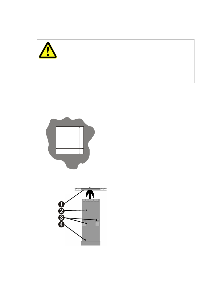
1. Mounting
Mounting
CAUTION
Make sure that the inside of the mounting plate corresponds to the instrument
operating temperature and that sufficient ventilation to prevent overheating is
provided.
Please, DON’T remove the safety device/sealing of the mounting plate, in
The mounting plate must be solid and up to 6.0 mm thick. The required cut-out is shown
below. Several instruments with the following dimensions can be installed side by side:
Instruments: (48n - 4) mm or (1.89n — 0.16) inches.
Fig. 1: Mounting dimensions
order to avoid jamming of the instrument in the mounting plate.
Mounting dimensions
The mounting depth with terminals plugged
in is 110mm.
45mm
+0,5 - 0,0
45mm
+0,5 - 0,0
1. Insert instrument into the panel cut-out.
2. Hold front bezel firmly (without pressing
on display area), and re-fit mounting
clamp. Push clamp forward, using a tool if
necessary, until gasket is compressedand
instrument held firmly in position.
Mounting plate
Housing
Latching groove
Seal
Fig. 2 : Orientation
9499-040-93811 / 59537-1 Page 6 of 88 Pro-16
Page 7

Mounting
Slip the mounting clip from
behind onto the housing until the
spring tab snaps in the latch.
Fig. 3: Mounting clip
After installing the instrument in the mounting plate, it may be removed from its housing, if
necessary (see the information on fitting and removing the optional modules).
NOTE!
The flanges of the mounting clip lock in position on both sides or on the top and
g
bottom side of the instrument housing. For optimum performance it is important
to use the latches on the sides of the instrument.
9499-040-93811 / 59537-1 Page 7 of 88 Pro-16
Page 8
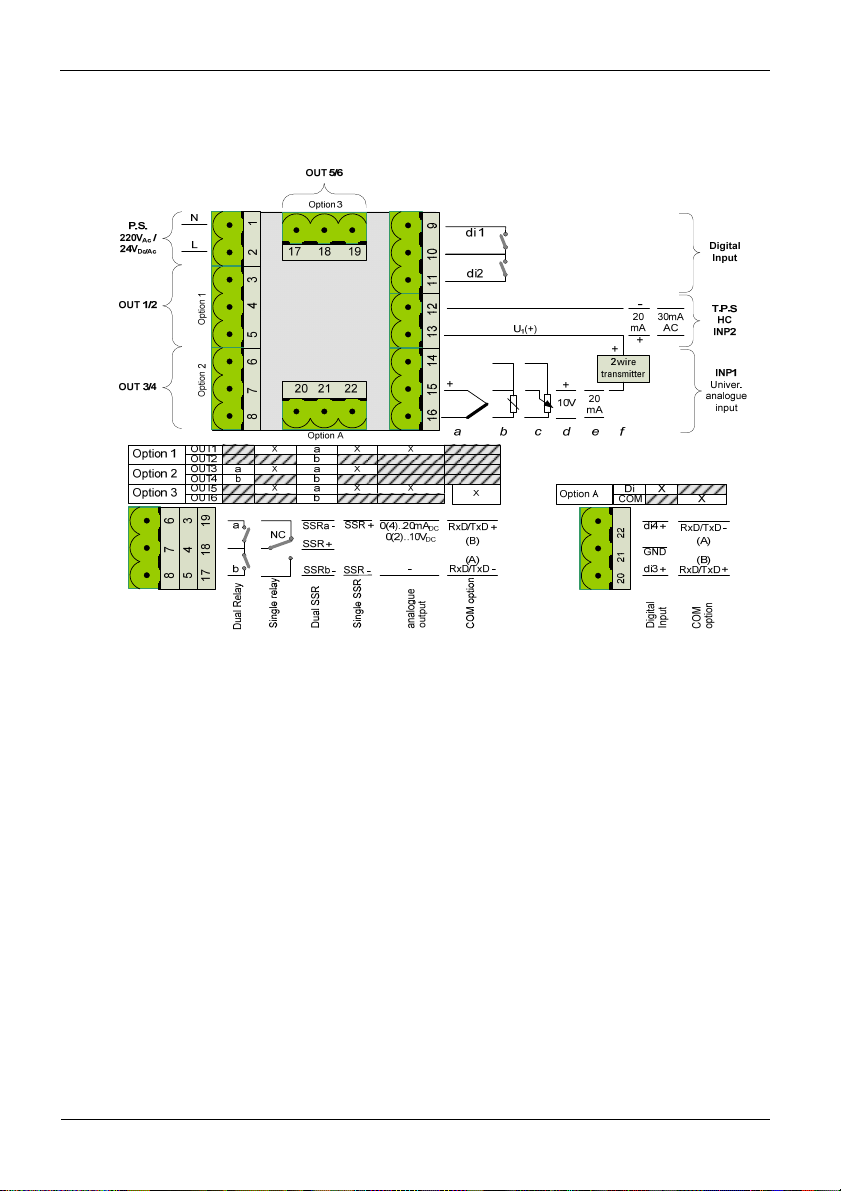
Electrical connection
2. Electrical connection
Fig. 4: Electrical connection
Connection of input INP1
Input for variable x1 (process value)
a thermocouple
b resistance thermometer (Pt100/ Pt1000/ KTY/ ...)
c potentiometer
d voltage (0/2...10V)
e current (0/4...20mA)
f Transmitter Power Supply
Connection of input INP2
current (0/4…20mA and 0…30mA AC).
Connection of inputs di1/di2/di3 and di4
Digital inputs for switching functions, e.g. SP and SP.2/SP.e or programmer
Run/Stop/Reset.
9499-040-93811 / 59537-1 Page 8 of 88 Pro-16
Page 9
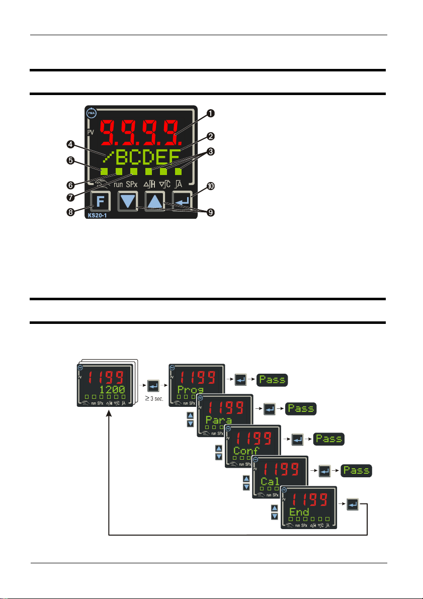
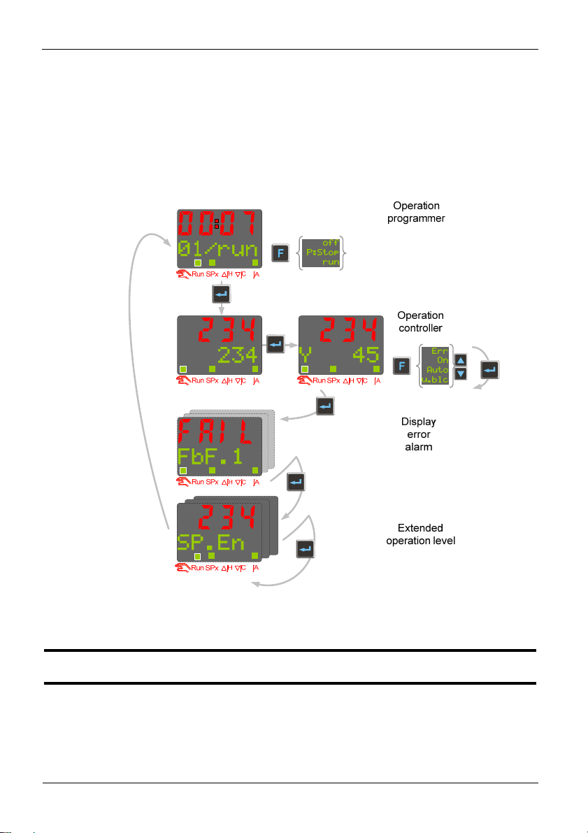
3. Operation
3.1 Front view
Fig. 5: Front view
In the upper display line, the process value is always displayed. At parameter,
configuration, calibration as well as extended operating level, the bottom display line
changes cyclically between parameter name and parameter value.
3.2 Operating structure
Operation
1 Process value display
2 Set-point, controller output, parameter
3 Status of switching outputs
4 Gradient is active
5 Manual mode
6 Timer or programmer is running
7 Set-point SP.2 oder SP.e is effective
8 Function key
9 Changing the set-point or the controller
output value
0 Acknowledges alteration of a value or
shows the next parameter/value
After supply voltage switch-on, the controller starts with the operating levels.
The controller status is as before power off.
Fig. 6: Complete operating structure (depending on configuration)
9499-040-93811 / 59537-1 Page 9 of 88 Pro-16
Page 10
The setting in the function level or in BlueControl® (engineering tool), individual layers can
be locked or made accessible by entering the password in.
Individual parameters accessible without password must be copied to the extended
operating level via BlueControl
When supplied, all levels are fully accessible,
Password PASS = OFF
3.2.1 Operating Level
Operation
®
.
See also chapter 3.4 Operating level
And chapter 3.6 Function level
3.3 Behaviour after power-on
After supply voltage switch-on, the unit starts with the operating level.
The unit is in the condition which was active before power-off.
If the controller was in manual mode before power-off, the controller starts with the last
correcting value after switching on again.
9499-040-93811 / 59537-1 Page 10 of 88 Pro-16
Page 11

3.4 Operating level
The operating level comprises two views for setpoint and controller output value. The
operating level can be enhanced with two levels
Extended operating level
Function level (see chapter 3.6)
The content of the extended operating level and the function level is determined by means
of BlueControl (engineering tool). Parameters which are used frequently or the display of
which is important can be copied to the extended operating level.
Operation
Fig. 7: Operating level and function level
9499-040-93811 / 59537-1 Page 11 of 88 Pro-16
Page 12

Operation
3.5 Errorlist / Maintenance Manager
The error list is visible only if an error entry is present. An active entry in the error list is
displayed by a red/green blinking 2nd line and status LED’s in the display.
Err-Status Signification Proceed as follows
2. line
blinks red
.. is red error
.. is green no error
All errors can be reset in the function level with Err È rSET (if configured).
3.5.1 Error-List:
Name Description
E.1
E.2
E.4
FBF.
1/2
Sht.
1/2
POL.1
HCA
SSR
existing
error
- determine the error type in the error list via the error number
- remove error
- Acknowledge the alarm in the error list by pressing key
removed
È - The alarm entry is deleted.
Cause Possible remedial action
Internal error,
E.g. defective EEPROM Contact PMA service
cannot be removed
Internal error, can
e.g. EMC trouble -shortly separate the device from
be reset
Internal error,
option modules
HW-Coding does not
match the current
recognized HW
configuration
Sensor break
INP1/2
Short circuit
INP1/2
Sensor defectiveFaulty
cabling
Sensor defectiveFaulty
cabling
INP1 polarity error Faulty cabling Reverse INP1 polarity
Heating current
alarm
- Heating current circuit
interrupted, I <
or I >
HC.A
of configuration)
- Heater band defective
Heating current
short circuit
- Current flow in
heating
HC.A
(dependent
È - or
Send- in device
mains supply
- Keep measurement and power
supply cables in separate runs
- Contact PMA service, send-in
device or check option modules
Replace INP1/2 sensor
Check INP1/2 connection
Replace INP1/2 sensor
Check INP1/2 connection
-Check heating
current circuit
- If necessary, replace
heater band
-
Check heating current circuit
- If necessary, replace solid-
9499-040-93811 / 59537-1 Page 12 of 88 Pro-16
Page 13

Loop
AdA.H
Control loop alarm - Input signal defective
Self-tuning heating
alarm (ADAH)
Ada.C
Self-tuning cooling
alarm (ADAC)
Lim.
stored limit alarm adjusted limit value
1/2/3
Inf.1
time limit value
message
Inf.2
duty cycle message
(digital ouputs)
3.5.2 Error-Status (Self-tuning)
(error status 3 - 9 only with error AdA.H / AdA.C ):
Err-Status Description Behaviour
1
Stored error Delete the entry after acknowledgment
2
Existing error Change to error status 1 after error removal
3
Faulty control action Re-configure controller (inverse i direct)
4
No response of
process variable
5
Low reversal point Let process cool down and start new adaptation attempt
6
Danger of exceeded
set-point (parameter
determined)
7
Output step change too
small
8
Set-point reserve too
small
9
Impulse tuning failed The control loop is perhaps not closed: check sensor,
Operation
circuit at controller off
state relay
- SSR defective
- Check heating or cooling circuit
or not connected
correctly
- Output not connected
correctly
See Self-tuning heating
error status
See Self-tuning cooling
error status
- Check sensor and replace
it, if necessary
- Check controller and
switching device
see Self-tuning heating error
status
See Self-tuning cooling error
status
check process
1/2/3 exceeded
adjusted number of
application-specific
operating hours reached
adjusted number of duty
application-specific
cycles reached
The control loop is perhaps not closed: check sensor,
connections and process
If necessary, increase (inverse) or reduce (direct) setpoint
Let process cool down and start new adaptation attempt
Increase set-point (invers), reduce (direkt)
connections and process
9499-040-93811 / 59537-1 Page 13 of 88 Pro-16
Page 14
3.6 Function level
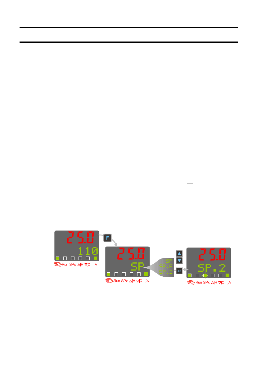
Switching functions via è key.
The function level serves for the enhanced operation of the device. You can switch
functions such as manual / automatic, Sollwert/Sp.2/Sp.E, ... via the operation level on the
controller are performed. It's content is determined by configuration ( LOGI ):
Err
Ereset
SP
SP.E
SP.2
Y
Y2
Y.ext
On
In the sequence above the list can be scrolled with the
are adjusted, with Ù or latest 2 seconds after adjustment, the value is taken over.
Pressing key è returns to normal operation.
Operation
No reset of the error list
Resetting thr error list
Internal setpoint active
External setpoint active
2nd setpoint active
Internal correcting variable
2. correcting variable
External correcting variable
Controller/Signaller and
Limit 1 are active
Off
Auto
Man
Bo.Off
Bo.On
Para.1
Para.2
Loc
rem
Controller/Signaller and
Limit 1 are switched off
Automatic operation
Manual operation
Boost function not active
Boost function aktive
First parameter set aktive
Second parameter set aktive
Local-operation adjustment via front-
panel possible
Remote-operation adjustment via
front-panel not
possible
Ù-key. With the keys ÌÈ values
Example (switching from internal setpoint to SP.2)
9499-040-93811 / 59537-1 Page 14 of 88 Pro-16
Page 15

3.7 Self-tuning
(automatic adaption of control parameters)
For determination of optimum process parameters, self-tuning is possible.
After starting by the operator, the controller makes an adaptation attempt, whereby
the process characteristics are used to calculate the parameters for fast line-out
to the set-point without overshoot.
The following parameters are optimized when self-tuning:
Parameter set 1:
Pb1
ti1
td1
t1
Pb2
ti2
td2
t2
Operation
Proportional band 1 (heating) in engineering units [e.g. °C]
Integral time 1 (heating) in [s] r only, unless set to OFF
Derivative time 1 (heating) in [s] r only, unless set to OFF
Minimum cycle time 1 (heating) in [s]. This parameter is optimized only, unless
parameter Cntr/Adt0 was configured for “no self-tuning” using BlueControl
®
Proportional band 2 (cooling) in engineering units [e.g. °C]
Integral time 2 (cooling) in [s] r only, unless set to OFF
Derivative time 2 (cooling) in [s] r only, unless set to OFF
Minimum cycle time 2 (cooling) in [s]. This parameter is optimized only, unless
parameter Cntr/Adt0 was configured for “no self-tuning”using BlueControl
®
Parameterset 2: according to Parameterset 1 (see page 23)
3.7.1 Preparation before self-tuning
o The limits of the control range must be adjusted for the controller operating range, i.e.
rnG.L and rnG.H must be adjusted to the limits within which control must take
place ConfigurationrControllerrspan start and end of control range)
ConFrCntrrrnG.L and rnG.H
o Determine which parameter set must be optimized.
- The currently effective parameter set is optimized.
r activate the corresponding parameter set (1 or 2).
o Determine which parameter must be optimized (see the list given above)
o Select the method for self-tuning (See Chapter 3.7.616)
- Step attempt after start-up
- Pulse attempt after start-up
- Optimization at the set-point
9499-040-93811 / 59537-1 Page 15 of 88 Pro-16
Page 16

Operation
3.7.2 Optimization after start-up or at the set-point
There are two methods of optimization; either after start-up or at the set-point. As control
parameters are always optimal only for a limited process range, various methods can be
selected dependent of requirements. If the process behavior is very different after start-up
and directly at the set-point, parameter sets 1 and 2 can be optimized using different
methods.
page 23).
Switch-over between parameter sets dependent of process status is possible (see
Optimization after start-up: (see page 17)
Optimization after start-up requires a certain separation between process value and setpoint. This separation enables the controller to determine the control parameters by
evaluation of the process whilst progressing to the set-point. This method optimizes the
control loop from the start conditions to the set-point, whereby a wide control range is
covered. We recommend selecting optimization method “Step attempt after start-up” with
tunE = 0 first. Unless this attempt is completed successfully, we then recommend a
“Pulse attempt after start-up”.
Optimization at the set-point: (see page 17)
For optimizing at the set-point, the controller outputs a disturbance variable to the process.
This is done by briefly changing the output variable. The process value changed by this
pulse is evaluated. The detected process parameters are converted into control parameters
and saved in the controller. This procedure optimizes the control loop directly at the setpoint. The advantage is in the small control deviation during optimization.
3.7.3 Selecting the method ( ConF/ Cntr/ tunE)
Selection criteria for the optimization method:
tunE Step attempt
after start-up
= 0 sufficient set-point
reserve is provided
= 1 sufficient set-point
= 2 Only step attempt after
Pulse attempt
after start-up
Optimization at
the set-point
sufficient set-point
reserve is not provided
sufficient set-point
reserve is provided
reserve is not provided
start-up required
Sufficient set-point reserve:
inverse controller: process value is (10% of rnGH - rnGL) below the set-point
direct controller: process value is (10% of rnGH - rnGL) above the set-point
9499-040-93811 / 59537-1 Page 16 of 88 Pro-16
Page 17

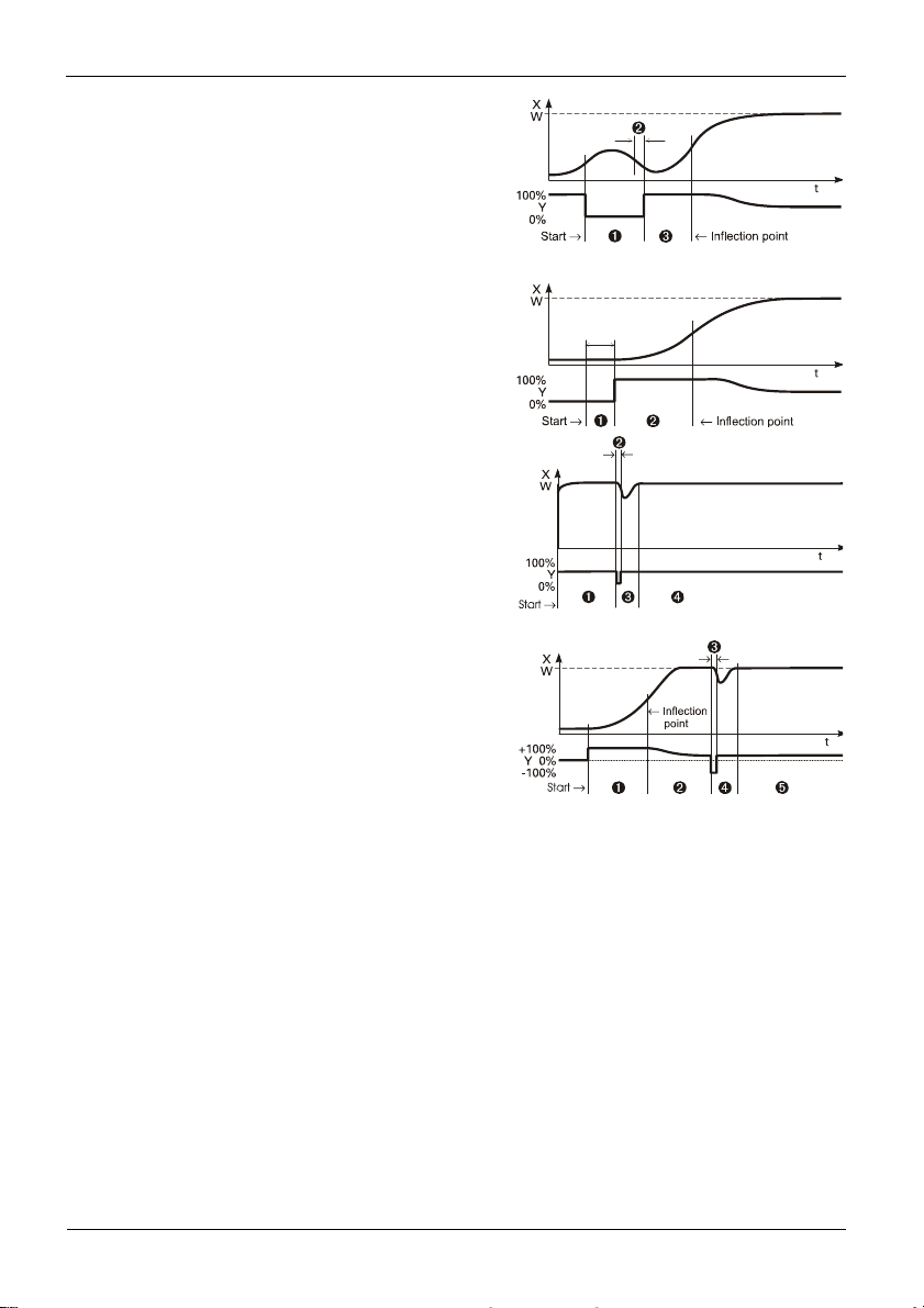
3.7.4 Step attempt after start-up
Condition: - tunE = 0 and sufficient set-point reserve provided
or - tunE = 2
The controller outputs 0% correcting variable or Y.Lo and waits, until the process is at
rest (see start-conditions on page 15).
Subsequently, a correcting variable step change to 100% or Y.Hi is output.
The controller attempts to calculate the optimum control parameters from the process
response. If this is done successfully, the optimized parameters are taken over and used for
line-out to the set-point.
With a 3-point controller, this is followed by “cooling”.
After completing the 1st step as described, a correcting variable of -100% or Y.Lo
(100% cooling energy) is output from the set-point. After successful determination of the
“cooling parameters”, the controller will proceed to the setpoint using the optimized
parameters.
3.7.5 Pulse attempt after start-up
Condition: - tunE = 1 and sufficient set-point reserve provided.
The controller outputs 0% correcting variable or Y.Lo and waits, until the process is at
rest (see start conditions page 15)
Subsequently, a short pulse of 100% or Y.Hi is output (Y=100%) and reset.
The controller attempts to determine the optimum control parameters from the process
response. If this is completed successfully, these optimized parameters are taken over and
used for stabilized to the set-point.
With a 3-point controller, this is followed by “cooling”.
After completing the 1st step as described and stabilized to the set-point, correcting
variable "heating" remains unchanged and a cooling pulse (100% cooling energy) is output
additionally. After successful determination of the “cooling parameters”, the optimized
parameters are used for stabilized to the set-point.
Operation
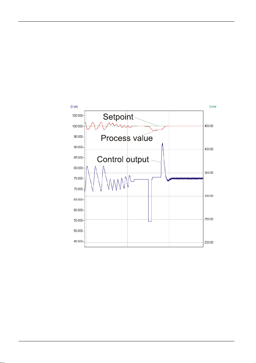
3.7.6 Optimization at the set-point
Conditions:
A sufficient set-point reserve is not provided at self-tuning start (see page 16).
tunE is 0 or 1
With Strt = 1 configured and detection of a process value oscillation by more
than ± 0,5% of (rnG.H - rnG.L) by the controller, the control parameters
are preset for process stabilization and the controller realizes an optimization at the
set-point (see figure “Optimization at the set-point”).
when the step attempt after power-on has failed
9499-040-93811 / 59537-1 Page 17 of 88 Pro-16
Page 18
Operation
with active gradient function ( PArA/ SETP/ r.SP OFF), the set-point
gradient is started from the process value and there isn't a sufficient set-point
reserve.
Optimization-at-the-set-point procedure:
The controller uses its instantaneous parameters for control to the set-point. In stable
condition, the controller makes a pulse attempt. This pulse reduces the correcting variable
by max. 20% 1, to generate a slight process value undershoot. The changing process is
analyzed and the parameters thus calculated are recorded in the controller. The optimized
parameters are used for stabilized to the set-point.
Optimization at the set-point
With a 3-point controller, optimization for the “heating“ or “cooling” parameters occurs
dependent of the instantaneous condition.
While the controller is in the "heating-phase" the heating-parameters are determined. If the
controller is in the "cooling-phase" the cooling-parameters are determined.
1 If the correcting variable is too low for reduction in stable condition
it is increased by max. 20%.
9499-040-93811 / 59537-1 Page 18 of 88 Pro-16
Page 19
t
Operation
Optimization at the set-point for 3-point stepping controller
As position feedback is not provided, the controller calculates the actuator position
internally by adjusting an integrator with the adjusted actuator travel time.
For this reason, precise entry of the actuator travel time (tt), as time between stops is
highly important.
Due to position simulation, the controller knows whether an increased or reduced pulse
must be output. After supply voltage switch-on, position simulation is at 50%. When the
motor actuator was varied by the adjusted travel time in one go, internal calculation
occurs, i.e. the position corresponds to the simulation:
Simulation real position
Internal calculation
t
Internal calculation always occurs, when the actuator was varied by travel time
tt in one go , independent of manual or automatic mode. When interrupting the variation,
internal calculation is cancelled. Unless internal calculation occurred already after selftuning start, it will occur automatically by closing the actuator once.
Unless the positioning limits were reached within 10 hours, a significant deviation between
simulation and actual position may have occurred. In this case, the controller would realize
minor internal calculation, i.e. the actuator would be closed by 20 %, and re-opened by 20
% subsequently. As a result, the controller knows that there is a 20% reserve for the
attempt.
9499-040-93811 / 59537-1 Page 19 of 88 Pro-16
Page 20

3.7.7 Self-tuning start
The operator can start self-tuning at any time. For this, keys
simultaneously. With blinking in the second row the active adaptation is displayed
Ad:PIR. The controller outputs 0%, waits until the process is at rest and starts selftuning: Ad:Stp
The self-tuning attempt is started when the following prerequisite is met:
The difference between process value i set-point must be 10% of the set-point
range ( SP.Hi - SP.LO) (with inverse action: process value smaller than setpoint, with direct action: process value higher than set-point).
After successful self-tuning, the AdA-LED is off and the controller continues operating with
the new control parameters.
Self-tuning cancellation by the operator:
Self-tuning can always be cancelled by the operator. For this, press
simultaneously. The controller continues operating with the old parameters in automatic
mode in the first case and in manual mode in the second case.
Self-tuning cancellation by the controller:
An error detected during self-tuning means that the technical conditions prevent successful
self-tuning.
In this case, self-tuning was cancelled by the controller. The controller switches off its
outputs (controller output 0%), to avoid exceeding the setpoint.
The user has two possibilities to acknowledge a failed adaptation:
1. Press keys
The controller continues controlling using the old parameters in automatic mode. The
self-tuning error must be acknowledged in the error list.
2. Press key
Display of error list at extended operating level. After acknowledgement of the error
message, the controller continues control in automatic mode using the old
parameters.
Cancellation causes: r page 13: "Error status"
Operation
Ù and È simultaneously:
Ù :
Ù and È must be pressed
Ù and È key
Acknowledgement of failed self-tuning
When pressing the
Ù key, the controller switches over to correcting variable display
(Y ....). After pressing the key again, the controller goes to the error list of the extended
operating level. The error message can be acknowledged by switching the message to 0
using the Ì - or the È key.
After acknowledging the error message, the controller continues operating in the automatic
mode, using the parameters valid prior to self-tuning start.
3.7.8 Examples for self-tuning attempts
(controller inverse, heating or heating/cooling)
9499-040-93811 / 59537-1 Page 20 of 88 Pro-16
Page 21
Start: heating power switched on
Heating power Y is switched off (1). When the
change of process value X was constant during one
minute (2), the power is switched on (3).
At the reversal point, the self-tuning attempt is
finished and the new parameter are used for
controlling to set-point W.
Start: heating power switched off
The controller waits 1,5 minutes (1). Heating
power Y is switched on (2). At the reversal point,
the self-tuning attempt is finished and control to the
set-point is using the new parameters.
Self-tuning at the set-point a
The process is controlled to the set-point. With the
control deviation constant during a defined time
(1), the controller outputs a reduced correcting
variable pulse (max. 20%) (2). After determination
of the control parameters using the process
characteristic (3), control is started using the new
parameters (4).
Three-point controller a
The parameter for heating and cooling are
determined in two attempts. The heating power is
switched on (1). Heating parameters Pb1,
ti1, td1 and t1 are determined at the
reversal point. The process is controlled to the setpoint (2). With constant control deviation, the
controller provides a cooling correcting variable
pulse (3). After determining its cooling parameters
Pb2, ti2, td2 and t2 (4) from the process
characteristics , control operation is started using
the new parameters (5).
Operation
9499-040-93811 / 59537-1 Page 21 of 88 Pro-16
Page 22
During phase 3, heating and cooling are done simultaneously!
3-point-stepping controller
After the start (1) the controller closes the
actuator (2 Out.2). When the difference
between process value and set-point is big
enough (3), the changing of the process value
is monitored for 1 min. (4). Afterwards the
actuator is opened (5 Out.1). If the reversal
point is reached (6) or there are made enough
measurements, the parameters are detected
and are adopted.
3.8 Help for manual tuning
The optimization aid should be used with units on which the control parameters shall be
set without self-tuning.
For this, the response of process variable x after a step change of correcting variable y can
be used. Frequently, plotting the complete response curve (0 to 100%) is not possible,
because the process must be kept within defined limits.
100%
X
max
0%
Values T
be used to determine the maximum rate of increase v
y
Y
h
x
and x
g
Tu
(step change from 0 to 100 %) or t and x (partial step response) can
max
Tg
{X
{t
Operation
max
W
X
1 min
1
2
5
6
4
3
.
t
t
y = correcting variable
Yh = control range
Tu = delay time (s)
Tg = recovery time (s)
X
= maximum process value
max
t
V
max
X
=
Tg
max. rate of increase of process value
x
Δmax
=
= max.
t
Δ
The control parameters can be determined from the
values calculated for delay time Tu , maximum rate of
t
increase v
according to the formulas given below. Increase Pb, if
, control range Xh and characteristic K
max
stabilized to the set-point oscillates.
9499-040-93811 / 59537-1 Page 22 of 88 Pro-16
Page 23
Pb1
td1
ti1
OFF
OFF
OFF
Parameter adjustment effects
Parameter Control Stabilized of disturbances Start-up behaviour
higher increased damping slower stabilized slower reduction of duty cycle
lower reduced damping faster stabilized faster reduction of duty cycle
higher reduced damping faster response to disturbances faster reduction of duty cycle
lower increased damping slower response to disturbances slower reduction of duty cycle
higher increased damping slower stabilized slower reduction of duty cycle
lower reduced damping faster stabilized faster reduction of duty cycle
Formulas
K = Vmax * Tu
With 2-point and 3-point
controllers, the cycle time must
be adjusted to
t1 / t2 ß 0,25 * Tu
3.9 Second PID parameter set
Operation
controller behaviour
PID 1,7 * K 2 * Tu 2 * Tu
PD 0,5 * K Tu OFF
PI 2,6 * K
P K
3-point-stepping 1,7 * K Tu 2 * Tu
Pb [phys. units] td [s] ti [s]
6 * Tu
The process characteristic is frequently affected by various factors such as process value,
correcting variable and material differences.
To comply with these requirements, the controller can be switched over between two
parameter sets. Parameter sets PArA and PAr.2 are provided for heating and cooling.
Dependent of configuration, switch-over to the second parameter set
(ConF/LOG/Pid.2) is via key
or interface (OPTION).
Self-tuning is always done using the active parameter set, i.e. the second
g
parameter set must be active for optimizing.
9499-040-93811 / 59537-1 Page 23 of 88 Pro-16
è , one of digital inputs di1…di4
Page 24
O
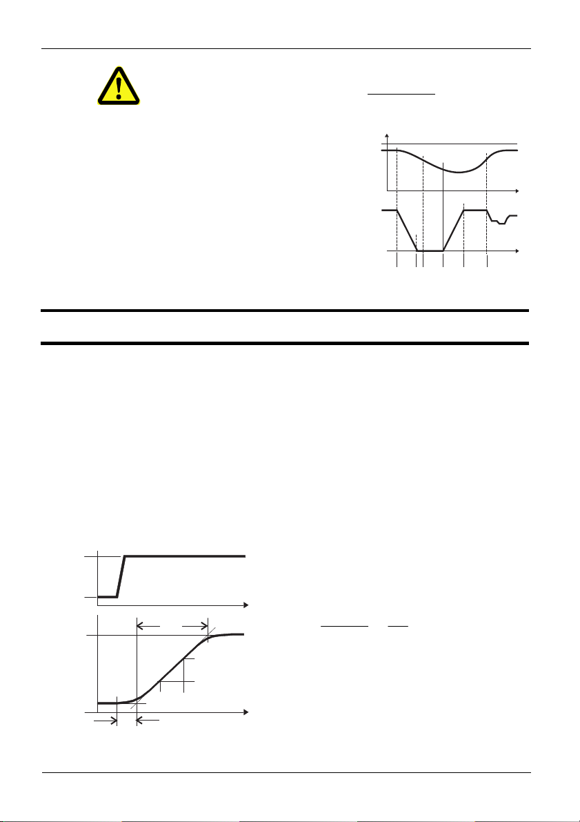
3.10 Alarm handling
Max. three alarms can be configured and assigned to the individual outputs. Generally,
outputs OuT.1... OuT.6 can be used each for alarm signalling. If more than one
signal is linked to one output the signals are OR linked. Each of the 3 limit values Lim.1
… Lim.3 has 2 trigger points H.x (Max) and L.x (Min), which can be switched off
individually (parameter = “OFF”). Switching difference HYS.x of each limit value is
adjustable.
Ü Operaing principle absolute alarm
L.1 = OFF
Operation
¡ Operating principle relative alarm
L.1 =
FF
H.1 = OFF
H.1 = OFF
Normally open: See examples (ConF / Out.x / O.Act = 0)
Normally closed: The output relay action is inverted (ConF/ Out.x / O.Act = 1)
The alarm LED always shows the threshold violation on (out of
limits, switching point). If several alarms are used can be
checked at the operating level, which alarm is active
(
Ù …r Lim.1 Ù … Lim.3)
The variable to be monitored can be selected separately per configuration for each
g
alarm.
9499-040-93811 / 59537-1 Page 24 of 88 Pro-16
Page 25

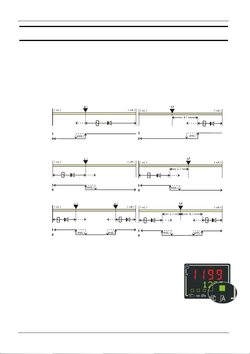
The following variables are available ( ConF / Lim / Src .x ):
Variable (Src .x) Remark Alarm type
Process value Absolute
Control deviation xw Process value - effective set-point. The effective
Control deviation xw +
suppression after startup or set-point change
with time limit
Effective set-point
Weff
Correcting variable y y = controller output signal Absolute
Deviation from SP
internal
Control deviation xw +
suppression after startup or set-point change
without time limit
g
Function (Fnc.x) Remark
Switched off No limit value monitoring.
Measured value Process value monitoring. When exceeding the limit, an alarm is
Measured value + latch Process value monitoring + latching of the alarm condition. When
During alarm configuration, the following functions can be selected
( ConF / Lim / Fnc.x ):
Operation
Relative
set-point Weff is used. E.g with a ramp, this is the
changing set-point rather than the target set-point.
The alarm output is suppressed after switch-on or
after a set-point change, until the process value is
within the limits for the first time. At the latest
after elapse of time 10 x ti1 the alarm is
activated (ti1 = integral time 1; parameter r
Cntr). If ti1 is switched off (ti1 = OFF),
this is considered as Î , i.e. the alarm is not
activated before the process value was within the
limits once.
The effective set-point Weff for control. Absolute
Process value - internal set-point. The internal setpoint is used. E.g. with a ramp, this is the target
set-point instead of the varying effective set-point
Weff.
After switch-on or after a set-point change, the
alarm output is suppressed , until the process value
is within the limits for the first time.
generated.The alarm is reset automatically, when the process
value is "within the limits" (including hysteresis) again.
exceeding the limit value, an alarm is output. A latched alarm
persists, until it is reset manually.
Relative
Relative
Relative
9499-040-93811 / 59537-1 Page 25 of 88 Pro-16
Page 26
4. Configuration level
4.1 Configuration overview
Configuration level
ConF Configuration level
È
Ì
Cntr Control and self-tuning
ProG Programmer
InP.1 Input 1
InP.2 Input 2
Lim Limit value functions
SP.Fn t.bAS StYP I.Fnc Fnc.1 O.tYP O.Act
b.ti S.Lin StYP Src.1 O.Act Y.1 SP.2 Addr
C.Fnc Corr Fnc.2 Y.1 Y.2 SP.E PrtY
mAn Src.2 Y.2 Lim.1
C.Act Fnc.3 Lim.1 Lim.2
FAIL Src.3 Lim.2 Lim.3
Ù
rnG.L HC.AL Lim.3 LP.AL
rnG.H LP.AL LP.AL HC.AL
Sp2C HC.AL HC.SC boos
CyCL HC.SC TimE Pid.2
tunE TimE t.End
Strt t.End P.End
FAi.2 PrG.1
PrG2 PrG3
PrG4 CALL
OuT.0
out1 Output 1
P.End FAi.1
FAi.1 FAi.2
PrG.1 PrG2
PrG3 PrG4
CALL
Out.1
O.Src
ut3 Output 3
Out2 Output 2
O
See output 2
Out4 Output 4
out5 Output 5
See output 2
See output 1
out6 Output 6
Logi Digital inpu ts
L_r bAud
Y.2 dELY
y.E Unit
See output 2
mAn dP
C.oFF Led
Err.r C.dEl
P.run
P.oFF
di.Fn
othr Display, operation,
interface
End
quit
9499-040-93811 / 59537-1 Page 26 of 88 Pro-16
Page 27
LOGI
E
SP.E
2
Configuration
level
Adjustment:
To access the configuration level, press the key
Ì to select the ConF-Menu item. Press Ù to confirm.
Ù for 3 seconds and then the key
If the password function is activated, a prompt for PASS is displayed.
The configuration values can be adjusted using the ÌÈ keys. Press the
Ù key to save the value. The next configuration value is shown.
After the last configuration value of a group, donE is displayed, followed by
automatic changing to the next group
g Return to the beginning of a group, by pressing the Ù key for 3 sec
g Press menu item quit to close/cancel configuration
4.2 Configurations
Cntr
Name Value range Description Default
SP.Fn
b.ti 0…9999 Timer tolerance band 5
C.Fnc
Basic configuration of setpoint processing 0
0 set-point controller can be switched over to external set-point
(->
/ SP.
1 program controller
2 timer, mode 1 (bandwidth-controlled, switched off at the end)
3 timer, mode 2 (bandwidth-controlled, set-point remains active
at the end)
4 timer, mode 3 (switched off at the end)
5 timer, mode 4 (set-point remains active at the end)
6 timer, mode 5 (switch-on delay)
7 timer, mode 6 (set-point switch-over)
10 controller with start-up circuit (see page 71)
11
Fixpoint /
Control behaviour (algorithm) 1
0 on/off controller or signaller with one output
1 PID controller (2-point and continuous)
)
/ SP.
controller with start-up circuit (see page 71)
9499-040-93811 / 59537-1 Page 27 of 88 Pro-16
Page 28

Configuration level
LOGI
L.Y
L.Y
2 / Y / Off, or 2-point controller with partial/full load switch-
over
3 2 x PID (3-point and continuous)
4 3-point stepping controller
mAn
C.Act
Manual operation permitted 0
0 no
1 yes (see also
/ mAn)
Method of controller operation 0
0 inverse, e.g. heatingWith decreasing process value, the
correcting variable is increased, with increasing process
value, the correcting variable is reduced.
1 direct, e.g. coolingWith increasing process value, the
correcting variable is increased, with decreasing process
value, the correcting variable is decreased
FAIL Behaviour at sensor break 1
0 controller outputs switched off
1 y = Y2
2 y = mean output. In the event of a failure of the input signal,
the mean value of the correcting variable output last is
kept.The maximum permissible output can be adjusted with
parameter
Ym.H. To prevent determination of inadmissible
values, mean value formation is only if the control deviation is
lower than parameter
m.
3 y = mean output; manual adjustment is possible.In the event of
a failure of the input signal, the mean value of the correcting
variable output last is kept.The maximum permissible output
can be adjusted using parameter Ym.H . The mean output is
measured at intervals of 1 min., when the control deviation is
smaller than parameter
m.
rnG.L -1999...9999 X0 (lower limit of control range ) indicates the smallest value
to be expected as process value.
rnG.H -1999...9999 X100 (high limit range of control) indicates the highest value
to be expected as process value.
SP2C With active SP.2 no cooling controlling is provided 0
0 standard (cooling permissible with all set-points)
1 no cooling provided with active SP.2
CYCL Characteristic for 2-point- and 3-point-controllers 0
0 Standard (see page 42)
1 water cooling linear (see page 43)
2 water cooling non-linear (see page 44)
3 with constant cycle (see page 45)
-100
1200
9499-040-93811 / 59537-1 Page 28 of 88 Pro-16
Page 29

Configuration
level
tunE Auto-tuning at start-up 0
0 At start-up with step function
1 At start-up with impulse function. Setting for fast controlled
systems (e.g. hot runner control)
2 Always step attempt during start-up
Strt Start of auto-tuning 0
0 no automatic start (manual start via front interface)
1 Manual or automatic start of auto-tuning at power on or when
oscillating is detected
Adt0 Optimization of T1, T2 (only visible with BlueControl!) 0
0 Automatic optimization
1 No optimization
Prog
Name Value range Description Default
t.bAS
Time base 0
0 hours:minutes
1 minutes:seconds
InP.1
Name Value range Description Default
S.tYP
Sensor type selection 1
0 thermocouple type L (-100...900°C) , Fe-CuNi DIN
1 thermocouple type J (-100...1200°C) , Fe-CuNi
2 thermocouple type K (-100...1350°C), NiCr-Ni
3 thermocouple type N (-100...1300°C), Nicrosil-Nisil
4 thermocouple type S (0...1760°C), PtRh-Pt10%
5 thermocouple type R (0...1760°C), PtRh-Pt13%
6 thermocouple type T (-200…400°C), Cu-NiCu
7 thermocouple type C (0...2315°C), W5%Re-W26%Re
8 thermocouple type D (0...2315°C), W3%Re-W25%Re
9 thermocouple type E (-100...1000°C), NiCr-CuNi
10 thermocouple type B (0/100...1820°C), PtRh-Pt6%
18 special thermocouple
20 Pt100 (-200.0 ... 100,0 °C)
( -200,0 ... 150,0°C with reduced lead resistance: measuring
resistance + lead resistance 160[)
21 Pt100 (-200.0 ... 850.0 °C)
22 Pt1000 (-200.0 ... 850.0 °C)
9499-040-93811 / 59537-1 Page 29 of 88 Pro-16
Page 30
Configuration level
23 special 0...4500 Ohm (pre-defined as KTY11-6)
30
0...20mA / 4...20mA Scaling is required (see chp. page 57)
40 0...10V / 2...10V Scaling is required (see chp. page 57)
S.Lin
Linearization (only at S.tYP = 23 (KTY 11-6), 30 (0..20mA)
0
and 40 (0..10V) adjustable) (see page 74)
0 Without linearization
1 Linearization to specification. Creation of linearization table
with BlueControl (engineering tool) possible. The
characteristic for KTY 11-6 temperature sensors is preset.
Corr Measured value correction / scaling 0
0 Without scaling
1 Offset correction (at CAL level) (see page 58)
2 2-point correction (at CAL level 58)
3 Scaling (at PArA level) (see page 57)
fAI1 Forcing INP1 (only visible with BlueControl®!) 0
0 No forcing
1 Forcing via serial interface
InP.2
Name Value range Description Default
I.Fnc
S.tYP
fAI2 Forcing INP2 (only visible with BlueControl®!) 0
9499-040-93811 / 59537-1 Page 30 of 88 Pro-16
Function selection of INP2 1
0 no function (subsequent input data are skipped)
1 heating current input
2 external set-point (SP.E)
5
default correcting variable Y.E (switchover -> LOGI
/ Y.E
)
Sensor type selection 31
30
0...20mA / 4...20mA Scaling is required (see chp. page 57)
31 0...50mA AC Scaling is required. (see chp. page 57)
0 No forcing
1 Forcing via serial interface
Page 31
LOGI
Configuration
level
Lim
Name Value range Description Default
Fnc.1
Fnc.2
Fnc.3
Function of limit 1/2/3 1
0 switched off
1 measured value monitoring
2 Measured value monitoring + alarm status storage. A stored
limit value can be reset via error list, è-key, or a digital
/ Err.r)
Src.1
Src.2
Src.3
input ( ->
Source of Limit 1/2/3 1
0 process value
1 control deviation xw (process value - set-point)
2 control deviation xw (with suppression after start-up and
set-point change)
6 effective setpoint Weff
7 correcting variable y (controller output)
8 control variable deviation xw (actual value - internal
setpoint) = deviation alarm to internal setpoint
11 Control deviation Xw (=relative alarm) with suppression
after start-up or set-point change without time limit.
HC.AL
Alarm heat current function (INP2) 0
0 switched off
1 Overload short circuit monitoring
2 Break and short circuit monitoring
LP.AL
Monitoring of control loop interruption for heating 0
0 switched off / inactive
1
LOOP alarm active. A loop alarm is output, unless the process value
reacts accordingly after elapse of 2 xti1 with Y=100%.
With ti1=0 , the LOOP alarm is inactive!
Hour OFF..999999 Operating hours (only visible with BlueControl®!) OFF
Swit OFF..999999 Output switching cycles (only visible with BlueControl®!) OFF
Out.1
Name Value range Description Default
O.tYP
Signal type selection OUT1 0
0 relay / logic (only visible with current/logic voltage)
1 0 ... 20 mA continuous (only visible with current/logic/voltage)
2 4 ... 20 mA continuous (only visible with current/logic/voltage)
3 0...10 V continuous (only visible with current/logic/voltage)
9499-040-93811 / 59537-1 Page 31 of 88 Pro-16
Page 32

Configuration level
O.TYP
O.TYP
O.TYP
O.TYP
O.TYP
O.TYP
O.TYP
O.TYP
O.TYP
O.TYP
O.TYP
O.TYP
4 2...10 V continuous (only visible with current/logic/voltage)
5 transmitter supply (only visible without OPTION)
O.Act
Method of operation of output OUT (only visible when
=0)
0 direct / normally open
1 inverse / normally closed
Y.1
Y.2
Controller output Y1/Y2 (only visible when
0 not active
1 active
Lim.1
Lim.2
Lim.3
LP.AL
Limit 1/2/3 signal (only visible when
0 not active
1 active
Interruption alarm signal (LOOP) (only visible when
0 not active
1 active
HC.AL
Heat current alarm signal (only visible when
0 not active
1 active
HC.SC
Solid state relay (SSR) short circuit signal (only visible when
=0)
0 not active
1 active
timE Timer active (only visible when
0 not active
1 Active
t.End
Timer End (only visible when
0 not active
1 active
P.End
Programmer end signal (only visible when
0 not active
1 active
FAi.1
FAi.2
INP1/ INP2 error signal (only visible when
0 not active
1 active
PrG.1
PrG.2
PrG.3
PrG.4
Program track 1 to 4 (only visible when
0 not active
1 active
CALL Operator call (only visible when
0
=0) 1
=0) 0
=0) 0
=0) 0
0
=0) 0
=0) 0
=0) 0
=0) 0
=0) 0
=0) 0
9499-040-93811 / 59537-1 Page 32 of 88 Pro-16
Page 33

O.TYP
O.TYP
O.TYP
Configuration
level
0 not active
1 active
Out.0 -1999...9999 Scaling of the analog output for 0% (0/4mA or 0/2V, only
visible when
=1..5)
Out.1 -1999...9999 Scaling of the analog output for 100% (20mA or 10V, only
O.Src
visible when
Signal source of the analog output OUT3 (only visible when
=1..5)
=1..5)
0 not used
1 controller output y1 (continuous)
2 controller output y2 (continuous)
3 process value
4 effective set-point Weff
5 control deviation xw (process value - set-point)
6 No function
fOut Forcing OUT1 (only visible with BlueControl!) 0
0 No forcing
1 Forcing via serial interface
Out.3
Out.5
Configuration parameters Out.2 as Out.1 except for: Default Y.1 = 0, Y.2 = 1
Configuration parameters Out.5 as Out.1 except for default values:
All values are 0!
Out.2 / 4 / 6
Name Value range Description Default
O.Act
Y.1
Y.2
Lim.1
Lim.2
Lim.3
LP.AL
HC.AL
Method of operation of output
0 direct / normally open
1 inverse / normally closed
Controller output Y1/Y2 0
0 not active
1 active
Limit 1/2/3 signal 1
0 not active
1 active
Interruption alarm signal (LOOP) 0
0 not active
1 active
Heating current alarm signal 0
0
100
1
1
9499-040-93811 / 59537-1 Page 33 of 88 Pro-16
Page 34

Configuration level
O.TYP
O.TYP
O.TYP
O.TYP
0 not active
1 active
HC.SC
timE Timer active (only visible when
t.End
P.End
FAi.1
FAi.2
PrG.1
PrG.2
PrG.3
PrG.4
CALL Operator call (only visible when
fOut Forcing OUT3 (only visible with BlueControl!) 0
Solid state relay (SSR) short circuit signal (only visible when
O.TYP=0)
0 not active
1 active
=0) 0
0 not active
1 active
Timer End (only visible when
0 not active
1 active
Programmer end signal (only visible when O.TYP=0) 0
0 not active
1 active
INP1/ INP2 error (only visible when O.TYP=0) 1
0 not active
1 active
Program track 1 to 4 (only visible when
0 not active
1 active
0 not active
1 active
0 No forcing
1 Forcing via serial interface
=0) 0
=0) 0
Out.4 / Out.6
Configuration parameters as Out.1 except for: Default Y.1 = 0, Y.2 = 0
Method of operation and usage of output Out.1 to Out.6:
g
Is more than one signal chosen active as source, those signals are OR-linked.
0
=0) 0
9499-040-93811 / 59537-1 Page 34 of 88 Pro-16
Page 35

Configuration
level
LOGI
Name Value range Description Default
L_r Local / Remote switching (Remote: adjusting of all values by
front keys is blocked)
0 no function (switch-over via interface is possible)
1 active
2 DI1
3 Di 2
4 DI3 (only visible with OPTION)
5 DI4 (only visible with OPTION)
6 è -Key function (see chapter 3.6 page 14)
7 Limit 1
8 Limit 2
9 Limit 3
SP.2 Switching to second setpoint SP.2 0
0 no function (switch-over via interface is possible)
2 DI1
3 Di 2
4 DI3 (only visible with OPTION)
5 DI4 (only visible with OPTION)
6 è -Key function (see chapter 3.6 page 14)
7 Limit 1
8 Limit 2
9 Limit 3
SP.E Switching to external setpoint SP.E 0
0 no function (switch-over via interface is possible)
1 active
2 DI1
3 Di 2
4 DI3 (only visible with OPTION)
5 DI4 (only visible with OPTION)
6 è -Key function (see chapter 3.6 page 14)
7 Limit 1
8 Limit 2
9 Limit 3
Y2 Y/Y2 switching 0
0 no function (switch-over via interface is possible)
2 DI1
0
9499-040-93811 / 59537-1 Page 35 of 88 Pro-16
Page 36

Configuration level
3 Di 2
4 DI3 (only visible with OPTION)
5 DI4 (only visible with OPTION)
6 è -Key function (see chapter 3.6 page 14)
7 Limit 1
8 Limit 2
9 Limit 3
yE YE switch-over 0
0 No function (switch-over via interface is possible)
1 always active
2 DI1 switches
3 Di 2
4 DI3 (only visible with OPTION)
5 DI4 (only visible with OPTION)
6 è -Key function (see chapter 3.6 page 14)
7 Limit 1
8 Limit 2
9 Limit 3
mAn Automatic/manual switching 0
0 no function (switch-over via interface is possible)
1 always activated (manual station)
2 DI1
3 Di 2
4 DI3 (only visible with OPTION)
5 DI4 (only visible with OPTION)
6 è -Key function (see chapter 3.6 page 14)
7 Limit 1
8 Limit 2
9 Limit 3
C.oFF
Switching off the controller 0
0 no function (switch-over via interface is possible)
2 DI1
3 Di 2
4 DI3 (only visible with OPTION)
5 DI4 (only visible with OPTION)
6 è -Key function (see chapter 3.6 page 14)
7 Limit 1
9499-040-93811 / 59537-1 Page 36 of 88 Pro-16
Page 37

Configuration
level
8 Limit 2
9 Limit 3
Err.r
Reset of all error list entries 0
0 no function (switch-over via interface is possible)
2 DI1
3 Di 2
4 DI3 (only visible with OPTION)
5 DI4 (only visible with OPTION)
6 è -Key function (see chapter 3.6 page 14)
7 Limit 1
8 Limit 2
9 Limit 3
booS Boost function: setpoint increases by SP.bo for the time t.bo 0
0 no function (switch-over via interface is possible)
2 DI1
3 Di 2
4 DI3 (only visible with OPTION)
5 DI4 (only visible with OPTION)
6 è -Key function (see chapter 3.6 page 14)
7 Limit 1
8 Limit 2
9 Limit 3
Pid.2
Switching of parameter set (Pb, ti, td) 0
0 no function (switch-over via interface is possible)
2 DI1
3 Di 2
4 DI3 (only visible with OPTION)
5 DI4 (only visible with OPTION)
6 è -Key function (see chapter 3.6 page 14)
7 Limit 1
8 Limit 2
9 Limit 3
P.run
Programmer Run/Stop (see page ) 0
0 no function (switch-over via interface is possible)
2 DI1
3 Di 2
4 DI3 (only visible with OPTION)
5 DI4 (only visible with OPTION)
9499-040-93811 / 59537-1 Page 37 of 88 Pro-16
Page 38

Configuration level
6 è -Key function (see chapter 3.6 page 14)
7 Limit 1
8 Limit 2
9 Limit 3
P.oFF
Programmer Run/Stop (see page ) 0
0 no function (switch-over via interface is possible)
2 DI1
3 Di 2
4 DI3 (only visible with OPTION)
5 DI4 (only visible with OPTION)
6 è -Key function (see chapter 3.6 page 14)
7 Limit 1
8 Limit 2
9 Limit 3
di.Fn
Function of digital inputs (valid for all inputs) 0
0 direct
1 inverse
2 toggle key function
fDI1
fDI2
fDI3
fDI4
Forcing di1/ di2 / di3 (only visible with BlueControl!) 0
0 No forcing
1 Forcing via serial interface
othr
Name Value range Description Default
bAud Baudrate of the interface (only visible with OPTION) 2
0 2400 Baud
1 4800 Baud
2 9600 Baud
3 19200 Baud
Addr 1...247 Address on the interace (only visible with OPTION) 1
PrtY Data parity on the interface (only visible with OPTION) 1
0 no parity (2 stop bits)
1 even parity
2 odd parity
dELY 0...200 Delay of response signal [ms] (only visible with OPTION) 0
Unit Unit 1
0 without unit
9499-040-93811 / 59537-1 Page 38 of 88 Pro-16
Page 39

Configuration
level
1 °C
2 °F
dP Decimal point (max. number of digits behind the decimal
0
point)
0 no digit behind the decimal point
1 1 digit behind the decimal point
2 2 digits behind the decimal point
3 3 digits behind the decimal point
C.dEl
0..200 Modem delay [ms] Additional delay time before the received
0
message is evaluated in Modbus. This time is needed by the
modem if messages are not transferred continuously.
FrEq Switching 50 Hz / 60 Hz (only visible with BlueControl®!) 0
0 50 Hz
1 60 Hz
MASt Modbus Master / Slave (only visible with BlueControl®!) 0
0 No
1 Yes
Cycl 0 ... 240 Mastercycle (sec.) (only visible with BlueControl®!) 120
Adr0 -32768 ... 32767 Destination address (only visible with BlueControl®!) 1100
AdrU -32768 ... 32767 Source address (only visible with BlueControl®!) 1100
Numb 0 ... 100 Number of data (only visible with BlueControl®!) 1
ICof Block controller off (only visible with BlueControl®!) 0
0 Released
1 Blocked
IAda Block auto tuning (only visible with BlueControl®!) 0
0 Released
1 Blocked
IExo Block extended operating level (only visible with
0
BlueControl®!)
0 Released
1 Blocked
ILat Suppression error storage (only visible with BlueControl®!) 0
0 No
1 Yes
pTmp Access temporary program changes (only visible with
0
BlueControl®!)
0 No
1 Yes
9499-040-93811 / 59537-1 Page 39 of 88 Pro-16
Page 40

Configuration level
pPre Access preset to end and reset (only visible with
BlueControl®!)
0 No
1 Yes
pRun Access run / stop (only visible with BlueControl®!) 0
0 No
1 Yes
pCom Access common program parameters (only visible with
BlueControl®!)
0 No
1 Yes
Pass OFF...9999 Password (only visible with BlueControl®!) OFF
IPar Block parameter level (only visible with BlueControl®!) 1
0 Released
1 Blocked
ICnf Block configuration level (only visible with BlueControl®!) 1
0 Released
1 Block
ICal Block calibration level (only visible with BlueControl®!) 1
0 Released
1 Blocked
F.Coff
D2.Err
PDis3
g
Switch-off behaviour (only visible with BlueControl®!) 0
0 PID - controller functions off
1 All functions off
Error displayed in display 2 (only visible with BlueControl®!) 0
0 No reaction to errors
1 Blinking error display
display 3 programmer operation (only visible with
BlueControl®!)
0 Segment no., Segment type, remaining prog time
1 Segment no., Segment type, remaining segm time
2 Segment no., Segment type, total time
3 Program no., Segment type, remaining prog time
4 Program no., Segment type, remaining segm time
5 Program no., Segment type, total time
Resetting the controller configuration to factory setting (Default
r chapter 13.1 (page 86)
0
0
0
9499-040-93811 / 59537-1 Page 40 of 88 Pro-16
Page 41

+
BlueControl - the engineering tool for the BluePort controller series
For facilitating configuration and parameter setting of the KS20-1 an
engineering tool with different functionality levels is available : Accessory
equipment with ordering information.
In addition to configuration and parameter setting, BlueControl
data acquisition and offers long-term storage and print functions. BlueControl
is connected to KS20-1 via the program interface "BluePort
(Windows XP / Vista / Windows7 / Windows8) and a PC adapter.
Description BlueControl: see chapter : BlueControl (page 79)
Configuration
level
is used for
" by means of PC
9499-040-93811 / 59537-1 Page 41 of 88 Pro-16
Page 42

4.3 Set-point processing
The set-point processing structure is shown in the following picture:
Configuration level
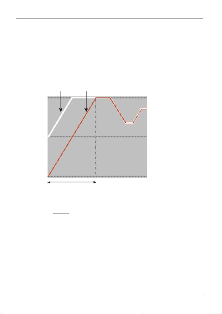
4.3.1 Set-point gradient / ramp
To prevent set-point step changes, parameter r set-point r r.SP can be adjusted to
a maximum rate of change. This gradient is effective in positive and negative direction..
With parameter r.SP set to OFF (default), the gradient is switched off and set-point
changes are realized directly.
(for parameter: see page 55)
4.3.2 Cooling functions
The configuration parameter CYCL (ConF/ Cntr/ CYCL) can be used for matching
the cycle time of 2-point and 3-point controllers. This can be done using the following 4
methods.
4.3.3 Standard ( CyCl= 0 )
The adjusted cycle times t1 and t2 are valid for 50% or -50% correcting variable. With
very small or very high values, the effective cycle time is extended to prevent unreasonably
9499-040-93811 / 59537-1 Page 42 of 88 Pro-16
Page 43

Configuration
short on and off pulses. The shortest pulses result from ¼ x t1 or ¼ x t2. The
characteristic curve is also called “bath tub curve”.
Parameters to be adjusted t1 : min. cycle time 1 (heating) [s]
( PArA/ Cntr) t2 : min. cycle time 2 (cooling) [s]
4.3.4 Switching attitude linear ( CyCl=1)
For heating (Y1), the standard method (see chapter 4.3.3) is used. For cooling (Y2), a
special algorithm for cooling with water is used.
Generally, cooling is enabled only at an adjustable process temperature (E.H2O),
because low temperatures prevent evaporation with related cooling, whereby damage to
the plant is avoided. The cooling pulse length is adjustable using parameter t.on and is
fixed for all output values.
The “off” time is varied dependent of output value. Parameter t.off is used for
determining the min “off” time. For output of a shorter off pulse, this pulse is suppressed,
i.e. the max. effective cooling output value is calculated according to formula
t.on / ( t.on + t.off) x 100%.
Parameters to be adjusted: E.H2O: minimum temperature for water cooling
( PArA / Cntr) t.on: pulse duration water cooling
t.off: minimum pause water cooling
level
9499-040-93811 / 59537-1 Page 43 of 88 Pro-16
Page 44

Configuration level
4.3.5 Switching attitude non-linear ( CyCl= 2 )
With this method, the cooling power
is normally much higher than the
heating power, i.e. the effect on the
behaviour during transition from
heating to cooling may be negative.
The cooling curve ensures that the
control intervention with 0 to -70% correcting variable is very weak. Moreover, the
correcting variable increases very quickly to max. possible cooling. Parameter F.H2O can
be used for changing the characteristic curve. The standard method (see section 4.3.3) is
also used for heating. Cooling is also enabled dependent of process temperature .
Parameters to be adjusted E.H2O: min. temperature for water cooling
( PArA / Cntr) t.on: Pulse duration water cooling
t.off: min. pause water cooling
F.H2O: adaptation of (non-linear)
characteristic Water cooling
9499-040-93811 / 59537-1 Page 44 of 88 Pro-16
Page 45

Configuration
level
4.3.6 Heating and cooling with constant period ( CyCl=3 )
The adjusted cycle times t1 and t2
are met in the overall output range . To
prevent unreasonably short pulses,
parameter tp is used for adjusting the
shortest pulse duration. With small
correcting values which require a pulse
shorter than the value adjusted in tp,
this pulse is suppressed. However, the
controller stores the pulse and totalizes
further pulses, until a pulse of duration
tp can be output.
Parameters to be adjusted t1 : Min. cycle time 1 (heating) [s]
( PArA/ Cntr) t2 : min. cycle time 2 (cooling) [s]
tp: min. pulse length [s]
9499-040-93811 / 59537-1 Page 45 of 88 Pro-16
Page 46

Configuration level
ConF/Cnt
SP.F
C.Fnc
C.Act
ConF/Out.1
O.Act
Y.1
PArA/Cnt
HYS.L
PArA/Cnt
HYS.H
PArA/SEtP
SP.LO
SP.Hi
4.4 Configuration examples
4.4.1 On-Off controller / Signaller (inverse)
r:
:
r:
r:
:
g
n
= 0 set-point /cascade controller
= 0 signaller with one output
= 0 inverse output action (e.g. heating applications)
= 0 output action Out.1 direct
= 1 control output Y1 active
= 0...9999 switching difference below SP
= 0...9999 switching difference above SP
= -1999...9999 lower set-point limit for Weff
= -1999...9999 upper set-point limit for Weff
For direct signaller action, the controller action must be changed
( ConF / Cntr / C.Act = 1 )
9499-040-93811 / 59537-1 Page 46 of 88 Pro-16
Page 47

ConF/Cnt
SP.F
C.Fnc
C.Act
ConF/Out.1
O.Act
Y.1
ConF/Out.3
O.tYP
Out.0
Out.1
O.Src
ti1
td1
t1
PArA/SEtP
SP.LO
SP.Hi
Configuration
level
4.4.2 2-point and continuous controller (inverse)
r
n
= 0 set-point / cascade controller
= 1 2-point and continuous controller (PID)
= 0 inverse action (e.g. heating applications)
:
= 0 action Out.1 direct
= 1 control output Y1 active
:
= 1 / 2 Out.3 Type ( 0/4 … 20mA)
= -1999...9999 scaling analog output 0/4mA
= -1999...9999 scaling analog output 20mA
= 1 controller output y1 (continuous)
PArA/Cntr: Pb1 = 1...9999 proportional band 1 (heating) in units of phys. quantity
(e.g. °C)
= 0,1...9999 integral time 1 (heating) in sec.
= 0,1...9999 derivative time 1 (heating) in sec.
= 0,4...9999 min. cycle time 1 (heating)
:
= -1999...999 set-point limit low for Weff
= -1999...9999 set-point limit high for Weff
For direct controller action, the controller action must be changed
g
( ConF / Cntr / C.Act = 1 )
9499-040-93811 / 59537-1 Page 47 of 88 Pro-16
Page 48

4.4.3 3-point and continuous controller
ConF/Cntr: SP.Fn
C.Fnc
C.Act
ConF/Out.1: O.Act
Y.1
Y.2
ConF/Out.2: O.Act
Y.1
Y.2
Conf/Out.3: O.typ
Out.0
Out.1
O.Src
PArA/Cntr: Pb1
Pb2
ti1
ti2
td1
td2
t1
t2
SH
PArA/SEtP: SP.O
SP.Hi
= 0
= 3
= 0
= 0
= 1
= 0
= 0
= 0
= 1
= 1 / 2
= 0
= 100
= 1
= 1...9999
= 1...9999
= 0,1...9999
= 0,1...9999
= 0,1...9999
= 0,1...9999
= 0,4...9999
= 0,4...9999
= 0...9999
= -1999...9999
= -1999...9999
Configuration level
set-point / cascade controller
3-point controller (2xPID)
action inverse (e.g. heating applications)
action Out.1 direct
control output Y1 active
control output Y2 not active
action Out.2 direct
control output Y1 not active
control output Y2 active
0 ... 20 mA continuous. / 4 ... 20 mA
scaling 0 %
scaling 100 %
controller output y1 (continuous)
proportional band 1 (heating) in units of phys. quantity (e.g. °C)
proportional band 2 (cooling) in units of phys. quantity (e.g. °C)
integral time 1 (heating) in sec.
derivative time 2 (cooling) in sec.
integral time 1 (heating) in sec.
derivative time 2 (cooling) in sec.
min. cycle time 1 (heating)
min. cycle time 2 (cooling)
neutr. zone in units of phys.quantity
set-point limit low for Weff
set-point limit high for Weff
9499-040-93811 / 59537-1 Page 48 of 88 Pro-16
Page 49

Configuration
4.4.4 3-point stepping controller (relay & relay)
ConF/Cntr: SP.Fn
C.Fnc
C.Act
ConF/Out.1: O.Act
Y.1
Y.2
ConF/Out.2: O.Act
Y.1
Y.2
PArA/Cntr: Pb1
ti1
td1
t1
SH
tP
tt
PArA/SEtP: SP.LO
SP.Hi
For direct action of the 3-point stepping controller, the controller output action
g
must be changed ( ConF / Cntr / C.Act = 1 )
= 0
= 4
= 0
= 0
= 1
= 0
= 0
= 0
= 1
= 1...9999
= 0,1...9999
= 0,1...9999
= 0,4...9999
= 0...9999
= 0,1...9999
= 3...9999
= -1999...9999
= -1999...9999
level
set-point / cascade controller
3-point stepping controller inverse action (e.g.
heating applications)
action Out.1 direct
control output Y1 active
control output Y2 not active
action Out.2 direct
control output Y1 not active
control output Y2 active
proportional band 1 (heating) in units of phys.
quantity (e.g. °C)
integral time 1 (heating) in sec.
derivative time 1 (heating) in sec.
min. cycle time 1 (heating)
neutral zone in units of phy. quantity
min. pulse length in sec.
actuator travel time in sec.
set-point limit low for Weff
set-point limit high for Weff
set-point / cascade controller
9499-040-93811 / 59537-1 Page 49 of 88 Pro-16
Page 50
Configuration level
4.4.5 - Y - Off controller / 2-point controller with pre-contact
ConF/Cntr: SP.Fn
C.Fnc
C.Act
ConF/Out.1: O.Act
Y.1
Y.2
ConF/Out.2: O.Act
Y.1
Y.2
PArA/Cntr: Pb1
ti1
td1
t1
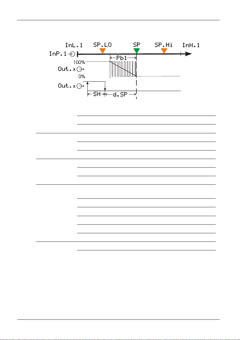
SH
d.SP
PArA/SEtP: SP.LO
SP.Hi
= 0
= 2
= 0
= 0
= 1
= 0
= 0
= 0
= 1
= 1...9999
= 0,1...9999
= 0,1...9999
= 0,4...9999
= 0...9999
= -1999...9999
= -1999...9999
= -1999...9999
set-point / cascade controller
D -Y-Off controller
inverse action (e.g. heating applications)
action Out.1 direct
control output Y1 active
control output Y2 not active
action Out.2 direct
control output Y1 not active
control output Y2 active
proportional band 1 (heating) in units of phys.
quantity (e.g. °C)
integral time 1 (heating) in sec.
derivative time 1 (heating) in sec.
min. cycle time 1 (heating)
switching difference
trigg. point separation suppl. cont.
D / Y / Off in units of phys. quantity
set-point limit low for Weff
9499-040-93811 / 59537-1 Page 50 of 88 Pro-16
Page 51

Configuration
4.4.6 KS 20-1 with measured value output
Example: KS20-10H-LR000-000
level
ConF/Out.3:O.tYP
= 2
= 3
= 4
Out.0 = -1999...9999
Out.1 = -1999...9999
O.Src = 3
= 1
Out.3 0...20mA continuous
Out.3
Out.3
Out.3
4...20mA continuous
0...10V continuous
2...10V continuous
Scaling Out.3 for 0/4mA e.g. 0/2V
Scaling Out.3 for 20mA e.g. 10V
Signal source for Out.3 is the process value
9499-040-93811 / 59537-1 Page 51 of 88 Pro-16
Page 52

5. Parameter-Level
5.1 Parameter-Overview
PArA Parameter level
È
Ì
Cntr
Control and self-tuning
Pb1 Pb12 SP.Lo InL.1 Inl.2 L.1 Pr.no
Pb2 Pb22 SP.Hi OuL.1 OuL.2 H.1
ti1 ti12 SP.2 InH.1 InH.2 HYS.1
ti2 ti22 r.SP OuH.1 OuH.2 dEl.1
td1 td12 t.SP tF.1 L.2
td2 td22 SP.bo H.2
t1 t.bo HYS.2
t2 Y.St dEl.2
SH SP.St L.3
Ù
Hys.l t.St H.3
Hys.H HYS.3
d.SP dEl.3
tP HC.A
tt
Y2
Y.Lo
Y.Hi
Y0
Ym.H
L.Ym
E.H2O
t.on
t.off
FH2o
PAr.2
Parameter-Level
2. set of parameters
SEtP Set-point and
process value
InP.1
Input 1
InP.2
Input 2
Lim
Limit value functions
ProG
Programmer
End
9499-040-93811 / 59537-1 Page 52 of 88 Pro-16
Page 53

Adjustment:
To access the parameter level, press the key Ù for 3 seconds and confirm using the
Ù -key subsequently. If the password function is activated, the prompt for the PASS is
displayed
The parameters can be adjusted using the ÌÈ - keys.
Press the
After the last parameter of a group, donE is displayed and followed by automatic
changing to the next group
Ù - key to change to the next parameter.
Parameter-Level
g Return to the beginning of a group, by pressing the Ù key for 3 sec.
g Unless a key is pressed during 30 seconds, the controller returns to the process
value and setpoint display (Time Out = 30 sec. )
g Resetting the configuration parameters to default
r chapter 86 (page 86)
5.2 Parameter
Cntr
Name Value range Description Default
Pb1
Pb2
ti1
ti2
td1
td2
t1
t2
SH
9499-040-93811 / 59537-1 Page 53 of 88 Pro-16
1...9999 1
1...9999 1
OFF/0,1...9999
OFF/0,1...9999
OFF/0,1...9999
OFF/0,1...9999
0,4...9999
0,4...9999
0...9999
Proportional band 1 (heating) in phys. dimensions (e.g. °C)
Proportional band 2 (cooling) in phys. dimensions (e.g. °C)
Integral action time 1 (heating) [s]
Integral action time 2 (cooling) [s]
Derivative action time 1 (heating) [s]
Derivative action time 2 (cooling) [s]
Minimal cycle time 1 (heating) [s]. The minimum impulse is
1/4 x t1
Minimal cycle time 2 (cooling) [s]. The minimum impulse is
1/4 x t2
Neutral zone or switching differential for on-off control
[phys. dimensions)
100
100
180
180
180
180
10
10
2
Page 54
t
ff
HYS.L
HYS.H
d.SP
tP
tt
Y2
Y.Lo
Y.Hi
Y.0
Ym.H
L.Ym
E.H2O
t.on
t.oFF
F.H2O
PAr.2
Name Value range Description Default
Pb12
Pb22
Ti12
Ti22
Td12
Td22
Parameter-Level
0...9999 Switching difference Low signaller [engineering unit] 1
0...9999 Switching difference High signaller [engineering unit] 1
-1999...9999
Trigger point seperation for additional contact / Y / Off
100
[phys. dimensions]
0,1...9999
3...9999
-100...100
-105...105
-105...105
-100...100
-100...100
0...9999
Minimum impulse [s]
Motor travel time [s]
2. correcting variable
Lower output limit [%]
Upper output limit [%]
Working point for the correcting variable [%]
Limitation of the mean value Ym [%] (see Fail page 28)
Max. deviation xw at the start of mean value calculation
OFF
60
0
0
100
0
5
8
[phys. dimensions]
-1999...9999
Min. temperature for water cooling. Below the set
120
temperature no water cooling happens.
0,1...9999
Impulse lenght for water cooling. Fixed for all values of
0,1
controller output.The pause time is varied.
1...9999
0,1...9999
Min. pause time for water cooling. The max. effective
controller output results from t.on/(
.on+t.o
)·100%
Modification of the (non-linear) water cooling characteristic
2
0,5
(see page 44)
1 Valid for ConF/ othr/ DP = 0. With DP = 1/ 2/ 3 also 0,1 / 0,01 / 0,001.
1...9999 1
Proportional band 1 (heating) in phys. dimensions (e.g. °C),
100
2. parameter set
1...9999 1
Proportional band 2 (cooling) in phys. Dimensions (e.g. °C),
100
2. parameter set
OFF/0,1...9999
OFF/0,1...9999
OFF/0,1...9999
OFF/0,1...9999
Integral action time 2 (cooling) [s], 2. parameter set
Integral action time 1 (heating) [s], 2. parameter set
Derivative action time 1 (heating) [s], 2. parameter set
Derivative action time 2 (cooling) [s], 2. parameter set
180
180
180
180
9499-040-93811 / 59537-1 Page 54 of 88 Pro-16
Page 55

SEtP
InP.1
InP.2
Parameter-Level
Name Value range Description Default
SP.LO
SP.Hi
SP.2
r.SP
SP.bo
t.bo
Y.St
SP.St
t.St
SP
g
Name Value range Description Default
InL.1
OuL.1
InH.1
OuH.1
t.F1
Name Value range Description Default
InL.2
OuL.2
InH.2
OuH.2
-1999...9999
-1999...9999
-1999...9999
OFF/0,01...9999
-1999...9999
0...9999
-120...120
-1999...9999
0...9999
-1999...9999
SP.Lo and SP.hi should be between the limits of rnGH and rnGL
see configuration r controller page 28
-1999...9999
-1999...9999
-1999...9999
-1999...9999
0,1...100
-1999...9999
-1999...9999
-1999...9999
-1999...9999
Set-point limit low for Weff
Set-point limit high for Weff
Set-point 2
Set-point gradient [/min]
Boost set-point (see page 72)
Boost time (see page 72)
Start-up correcting value (see page 71)
Set-point for start-up
Start-up hold time (see page 71)
Set-point (only visible with BlueControl!)
Input value for the lower scaling point
Displayed value for the lower scaling point
Input value for the upper scaling point
Displayed value for the lower scaling point
Filter time constant [s]
Input value for the lower scaling point
Displayed value for the lower scaling point
Input value for the upper scaling point
Displayed value for the upper scaling point
900
OFF
30
10
20
95
10
20
20
0,5
50
50
0
0
0
0
0
0
0
9499-040-93811 / 59537-1 Page 55 of 88 Pro-16
Page 56

Lim
Parameter-Level
Name Value range Description Default
L.1
H.1
HYS.1
dEL.1
L.2
H.2
HYS.2
dEL.2
L.3
H.3
HYS.3
dEL.3
HC.A
-1999...9999
-1999...9999
0...9999
0...9999
-1999...9999
-1999...9999
0...9999
0...9999
-1999...9999
-1999...9999
0...9999
0...9999
-1999...9999
Lower limit 1
Upper limit 1
Hysteresis limit 1
Alarm delay from limit value 1 [s]
Lower limit 2
Upper limit 2
Hysteresis limit 2
Alarm delay from limit value 2 [s]
Lower limit 3
Upper limit 3
Hysteresis limit 3
Alarm delay from limit value 3 [s]
Heat current limit [A]
-10
10
OFF
OFF
OFF
OFF
50
1
0
1
0
1
0
9499-040-93811 / 59537-1 Page 56 of 88 Pro-16
Page 57
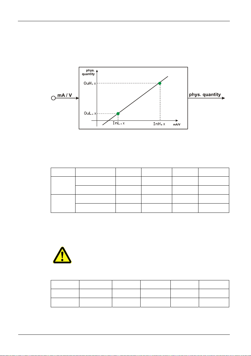
6. Input scaling
When using current or voltage signals as input variables for InP.1 or InP.2,
scaling of input and display values at parameter setting level is required. Specification of
the input value for lower and higher scaling point is in the relevant electrical unit (mA/ V).
Input Inp.1
Parameter InL.1 , OuL.1, InH.1 und OuH.1 are only visible if
g
ConF / InP.1 / Corr = 3 is chosen.
S.tYP Input signal InL.1 OuL.1 InH.1 OuH.1
30
(0...20mA)
40
(0...10V)
In addition to these settings, InL.1 and InH.1 can be adjusted in the range
(0...20mA / 0...10V) determined by selection of S.tYP .
0 … 20 mA DC
4 … 20 mA DC
0 … 10 V
2 … 10 V
For using the predetermined scaling with thermocouple and resistance
thermometer (Pt100), the settings of InL.1 and OuL.1 as well as of
InH.1 and OuH.1 must correspond.
Input
scaling
0 -1999...9999 20 -1999...9999
4 -1999...9999 20 -1999...9999
0 -1999...9999 10 -1999...9999
2 -1999...9999 10 -1999...9999
Input InP.2
S.tYP Input signal InL.2 OuL2 InH.2 OuH.2
30 0 … 20 mA DC
31 0 … 50 mA AC
In addition to these settings, InL.2 and InH.2 can be adjusted in the range
(0...20/ 50mA) determined by selection of S.tYP.
9499-040-93811 / 59537-1 Page 57 of 88 Pro-16
0 -1999...9999 20 -1999...9999
0 -1999...9999 50 -1999...9999
Page 58

7. Calibration level
Measured value correction ( CAL) is visible only if ConF /
g
InP.1 / Corr = 1 or 2 is selected.
To access the calibration level, press the key Ù for 3 seconds and then the key
Ì to select the CAL-Menu item. Press Ù to confirm.
If the password function is activated, a prompt for the PASS is displayed.
In the calibration menu ( CAL), the measured value can be adapted. Two methods are
available :
Offset correction ( ConF/ InP.1 / Corr =1 ):
Calibration level
InL.1: The input value of the scaling point is displayed.
0.0 The operator must wait, until the process is at rest. Subsequently, the
operator acknowledges the input value by pressing key
OuL.1: The display value of the scaling point is displayed.
0.0 Before calibration, OuL.1 is equal to InL.1.
The operator can correct the display value by pressing keys ÌÈ Subsequently, he
confirms the display value by pressing key Ù.
9499-040-93811 / 59537-1 Page 58 of 88 Pro-16
Ù.
Page 59

Calibration
level
Offset correction ( ConF/ InP.1 / Corr =1 ):
possible on-line at the process
2-point correction ( ConF/ InP.1 / Corr = 2):
InL.1: The input value of the lower scaling point is displayed. The operator must
0.0 adjust the lower input value by means of a process value simulator and
confirm the input value by pressing key
Ù.
OuL.1: The display value of the lower scaling point is displayed. Before
0.0 calibration, OuL.1 is equal to InL.1. The operator can correct the
lower display value by pressing the
ÌÈ keys. Subsequently, he
confirms the display value by pressing key Ù.
9499-040-93811 / 59537-1 Page 59 of 88 Pro-16
Page 60

Calibration level
Ì
InH.1: The input value of the upper scaling point is displayed. The operator must
0.0 adjust the upper input value by means of the process value simulator and
confirm the input value by pressing key Ù.
OuH.1: The display value of the upper scaling point is displayed. Before
0.0 calibration OuH.1 is equal to InH.1.The operator can correct the
upper display value by pressing keys
display value by pressing key Ù.
2-point correction ( ConF/ InP.1 / Corr = 2 ):
is possible off-line with process value simulator
ÌÈ Subsequently, he confirms the
The parameters (OuL.1, OuH.1) altered at CAL level can be reset by
decreasing them below the lowest adjustment value (OFF) using the
g
decrement key
9499-040-93811 / 59537-1 Page 60 of 88 Pro-16
.
Page 61

8. Programmer
8.1 Operation
Programmer operation (run/stop, preset and reset) is via è-Key-Menu, digital inputs or
interface (BlueControl, superordinate visualization, ...).
Operating via front keys
The function key è opens the function menu of the programmer. By using the arrow
buttons select a function. In order to exit the screen, either press the
automatically exit after 30 seconds.
Operation via digital inputs
Functions start/stop and reset can be activated also via digital inputs. For this, parameters
P.run and P.oFF must be set for digital inputs at CONF level LOGi.
Program/segment selection
Prerequisite: Programmer is in the reset or stop condition and program / segment selection
(Pr.no / Pr.SG) is set in the extended operating level.
How to select a defined program (Pr.no) followed by a segment (Pr.SG) is shown
below. When starting the programmer now, program operation starts at the beginning of
the selected segment in the selected program.
Programmer
è key, or it will
Preset
The preset function is activated via segment selection.
To permit preset in a running program, switch the programmer to stop, select the target
segment as described in the above section and switch the programmer to run.
9499-040-93811 / 59537-1 Page 61 of 88 Pro-16
Page 62

8.1.1 Programmer display
Programmer
Programmer is in reset and the internal controller setpoint is effective. Segment or program number and
OFF are displayed (configurable with BlueControl:
Configuration r Other r PDis3).
Programmer running (run LED is lit). Segment or
program number, segment type (/ rising; \ falling;
- hold) and program/segment rest time or runtime
are displayed (configurable with BlueControl:
Configuration r Other r PDis3).
Program end was reached. The set-point defined in
the last segment is effective. Segment or program
number and End are displayed (configurable with
BlueControl: Configuration r Other r PDis3).
Function key è was used to switch over to the
controller. The instantaneously effective correcting
variable is displayed.
8.1.2 Segment type
Rampsegment
(time)
Rampsegment
(gradient)
Hold
segment
Step
segment
9499-040-93811 / 59537-1 Page 62 of 88 Pro-16
With a ramp segment (time), the set-point runs
linearly from the start value (end of previous
segment) towards the target set-point (Sp) of the
relevant segment during time Pt (segment
duration).
With a ramp segment (gradient), the set-point
runs linearly from the start value (end value of
previous segment) towards the target value (Sp)
of the relevant segment. The gradient is
determined by parameter Pt.
With a hold segment, the end set-point of the
previous segment is output constantly during a
defined time which is determined by parameter
Pt.
With a step segment, the program set-point
goes directly to the value specified in parameter
Sp. With configured control deviation alarms,
the alarm is suppressed within band monitoring.
Page 63
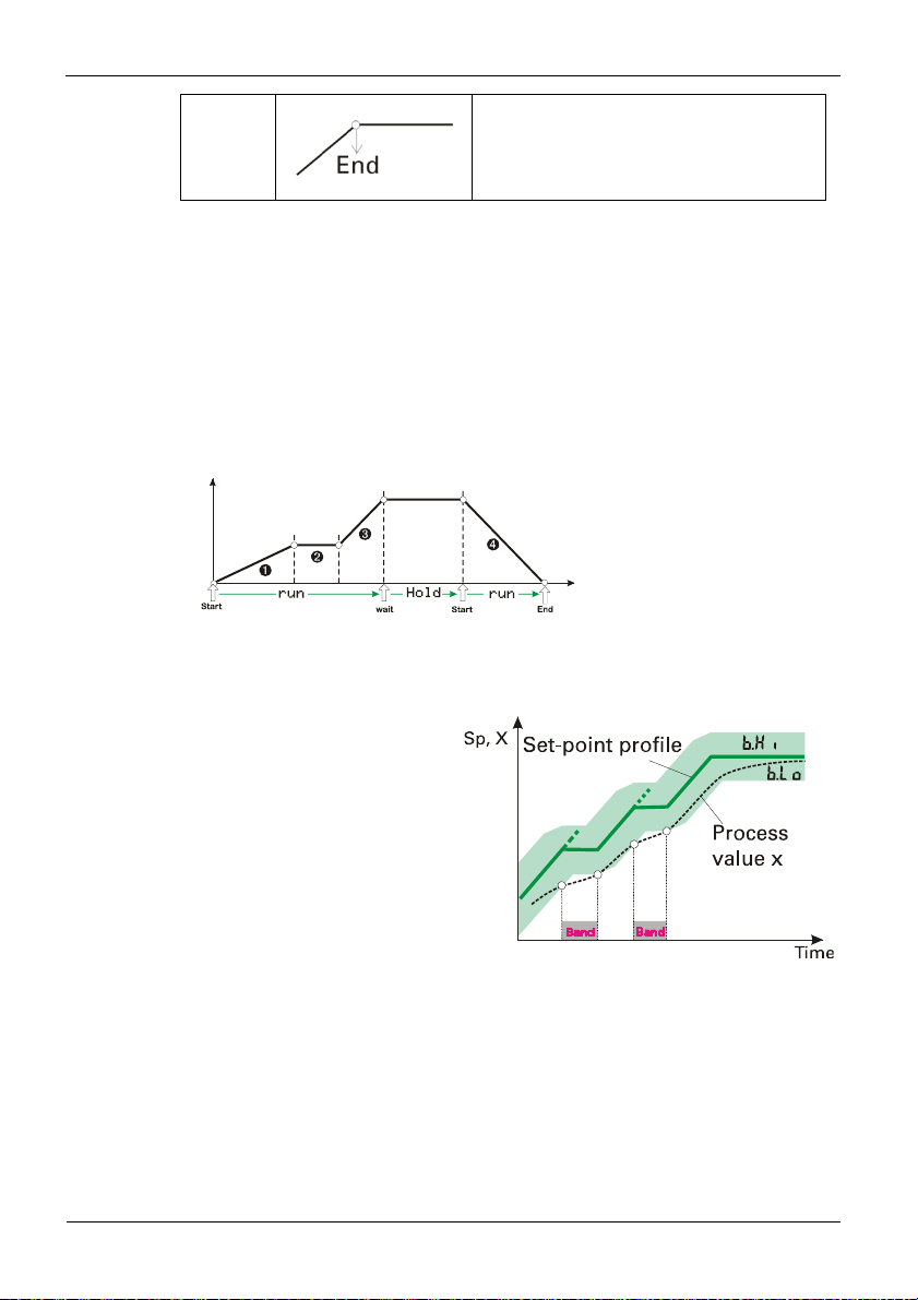
End
segment
Waiting and operator call
All segment types except end segment can be combined with ”Wait at the end and
operator call”.
If a segment with combination ”wait” was configured, the programmer goes to stop mode
at the segment end (run LED is off). Now, the programmer can be restarted by pressing the
start/stop key (>3s), via interface or digital input.
Programmer
The last segment in a program is the end
segment. When reaching the end segment,
output of the setpoint output last is continued.
1 Segment type = time
2 Segment type = hold
3 Segment type = time and wait
4 Segment type = time
8.1.3 Bandwidth monitoring
Bandwidth monitoring is valid for
all program segments. An
individual bandwidth can be
determined for each program.
When leaving the bandwidth
(b.Lo = low limit; b.Hi = high
limit), the programmer is stopped
(run LED flashes). The program
continues running when the
process value is within the
predefined bandwidth again.
With segment type Step and bandwidth monitoring activated, the control
deviation alarm is suppressed, until the process value is in the band again.
g
If band alarm signalling as a relay output is required, a control deviation alarm
with the same limits as the band limits must be configured.
9499-040-93811 / 59537-1 Page 63 of 88 Pro-16
Page 64

Programmer
8.1.4 Search run at programmer start
The programmer starts the first segment at the actual process value (search run). This may
change the effective runtime of the first segment.
8.1.5 Behaviour after mains recovery or sensor error
Mains recovery
After power recovery, the last program set-points and the time elapsed so far are not
available any more. Therefore, the programmer is reset in this case. The controller uses the
internal set-points and waits for further control commands (the run LED blinks).
Sensor error
With a sensor error, the programmer goes to stop condition (the run LED blinks). After
removal of the sensor error, the programmer continues running.
9499-040-93811 / 59537-1 Page 64 of 88 Pro-16
Page 65
b.lo
dst
b.hi
d.00
t
t
d
t
t
t
tout
8.2 Parameter overview
Prog Programmer level
Edit
Editing programs
prg
Copy
src
Programmer
Copying programs
End
È
Ì
ype
sp
p
.ou
···
ype
sp
p
Setting:
The parameters can be set by means of keys ÌÈ
Transition to the next parameter is by pressing key
After the last parameter of a group, donE is displayed and an automatic transition
the next group occurs
Return to the start of a group is by pressing key Ù during 3 sec. .
g
Unless a key is pressed during 30 sec. , the controller returns to process valueset-point display ( Time out = 30 sec. )
Ù
9499-040-93811 / 59537-1 Page 65 of 88 Pro-16
Page 66

8.3 Parameter
ProG
Name Value Range Description Default
b.Lo 0...9999
b.Hi 0...9999
d.00
tYPE
SP -1999...9999
Pt 0...9999
d.Out
tYPE
0
1
2
3
4
5
6
7
8
9
10
11
12
13
14
15
0
1
2
3
4
5
6
7
8
Programmer
Bandwidth lower limit
Bandwidth upper limit
Resetvalue of control track 1 ... 4
track 1= 0; track 2= 0; track 3= 0; track 4= 0
track 1= 1; track 2= 0; track 3= 0; track 4= 0
track 1= 0; track 2= 1; track 3= 0; track 4= 0
track 1= 1; track 2=1; track 3= 0; track 4=0
track 1= 0; track 2= 0; track 3= 1; track 4= 0
track 1= 1; track 2= 0; track 3= 1; track 4= 0
track 1= 0; track 2= 1; track 3= 1; track 4= 0
track 1= 1; track 2= 1; track 3= 1; track 4= 0
track 1= 0; track 2= 0; track 3= 0; track 4= 1
track 1= 1; track 2= 0; track 3= 0; track 4=1
track 1= 0; track 2= 1; track 3= 0; track 4= 1
track 1= 1; track 2= 1; track 3= 0; track 4= 1
track 1= 0; track 2= 0; track 3= 1; track 4= 1
track 1= 1; track 2= 0; track 3= 1; track 4= 1
track 1= 0; track 2= 1; track 3= 1; track 4= 1
track 1= 1; track 2= 1; track 3= 1; track 4= 1
segment type 1
time
gradient
hold
step
time and wait
gradient and wait
hold and wait
step and wait
end segment
segment end set-point 1
segment time/-gradient 1
control track 1...4 - 1 (see parameter d.00)
segment type 2 (see segment type 1)
-32000
-32000
0
0
0
9499-040-93811 / 59537-1 Page 66 of 88 Pro-16
Page 67

Programmer
Name Value Range Description Default
SP -1999...9999
Pt 0...9999
d.Out
tYPE
SP -1999...9999
Pt 0...9999
d.Out
tYPE
SP -1999...9999
Pt 0...9999
d.Out
tYPE
SP -1999...9999
Pt 0...9999
d.Out
tYPE
SP -1999...9999
Pt 0...9999
d.Out
tYPE
SP -1999...9999
Pt 0...9999
d.Out
tYPE
SP -1999...9999
Pt 0...9999
d.Out
•
•
•
•
•
•
tYPE
Pt 0...9999
d.Out
tYPE
SP -1999...9999
Pt 0...9999
d.Out
segment end set-point 2
segment time/-gradient 2
control track 1...4 - 2 (see parameter d.00)
segment type 3 (see segment type 1)
segment end set-point 3
segment time/-gradient 3
control track 1...4 - 3 (see parameter d.00)
segment type 4 (see segment type 1)
segment end set-point 4
segment time/-gradient 4
control track 1...4 - 4 (see parameter d.00)
segment type 3 (see segment type 1)
segment end set-point 5
segment time/-gradient 5
control track 1...4 - 5 (see parameter d.00)
segment type 6 (see segment type 1)
segment end set-point 6
segment time/-gradient 6
control track 1...4 - 6 (see parameter d.00)
segment type 7 (see segment type 1)
segment end set-point 7
segment time/-gradient 7
control track 1...4 - 7 (see parameter d.00)
segment type 8 (see segment type 1)
segment end set-point 8
segment time/-gradient 8
control track 1...4 - 8 (see parameter d.00)
• • • •
segment type 15 (see segment type 1)
segment time/-gradient 15
control track 1...4 - 15 (see parameter d.00)
segment type 16 (see segment type 1)
segment end set-point 16
segment time/-gradient 16
control track 1...4 - 16 (see parameter d.00)
0
0
0
0
0
0
•
•
0
0
9499-040-93811 / 59537-1 Page 67 of 88 Pro-16
Page 68

8.4 Programmer description
8.4.1 General
An overview of the most important features:
Programs: 16
Control outputs: 4
Segments: 16 per program
• Segment types: • ramp (set-point and time)
• ramp (set-point and gradient)
• hold segment (holding time)
• step segment (with alarm suppression)
• end segment
All segment types can be combined with ”Wait at the
end and call operator”
Time unit: configurable in hours:minutes or
minutes:seconds
Maximum segment
duration: 9999 hours = 1 year 51 days
Maximum program
duration: 16 x 9999 hours = > 18 years
Gradient: 0,01°C/h ( /min) to 9999°C/h ( /min)
Program name: 8 characters, adjustable via BlueControl software
Bandwidth control: bandwidth high and low (b.Lo,b.Hi) limits definable for each
program
Programmer
9499-040-93811 / 59537-1 Page 68 of 88 Pro-16
Page 69

8.4.2 Programmer set-up:
The instrument is factory-configured as a program controller. The following settings must
be checked:
Set-point function
For using the controller as a programmer, select parameter
ConF menu (r page 27).
Time base
The time base can be set to hours:minutes or minutes:seconds in the
parameter
Digital signals
For assigning a control output, program end or the operator call as a digital signal to
one of the outputs, set parameter
relevant output
Programmer operation
The programmer can be started, stopped and reset via one of the digital inputs
di1..4. Which input should be used for each function is determined by selecting
parameters
accordingly (r page 35).
Further settings, which affect the programmer display layout and operation are only
possible using the BlueControl software (see picture below)
Programmer
SP.Fn = 1 / 9 in the
ConF menu;
t.bAS (r page 29).
P.End, PrG1 … PrG4 or CALL to 1 for the
OUT.1 ...OUT.6 in menu ConF (r page 31 ff).
P.run and P.oFF = 2 - 5 or 7 -9 in the ConF menu Logi
Cutout from the BlueControl
®
Configuration “othr”
Programmer parameter setting
16 programmers with 16 segments each are available to the user. The relevant parameters
must be determined in menu ProG . (r page 66).
The procedure for editing a program is shown below.
Select the program you want to edit by means of keys ÌÈ and confirm it with Ù.
9499-040-93811 / 59537-1 Page 69 of 88 Pro-16
Page 70

Programmer
Start by setting the bandwidth high and low (b.Lo; b.Hi) limits and the control output
reset value (
d.00) for the selected program. The bandwidth is valid for all.
g Configuration parameter pCom (r page 40) can be used for display suppression of
bandwidth parameters and control output reset value, which, however, remains
valid.
Select the segment number (SEg; Segm.-No) for the segment which is to be edited.
Now, enter segment type, segment end set-point, segment time/gradient and control
output.
After confirming parameter d.Out with key Ù , select the following segment.
Copying a program
The procedure for copying a program is shown below.
When confirming function COPY with key Ù, the program which shall be copied must
be selected (Src). Subsequently, the target program (dSt) must be adjusted. Press key
Ù to start copying.
9499-040-93811 / 59537-1 Page 70 of 88 Pro-16
Page 71

9. Special functions
9.1 Start-up circuit
The start-up circuit is a special function for temperature control, e.g. hot runner control. Highperformance heating cartridges with magnesium oxyde insulation material must be heated
slowly to remove moisture and prevent destruction.
Operating principle:
1 After switching on the supply voltage, stabilised to the start-up set-point SP.St
is using a maximum start-up correcting value of Y.St.
2 The start-up holding time t.St is started one K below the start-up set-point
( SP.St-1K).
3 Subsequently, the process is lined out to set-point W.
4 If the process value drops by more than 40 K below the start-up set-point
(SP.St- 40K) due to a disturbance, the start-up procedure is re-started ( 5, 6, 7).
Special
functions
g With W < SP.St, W is used as set-point. The start-up holding time t.St is
omitted.
g If the gradient function (PArA/ SEtP/ r.SP OFF) was selected, start-up
value SP.St is reached with the adjusted gradient r.SP.
g With the boost function (see chapter 9.2 page 72) selected, W is increased by
SP.bo during time t.bo .
The following settings can be selected:
SP.Fn = 10 set-point + start-up circuit
The start-up circuit is effective only with the internal set-point.
SP.Fn = 11 set-point, SP.E /SP.2 + start-up circuit
The start-up circuit is effective also with the external set-point
SP.E and the 2nd set-point SP.2.
9499-040-93811 / 59537-1 Page 71 of 88 Pro-16
Page 72

9.2 Boost function
The boost function causes temporary increase of the set-point, e.g. for removing "frozen"
material from clogged die nozzles with hot-runner control.
If configured (r ConF/ LOGI/ booS), the boost function can be started via digital
input di1/2/3, with the function key on the instrument front panel or via the interface
(OPTION).
The set-point increase around boost set-point PArA /SEtP/SP.bo remains effective
as long as digital signal (di1/2 3, function key, interface) remains set. The maximum
permissible cycle time (boost time-out) is determined by parameter PArA
/SEtP/t.bo.
Unless reset after elapse of boost time I t.bo, the boost function is finished by the
controller.
Special functions
g The boost function also works with:
• start-up circuit: PArA /SEtP/ SP.bo is added to W after elapse of start-up
holding time PArA /SEtP/ t.St.
• Gradient function: set-point W is increased by PArA /SEtP/ SP.bo with gradient PArA
/SEtP/ r.SP.
9499-040-93811 / 59537-1 Page 72 of 88 Pro-16
Page 73

Special
9.3 KS 20-1 as Modbus-Master
This function is only selectable with the BlueControl engineering tool
Additions othr (only visible with BlueControl!)
Name Value range Description Default
MASt
0
1
Cycl 0...200
AdrO 1...65535
AdrU 1...65535
Numb 0...100
The controller can be used as Modbus master ( ConF / othr / MASt = 1 ).
The Modbus master sends its data to all slaves (broadcast message, controller adress 0). It
transmits its data (modbus adress AdrU) cyclic with the cycle time Cycl to the bus. The slave
controller receives the data transmitted by the master and allocates it to the modbus target
address AdrO.
If more than one data should be transmitted by the master controller ( Numb > 1) , the modbus
address AdrU indicates the start address of the data that should be transmitted and AdrO
indicates the first target address where the received data should be stored. The following data
will be stored at the next available modbus address.
With this it is possible e.g. to specify the process value of the master controller as set-point for
the slave controllers.
Controller is used as Modbus master
Slave
Master
Cycle time [ms] for the Modbus master to transmit its
data to the bus.
Target address to which the with AdrU specified data is
given out on the bus.
Modbus address of the data that Modbus master gives
to the bus.
Number of data that should be transmitted by the
Modbus master.
functions
60
0
1
1
0
9499-040-93811 / 59537-1 Page 73 of 88 Pro-16
Page 74

S
)
)
(
)
)
9.4 Linearization
Linearization for input INP1
The "Lin" parameter is valid if the following condition is met:
Dependent of input type, the input signals are specified in μV, [, mA or Volt dependent of
input type.
With up to 16 segment points, non-linear signals can be simulated or linearized. Every
segment point comprises an input (In.1 … In.16) and an output (Ou.1 …
Ou.16). These segment points are interconnected automatically by means of straight
lines.
The straight line between the first two segments is extended downwards and the straight
line between the two largest segments is extended upwards.
I.e. a defined output value is also provided for each input value. When switching an In.x
value to OFF, all other ones are switched off. Condition for these configuration
parameters is an ascending order.
In.1<In.2 < ...<In.16 und Ou.1<Ou.2 ...< Ou.16.
Special functions
S.tYP and
= 18 (Special linearization
= 23 (KTY11-6
Current
= 30
= 40 (Voltage
.Lin
----
---= 1: Special linearization
= 1: Special linearization
9499-040-93811 / 59537-1 Page 74 of 88 Pro-16
Page 75
9.5 Timer
9.5.1 Setting up the timer
Operating modes
6 different timer modes are available to the user. The relevant timer mode can be set via
parameter SP.Fn in the Conf menu (r page 27).
Mode 1 (–)
After timer start, control is to the adjusted set-point .
The timer (
enters or leaves the band around the set-point
(x = SP _ b.ti). After timer elapse, the controller
returns to
alternately in the lower display line.
Mode 2 (····)
Mode 2 corresponds to mode 1, except that control is continued with the relevant set-point
after timer (
Mode 3 (–)
After timer start, control is to the adjusted set-point. The
timer (
timer elapsing the controller switches off. End and the
set-point are displayed alternately in the bottom display
line.
Mode 4 (····)
Mode 4 corresponds to mode 3, except that control is continued with the relevant set-point
after timer (t.SP) elapse.
Mode 5 (delay)
The timer starts immediately. The controller output
remains on Y2. After timer (
with the adjusted set-point.
t.SP) runs as soon as the process value
Y2. End and the set-point are displayed
t.SP) elapse.
t.SP) starts immediately after switch-over. After
Special
functions
t.SP) elapse, control starts
Mode 6
After set-point switch-over (
SP.2. The timer (t.SP) starts when the process value
SPr SP.2), control is to
enters the adjusted band around the set-point
(x = SP.2 _ b.ti).
After time elapse the controller returns to
SP. End and
the set-point are displayed alternately in the lower
display line.
9499-040-93811 / 59537-1 Page 75 of 88 Pro-16
Page 76

Special functions
Tolerance band
Timer modes 1,2 and 6 are provided with a freely adjustable tolerance band. The tolerance
band around the set-point can be adjusted via parameter
SP.2 _ b.ti) (r page 27).
(x =
b.ti in the Conf menu
Timer start
Various procedures for starting the timer are possible:
Y2
di1
di2
di4
di1
di4
LOGI
SP.2
=
=
2 x
3 x
4 x
5 x
x 2
x 3
x 4
x 5
6 x
0 x
x 0
x x
x x
Start via
Y / Y2 — switch-over via digital input
1
di3
SP / SP.2 - switch-over via digital
input 1 di2
di3
Pressing key è and select Y
Power on
Changing
t.ti
(extending operation level)
Serial interface (if provided)
1 2 3 4 5 6
dddddd
dddddd
dddddd
dddddd
wwwwwd
wwwwwd
wwwwwd
wwwwwd
ddddd w
ddddd w
wwwwwd
dddddd
dddddd
Mode
1 when using a digital input, adjust parameter di.Fn = 2 ( ConF/ LOGI) (key function)
x no effect
Signal end
If one of the relays activates after the timer has elapsed, parameter
action
O.Act = 1 must be selected for the relevant output OUT.1 … OUT.3 in the
ConF menu (r page 32). If direct action is selected, the relevant output signals the active
TimE = 1 and inverse
timer.
9.5.2 Determining the timer run-time
The timer run-time can be determined via parameter t.SP in the PArA menu. The timer
run-time must be specified in minutes with one digit behind the decimal point (0,1 minutes
= 6 seconds).
Alternatively, the timer run-time can be determined directly at extended operating level (r
chapter 9.5.3).
9499-040-93811 / 59537-1 Page 76 of 88 Pro-16
Page 77

9.5.3 Starting the timer
Dependent of configuration, the timer start is as follows:
by a positive activation at one of digital inputs di1..3
by switching on the manual mode via
by switching on the controller (power On)
by changing the timer run-time t.ti > 0 (extended operating level)
via the serial interface
Display:
( End and setpoint are
displayed alternately)
g With active timer, the time can be adjusted by changing parameter t.ti at extended
operating level.
Special
functions
è - key
run-LED Signification
blinks
lit
timer is running
off
pressing any key
timer was started
timer is not running yet
timer was started
timer is off
timer has elapsed
deletion of
End display by
9499-040-93811 / 59537-1 Page 77 of 88 Pro-16
Page 78
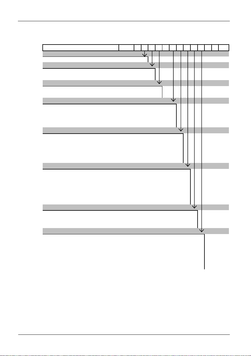
Ordering information
pply
T
y
R
0
0
0
0
10. Ordering information
Moedel Code KS20 - 1 x x - x x x x x 0 - 00
Model Typ
1/16 DIN; removable screw terminal block
Supply Voltage
100-240V AC 0
24VAC / 24VDC 1
Base Option
Transmitter Power Su
Heater Current / RSP input (mA) H
Option 1
Rela
(change over)
Single SSR A
Dual SSR Y
Linear mA/V DC Output L
Option 2
Not fitted
Relay (switch over) R
Dual Relay D
Single SSR A
Dual SSR Y
Option 3
Not fitted
Relay (switch over) R
Single SSR A
Dual SSR Y
Linear mA/V DC Output L
RS485 C
Option A
Not fitted
RS485 C
Dual isolated digital input B
Manual
No
manual
German (Full or concise manual) 1
English (Full or concise manual) 2
French (Full or concise manual) 3
Italian (concise manual) 4
Spanish (concise manual) 5
- TPS
9499-040-93811 / 59537-1 Page 78 of 88 Pro-16
Page 79
11. BlueControl®
BlueControl is the projection environment for the BluePort® controller series of
PMA. The following 3 versions with graded functionality are available:
FUNCTIONALITY MINI BASIC EXPERT
parameter and configuration setting yes yes Yes
controller and loop simulation yes yes yes
download: transfer of an engineering tot he controller yes yes yes
online mode / visualization SIM only yes yes
defining an application specific linearization yes yes yes
configuration in the extended operation level yes yes yes
upload: reading an engineering from the controller SIM only yes yes
basic diagnostic function no no yes
saving data file and engineering no yes yes
printer function no yes yes
online documentation, help yes yes yes
implementation of measurement value correction yes yes yes
data acquisition and trend display SIM only yes yes
wizard function yes yes yes
extended simulation no no yes
programmeditor no no yes
The mini version of BlueControl is available to download- free of charge - at
www.west-cs.com. At the end of the installation the licence number has to be stated or
DEMO mode must be chosen. At DEMO mode the licence number can be stated
subsequently under Help r Licence r Change.
BlueControl
®
9499-040-93811 / 59537-1 Page 79 of 88 Pro-16
Page 80

11.1 Configuration Port
The BluePort® interface is used to connect to the PC based BlueControl®
configuration tool.
The PC is connected via a mini USB adapter to the
device. The connector is located on top of the
housing (see picture)
a This is not a USB interface.
Only the connector has the
shape of a mini-USB connector!
BlueControl®
9499-040-93811 / 59537-1 Page 80 of 88 Pro-16
Page 81

Technical Data
12. Technical Data
INPUTS
Process value input INP1
Resolution: > 14 Bit (20.000 steps)
Decimal point: 0 to 3 digits behind the
decimal point
Dig. input filter: adjustable 0,0...100,0 s
Scanning cycle: 100 ms
Measured value correction:
2-point or offset correction
Thermocouples rTable 1 (page 83)
Input resistance: 1 M
Effect of source resistance: 1 V/
Cold-junction compensation: intern
max. additional error: <0,5 K
Sensor break monitoring
Sensor current: ß1 A
Configurable output action
Resistance thermometer
rTable 2 (page 83)
Connection: 2- or 3-wire
Lead resistance: max. 30 [
Input circuit monitor: Break and short circuit
Current and voltage signals
rTable 3 (page 83)
Span start, end of span: anywhere within
measuring range
Scaling: selectable -1999...9999
Linearization: 16 segments, adaptable with
BlueControl, decimal point: adjustable
input circuit monitor: 12,5% below span
start (2mA, 1V)
Accuracy: Better 0,1%
Supplementary input INP2
Heating current
transformer
Measuring range: 0...30 mA AC
Scaling: adjustable -1999..0,000..9999
Accuracy: Better than 0,25%
measurement via current
Current measuring range
Input resistance: ca. 120 [
Span: anywhere within 0 to 20mA
Scaliing: anywhere -1999...9999
Input circuit monitor: 12,5% below span start
(4..20mA r 2mA)
CONTROL INPUT DI1/DI2
Configurable as direct or inverse switch or pushbutton!
Connection of a potential-free contact suitable for
switching “dry“ circuits.
Switched voltage: 3.3 V
Switched current: < 10mA
Control inputs di3 & di4 (option)
Configurable as direct or inverse.
Nominal voltage: 24 V DC, external
Current sink (IEC 1131
Type 1)
Logic “0”: -3...5 V
Logic “1”: 15...30 V
Current requirement: approx. 5 mA
Transmitter supply UT (option)
Power: 22 mA / 18 V
OUTPUTS
Output used for:
Relay — option 1-3
Contacts: Potential free changeover
Max contact rating: 2A@ 250V 48…62Hz
Min contact rating: 6V, 1mA
Duty cycle: I = 1A/2A
250,000/150,000 @ 250V
resistive
Dual relay — option 2
Contacts: 2 NO contacts with shared
common
Max contact rating: 2A@ 250V 48…62Hz
Min contact rating: 6V, 1mA
Duty cycle: I = 1A/2A
500,000/200,000 @ 250V
resisitive
SSR - option 1-3
Voltage: 10 V into 500 Ω minimum
Dual SSR - option 1-3
Voltage 10 V into 500 Ω minimum
9499-040-93811 / 59537-1 Page 81 of 88 Pro-16
Page 82

Technical Data
Linear DC output option 1 & 3
Current output
0/4mA...20 mA, configurable.
Signal range: 0...approx. 22 mA
Load: ≤ 500 Ω
Load effect: none
Resolution: (0.1%)
Error: (0.2%)
0-10 V
Signal range: 0...11 V
Load: ≥ 2K Ω
Resolution: ≤ 0.1 %
Error: ≤ 0.2 %
Serial Interface
Physical: RS485, at 1200, 2400, 4800,
9600 or 19200 bps.
Protocol: Modbus RTU Communications
RS485 Option 3 or A
Transmitter supply
Output: 22 mA / ≥18 V
Note:
If the relays operate external contactors, these
must be fitted with RC snubber circuits to
manufacturer specifications to prevent excessive
switch-off voltage peaks.
POWER SUPPLY
Depending on version:
AC Supply
Voltage: 90...260 VAC
Frequency: 48...62 Hz
Power consumption approx. 7 VA
Universal supply 24 V UC
AC voltage: 20,4...26,4 VAC
Frequency: 48...62 Hz
DC voltage: 18...31 V DC
Power consumption: approx: 7 VA (W)
Behaviour with power failure
Configuration, parameters and adjusted
setpoints, control mode:
Non-volatile storage in EEPROM
ENVIRONMENTAL CONDITIONS
Protection modes
Front panel: IP 65 (NEMA 4X)
Housing: IP 20
Terminals: IP 20
Permissible temperatures
For specified accuracy: 0...60°C
Warm-up time: 15 minutes
Temperature effect: < 100ppm/K
For storage: -20...70°C
Humidity
75% yearly average, no condensation
Electromagnetic compatibility
Complies with EN 61 326-1 (for continuous, nonattended operation)
General
Housing
Material: Lexan PC940A
Flammability class:
Plug-in module, inserted from the front
UL 94 VO, self- extinguishing
Safety tests
Complies with EN 61010-1
Over voltage category II
Contamination class 2
Working voltage range 300 VAC
Protection class II
Certifications
cULus-certification: (Type 1, indoor use)
File: E 208286
Terminals 5mm Combicon
Mounting
Panel mounting with quick release fixing
mounting clamp (supplied).
9499-040-93811 / 59537-1 Page 82 of 88 Pro-16
Page 83

Technical Data
Table 1 Thermocouples measuring ranges
Thermocouple type Measuring range Accuracy Resolution (Ø)
L Fe-CuNi (DIN) -100...900°C -148...1652°F ß 2K 0,1 K
J Fe-CuNi -100...1200°C -148...2192°F ß 2K 0,1 K
K NiCr-Ni -100...1350°C -148...2462°F ß 2K 0,2 K
N Nicrosil/Nisil -100...1300°C -148...2372°F ß 2K 0,2 K
S PtRh-Pt 10% 0...1760°C 32...3200°F ß 2K 0,2 K
R PtRh-Pt 13% 0...1760°C 32...3200°F ß 2K 0,2 K
T Cu-CuNi -200...400°C -328...752°F ß 2K 0,05 K
C W5%Re-W26%Re 0...2315°C 32...4199°F ß 2K 0,4 K
D W3%Re-W25%Re 0...2315°C 32...4199°F ß 2K 0,4 K
E NiCr-CuNi -100...1000°C -148...1832°F ß 2K 0,1 K
B * PtRh-Pt6% 0(100)...1820°C 32(212)...3308°F ß 2K 0,3 K
* Specifications valid for 100°C
Table 2 Resistance transducer measuring ranges
Type Measuring current Measuring range Accuracy Resolution (Ø)
Pt100
-200...100°C -140...212°F ß 1K 0,1K
Pt100 -200...850°C -140...1562°F ß 1K 0,1K
Pt1000 -200...200°C -140...392°F ß 2K 0,1K
KTY 11-6 * -50...150°C -58...302°F ß 2K 0,05K
Special 0...4500
0,2mA
Special 0...450
Potentiometer 0...160
ß 0,1 % 0,01 %
Potentiometer 0...450
Potentiometer 0...1600
* Or special
Table 3 Current and voltage measuring ranges
Measuring range Input resistance Accuracy Resolution (Ø)
0-10 Volt
0-20 mA
~ 110 k
49 (voltage requirement ß 2,5 V)
ß 0,1 % 0,6 mV
ß 0,1 %
1,5 A
9499-040-093811 / 59537-1 Page 83 of 88 Pro-16
Page 84

13. Safety notes
This unit was built and tested in compliance with VDE 0411-1 / EN 61010-1 and was
delivered in safe condition.
The unit complies with European guideline 89/336/EWG (EMC) and is provided with CE
marking.
The unit was tested before delivery and has passed the tests required by the test schedule.
To maintain this condition and to ensure safe operation, the user must follow the hints and
warnings given in this operating manual.
The unit is intended exclusively for use as a measurement and control instrument in
technical installations.
Warning!
If the unit is damaged to an extent that safe operation seems impossible,
ELECTRICAL CONNECTIONS
The electrical wiring must conform to local standards (e.g. VDE 0100). The input
measurement and control leads must be kept separate from signal and power supply leads.
COMMISSIONING
Before instrument switch-on, check that the following information is taken into account:
Ensure that the supply voltage corresponds to the specifications on the type label.
All covers required for contact protection must be fitted.
If the controller is connected with other units in the same signal loop, check that the
The unit may be operated only in installed condition.
Before and during operation, the temperature restrictions specified for controller
SHUT-DOWN
For taking the unit out of operation, disconnect it from all voltage sources and protect it
against accidental operation.
If the controller is connected with other equipment in the same signal loop, check that
other equipment in the output circuit is not affected before switch-off. If necessary,
suitable protective measures must be taken.
the unit must not be taken into operation.
equipment in the output circuit is not affected before switch-on. If necessary,
suitable protective measures must be taken.
operation must be met.
Safety notes
9499-040-093811 / 59537-1 84 Page 84 of 88 9499-040-0 Pro-16
Page 85

MAINTENANCE, REPAIR AND MODIFICATION
The units do not need particular maintenance.
Warning!
When opening the units, or when removing covers or components, live parts
and terminals may be exposed.
Before starting this work, the unit must be disconnected completely.
After completing this work, re-shut the unit and re-fit all covers and components. Check if
specifications on the type label must be changed and correct them, if necessary.
Caution!
When opening the units, components which are sensitive to electrostatic
discharge (ESD) can be exposed. The following work may be done only at
workstations with suitable ESD protection.
Modification, maintenance and repair work may be done only by trained and
authorized personnel. For this purpose, the West Control Solutions / PMA
service department service should be contacted.
Cleaning
Should cleaning be necessary, the front panel should be cleaned by washing
with warm soapy water and drying immediately using a dry, lint free cloth.
9499-040-093811 / 59537-1 Page 85 of 88 Pro-16
Page 86

Safety notes
13.1 Resetting to factory setting
In case of faultyconfiguration, KS20-1 can be reset to the default condition.
1
ÈÌ + Power on
2
È
3
Ù
4
1 For this, the operator must keep the UP and DOWN keys pressed during
power-on.
2 Then, press UP key to select YES.
3 Confirm factory resetting with Enter and the copy procedure is started
(display COPY).
4 Afterwards the device restarts.
In all other cases, no reset will occur (timeout).
g If one of the operating levels was blocked and the safety lock is open, reset to
factory setting is not possible.
g If a pass number was defined (via BlueControl® ) and the safety lock is open, but no
operating level was blocked, enter the correct pass number when prompted in 3. A
wrong pass number aborts the reset action.
g The copy procedure ( COPY) can take some seconds. Now, the transmitter is in
normal operation.
9499-040-093811 / 59537-1 86 Page 86 of 88 9499-040-0 Pro-16
Page 87

9499-040-093811 / 59537-1 Page 87 of 88 Pro-16
Page 88

Austria China France
PMA Prozeß- und MaschinenAutomation GmbH
Liebermannstraße F01
2345 Brunn am Gebirge
Tel.: +43 (0)2236 691-121
Fax: +43 (0)2236 691-102
Email: info@west-cs.com
Danaher Setra-ICG
Tianjin Co. Ltd. No. 28 Wei 5 Road
The Micro-Electronic Industry Park TEDA Xiqing
District • Tianjin 300385
Tel.: +86 22 8398 8098 • Sales: +86 400 666 1802
Fax: +86 22 8398 8099
Email: tc.sales@danaher.com
WEST Control Solutions
France
Tel.: +33 (1) 77 80 90 40
Fax: +33 (1) 77 80 90 50
Email: info@west-cs.com
Germany United Kingdom United States
PMA Prozeß- und MaschinenAutomation GmbH
Miramstraße 87
34123 Kassel
Tel.: +49 (0)561 505-1307
Fax: +49 (0)561 505-1710
Email: info@west-cs.com
9499-040-093811 / 59537-1 88 Page 88 of 88 9499-040-0 Pro-16
WEST Control Solutions
The Hyde Business Park
Brighton • East Sussex •
BN2 4JU
Tel.: +44 (0)1273 606271
Fax: +44 (0)1273 609990
Email: info@west-cs.com
WEST Control Solutions
1675 Delany Road
Gurnee • IL 60031-1282
Tel.: 800 866 6659
Fax: 847 782 5223
Email: custserv.west@dancon.com
 Loading...