

Page 1
1
-DIN,
4
1
-DIN &
8
1
-DIN
16
TEMPERATURE CONTROLLERS
Product Manual
59125-3
Page 2

PREFACE
This manual comprises two volumes:
Volume 1: This supports normal operation of the
1
-DIN,
4
1
-DIN and
8
1
16
-DIN
Temperature Controllers. In normal operation, all actions taken
by the user are to be in front of the panel.
Volume 2: This supports the installation, commissioning and configuring of
the
1
-DIN,
4
1
-DIN and
8
1
-DIN Temperature Controllers. It is
16
intended for use only by personnel who are trained, equipped
and authorised to carry out these functions.
Page 3

59125
1
-DIN,
4
1
-DIN &
8
1
1 6
-DIN
TEMPERATURE CONTROLLERS
PRODUCT MANUAL
VOLUME 1
OPERATING INSTRUCTIONS
In normal operation, the operator must not remove the
Controller from its housing or have unrestricted access to
the rear terminals, as this would provide potential contact
with hazardous live parts.
Installation and configuration must be undertaken by
technically-competent servicing personnel. This is covered
in Volume 2 of this manual.
Contents - Volume 1
1 OPERATOR MODE 1-1
1.1 INTRODUCTION 1-1
1.2 DISPLAYS AVAILABLE 1-2
1.3 ADJUSTING THE SETPOINT/SETPOINT RAMP RATE 1-3
1.4 ALARM STATUS DISPLAY 1-3
1.5 OVER-RANGE/UNDER-RANGE DISPLAYS 1-4
1.6 SENSOR BREAK INDICATION 1-4
1.7 MANUAL CONTROL MODE 1-4
1.8 PRE-TUNE FACILITY 1-5
1.9 SELF-TUNE FACILITY 1-6
1.10 VIEWING THE HARDWARE DEFINITION CODE 1-7
O054-V1 (iii)
Page 4

59125
2 SET UP MODE 2-1
2.1 ENTRY INTO SET UP MODE 2-1
2.2 SET UP MODE PARAMETERS 2-2
2.3 OPERATOR MODE DISPLAYS 2-13
2.4 TUNING THE CONTROLLER MANUALLY 2-13
2.5 SELF-TUNE AND PRE-TUNE FACILITIES 2-14
2.6 EXIT FROM SET UP MODE 2-15
3 RS485 SERIAL COMMUNICATIONS 3-1
3.1 COMMUNICATIONS ENABLE/DISABLE 3-1
3.2 PHYSICAL REQUIREMENTS 3-1
3.3 INDIVIDUAL PARAMETERS 3-5
3.4 ERROR RESPONSE 3-10
(iv ) O054-V1
Page 5
59125
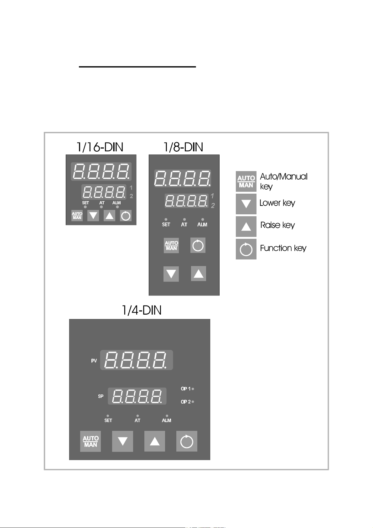
1 OPERATOR MODE
1.1 INTRODUCTION
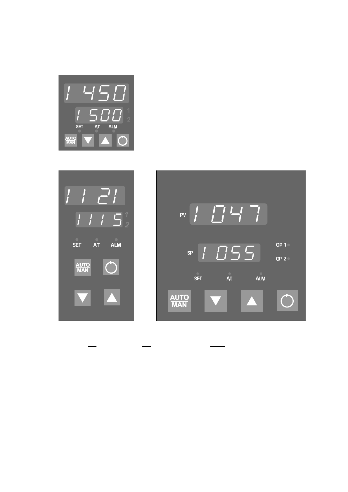
This Section covers the routine operation of the Controller, once it has been
installed and configured as described in Volume 2 of this manual. The Controller
front panel indicators and keys are shown in Figure 1-1.
Figure 1-1 Front Panel Controls and Indicators
O054-1 1-1
Page 6
59125
1.2 DISPLAYS AVAILABLE
After the Controller has performed its power-up self-test (during which, if the
Function key is held down during power-up, the current Controller firmware
revision is displayed), the initial displays appear. The available displays are
dependent upon (a) whether the Controller has been configured for Single
Setpoint operation or Dual Setpoint operation and (b) the setting of the Setpoint
Strategy parameter in Set Up Mode.
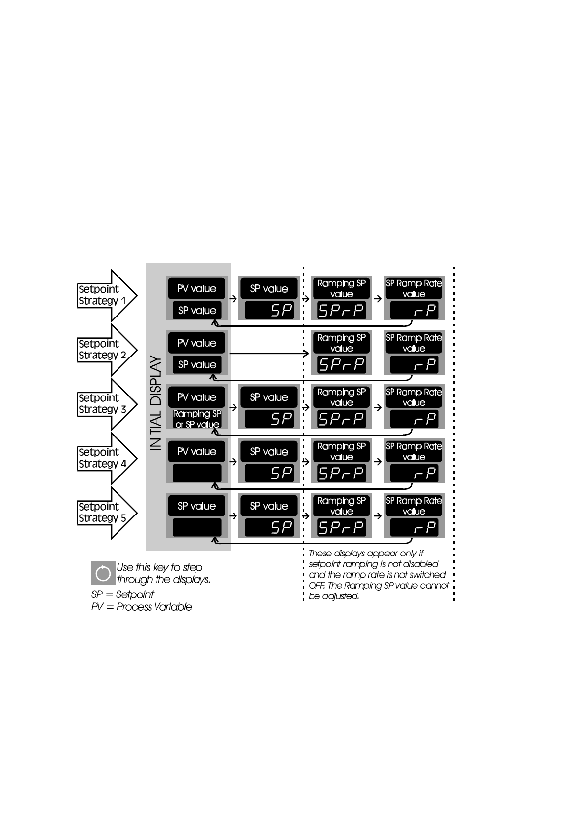
1.2.1 Single Setpoint Operation
In single setpoint operation, the available displays are:
1 -2 O054-1
Page 7
59125
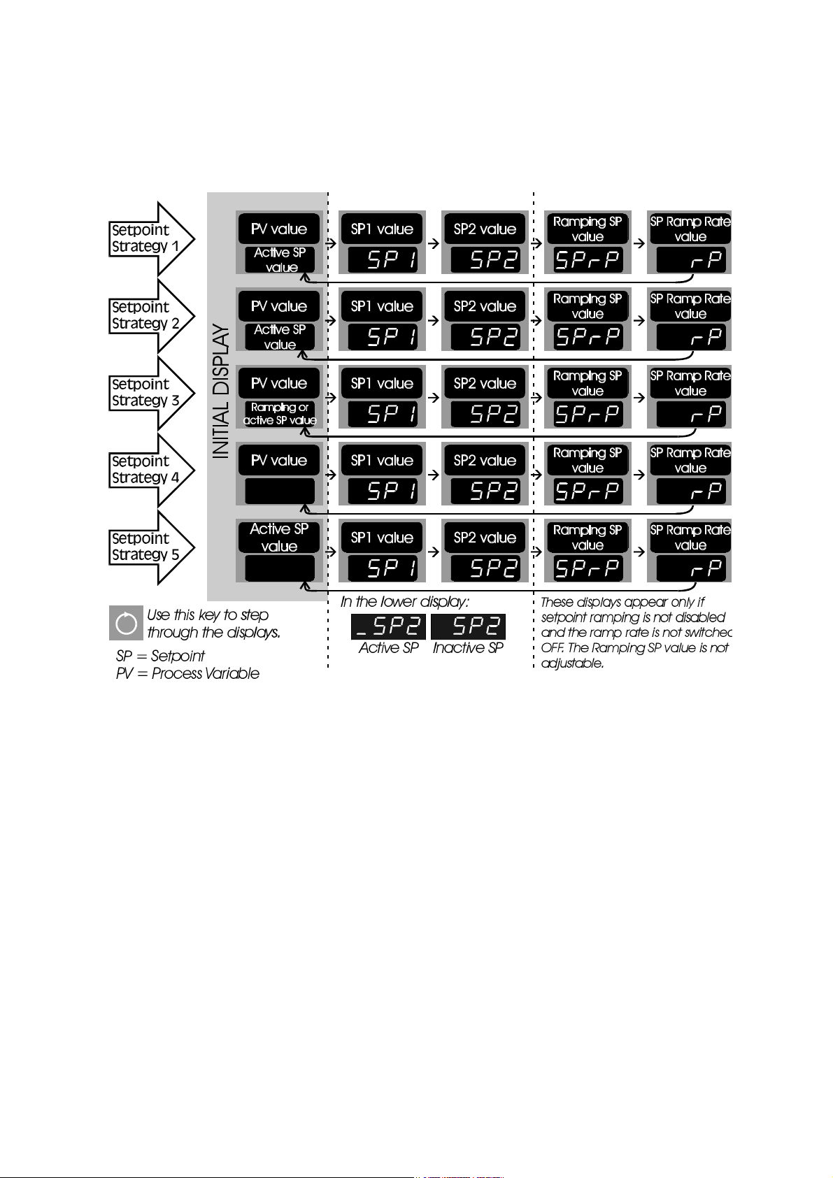
1.2.2 Dual Setpoint Operation
In dual setpoint operation, the available displays are:
1.3 ADJUSTING THE SETPOINT/SETPOINT RAMP RATE
The setpoint/setpoint ramp rate (whichever is selected - see previously) may be
adjusted using the Raise/Lower keys. The ramp rate may be adkusted in the range
1 to 9999. Any attempt to increase the ramp rate value beyond 9999 will cause
the upper display to go blank and setpoint ramping to be switched OFF. Setpoint
ramping can be resumed by decreasing the ramp rate value to 9999 or less.
1.4 ALARM STATUS DISPLAY
If one or more of the Controller’s alarms is (are) active, the alarm status display is
included in the available display sequence. The Alarm Status display is selected
by depressing the Function key repeatedly until the display appears (see Figure
1-2).
O054-1 1-3
Page 8
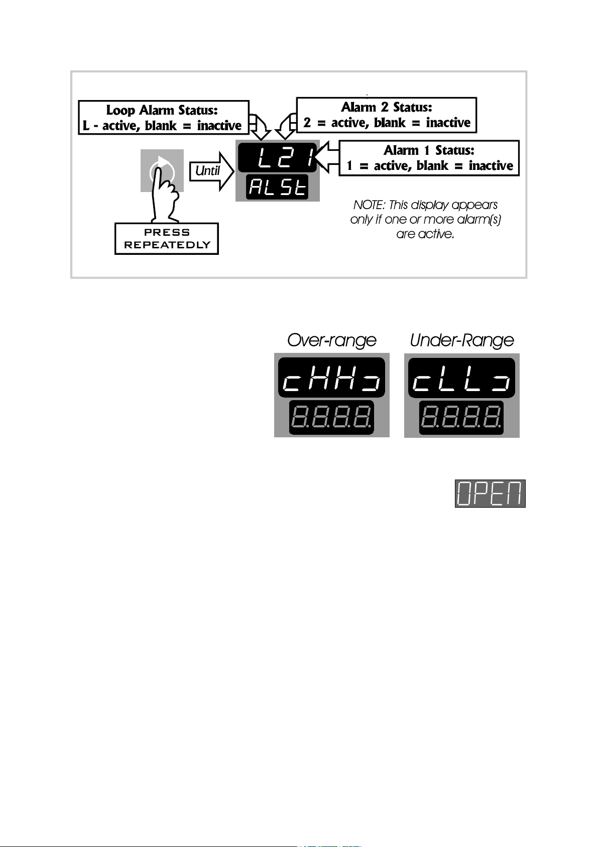
Figure 1 -2 Alarm Status Display
1.5 OVER-RANGE/UNDER-RANGE DISPLAYS
59125
The upper display will indicate if
the process variable is higher
than the input scale maximum
limit (over-range), or lower than
the input scale minimum limit
(under-range) as shown on the
right.
1.6 SENSOR BREAK INDICATION
If a break is detected in the sensor circuit, the upper display shows:
The reaction of the outputs and alarms to a detected sensor break is dependent
upon the input type and is defined in Appendix A.
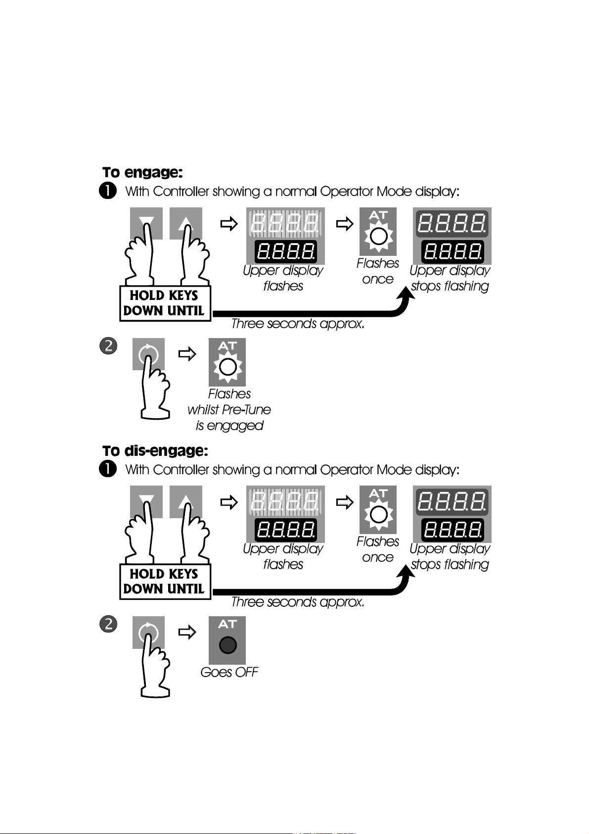
1.7 MANUAL CONTROL MODE
If selection of Manual Control Mode is enabled, the Manual Control Mode may
be entered (via a bumpless transfer) by depressing the Auto/Manual key. The SET
indicator will then flash continuously whilst the Controller is in Manual Control
Mode. The output power will then be displayed and may be adjusted with the
Raise/Lower keys.A return can be made to Automatic Control Mode (via a
bumpless transfer) by simply depressing the Auto/Manual key again, which causes
the usual process variable display to appear.
1 -4 O054-1
Page 9
59125
1.8 PRE-TUNE FACILITY
This facility may be used to set the Controller’s PID parameters to values which are
approximately correct, in order to provide a base from which the Self-Tune facility
may subsequently optimise tuning. Pre-Tune may be engaged (and subsequently
dis-engaged) as follows:
NOTE: The Pre-Tune facility will not engage if (a) the setpoint is currently
ramping, (b) the process variable is within 5% of input span of the setpoint,
or (c) an erroneous key sequence is used.
O054-1 1-5
Page 10
59125
Since Pre-Tune is a single-shot operation, it will automatically dis-engage
itself once the operation is complete.
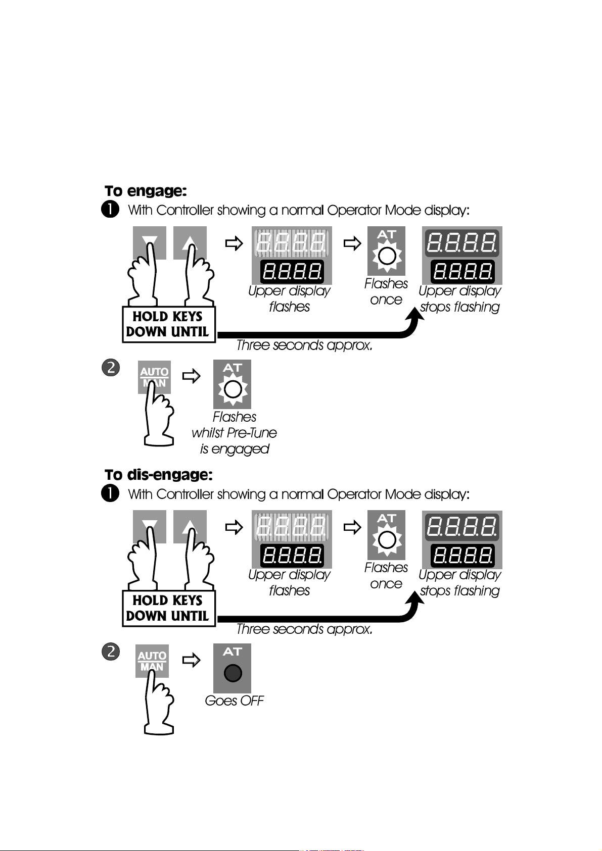
1.9 SELF-TUNE FACILITY
This facility is be used to optimise tuning whilst the Controller is operating. Self-Tune
may be activated as follows:
1-6 O054-1
Page 11
59125
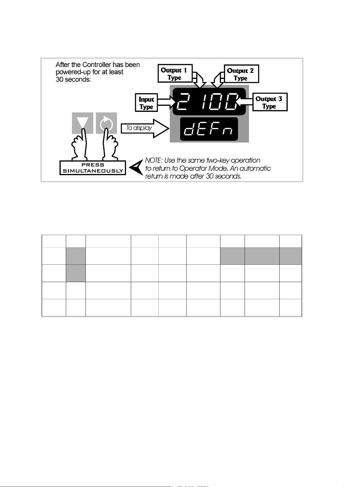
1.10 VIEWING THE HARDWARE DEFINITION CODE
Figure 1 -3 Viewing the Hardware Definition Code
NOTE: An automatic return is made to the normal Operator Mode
display after 30 seconds.
The Hardware Definition Code has the following significance:
Value 0 1 2 3 4 5 7 8
Input RTD/
Linear DC (mV)
Output
1
Output 2Not
fitted
Output 3Not
fitted
Relay SSR
Relay SSR
Relay SSR
Thermo-
couple
DriveDC(0 - 10V)DC(0 - 20mA)DC(0 - 5V)DC(4 - 20mA)
DriveDC(0 - 10V)DC(0 - 20mA)DC(0 - 5V)DC(4 - 20mA)
DriveDC(0 - 10V)DC(0 - 20mA)DC(0 - 5V)DC(4 - 20mA)
Linear
DC (mA)
Linear DC
(V)
Solid
State
Solid
State
Solid
State
O054-1 1-7
Page 12
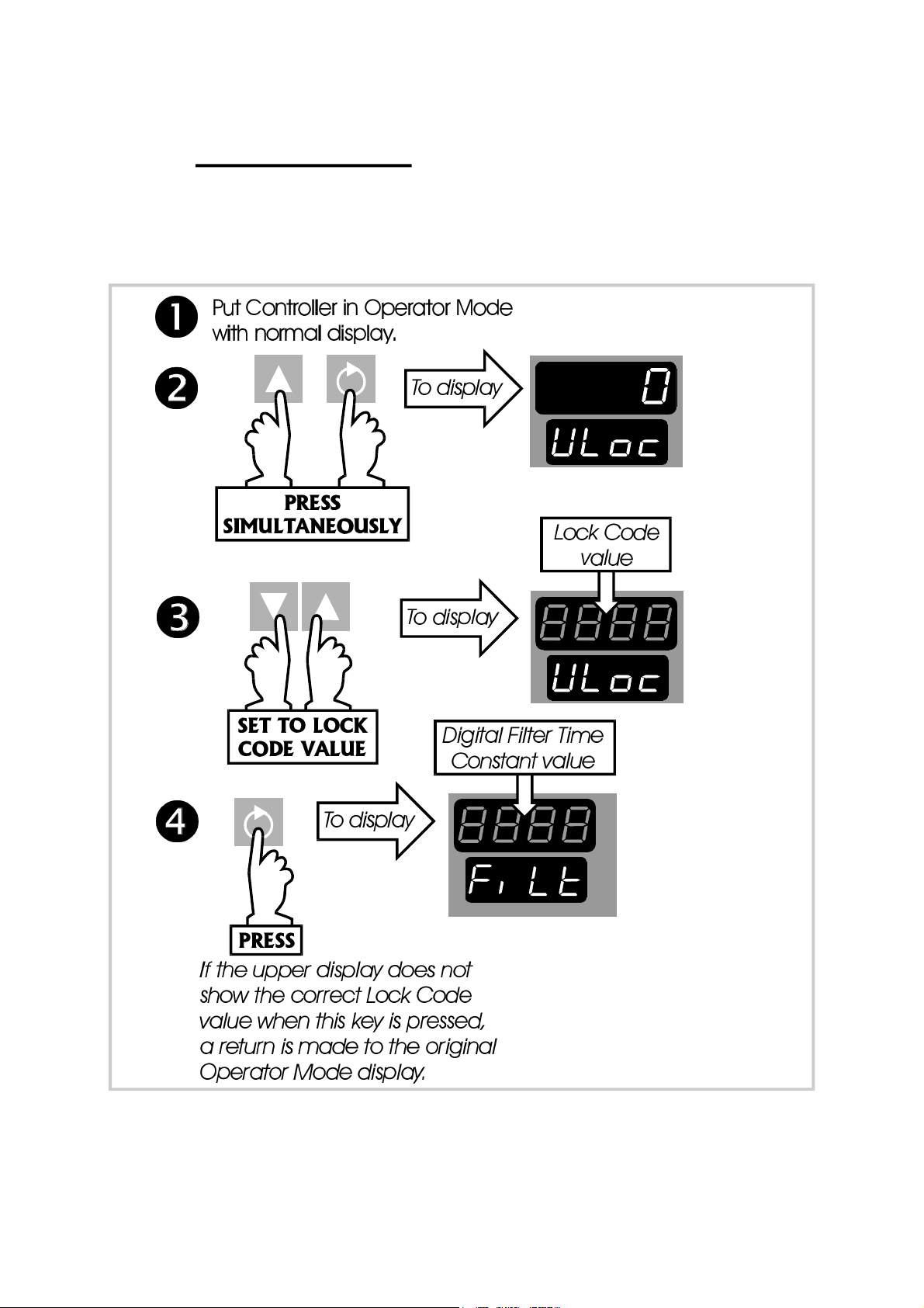
2 SET UP MODE
2.1 ENTRY INTO SET UP MODE
See Figure 2-1.
59125
Figure 2-1 Entry into Set Up Mode
2-1 O054-2
Page 13

59125
NOTE: If, on entry into Set Up Mode, the upper
display initially shows all decimal point
positions illuminated), this indicates that one
or more of the critical configuration
parameters - typically input range or output
use/type - have been altered in value/setting and, as a consequence, all
Set Up Mode parameters have been automatically set to their default
values/settings. To clear this display, simply alter the value/setting of any Set
Up Mode parameter (see below).
2.2 SET UP MODE PARAMETERS
The parameter sequence for view/adjustment in Set Up Mode is shown in Table
2 -1 . Use the Function key to step through the parameters. In each case, the
legend will be shown in the lower display and the current value/setting will be
shown in the upper display. The value/setting may be altered using the
Raise/Lower keys. A detailed description of each of these parameters is given in
the following Subsections.
2.2.1 Input Filter Time Constant
The Controller input is equipped with a digital filter which is used to filter out any
extraneous impulses on the process variable. This filtered PV is used for all
PV-dependent functions (control, alarms etc.).
CAUTION: If this parameter value is set excessively high, the control quality
may be significantly impaired. The value chosen should be sufficiently
large to attenuate stray noise on the process variable signal but no larger.
2.2.2 Process Variable Offset
This parameter is used to modify the actual process variable value (measured at
the Controller’s input terminals) in the following manner:
Offset PV value = Actual PV value + Process Variable Offset value.
For Controllers fitted with a linear input, the displayed process variable value is
limited by Scale Range Maximum (see Subsection 2.2.30) and Scale Range
Minimum (see Subsection 2.2.31). The offset process variable value is used for all
PV-dependent functions (control, display, alarm, recorder output etc.).
NOTE: This parameter value should be chosen with care. Any
adjustment to this parameter is, in effect, a calibration adjustment.
Injudicious application of values to this parameter could lead to the
displayed process variable value bearing no meaningful
relationship to the actual process variable value. There is no front
panel indication when this parameter is in effect (i.e. has been set
to a non-zero value).
O054-2 2-2
Page 14
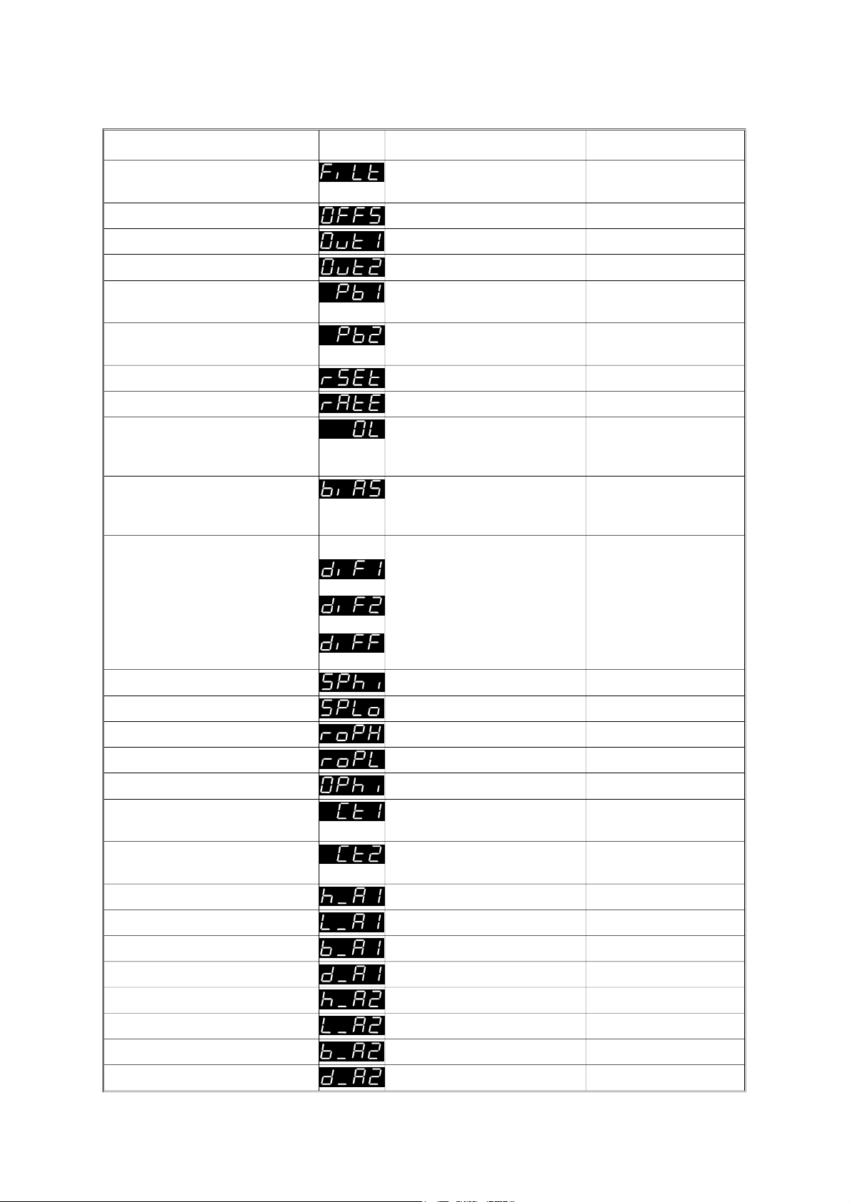
Table 2 -1 Set Up Mode Parameters
Parameter Legend Adjustment Range Default Value
59125
Digital Filter Time Constant OFF, 0.5 to 100.0 secs. In
2.0 seconds
0.5 sec. increments
Process Variable Offset
Span of Controller 0
±
Output Power 0 to 100% Read only
Output Power 2
Proportional Band 1 0.0 (ON/OFF control) to
5
0 to 100% Read only
10.0%
999.9% of input span
Proportional Band 2
15,
0.0 (ON/OFF control) to
10.0%
999.9% of input span
Reset (Integral Time Const.)
Rate (Derivative Time Const.)
Overlap/Deadband
15,
1
1
1s to 99m 59s and OFF 5m 00s
00s to 99m 59s 1m 15s
-20% to +20% (of
0%
Proportional Band 1 +
Proportional Band 2)
Manual Reset (Bias)
1
0% to 100% (Output 1 only)
25%
-100% to +100% (Output 1
& Output 2)
ON/OFF Differential
2
0.1% to 10.0% of input span 0.5%
Output 1 only
Output 2 only
Output 3 only
5
5
Setpoint High Limit Setpoint to Range Maximum Range Maximum
Setpoint Low Limit Range Minimum to Setpoint Range Minimum
Recorder Output Scale Max. -1999 to 9999 Range Maximum
Recorder Output Scale Min. -1999 to 9999 Range Minimum
Output 1 Power Limit
Output 1 Cycle Time 0.5, 1, 2, 4, 8, 16, 32, 64,
1
0% to 100% of full power 100%
32 secs.
128, 256 or 512 secs.
Output 2 Cycle Time 0.5, 1, 2, 4, 8, 16, 32, 64,
32 secs.
128, 256 or 512 secs.
Process High Alarm 1 value
Process Low Alarm 1 value
Band Alarm 1 value
3
Deviation Alarm 1 value
Process High Alarm 2 value
Process Low Alarm 2 value
Band Alarm 2 value
3
Deviation Alarm 2 value
3
3
Range Min. To Range Max. Range Max.
Range Min. To Range Max. Range Min.
0 to span from Limit SP 5 units
3
3
3
±Span from Limit SP 5 units
Range Min. To Range Max. Range Max.
Range Min. To Range Max. Range Min.
0 to span from Limit SP 5 units
3
±Span from Limit SP 5 units
2-3 O054-2
Page 15
59125
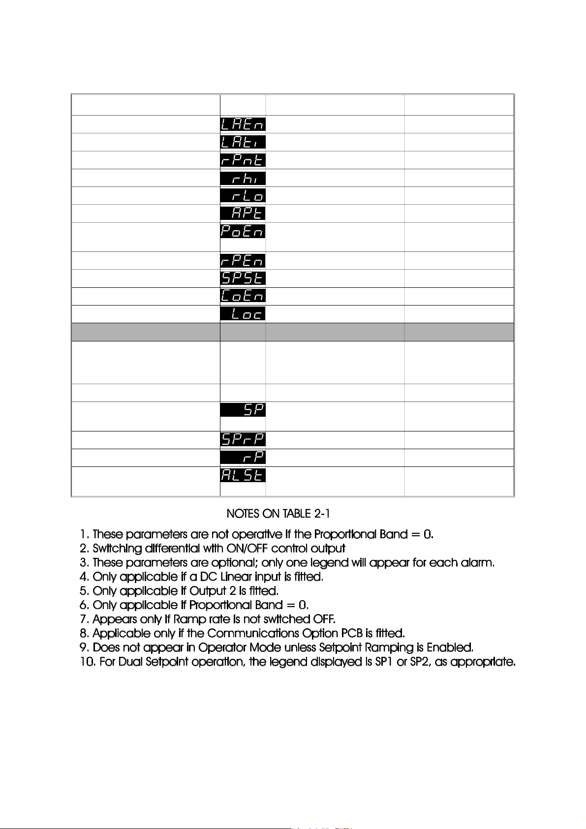
Table 2 -1 Set Up Mode Parameters (cont.)
Parameter Legend Adjustment Range Default Value
Loop Alarm Enable 0 (Disabled) or 1 (Enabled) 0
Loop Alarm Time
Scale Range Decimal Point
Scale Range Maximum
Scale Range Minimum
Auto Pre-Tune Enable/Disable 0 (Disabled) or 1 (Enabled) 0
6
4
4
4
1s to 99m 59s 99m 59s
0, 1, 2 or 3 1
-1999 to 9999 1000
-1999 to 9999 0000
Manual Control
0 (Disabled) or 1 (Enabled) 0
Enable/Disable
Setpoint Ramp Enable/Disable 0 (Disabled) or 1 (Enabled) 0
Setpoint Strategy 1, 2, 3, 4 or 5 1
Communications Enable
8
0 (Disabled) or 1 (Enabled) 1 (Enabled)
Lock Code 0 to 9999 10
Operator Mode Displays
(still accessible in Set Up
Mode):
Process Variable Read Only -
Setpoint
10
Setpoint Low Limit to Setpoint
Setpoint Low Limit
High Limit
Ramping Setpoint value
Setpoint Ramp Rate
Alarm Status Read Only (see Subsection
7
9
Read only
1 to 9999 and OFF OFF (blank)
-
1.3)
O054-2 2-4
Page 16

59125
2.2.3 Output Power 1
This parameter is the current Output 1 power level. It is a “Read Only” parameter
and is not adjustable.
2.2.4 Output Power 2
This parameter is the current Output 2 power level (if Output 2 is fitted). It is a
“Read Only” parameter and is not adjustable. If Output 2 is not fitted, this
parameter display is not applicable.
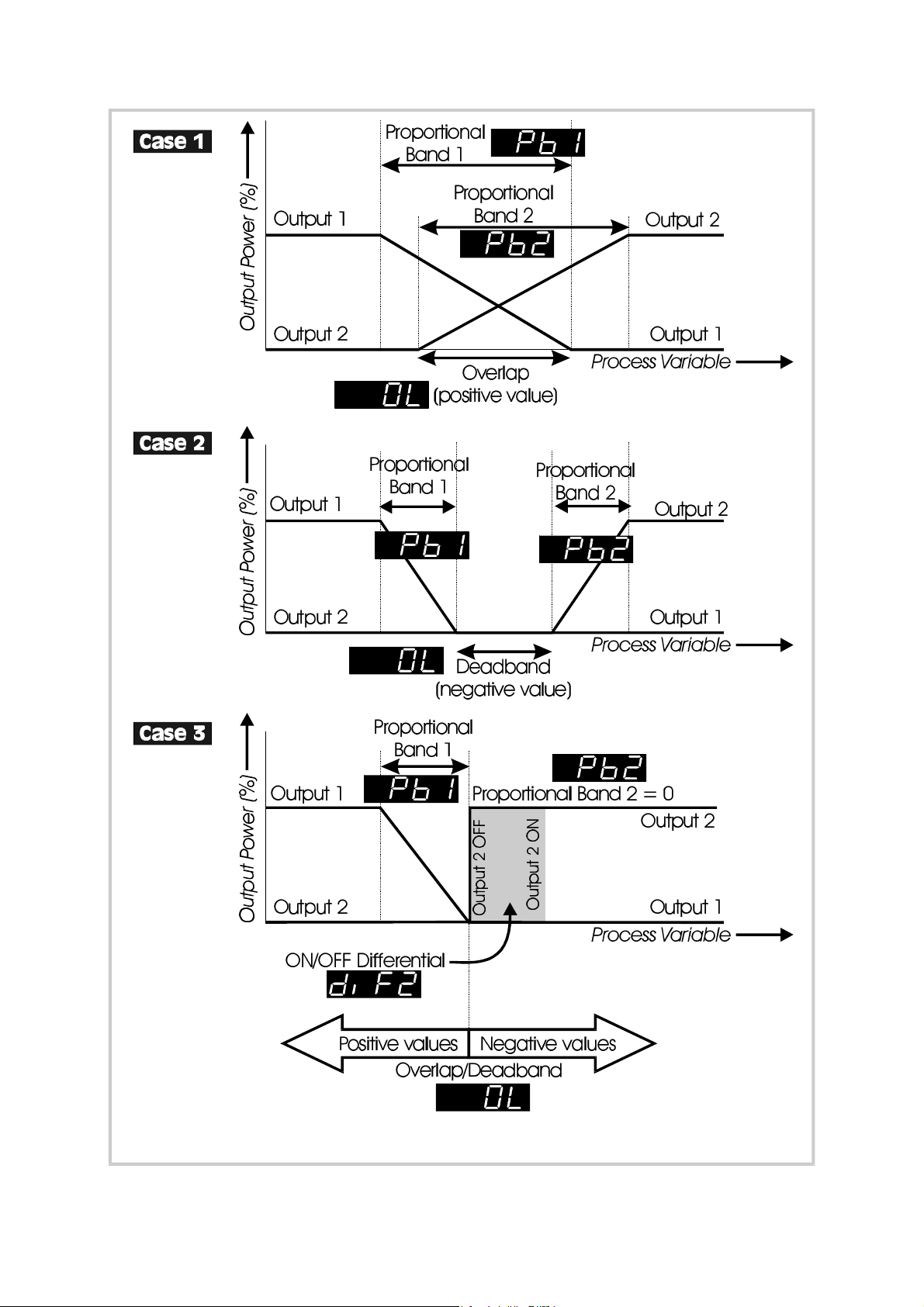
2.2.5 Proportional Band 1
This parameter is the portion of the input span of the Controller over which the
Output 1 power level is proportional to the displayed process variable value. The
function of the Proportional Band 1 is illustrated in Figure 2 -2 .
2.2.6 Proportional Band 2
This parameter is the portion of the input span of the Controller over which the
Output 2 power level is proportional to the displayed process variable value. In
Figure 2-2 , Proportional Band 2 is shown (a) with a non-zero value (Case 1 and
Case 2) - PID control, and (b) with a zero value (Case 3) - ON/OFF control.
2.2.7 Reset ( Integral Time Constant)
This parameter is not applicable if Proportional Band 1 (see Subsection 2.2.5 ) is set
to 0 (ON/OFF control).
2.2.8 Rate ( Derivative Time Constant)
This parameter is not applicable if Proportional Band 1 (see Subsection 2.2.5 ) is set
to 0 (ON/OFF control).
2.2.9 O verlap/Deadband
This defines the portion of the Proportional Band (Proportional Band 1 +
Proportional Band 2) over which both outputs are active (or, in the case of a
deadband, neither output is active). The function of the overlap/deadband is
illustrated in Figure 2 - 2 . This parameter is not applicable if Proportional Band 1 = 0
or if Output 2 is not fitted. Note that, with Output 2 set to ON/OFF control (Figure 2-2
Case 3), the Overlap/Deadband parameter has the effect of moving the ON
Differential band of Output 2 to create an overlap (positive values) or a
deadband (negative values). When Overlap/Deadband = 0, the “Output 2 OFF”
edge of the Output 2 ON/OFF Differential band coincides with the point at which
Output 1 reaches 0%.
2-5 O054-2
Page 17
59125
Figure 2-2 Proportional Band and Deadband/Overlap
O054-2 2-6
Page 18

59125
2.2.10 Bias (Manual Reset)
This bias to the output power is expressed as a percentage of output power. This
parameter is not applicable if Proportional Band 1 = 0.
2.2.11 ON/OFF Differential
This is a switching differential used when one or both outputs have been set to
ON/OFF control (i.e. Proportional Band 1 or Proportional Band 2 or both = 0).
2.2.12 Setpoint High Limit
This is the maximum limit for setpoint adjustment. It should be set to a value which
prevents the setpoint being given a value which will cause damage to the
process being controlled.
2.2.13 Setpoint Low Limit
This is the minimum limit for setpoint adjustment. It should be set to a value which
prevents the setpoint being given a value which will cause damage to the
process being controlled.
2.2.14 Recorder Output Scale Maximum
This parameter defines the value of process variable or setpoint (whichever is
applicable) at which the Recorder Output reaches its maximum value; for
example, for a 0 - 5V Recorder Output, this value corresponds to 5V. The decimal
point position for the Recorder Output is always the same as that for the process
variable input range. This parameter is not applicable if the Recorder Output
option is not fitted.
NOTE: If this parameter is set to a value less than that for the Recorder
Output Scale Minimum (see Subsection 2.2.15 ), the relationship between
the process variable/setpoint value and the Recorder Output is reversed.
2.2.15 Recorder Output Scale Minimum
This parameter defines the value of the process variable or setpoint (whichever is
applicable) at which the Recorder Output reaches its minimum value; for
example, for a 0 - 5V Recorder Output, this value corresponds to 0V. The decimal
point position for the Recorder Output is always the same as that for the process
variable input range. This parameter is not applicable if the Recorder Output
option is not fitted.
NOTE: If this parameter is set to a value greater than that for the Recorder
Output Scale Maximum (see Subsection 2.2.14 ), the relationship between
the process variable value and the Recorder Output is reversed.
2 -7 O054-2
Page 19

59125
2.2.16 Output 1 Power Limit
This parameter is used to limit the power level of Output 1 and may be used to
protect the process being controlled. If no protection is required, this parameter
may be set to 100%. IThis parameter is not applicable if Proportional Band 1 is set
to 0.
2.2.17 Output 1 Cycle Time
The cycle time value required is dependent upon the process being controlled
and the type of output being used for Output 1. For a Relay Output, the cycle
time should be as large as possible (whilst remaining compatible with the process
control requirements) in order to maximise relay life. For an SSR Output, the cycle
time may have a lower value (and thus satisfy the requirements of a fast-changing
process variable e.g. flow or pressure). This parameter is not applicable if
Proportional Band 1 is set to 0 or if Output 1 is a DC linear output..
2.2.18 Output 2 Cycle Time
The cycle time value required is dependent upon the process being controlled
and the type of output being used for Output 2. For a Relay Output, the cycle
time should be as large as possible (whilst remaining compatible with the process
control requirements) in order to maximise relay life. For an SSR Output, the cycle
time may have a lower value (and thus satisfy the requirements of a fast-changing
process variable e.g. flow or pressure). This parameter is not applicable if
Proportional Band 1 or Proportional Band 2 is set to 0 or if Output 2 is a DC linear
output.
2.2.19 Process High Alarm 1 Value
This parameter, applicable only when Alarm 1 is selected to be a Process High
alarm, defines the process variable value at or above which Alarm 1 will be
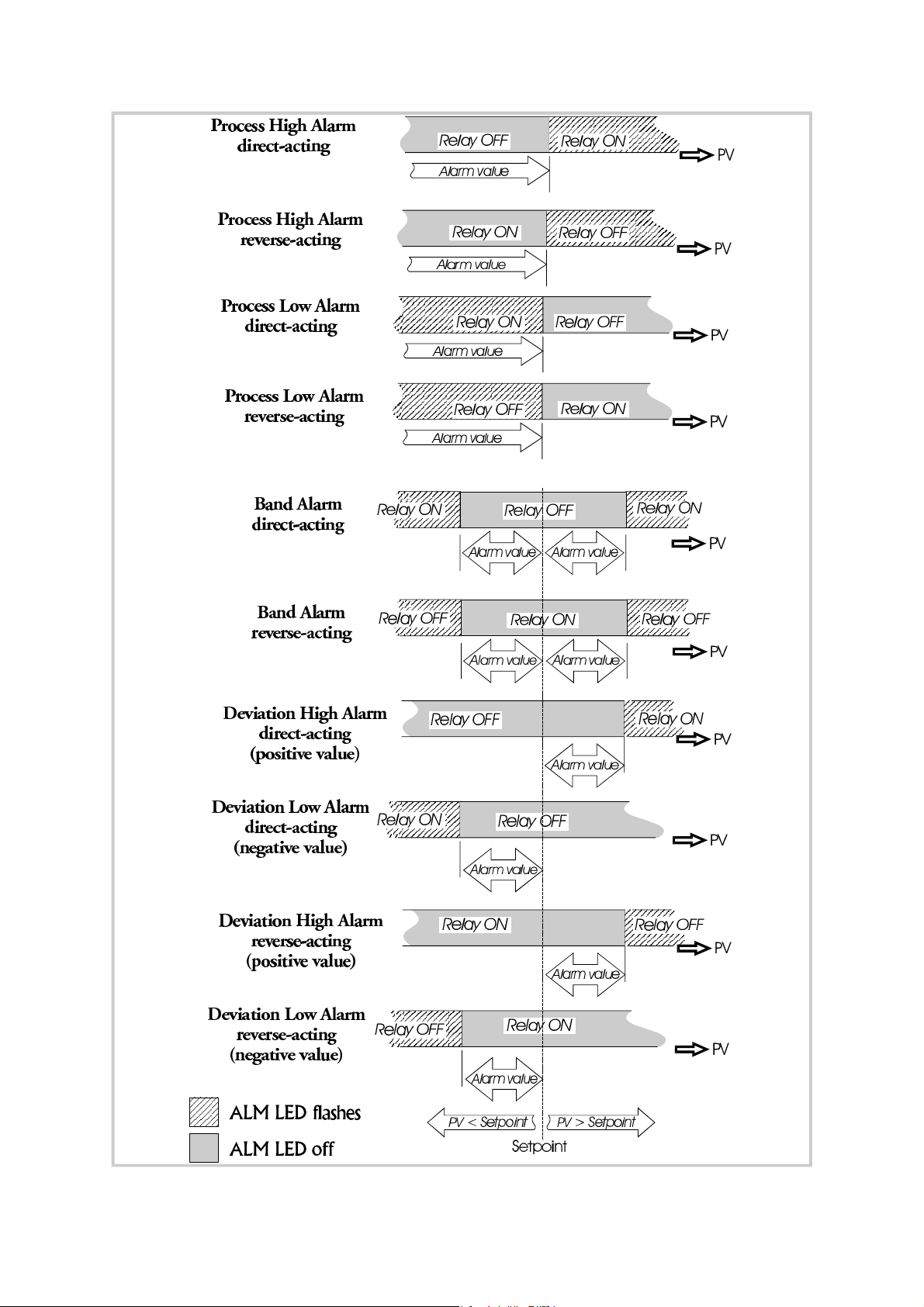
active. The operation of a process high alarm is illustrated in Figure 2-3.
2.2.20 Process Low Alarm 1 Value
This parameter, applicable only when Alarm 1 is selected to be a Process Low
alarm, defines the process variable value at or below which Alarm 1 will be
active. The operation of a process low alarm is illustrated in Figure 2-3.
2.2.21 Band Alarm 1 Value
This parameter, applicable only if Alarm 1 is selected to be a Band Alarm, defines
a band of process variable values, centred on the setpoint value. If the process
variable value is outside this band, the alarm will be active. The operation of a
band alarm is illustrated in Figure 2-3.
O054-2 2-8
Page 20
59125
Figure 2-3 Alarm Operation
2-9 O054-2
Page 21

59125
2.2.22 Deviation (High/Low) Alarm 1 Value
This parameter, applicable only if Alarm 1 is selected to be a Deviation High/Low
Alarm, defines a value above (positive value - Deviation High alarm) or below
(negative value - Deviation Low alarm) the setpoint; if the process variable
deviates from the setpoint by a margin greater than that defined by this
parameter, Alarm 1 goes active. The operation of Deviation Alarms is illustrated in
Figure 2-3.
2.2.23 Process High Alarm 2 Value
This parameter, applicable only when Alarm 2 is selected to be a Process High
alarm, defines the process variable value at or above which Alarm 2 will be
active. The operation of a process high alarm is illustrated in Figure 2-3.
2.2.24 Process Low Alarm 2 Value
This parameter, applicable only when Alarm 2 is selected to be a Process Low
alarm, defines the process variable value at or below which Alarm 2 will be
active. The operation of a process low alarm is illustrated in Figure 2-3.
2.2.25 Band Alarm 2 Value
This parameter, applicable only if Alarm 2 is selected to be a Band Alarm, defines
a band of process variable values, centred on the setpoint value. If the process
variable value is outside this band, the alarm will be active. The operation of a
band alarm is illustrated in Figure 2-3.
2.2.26 Deviation (High/Low) Alarm 2 Value
This parameter, applicable only if Alarm 2 is selected to be a Deviation High/Low
Alarm, defines a value above (positive value - Deviation High alarm) or below
(negative value - Deviation Low alarm) the setpoint; if the process variable
deviates from the setpoint by a margin greater than that defined by this
parameter, Alarm 2 goes active. The operation of Deviation Alarms is illustrated in
Figure 2-3.
2.2.27 Loop Alarm Enable
This parameter is the means by which the user can enable or disable the Loop
Alarm. The Loop Alarm is a special alarm which detects faults in the control
feedback loop by continuously monitoring process variable response to the
control output(s).
The Loop Alarm facility, when enabled, repeatedly checks the control output(s) for
saturation i.e. either or both outputs being at the maximum or minimum limit. If an
output is found to be in saturation, the Loop Alarm facility starts a timer; thereafter,
O054-2 2-10
Page 22

59125
if the saturated output has not caused the process variable to be corrected by a
pre-determined amount V after a time T has elapsed, the Loop Alarm goes active.
Subsequently, the Loop Alarm facility repeatedly checks the process variable and
the control output(s). When the process variable starts to change value in the
correct sense or when the saturated output comes out of saturation, the Loop
Alarm is de-activated.
For PID control, the Loop Alarm Time T is always set to twice the value of the Reset
(Integral Time Constant) parameter. For On/Off control, the user-defined value of
the Loop Alarm Time Set Up parameter (see Subsection 2.2.28) is used.
The value of V is dependent upon the input type:
°C ranges: 2°C or 2.0 °C
°F ranges: 3°F or 3.0 °F
Linear ranges: 10 least significant display units
For single output Controllers, the saturation limits are 0% and Out1Max%. For dual
output Controllers, the saturation limits are –100% and Out1Max%.
NOTES
1. Correct operation of the Loop Alarm depends upon reasonably
accurate PID tuning.
2. The Loop Alarm is automatically disabled during Manual Control Mode
and during execution of the Pre-Tune facility. Upon exit from Manual
Control Mode or after completion of the Pre-Tune routine, the Loop Alarm is
automatically re-enabled.
2.2.28 Loop Alarm Time
When full ON/OFF control is selected (i.e. Proportional Band 1 is set to 0) and Loop
Alarm is enabled, this parameter determines the duration of the saturation
condition after which the Loop Alarm will be activated. This parameter is omitted
from the Set Up display sequence if ON/OFF control is not selected or Loop Alarm
is disabled.
2.2.29 Scale Range Decimal
Value Decimal Point Position
Point
0 xxxx
This parameter, applicable only if a linear
input is fitted, defines the position of the
decimal point in values of the process
variable, setpoint, alarm levels and
recorder outputs as shown on the right.
2 -11 O054-2
1 xxx.x
2 xx.xx
3 x .xxx
Page 23

59125
2.2.30 Scale Range Maximum
This parameter, applicable only if a linear input is fitted, defines the scaled input
value when the process variable input hardware is at its maximum value. This
parameter can be set to a value less than (but not equal to) Scale Range
Minimum, in which case the sense of the input is reversed. Decimal point position
is defined by the Scale Range Decimal Point parameter (see Subsection 2.2.29 ).
2.2.31 Scale Range Minimum
This parameter, applicable only if a linear input is fitted, defines the scaled input
value when the process variable input hardware is at its minimum value. This
parameter can be set to a value greater than (but not equal to) Scale Range
Maximum, in which case the sense of the input is reversed. Decimal point position
is defined by the Scale Range Decimal Point parameter (see Subsection 2.2.29 ).
2.2.32 Auto Pre-Tune Enable/Disable
This parameter determines whether or not the Controller’s Pre-Tune facility is
activated automatically on power-up or not.
2.2.33 Manual Control Enable/Disable
This parameter determines whether operator selection of manual control is
enabled or disabled.
2.2.34 Setpoint Ramp Enable/Disable
This parameter enables/disables use of the setpoint ramping feature at user level.
2.2.35 Setpoint Strategy
This parameter enables the user to select the required Operator Mode setpoint
display strategy - see Subsections 1.2.1 (Single Setpoint operation) and 1.2.2 (Dual
Setpoint operation).
2.2.36 Communications Enable/Disable
This parameter enables/disables Write operations (i.e. the changing of parameter
values/settings) via the RS485 communications link, if the Communications Option
PCB is fitted. Parameters can be interrogated via the link, regardless of the setting
of this parameter.
2.2.37 Lock Value
This parameter defines the four-digit code required to enter Set Up Mode.
O054-2 2-12
Page 24

59125
2.3 OPERATOR MODE DISPLAYS
Once the complete cycle of Set Up Mode parameters has been displayed, the
user may then step through the Operator Mode displays (see Subsection 1.2),
making adjustments where required, before re-starting the Set Up Mode
parameter cycle, as shown in Table 2-1.
2.4 TUNING THE CONTROLLER MANUALLY
2.4.1 Controllers Fitted with Output 1 Only
Before starting to tune the Controller to the load, check that the Setpoint High and
Low Limits (SPhi and SPLo) are set to safe levels - see Subsections 2.2.12 and
2.2.13 .
The following simple technique may be used to determine values for proportional
band (Pb1), derivative time constant (rAtE) and integral time constant (rSEt).
NOTE: This technique is suitable only for processes which are not harmed by
large fluctuations in the process variable. It provides an acceptable basis
from which to start fine tuning for a wide range of processes.
1. Set the setpoint to the normal operating process value (or to a lower
value if overshoot beyond this value is likely to cause damage).
2. Select ON/OFF Control (i.e. set Pb1 = 0).
3. Switch on the process. The process variable will oscillate about the
setpoint. Note (a) The peak-to-peak variation (P) of the first cycle i.e. the
difference between the highest value of the first overshoot and the lowest
value of the first undershoot, and (b)tThe cycle time (T) of this oscillation in
minutes (see Figure 2-4)
4. The control parameters should then be set as follows:
=
= T minutes
P
x 100
ScaleRange
T
=
minutes
6
NOTE: After setting up the parameters, set the Controller to Operator Mode
(see Subsection 2.6) to prevent unauthorised adjustment to the values.
2 -13 O054-2
Page 25

59125
Figure 2 -4 Manual Tuning Parameters - Output 1 only
2.4.2 Controllers Fitted with Output 1 and Output 2
Before starting to tune the Controller to the load, check that the Setpoint High and
Low Limits (SPhi and SPLo) are set to safe levels - see Subsections 2.2.12 and
2.2.13 .
The following simple technique may be used to determine values for proportional
band (Pb1), derivative time constant (rAtE) and integral time constant (rSEt).
NOTE: This technique is suitable only for processes which are not harmed by
large fluctuations in the process variable. It provides an acceptable basis
from which to start fine tuning for a wide range of processes.
1. Tune the Controller using Output 1 only as described in Subsection 2.4.1.
2. Set Pb2 to the same value as Pb1 and monitor the operation of the
Controller in dual output mode. If there is a tendency to oscillate as control
passes into the Output 2 proportional band, increase the value of Pb2. If
the process appears to be over-damped in the region of the Output 2
proportional band, decrease the value of Pb2.
3. When values of proportional bands, integral time constant and derivative
time constant have been determined for tuning, if there is a “kick” as
control passes from one output to the other, set OL to a positive value to
introduce some overlap. Adjust the value of OL by trial and error until
satisfied.
2.5 SELF-TUNE AND PRE-TUNE FACILITIES
Once the Controller has been manually tuned, the Self-Tune and Pre-Tune
facilities may be used in Operator Mode to enhance further the response of the
Controller (see Subsections 1.9 and 1.8 respectively).
O054-2 2-14
Page 26

59125
2.6 EXIT FROM SET UP MODE
To leave Set Up Mode, select the initial Operator Mode display (normally process
variable) then depress the Raise and Function keys simultaneously, whereupon
the Controller will return to Operator Mode. NOTE: An automatic return to Operator
mode will be executed if there is no key activity in Set Up Mode for two minutes.
2-15 O054-2
Page 27

59125
3 RS485 SERIAL COMMUNICATIONS
The Controller may be equipped with a two-wire RS485-compatible serial
communications facility, by which means communication may occur between
the Controller and a master device (e.g. a computer or terminal).
3.1 COMMUNICATIONS ENABLE/DISABLE
When Communications are enabled (in Set Up Mode - see Subsection 2.2.36), the
Controller parameters may be adjusted by the master device via the serial
communications link. If communications are disabled, the Controller will not adjust
or change any parameters in response to commands received from the master
device and will send a negative acknowledgement in response to such
commands. Whether communications are enabled or disabled, the Controller will
return the requested information in response to a Type 2 Interrogation message
(see Subsection 3.2.5 ) from the master device.
3.2 PHYSICAL REQUIREMENTS
3.2.1 Character Transmission
Data format is fixed to be even parity, seven data bits and one stop bit. The Baud
rate may be selected to be 1200, 2400, 4800 (default) or 9600 Baud.
3.2.2 Line Turn-Round
The communications link is operated as a multi-drop half duplex system. When a
device is transmitting, it drives the transmission lines to the appropriate levels;
when it is not transmitting, its outputs are set to a high impedance in order that
another device can transmit. It is important that a transmitter releases the
transmission lines before another device starts transmission. This imposes the
following restraints on the master device:
(a) The transmitter must release the transmission lines within 6ms of
the end of the last character of a message being transmitted. Note
that delays due to buffers such as those used in universal
asynchronous receivers/trans-mitters (UARTs) within the master device
must be taken into account.
(b) The transmitter must not start transmission until 6ms has elapsed
since the reception of the last character of a message.
All Controllers in this range having an RS485 communications facility adhere to this
standard; thus, provided that the master device conforms similarly to the
standard, there should be no line contention problems.
O054-3 3-1
Page 28

59125
3.2.3 Communications Protocol
The protocol assumes half duplex communications. All communication is initiated
by the master device. The master sends a command or query to the addressed
slave and the slave replies with an acknowledgement of the command or the
reply to the query. All messages, in either direction, comprise:
(a) A Start of Message character
(b) One or two address characters (uniquely defining the slave)
(c) A parameter/data character string
(d) An End of Message character
Messages from the master device may be one of four types:
Type 1: L {N} ? ? *
Type 2: L {N} {P} {C} *
Type 3: L {N} {P} # {DATA} *
Type 4: L {N} {P} I *
Table 3 -1 {DATA} Element - Sign
and Decimal Point
where all characters are in ASCII code and:
L is the Start of Message
character (Hex 4C)
{N} is the slave Controller
address (in the range 1 -
32); addresses 1 - 9 may be
{DATA} Content Sign/Decimal Point
abcd0 +abcd
abcd1 +abc.d
abcd2 +ab.cd
abcd3 +a.bcd
abcd5 -abcd
abcd6 -abc.d
represented by a single digit
(e.g. 7) or in two-digit form,
the first digit being zero (e.g.
abcd7 -ab.cd
abcd8 -a.bcd
07).
{P} is a character which identifies the parameter to be
interrogated/modified.
{C} is the command (see below)
# indicates that {DATA} is to follow (Hex 23)
{DATA} is a string of numerical data in ASCII code (see Table 3 -1 )
* is the End of Message character (Hex 2A)
No space characters are permitted in messages. Any syntax errors in a received
message will cause the slave controller to issue no reply and await the Start of
Message character.
3-2 O054-3
Page 29

59125
3.2.4 Type 1 Message
L {N} ? ? *
This message is used by the master device to determine whether the addressed
slave Controller is active. The reply from the slave Controller, if it is active, is
L {N} ? A *
An inactive Controller will give no reply.
3.2.5 Type 2 Message
L {N} {P} {C} *
This type of message is used by the master device to interrogate or modify a
parameter in the addressed Controller. {P} identifies the parameter and {C}
represents the command to be executed, which may be one of the following:
+ (Hex 2B) - Increment the value of the parameter defined by {P}
– (Hex 2D) - Decrement the value of the parameter defined by {P}
? (Hex 3F) - Determine the current value of the parameter defined by {P}
The reply from the addressed Controller is of the form:
L {N} {P} {DATA} A *
where {DATA} comprises five ASCII-coded digits whose format is shown in Table
3-1. The data is the value requested in a query message or the new value of the
parameter after modification. If the action requested by the message from the
master device would result in an invalid value for that parameter (either because
the requested new value would be outside the permitted range for that
parameter or because the parameter is not modifiable), the Controller replies with
a negative acknowledgement:
L {N} {P} {DATA} N *
The {DATA} string in the negative acknowledgement reply will be indeterminate. If
the process variable or the deviation is interrogated whilst the process variable is
outside the range of the Controller, the reply is L{N}{P}<??>0A* if the process
variable is over-range, or L{N}{P}<??>5A* if the process variable is
under-range.
Scan Tables
A parameter identifier character “]” in the message from the master device
indicates that a “Scan Table” operation is required. This provides a facility for
O054-3 3-3
Page 30

59125
interrogating the values of a group of parameters and status in a single message
from the master device. The reply to such a command would be in the form:
L {N} ] xx aaaaa bbbbb ccccc ddddd eeeee A *
where xx is the number of data digits to follow; this is 20 for a single-control-output
instrument and 25 for a dual-control-output instrument. The digits are expressed as
shown in Table 3 -1 . For further information, refer to Subsection 3.3.6 .
3.2.6 Type 3 Message
L {N} {P} # {DATA} *
This message type is used by the master device to set a parameter to the value
specified in {DATA}. The command is not implemented immediately by the slave
Controller; the slave will receive this command and will then wait for a Type 4
message (see below). Upon receipt of a Type 3 message, if the {DATA} content
and the specified parameter are valid, the slave Controller reply is of the form:
L {N} {P} {DATA} I *
(where I = Hex 49) indicating that the Controller is ready to implement the
command. If the parameter specified is invalid or is not modifiable or if the
desired value is outside the permitted range for that parameter, the Controller
replies with a negative acknowledgement in the form:
L {N} {P} {DATA} N *
3.2.7 Type 4 Message
L {N} {P} I *
This type of message is sent by the master device to the addressed slave
Controller following a successful Type 3 message transmission and reply to/from
the same slave Controller. Provided that the {DATA} content and the parameter
specified in the preceding Type 3 message are still valid, the slave Controller will
then set the parameter to the desired value and will reply in the form:
L {N} {P} {DATA} A *
where {DATA} is the new value of the parameter. If the new value or parameter
specified is invalid, the slave Controller will give a negative acknowledgement:
L {N} {P} {DATA} N *
where {DATA} is indeterminate. If the immediately-preceding message received
by the slave Controller was not a Type 3 message, the Type 4 message is ignored.
3-4 O054-3
Page 31

59125
3.3 INDIVIDUAL PARAMETERS
The individual parameters and how they may be interrogated/modified are
described below. Unless otherwise stated, the {DATA} element will follow the
standard five-digit format and the decimal point position must be correct for the
new value to be accepted and for modification to occur.
3.3.1 Input Parameters
Parameter Identifier Description
Process Variable
Process Variable Offset
Scale
Range
Max.
Scale
Range
Min.
M Read (Type 2 message) Only; If out of range, {DATA} will
contain <??>0 (over-range) or <??>5 (under-range).
v May be read (Type 2 message) or modified (Type 3/Type 4
message sequence). Modifies actual process variable
value (as measured at the input terminals):
Modified PV value
= Actual PV value + PV offset value
Modified value is limited by Range Maximum and Range
Minimum and is used for display/alarm purposes and for
recorder outputs. Choose this value with care. In effect, it
modifies the Controller’s calibration. Lack of care could
result in the displayed PV value having no meaningful
relationship to the actual PV value.
G Adjustable only on DC inputs. May be read (Type 2
message) or modified (Type 3/Type 4 message sequence).
Decimal point position is as for the input range. If less than
Scale Range Min. Value, sense of input is reversed.
H Adjustable only on DC inputs. May be read (Type 2
message) or modified (Type 3/Type 4 message sequence).
Decimal point position is as for the input range. If greater
than Scale Range Max. Value, sense of input is reversed.
Scale
Range
Decimal
Point
Input Filter Time Constant
O054-3 3-5
Q Adjustable on DC inputs only. May be read (Type 2
message) or modified (Type 3/Type 4 mesage sequence).
Defines the decimal point position:
0 = abcd 1 = abc.d 2 = ab.cd
3 = a.bcd
m May be read or modified using a Type 2 message or a
Type 3/Type 4 message sequence.
Page 32

3.3.2 Output Parameters
Parameter Identifier Description
59125
Power Output value
Output 1 Power Limit
Output 1 Cycle Time
Output 2 Cycle Time
W If Manual Control is not selected, may be read
only (Type 2 message). If Manual Control is
selected, may be read (Type 2 message) or
modified (Type 3/Type 4 message sequence).
B May be read (Type 2 message) or modified (Type
3/Type 4 message sequence). Defines power limit
for Output 1.
N May be read (Type 2 message) or modified (Type
3/Type 4 message sequence). NOTE: Value must
be a power of 2 in the range 0.5 - 512 (i.e. 0.5, 1,
2, 4, 8 etc.). For a Relay Output, cycle time should
be as large as possible (whilst remaining
compatible with the process control requirements)
in order to maximise relay life. For an SSR Output,
the cycle time may have a lower value (and thus
satisfy the requirements of a fast-changing
process variable e.g. flow or pressure).
O May be read (Type 2 message) or modified (Type
3/Type 4 message sequence). NOTE: Value must
be a power of 2 in the range 0.5 - 512 (i.e. 0.5, 1,
2, 4, 8 etc.). For a Relay Output, cycle time should
be as large as possible (whilst remaining
compatible with the process control requirements)
in order to maximise relay life. For an SSR Output,
the cycle time may have a lower value (and thus
satisfy the requirements of a fast-changing
process variable e.g. flow or pressure).
Recorder Output
Scale Max.
[ May be read/modified by a Type 2 message or a
Type 3/Type 4 message sequence. Corresponds to
Input Scale Max. with decimal point position as for
input. If less than Recorder Output Scale Min.
sense of recorder output is reversed.
Recorder Output
Scale Min.
\ May be read/modified by a Type 2 message or a
Type 3/Type 4 message sequence. Corresponds to
Input Scale Min. with decimal point position as for
input. If greater than Recorder Output Scale Max.
sense of recorder output is reversed.
3-6 O054-3
Page 33

59125
3.3.3 Setpoint Parameters
Parameter Identifier Description
Setpoint value
Setpoint Ramp Rate
Setpoint High Limit
Setpoint Low Limit
S May be read (Type 2 message) or modified (Type
3/Type 4 message sequence). Limited by Setpoint High
Limit and Setpoint Low Limit (see below).
^ May be read (Type 2 message) or modified (Type
3/Type 4 message sequence). May be set in the range
1 - 9999 increments/hour or OFF ({DATA} =0000).
Decimal point position is as for input range.
A May be read (Type 2 message) or modified (Type
3/Type 4 message sequence). Defines maximum value
for setpoint (in the range setpoint - Input Range
Maximum). Decimal point position is as for input
range.
T May be read (Type 2 message) or modified (Type
3/Type 4 message sequence). Defines minimum value
for setpoint (in the range Input Range Minimum setpoint). Decimal point position is as for input range.
3.3.4 Alarm Parameters
Parameter Identifier Description
Alarm 1 value C May be read/modified by a Type 2 message or a
Type 3/Type 4 message sequence. Decimal point
position is as for input range.
Alarm 2 value E May be read/modified by a Type 2 message or a
Type 3/Type 4 message sequence. Decimal point
position is as for input range.
For descriptions of the operation of the different alarm types, see Figure 2-3 .
O054-3 3-7
Page 34

3.3.5 Tuning Parameters
Parameter Identifier Description
59125
Rate (Derivative Time Constant)
Reset (Integral Time Constant)
Manual Reset (Bias)
ON/OFF Differential
D May be read/modified using a Type 2 message or a
Type 3/Type 4 message sequence. Defines the
derivative time constant for the control algorithm.
{DATA} is of the form mm.ss where mm = minutes
and ss = seconds. The decimal point position must
specify two decimal places, otherwise modification
will not occur.
I May be read/modified using aType 2 message or a
Type 3/Type 4 message sequence. Defines the
integral time constant for the control algorithm.
{DATA} is of the form mm.ss where mm = minutes
and ss = seconds. The decimal point position must
specify two decimal places, otherwise modification
will not occur.
1
J May be read/modified using a Type 2 message or a
Type 3/Type 4 message sequence. Decimal point
position is as for input range.
F May be read/modified using a Type 2 message or a
Type 3/Type 4 message sequence. Defines the
switching hysteresis for controllers with an ON/OFF
control output. Decimal point position = 1.
Overlap
/Deadband
Proportional Band 1 value
Proportional Band 2 value
K May be read/modified using a Type 2 message or a
Type 3/Type 4 message sequence. May be set to a
positive (overlap) or negative (deadband) value.
Decimal point position = 0.
2
P May be read/modified using a Type 2 message or a
Type 3/Type 4 message sequence. May be set to
0.0 (ON/OFF control) or within the range 0.5% -
999.9% of Output 1 power range. Decimal point
position = 1.
U May be read/modified using a Type 2 message or a
Type 3/Type 4 message sequence. May be set to
0.0 (ON/OFF control) or within the range 0.5% -
999.9% of Output 2 power range. Decimal point
position = 1.
2
3-8 O054-3
Page 35

59125
3.3.6 Status Parameters
Parameter Identifier Description
Controller Status
Arithmetic Deviation
Scan Tables
L Read Only (Type 2 message). Status information is
encoded in four digits as the decimal representation of a
binary number; each bit in the binary number has a
particular significance (see Figure 3-1 ).
V Read Only (Type 2 message). The difference between the
process variable value and the Limit Setpoint value.
] Read Only (Type 2 message). Response:
L{N}xxaaaaabbbbbcccccdddddeeeeeA*
where:
xx = Number of data digits in {DATA}
element (20 for single control output,
25 for dual control outputs)
aaaaa = Current setpoint value
bbbbb = Current process variable value
ccccc = Current value of Output 1 Power
(0 - 100%)
ddddd = Current value of Output 2 Power
(0 - 100%) - if applicable.
eeeee = Controller Status (see Figure 3-1)
3.3.7 Controller Commands
Parameter Identifier Description
Controller Commands
Z Implemented by Type 3/Type 4 message sequence only.
In the Type 3 message, {DATA} must be one of eight
five-digit numbers:
00010 Activate Manual Control
00020 Activate Automatic Control
00030 Activate Self-Tune
00040 De-activate Self-Tune
00050 Request Pre-Tune*
00060 Abort Pre-Tune
00130 Activate Loop Alarm
00140 De-activate Loop Alarm
The response from the Controller also contains the same
{DATA} content, as does the response to the Type 4
message.
O054-3 3-9
Page 36

59125
Figure 3-1 Controller Status Byte
3.4 ERROR RESPONSE
The circumstances under which a message received from the master device is
ignored are:
Parity error detected
Syntax error detected
Timeout elapsed
Receipt of a Type 4 message without a preceding Type 3 command
message.
Negative acknowledgements will be returned if, in spite of the received message
being notionally correct, the Controller cannot supply the requested information
or perform the requested operation. The {DATA} element of a negative
acknowledgement will be indeterminate.
3-10 O054-3
Page 37

59125
Alphabetic Index - Volume 1
A
Alarm 1 Value
Band Alarm 2-3
Deviation Alarm 2-3
Process High Alarm 2-3
Process Low Alarm 2-3
Alarm 2 Value
Band alarm 2-3
Deviation alarm 2-3
Process High alarm 2-3
Process Low alarm 2-3
Alarm Operation
Illustration of2-9
Alarm Status
Display of 1-3
Displaying (Set Up mode)2-4
Auto Pre-Tune Enable/Disable 2-12
H
Hardware Definition Code
Explanation of 1-7
Viewing 1-7
I
Input Filter Time Constant 2-2
Input Over-Range
Indication of 1-4
Input Scale Range
Decimal point position 2-4
Input Scale Range Maximum 2-4
Input Scale Range Minimum 2-4
Input Under-Range
Indication of 1-4
Integral Time Constant (Reset) 2-5
B
Band Alarm 1 2-8
Band Alarm 2 2-10
Bias (Manual Reset) 2-7
C
Communications Line Release Time
Maximum Value 3-1
Communications Message
Format 3-2
D
Deadband 2-5
Decimal Point Position
Input scale range 2-4
Derivative Time Constant (Rate) 2-5
Deviation Alarm 1 2-10
Deviation Alarm 2 2-10
Digital Filter Time Constant 2-3
L
Lock Value 2-12
Loop Alarm 2-10
Loop Alarm Enable 2-10
Loop Alarm Time 2-11
M
Manual Control Mode
De-selection of 1-4
Indication of 1-4
Selection of 1-4
Manual Control Selection
Enable/Disable 2-12
Manual Reset (Bias) 2-7
Manual Tuning
Controllers with Output 1 and
Output 2 2-14
Controllers with
Output 1 only 2-13
O056-IDX 1
Page 38

59125
O
ON/OFF Differential 2-7
Output 1 Cycle Time 2-8
Output 1 Power Limit 2-8
Output 2 Cycle Time 2-8
Output Power 1 2-5
Output Power 2 2-5
Overlap 2-5
P
Pre-Tune Facility
Activation of 1-5
Process High Alarm 1 2-8
Process High Alarm 2 2-10
Process Low Alarm 1 2-8
Process Low Alarm 2 2-10
Process Variable Offset 2-2
Proportional Band 1 2-5
Proportional Band 2 2-5
R
Rate (Derivative Time Constant)2-5
Recorder Output Scale Maximum
2-7
Recorder Output
Scale Minimum 2-7
Reset2-5
Reset (Integral Time Constant) 2-5
End of Message
character 3-2
Error response 3-10
Line turn-round time 3-1
Message Types 3-2
Protocol 3-2
Scan Tables command 3-3
Start of Message
character 3-2
Type 2 message 3-3
Type 3 message 3-4
Type 4 message 3-4
Set Up Mode
Entry into 2-1
Exit from 2-15
Lock code 2-4
Set Up Parameters at default
Indication of 2-2
Setpoint
Adjustment of 1-3
Setpoint Display Strategy
Single Setpoint operation1-2
Setpoint High Limit2-7
Setpoint Low Limit 2-7
Setpoint Ramp Rate
Viewing/adjusting 1-3
Setpoint Ramping
Adjusting the
ramping rate 1-3
Enabling/disabling 2-12
Setpoint Strategy 2-12
Dual Setpoint operation 1-3
S
Scale Range Decimal Point 2-11
Scale Range Maximum 2-12
Scale Range Minimum 2-12
Self-Tune Facility
Activation of 1-6
Sensor Break
Indication of 1-4
Serial Communications
Data Format 3-1
Enabling/disabling2-4, 2-12
2 O056-IDX
Page 39

59125
1
-DIN,
4
1
-DIN &
8
1
1 6
-DIN
TEMPERATURE CONTROLLERS
PRODUCT MANUAL
VOLUME 2
INSTALLATION & CONFIGURATION
INSTRUCTIONS
The procedures described in this Volume must be undertaken only
by technically-competent servicing personnel.
Contents - Volume 2
1 INSTALLATION 1-1
1.1 UNPACKING 1-1
1.2 PANEL-MOUNTING 1-1
1.3 CONNECTIONS AND WIRING 1-4
2 INTERNAL LINKS AND SWITCHES 2-1
2.1 REMOVING THE CONTROLLER FROM ITS HOUSING 2-1
2.2 REMOVING/REPLACING THE OUTPUT 2/OUTPUT 3 OPTION PCBs 2-3
2.3 REMOVING/REPLACING THE RS485 COMMUNICATIONS OPTION PCB
OR DUAL SETPOINT OPTION PCB 2-3
2.4 REPLACING THE CONTROLLER IN ITS HOUSING 2-3
2.5 SELECTION OF INPUT TYPE 2-4
2.6 SELECTION OF OUTPUT 1 TYPE 2-5
2.7 OUTPUT 2 TYPE/OUTPUT 3 TYPE 2-5
3 CONFIGURATION MODE 3-1
3.1 ENTRY INTO CONFIGURATION MODE 3-1
S056-V2 (i)
Page 40

59125
3.2 HARDWARE DEFINITION CODE 3-2
3.3 OPTION SELECTION 3-3
3.4 CONFIGURATION MODE PARAMETERS 3-4
3.5 ALARM HYSTERESIS OUTPUTS 3-8
3.6 EXIT FROM CONFIGURATION MODE 3-9
Appendices
A PRODUCT SPECIFICATION A-1
A.1 UNIVERSAL INPUT A-1
A.2 DUAL SETPOINT SELECTION INPUT (OPTION) A-3
A.3 OUTPUT 1 A-4
A.4 OUTPUT 2 A-5
A.5 OUTPUT 3 A-7
A.6 LOOP CONTROL A-8
A.7 ALARM CONTROL A-9
A.8 PERFORMANCE A-9
A.9 ENVIRONMENTAL A-11
A.10 PHYSICAL A-12
(ii) S056-V2
Page 41

59125
1 INSTALLATION
1.1 UNPACKING
1. Remove the Controller from its packing. The Controller is supplied with a
panel gasket and push-fit fixing strap. Retain the packing for future use,
should it be necessary to transport the Controller to a different site or to
return it to the supplier for repair/testing.
2. Examine the delivered items for damage or deficiencies. If any is found,
notify the carrier immediately.
1.2 PANEL-MOUNTING
The panel on which the Controller is to be mounted must be rigid and may be up
to 6.0mm (0.25 inches) thick. The cut-out required for a single Controller is as
shown in Figure 1 -1 .
Figure 1-1 Cut-out Dimensions
Several controllers may be installed in a single cut-out, side-by-side. For n
Controllers mounted side-by-side, the width of the cut-out would be:
1
-DIN &
16
1
-DIN: (96n - 4) millimetres or (7.56n - 0.16) inches
4
1
-DIN: (48n - 4) millimetres or (3.78n - 0.16) inches
8
The main dimensions of the Controller are shown in Figure 1 -2 .
O054-1 1-1
Page 42

59125
Figure 1-2 Main Dimensions
The procedure to panel-mount the Controller is shown in Figure 1 -3 .
CAUTION: Do not remove the panel gasket, as this may result in inadequate
clamping of the instrument in the panel.
NOTE: The mounting clamp tongues may engage the ratchets either on the
sides of the Controller housing or on the top/bottom faces of the Controller
housing. Therefore, when installing several Controllers side-by-side in one
cut-out, use the ratchets on the top/bottom faces.
1-2 O054-1
Page 43

59125
Figure 1-3 Panel-Mounting the Limit Controller
Once the Controller is installed in its mounting panel, it may be subsequently
removed from its housing, if necessary, as described in Subsection 2.1.
O054-1 1-3
Page 44

1.3 CONNECTIONS AND WIRING
59125
The rear terminal connections are illustrated in Figure 1-4 (
controllers) and Figure 1-5 (
1
-DIN controllers).
16
1
-DIN and
4
1
-DIN
8
Figure 1 -4 Rear Terminals (
1
-DIN &
4
1
-DIN Controllers)
8
1 -4 O054-1
Page 45

59125
Figure 1 -5 Rear Terminals (
1
-DIN Controllers)
16
O054-1 1-5
Page 46

59125
1.3.1 Mains (Line) Input
The Controller will operate on 96 - 264V AC 50/60Hz mains (line) supply. The power
consumption is approximately 4 VA.
CAUTION: This equipment is designed for installation in an enclosure which
provides adequate protection against electric shock. Local regulations
regarding electrical installation should be rigidly observed. Consideration
should be given to prevention of access to the power terminations by
unauthorised personnel. Power should be connected via a two-pole
isolating switch (preferably situated near the equipment) and a 1A fuse, as
shown in Figures 1 -4 and 1 -5 .
If the Controller has relay outputs in which the contacts are to carry mains
(line) voltage, it is recommended that the relay contact mains (line) supply
should be switched and fused in a similar manner but should be separate
from the Controller mains (line) supply.
1.3.2 24V (Nominal) AC/DC Supply
The supply connections for the 24V AC/DC option of the Controller are as shown in
Figures 1-4 and 1 -5 . Power should be connected via a two-pole isolating switch
and a 315mA slow-blow (anti-surge Type T) fuse. With the 24V AC/DC supply option
fitted, these terminals will accept the following supply voltage ranges:
24V (nominal) AC 50/60Hz - 20 - 50V
24V (nominal) DC - 22 - 65V
1.3.3 Thermocouple Input
The correct type of thermocouple extension leadwire or compensating cable
must be used for the entire distance between the Controller and the
thermocouple, ensuring that the correct polarity is observed throughout. Joints in
the cable should be avoided, if possible. The Controller’s CJC facility must be
enabled (normal conditions) for this input (see Page 3-8 ).
NOTE: Do not run thermocouple cables adjacent to power-carrying
conductors. If the wiring is run in a conduit, use a separate conduit for the
thermocouple wiring. If the thermocouple is grounded, this must be done at
one point only. If the thermocouple extension lead is shielded, the shield
must be grounded at one point only.
1.3.4 RTD Inputs
The compensating lead should be connected to Terminal 4 (
Terminal 3 (
1
(
-DIN controllers) or Terminals 2 and 3 (
16
1
-DIN and
4
1
-DIN controllers). For two-wire RTD inputs, Terminals 4 & 5
8
1
-DIN and
4
1
-DIN controllers) should be
8
linked. The extension leads should be of copper and the resistance of the wires
1 - 6 O054-1
1
-DIN controllers) or
16
Page 47

59125
connecting the resistance element should not exceed 5 ohms per lead (the leads
should be of equal resistance).
1.3.5 Linear Inputs
For linear mA input ranges, connection is made to Terminals 4 and 6 (
controllers) or Terminals 4 and 1 (
1
-DIN &
4
1
-DIN controllers) in the polarity shown in
8
16
1
-DIN
Figures 1-4 and 1-5. For linear mV and V ranges, connection is made to Terminals
4 and 5 (
1
-DIN controllers) or Terminals 3 and 2 (
16
1
-DIN &
4
1
-DIN controllers) in the
8
polarity shown in Figures 1-4 and 1-5. For details of the linear input ranges
available, refer to Appendix A.
1.3.6 Dual Setpoint Selection Input
With the Dual Setpoint option fitted, Terminals 11 and 12 (
Terminals 16 and 17 (
1
-DIN &
4
1
-DIN controllers) are used for external selection of
8
the active setpoint. These terminals may be connected to (a) the voltage-free
contacts of a switch or relay, or (b) a TTL-compatible voltage. Setpoint selection is
as follows:
Voltage-Free: Contacts open - Setpoint 1 selected
Contacts closed - Setpoint 2 selected
TTL-compatible: >2.0V - Setpoint 1 selected
<0.8V - Setpoint 2 selected
1
-DIN controllers) or
16
NOTE: The Dual Setpoint option and the RS485 Serial Communications
option are mutually exclusive.
1.3.7 Relay Outputs
The contacts are rated at 2A resistive at 120/240V AC.
1.3.8 SSR Drive Outputs
These outputs produce a time-proportioned non-isolated DC signal (0 - 4.2V
nominal into 1kΩ minimum).
1.3.9 Solid State Outputs
These outputs provide up to 1A AC drive with a longer lifetime than an
electromechanical relay. For further details, refer to Appendix A.
1.3.10 DC Outputs
See Appendix A.
O054-1 1-7
Page 48

59125
1.3.11 RS485 Serial Communications Link
The cable used should be suitable for data transfer at the selected rate (1200,
2400, 4800 or 9600 Baud) over the required distance. Transmitters/receivers
conform to the recommendations in the EIA Standard RS485.
The “A” terminal on the Controller should be connected to the “A” terminal on the
master device; the “B” terminal on the Controller should be connected to the “B”
terminal on the master device. Where several Controllers are connected to one
master port, the master port transceiver in the active state should be capable of
driving a load of 12k Ω per Controller; the master port transceiver in the passive
state must have pull-up/pull-down resistors of sufficiently low impedance to ensure
that it remains in the quiescent state whilst supplying up to
Controller transceivers in the high impedance state.
NOTE: The RS485 Serial Communications option and the Dual
Setpoint option are mutually exclusive.
100µA each to the
±
1-8 O054-1
Page 49

59125
2 INTERNAL LINKS AND SWITCHES
NOTE: The operations described in this Section should be performed only by
personnel trained and authorised to do so.
2.1 REMOVING THE CONTROLLER FROM ITS HOUSING
CAUTION: Before removing the Controller from its housing, ensure that all
power has been removed from the rear terminals.
To withdraw the Controller from its housing, simply grip the side edges of the front
panel (there is a finger grip on each edge) and pull the Controller forwards. This
will release the Controller from its rear connectors in the housing and will give
access to the Controller PCBs. Take note of the orientation of the Controller for
subsequent replacement into the housing.The positions of the PCBs in the
Controller are shown in Figure 2-1.
Figure 2-1 PCB Positions
S054-2 2-1
Page 50

59125
Figure 2-2 Removing the Output 2/Output 3 Option PCBs
2-2 S054-2
Page 51

59125
2.2 REMOVING/ REPLACING THE OUTPUT 2/OUTPUT 3
OPTION PCBs
With the Controller removed from its housing:
1. Gently push the rear ends of the CPU PCB and Power Supply PCB apart
slightly, until the two tongues on each of the Output 2/Output 3 Option PCBs
become dis-engaged - see Figure 2-2B; The Output 2 Option PCB tongues
engage in holes in the Power Supply PCB and the Output 3 Option PCB
tongues engage in holes on the CPU PCB.
2. Carefully pull the required Option PCB (Output 2 or Output 3) from its
connector (Output 2 Option PCB is connected to the CPU PCB and Output 3
Option PCB is connected to the Power Supply PCB) - see Figure 2-2C. Note
the orientation of the PCB in preparation for its replacement.
Adjustments may now be made to the link jumpers on the CPU PCB, the Output
2/Output 3 Option PCBs (if DC output) and (on
1
-DIN Controllers, if fitted) the DC
16
Output 1 PCB. The replacement procedure is a simple reversal of the removal
procedure.
2.3 REMOVING/REPLACING THE RS485
COMMUNICATIONS OPTION PCB OR DUAL SETPOINT
OPTION PCB
This Option PCB is mounted on the inner surface of the Power Supply PCB and can
be removed when the Controller is removed from its housing (see Subsection 2.1 ).
Figure 2 -3 illustrates the removal/replacement procedure. It is not necessary to
remove the Output 2/Output 3 Option PCBs to perform this procedure.
2.4 REPLACING THE CONTROLLER IN ITS HOUSING
To replace the Controller, simply align the CPU PCB and Power Supply PCB with
their guides and connectors in the housing and slowly but firmly push the
Controller into position.
CAUTION: Ensure that the instrument is correctly orientated. A stop will
operate if an attempt is made to insert the instrument in the wrong
orientation (e.g. upside-down). This stop must not be over-ridden.
S054-2 2-3
Page 52

59125
Figure 2-3 Removing the RS485 Communications Option PCB
or the Dual Setpoint Option PCB
2.5 SELECTION OF INPUT TYPE
2.5.1
The selection of input type is
accomplished on link jumpers on the
CPU PCB. The CPU PCB may be either
of two forms: (a) for a relay or SSR
Output 1 (see Figure 2-4) or for a DC
Output 1 (see Figure 2-5). Input type
selection is as shown on the right.
2.5.2
1
-DIN Controllers
16
1
-DIN and
4
1
-DIN
8
Controllers
The selection of input type is
accomplished on link jumpers on the
CPU PCB (see Figure 2-6). Input type
selection is as shown on the right.
Input Type Link Jumpers Fitted
RTD or DC (mV) None (Parked)
Thermocouple LJ3
DC (mA) LJ2
DC (V) LJ1
Input Type Link Jumpers Fitted
RTD or DC (mV) None (Parked)
Thermocouple LJ3
DC (mA) LJ2
DC (V) LJ1
2 -4 S054-2
Page 53

59125
2.6 SELECTION OF OUTPUT 1 TYPE
2.6.1
1
-DIN Controllers
16
The required type of Output 1 is
selected by Link Jumpers LJ4, LJ5,
LJ6 and LJ7 on the Relay/SSR Output
1 CPU PCB (see Figure 2-4) or, on the
DC Output 1 CPU PCB, Link Jumpers
LJ8 and LJ9 (see Figure 2 -5 ). Output
type selection is as shown on the
right.
2.6.2
1
-DIN and
4
1
-DIN
8
Controllers
The required type of Output 1 is
selected by Link Jumpers LJ4, LJ5,
LJ6, LJ7, LJ8 and LJ9 on the PSU PCB
(see Figure 2 -7 ). Output type
selection is as shown on the right.
Output 1 Type Link Jumpers Fitted
Relay or Solid State LJ5 & LJ6
SSR Drive LJ4 & LJ7
DC (0 - 10V) LJ8
DC (0 - 20mA) LJ9
DC (0 - 5V) LJ8
DC (4 - 20mA) LJ9
Output 1 Type Link Jumpers Fitted
Relay or Solid State LJ5 & LJ6
SSR Drive LJ4 & LJ7
DC (0 - 10V) LJ8
DC (0 - 20mA) LJ9
DC (0 - 5V) LJ8
DC (4 - 20mA) LJ9
2.7 OUTPUT 2 TYPE/ OUTPUT 3 TYPE
The type of output for Output 2 and Output 3 is determined by the Option PCB
fitted in the appropriate position (see Figure 2 -1 ). There are four types of option
PCB which may be used for Output 2 and Output 3:
1. Relay Output Option PCB (no link jumpers)
2. Solid State Output Option PCB (no link jumpers)
3. SSR Output Option PCB (no link jumpers)
4. DC Output Option PCB (link jumpers as shown in Figure 2-8)
In the case of the DC Output Option
PCB being fitted, DC output range is
selected using link jumpers LJ8 and
LJ9, as shown on the right.
DC Output Range Link Jumpers Fitted
DC (0 - 10V) LJ8
DC (0 - 20mA) LJ9
DC (0 - 5V) LJ8
DC (4 - 20mA) LJ9
S054-2 2-5
Page 54

59125
Figure 2-4 CPU PCB (Relay/SSR Drive/Solid State Output 1) -
Figure 2 -5 CPU PCB (DC Output 1) -
1
-DIN Controllers
16
1
-DIN Controllers
16
2 -6 S054-2
Page 55

59125
Figure 2 -6 CPU PCB -
1
-DIN &
4
1
-DIN Controllers
8
Figure 2 -7 PSU PCB -
1
-DIN &
4
1
-DIN Controllers
8
S054-2 2-7
Page 56

59125
Figure 2 -8 DC Output Option PCB PCB (Output 2/Output 3)
2 -8 S054-2
Page 57

59125
3 CONFIGURATION MODE
3.1 ENTRY INTO CONFIGURATION MODE
See Figure 3 -1 .
Figure 3 -1 Entry into Configuration Mode
NOTE: Changes to the value/setting of certain Configuration Mode
parameters (e.g. input range, output use and type) will cause the Set Up
Mode parameters to be automatically set to their default values the next
time Set Up Mode is entered (see also Volume 1, beginning of Section 2 ).
S054-3 3-1
Page 58

3.2 H ARDWARE DEFINITION CODE
This parameter is a special facility in Configuration Mode, which is used to
represent the hardware fitted (input type, Output 1 type, Output 2 type and
Output 3 type); this must be compatible with the hardware actually fitted. For
access to, and adjustment of, the Hardware Definition Code, see Figure 3-2.
59125
Figure 3-2 Hardware Definition Code - Access and Adjustment
3-2 S054-3
Page 59

59125
Table 3 -1 Hardware Definition Code - Input/Output Type Selection
Value 0 1 2 3 4 5 7 8
Input RTD/
Linear
Thermocouple
Linear
DC mA
Linear
DC V
DC mV
Output
1
Output
2/3
Not
fitted
Relay SSR
Drive
Relay SSR
Drive
DC
0 - 10VDC0 - 20mADC0 - 5VDC4 - 20mA
DC
0 - 10VDC0 - 2-mADC0 - 5VDC4 - 20mA
Solid
State
Solid
State
NOTES: 1. If Output 2 is set to be a relay/SSR drive/solid state
output, it may be a control output (COOL) or an
alarm output; if it is set to be a DC output, it can only
be a control output (COOL).
2. If Output 3 is set to be a relay/SSR drive/solid state
output, it can only be an alarm output; if it is set to
be a DC output, it can only be a recorder (i.e.
re-transmitted process variable or setpoint) output.
The maximum setting available for this code is 4888. For example, the code for a
thermocouple input, DC 4 - 20mA primary output (Output 1) and relay Output 3
would be 2701.
NOTE: It is essential that this code is changed promptly whenever there is a
change to the Controller’s hardware configuration (change of input/output
type, alarm/recorder output added/removed etc.). The Controller software
depends upon this code to ensure that the Controller operates correctly.
This code may be viewed as a Read Only display in Operator Mode (see Volume
1, Subsection 1.10).
3.3 OPTION SELECTION
This indicates the option fitted (Communications Option, Dual Setpoint Option no
option at all). It is accessed whilst the Hardware Definition Code is displayed (see
Figure 3-3 ).
S054-3 3-3
Page 60

59125
Figure 3 -3 Option Selection
3.4 CONFIGURATION MODE PARAMETERS
Parameter Identifier Description
Input Range
Output 1 Action
Alarm 1 Type
A four-digit code (see Appendix A). Default settings:
Thermocouple - 1419 (Type J, 0 - 761 °C)
RTD/Linear mV - 7220 (RTD Pt100 0 - 800°C)
Linear mA - 3414 (4 - 20mA)
Linear V - 4446 (0 - 10V)
Reverse-acting
Direct-acting
Process High Alarm
Process Low Alarm
Deviation Alarm
Band Alarm
No alarm
3-4 S054-3
Page 61

59125
Parameter Identifier Description
Alarm 2 Type
Alarm Inhibit
Process High Alarm
Process Low Alarm (default)
Deviation Alarm
Band Alarm
No alarm
No alarms inhibited
Alarm 1 inhibited
Alarm 2 inhibited
Both Alarm 1 & Alarm 2 inhibited
S054-3 3-5
Page 62

Parameter Identifier Description
59125
Output 2 Usage
Output 2 secondary control (COOL) output
Alarm 2 hardware output, direct-acting. Available only if relay/SSR drive/solid state output.
Alarm 2 hardware output, reverse-acting. Available only if relay, SSR drive or solid state output.
Direct-acting output for Logical OR of Alarm 1
and Alarm 2. Available only if relay, SSR drive,
or solid state output.
Reverse-acting output for Logical OR of Alarm 1
and Alarm 2. Available only if relay, SSR drive,
or solid state output.
Direct-acting output for Logical AND of Alarm 1
and Alarm 2. Available only if relay, SSR drive,
or solid state output.
Reverse-acting output for Logical AND of Alarm
1 and Alarm 2. Available only if relay, SSR drive,
or solid state output.
Loop Alarm output, direct-acting. Available only
if relay, SSR drive or solid state output.
Loop Alarm output, reverse-acting. Available
only if relay, SSR drive or solid state output.
Alarm Hysteresis output, direct-acting. Available
only if relay, SSR drive or solid state output.
Alarm Hysteresis output, reverse-acting.
Available only if relay, SSR drive or solid state
output.
Example of Logical Combination of Alarms - Logical OR of Alarm 1 & Alarm 2
Direct-acting Reverse-acting
AL1 OFF, AL2 OFF: Relay de-energised AL1 OFF, AL2 OFF: Relay energised
AL1 ON, AL2 OFF: Relay energised AL1 ON, AL2 OFF: Relay de-energised
AL1 OFF, AL2 ON: Relay energised AL1 OFF, AL2 ON: Relay de-energised
AL1 ON, AL2 ON: Relay energised AL1 ON, AL2 ON: Relay de-energised
3-6 S054-3
Page 63

59125
Parameter Identifier Description
Output 3 Usage
Alarm 1 hardware output, direct-acting. Available only if relay/SSR drive/solid state output.
Alarm 1 hardware output, reverse-acting. Available only if relay, SSR drive or solid state output.
Direct-acting output for Logical OR of Alarm 1
and Alarm 2. Available only if relay, SSR drive,
or solid state output.
Reverse-acting output for Logical OR of Alarm 1
and Alarm 2. Available only if relay, SSR drive,
or solid state output.
Direct-acting output for Logical AND of Alarm 1
and Alarm 2. Available only if relay, SSR drive,
or solid state output.
Reverse-acting output for Logical AND of Alarm
1 and Alarm 2. Available only if relay, SSR drive,
or solid state output.
Loop Alarm output, direct-acting. Available only
if relay, SSR drive or solid state output.
Loop Alarm output, reverse-acting. Available
only if relay, SSR drive or solid state output.
Alarm Hysteresis output, direct-acting. Available
only if relay, SSR drive or solid state output.
Alarm Hysteresis output, reverse-acting.
Available only if relay, SSR drive or solid state
output.
Recorder Output - Setpoint (DC output only)
Recorder Output - Process Variable
(DC Output only)
Example of Logical Combination of Alarms - Logical AND of Alarm 1 & Alarm 2
Direct-acting Reverse-acting
AL1 OFF, AL2 OFF: Relay de-energised AL1 OFF, AL2 OFF: Relay energised
AL1 ON, AL2 OFF: Relay de-energised AL1 ON, AL2 OFF: Relay energised
AL1 OFF, AL2 ON: Relay de-energised AL1 OFF, AL2 ON: Relay energised
AL1 ON, AL2 ON: Relay energised AL1 ON, AL2 ON: Relay de-energised
S054-3 3-7
Page 64

Parameter Identifier Description
59125
Comms. Baud
Selectable: 1200, 2400, 4800, 9600 Baud
Rate
Comms. Address Unique address assigned to the controller;
in the range 1 - 32.
Cold Junction
Enabled (default)
Compensation
Enable/Disable*
Disabled
Lock Code Read Only display of current four-digit Set Up
Mode Lock Code.
3.5 ALARM HYSTERESIS OUTPUTS
An alarm hysteresis output is active only when both alarms are active; it becomes
subsequently inactive only when both alarms become inactive. Thus, the status of
the Alarm Hysteresis output when one alarm is active and the other is inactive
depends upon the alarm status immediately prior to that alarm being activated;
thus, with two process high alarms:
3 -8 S054-3
Page 65

59125
3.6 EXIT FROM CONFIGURATION MODE
NOTE: An automatic exit to Operator
Mode will be made if, in Configuration
Mode, there is no front panel key
activity for two minutes.
The exit is made via the power-up self-test
routines which include a lamp test.
S054-3 3-9
Page 66

A PRODUCT SPECIFICATION
A.1 UNIVERSAL INPUT
General
Maximum per Controller: One
Input Sample Rate: Four samples/second
Digital Input Filter: Time constant selectable from front panel -
0.0 (i.e. OFF), 0.5 to 100.0 seconds in
0.5-second increments.
Input Resolution: 14 bits approximately; always four times
better than display resolution.
59125
Input Impedance: Greater than 100M Ω resistive (except for
DC mA and V inputs).
Isolation: Universal input isolated from all outputs
except SSR at 240V AC.
Process Variable Offset:
Thermocouple: Ranges selectable from front panel (with displayed codes):
Type Input Range Dislayed Code Type Input Range Displayed Code
R
R
S
S
J
J
J
0 - 1650 °C
32 - 3002 °F
0 - 1649°C
32 - 3000°F
0.0 - 205.4°C
32.0 - 401.7 °F
0 - 450 °C
1127 J
1128 T
1227 T
1228 T
1415 T
1416 K
1417 K
Adjustable ±input span.
32 - 1401 °F
-200 - 262 °C
-328 - 503 °F
0.0 - 260.6°C
32.0 - 501.0 °F
-200 - 760°C
-328 - 1399 °F
1420
1525
1526
1541
1542
6726
6727
J
J
A-1 S054-A
32 - 842°F
0 - 761 °C *
1418 K
1419 K
-200 - 1373 °C
-328 - 2503 °F
6709
6710
Page 67

59125
Type Input Range Dislayed Code Type Input Range Displayed Code
L
L
0.0 - 205.7°C
32.0 - 402.2 °F
L
L
L
0 - 450°C
32 - 841°F
0 - 762°C
1815 L
1816 B
1817 B
1818 N
1819 N
32 - 1403°F
211 - 3315°F
100 - 1824°C
0 - 1399°C
32 - 2550°F
1820
1934
1938
5371
5324
Calibration: Complies with BS4937, NBS125 and IEC584.
Sensor Break Protection: Break detected within two seconds. Control
outputs set to OFF (0% power); Alarms
operate as if the process variable has
gone over-range.
Resistance Temperature Detector (RTD) and DC mV: Ranges selectable
from front panel (with displayed codes):
Input Range Displayed Code Input Range Displayed Code
0 - 800 °C *
7220
0.0 - 100.9 °C
2295
32 - 1471°F
32 - 571°F
-100.9 - 100.0°C
-149.7 - 211.9°F
0 - 300 °C
7221
2229
2230
2231
2251
32.0 - 213.6 °F
-200 - 206°C
-328 - 402°F
-100.9 - 537.3°C
-149.7 - 999.1°F
2296
2297
2298
7222
7223
Type and Connection: Three-wire Pt100
Calibration: Complies with BS1904 and DIN43760.
Lead Compensation: Automatic scheme.
RTD Sensor Current: 150µA (approximately)
Sensor Break Protection: Break detected within two seconds. Control
outputs set to OFF (0% power). Alarm
operation is as follows:
S054-A A-2
Page 68

59125
Input
Type
RTD Sensor or Terminal 1 Sensor or Terminal 6 As if Process Variable is over-range
RTD Terminal 3 or 2 Terminal 4 or 5 As if Process Variable is under-range
DC (mV) - - As if Process Variable is over-range
1
-DIN or
4
Location of Break
1
-DIN Controller
8
1
-DIN Controller
16
Alarm Operation
DC Linear: Ranges Selectable from Front Panel (with displayed codes):
Input Range Displayed Code Input Range Displayed Code
0 - 20mA 3413 0 - 5V 4445
4 - 20mA * 3414 1 - 5V 4434
0 - 50mV 4443 0 - 10V * 4446
10 - 50mV 4499 2 - 10V 4450
(Changes may also be required to the CPU PCB link jumpers - see Subsection 2.5)
Scale Range Maximum: –1999 to 9999. Decimal point as required.
Scale Range Minimum: –1999 to 9999. Decimal point as for Scale
Range Maximum.
Minimum Span: 1 display LSD.
Sensor Break Protection: Applicable to 4 - 20mA, 1 - 5V and 2 - 10V
ranges only. Break detected within two
seconds. Control outputs set to OFF (0%
power); Alarms operate as if the process
variable has gone under-range.
A.2 DUAL SETPOINT SELECTION INPUT (OPTION)
Type: Voltage-free or TTL-compatible
Voltage-Free Operation: Connection to contacts of external switch
or relay; contacts open = Setpoint 1
selected (minimum contact resistance =
5000Ω), contacts closed = Setpoint 2
selected (maximum contact resistance =
50Ω).
TTL levels: To select Setpoint 1: –0.6V to 0.8V
To select Setpoint 2: 2.0V to 24V
A -3 S054-A
Page 69

59125
Maximum Input Delay
1 second
(OFF-ON):
Minimum Input Delay
1 second
(ON-OFF):
A.3 OUTPUT 1
General
Types Available: Relay (as standard), SSR drive, solid state
and DC as options.
Relay
Contact Type: Single pole double throw (SPDT).
Rating: 2A resistive at 120/240V AC.
Lifetime: >500,000 operations at rated
voltage/current.
Isolation: Inherent.
SSR Drive/TTL
Drive Capability: SSR >4.2V DC into 1k Ω min. (
SSR > 4.3V into 250Ω min. (
1
-DIN)
16
1
-DIN &
4
Isolation: Not isolated from input or other SSR drive
outputs.
Solid State
Operating Voltage Range: 20 - 280Vrms (47 - 63Hz)
Current Rating:
0.01 - 1A (full cycle rms on-state @ 25 °C);
derates linearly above 40 °C to 0.5A @
80 °C.
Max. Non-repetitive Surge
25A peak
Current (16.6ms):
1
-DIN)
8
Min. OFF-State
dv
@ Rated
dt
500V/µs
Voltage:
Max. OFF-State leakage @
1mA rms
Rated Voltage:
S054-A A-4
Page 70

59125
Max. ON-State Voltage
1.5V peak.
Drop @ Rated Current:
Repetitive Peak OFF-state
600V minimum.
Voltage, Vdrm:
DC
Resolution: Eight bits in 250mS (10 bits in 1 second
typical, >10 bits in >1 second typical).
Update Rate: Every control algorithm execution.
Ranges: 0 - 20mA
4 - 20mA
0 - 10V
0 - 5V
(Changes between V and mA ranges also require link jumper movement.)
Load Impedance: 0 - 20mA: 500Ω maximum
4 - 20mA: 500Ω maximum
0 - 10V: 500Ω minimum
0 - 5V: 500Ω minimum
Isolation: Isolated from all other inputs and outputs.
Range Selection Method: Link jumper or DIP switch and front panel
code.
A.4 OUTPUT 2
General
Types Available: Relay, SSR drive, solid state and DC.
Relay
Contact Type: Single pole double throw (SPDT).
Rating: 2A resistive at 120/240V AC.
Lifetime: >500,000 operations at rated
voltage/current.
Isolation: Inherent.
A -5 S054-A
Page 71

59125
SSR Drive/TTL
Drive Capability: SSR >4.2V DC into 1k Ω min. (
SSR > 4.3V into 250Ω min. (
1
-DIN)
16
1
-DIN &
4
Isolation: Not isolated from input or other SSR drive
outputs.
Solid State
Operating Voltage Range: 20 - 280Vrms (47 - 63Hz)
Current Rating:
0.01 - 1A (full cycle rms on-state @ 25 °C);
derates linearly above 40 °C to 0.5A @
80 °C.
Max. Non-repetitive Surge
25A peak
Current (16.6ms):
Min. OFF-State
dv
@ Rated
dt
500V/µs
Voltage:
1
-DIN)
8
Max. OFF-State leakage @
1mA rms
Rated Voltage:
Max. ON-State Voltage
1.5V peak.
Drop @ Rated Current:
Repetitive Peak OFF-state
600V minimum.
Voltage, Vdrm:
DC
Resolution: Eight bits in 250mS (10 bits in 1 second
typical, >10 bits in >1 second typical).
Update Rate: Every control algorithm execution.
Ranges: 0 - 20mA
4 - 20mA
0 - 10V
0 - 5V
(Changes between V and mA ranges also require link jumper movement.)
Load Impedance: 0 - 20mA: 500Ω maximum
4 - 20mA: 500Ω maximum
0 - 10V: 500Ω minimum
0 - 5V: 500Ω minimum
S054-A A-6
Page 72

Isolation: Isolated from all other inputs and outputs.
Range Selection Method: Link jumper or DIP switch and front panel
code.
A.5 OUTPUT 3
General
Types Available: Relay, SSR drive, solid state and DC linear
(Recorder Output only)
Relay
Contact Type: Single pole double throw (SPDT).
Rating: 2A resistive at 120/240V AC.
59125
Lifetime: >500,000 operations at rated
voltage/current.
Isolation: Inherent.
SSR Drive/TTL
Drive Capability: SSR >4.2V DC into 1k Ω min. (
SSR > 4.3V into 250Ω min. (
1
-DIN)
16
1
-DIN &
4
Isolation: Not isolated from input or other SSR drive
outputs.
Solid State
Operating Voltage Range: 20 - 280Vrms (47 - 63Hz)
Current Rating:
0.01 - 1A (full cycle rms on-state @ 25 °C);
derates linearly above 40 °C to 0.5A @
80 °C.
1
-DIN)
8
Max. Non-repetitive Surge
25A peak
Current (16.6ms):
Min. OFF-State
dv
@ Rated
dt
500V/µs
Voltage:
Max. OFF-State leakage @
1mA rms
Rated Voltage:
A-7 S054-A
Page 73

59125
Max. ON-State Voltage
1.5V peak.
Drop @ Rated Current:
Repetitive Peak OFF-state
600V minimum.
Voltage, Vdrm:
DC
Resolution: Eight bits in 250mS (10 bits in 1 second
typical, >10 bits in >1 second typical).
Update Rate: Every control algorithm execution.
Ranges: 0 - 20mA
4 - 20mA
0 - 10V
0 - 5V
(Changes between V and mA require link jumper movement.)
Load Impedance: 0 - 20mA: 500Ω maximum
4 - 20mA: 500Ω maximum
0 - 10V: 500Ω minimum
0 - 5V: 500Ω minimum
Isolation: Isolated from all other inputs and outputs.
Range Selection Method: Link jumper or DIP.
A.6 LOOP CONTROL
Automatic Tuning Types: Pre-Tune and Self-Tune.
Proportional Bands: 0 (OFF), 0.5% - 999.9% of input span at
0.1% increments.
Reset (Integral Time
Constant):
Rate (Derivative Time
Constant):
Manual Reset (Bias): Added each control algorithm execution.
1s - 99min 59s and OFF
0 (OFF) - 99 min 59 s.
Adjustable in the range 0 - 100% of output
power (single output) or –100% to +100%
of output power (dual output).
Deadband/Overlap: –20% to +20% of Proportional Band 1 +
Proportional Band 2.
S054-A A-8
Page 74

59125
ON/OFF Differential: 0.1% to 10.0% of input span.
Auto/Manual Control: User-selectable with “bumpless” transfer
into and out of Manual Control.
Cycle Times: Selectable from
1
s to 512 secs in binary
2
steps.
Setpoint Range: Limited by Setpoint Maximum and Setpoint
Minimum.
Setpoint Maximum: Limited by Setpoint and Range Maximum.
Setpoint Minimum: Limited by Range Minimum and Setpoint.
Setpoint Ramp: Ramp rate selectable 1 - 9999 LSDs per
hour and infinite. Number displayed is
decimal-point-aligned with selected
range.
A.7 ALARM CONTROL
Maximum Number of
Alarms:
Max. No. of Outputs
Available:
Two “soft” alarms plus Loop Alarm
Up to two outputs can be utilised for alarm
purposes.
Combinatorial Alarms: Logical OR or AND of alarms to an
individual hardware output is available.
A.8 PERFORMANCE
Reference Conditions
Generally as EN60546-1.
Ambient Temperature:
Relative Humidity: 60 - 70%
Supply Voltage:
Source Resistance: <10Ω for thermocouple input
Lead Resistance: <0.1Ω/lead balanced (Pt100)
20°C ±2°C
90 - 264V AC 50Hz ±1%
A -9 S054-A
Page 75

59125
Performance Under Reference Conditions
Common Mode Rejection: >120dB at 50/60Hz giving negligible effect
at up to 264V 50/60Hz.
Series Mode Rejection: >500% of span (at 50/60Hz) causes
negligible effect.
DC Linear Inputs
Measurement Accuracy:
Thermocouple Inputs
Measurement Accuracy:
Linearisation Accuracy:
Cold Junction
Compensation:
RTD Inputs
Measurement Accuracy:
Linearisation Accuracy:
±0.25% of span ±1LSD.
±0.25% of span ±1LSD. NOTE: Reduced
performance with Type “B” Thermocouple
between 100 - 600 °C (212 - 1112 °F).
Better than ±0.2 °C any point, any 0.1°C
range (± 0.05°C typical). Better than ±0.5 °C
any point, any 1 °C range.
Better than ±0.7 °C.
±0.25% of span ±1LSD
Better than ±0.2oC any point, any 0.1°C
range (± 0.05°C typical). Better than ±0.5 °C
any point, any 1 °C range.
DC Outputs - Accuracy
Output 1:
±0.5% (mA @ 250Ω, V @ 2kΩ ); 2%
underdrive (4 - 20mA) and overdrive
applies.
Output 2:
±0.5% (mA @ 250 Ω, V @ 2kΩ ); 2%
underdrive (4 - 20mA) and overdrive
applies.
Output 3 (Recorder
Output):
±0.25% (mA @ 250 Ω, V @ 2kΩ ); Degrades
linearly to ± 0.5% for increasing burden (to
specification limits).
S054-A A-10
Page 76

Operating Conditions
59125
Ambient Temperature
0 °C to 55 °C
(Operating):
Ambient Temperature
–20 °C to 80°C
(Storage):
Relative Humidity: 20% - 95% non-condensing
Supply Voltage: 90 - 264V AC 50/60Hz (standard)
20 - 50V AC 50/60Hz or 22 - 65V DC
(option)
Source Resistance: 1000 Ω maximum (thermocouple)
Lead Resistance: 50Ω per lead maximum balanced (Pt100)
Performance Under Operating Conditions
Temperature Stability:
0.01% of span/°C change in ambient
temperature.
Cold Junction
Better than ±1°C.
Compensation
(thermocouple Only):
Supply Voltage Influence: Negligible.
Relative Humidity
Negligible
Influence:
Sensor Resistance
Influence:
Thermocouple 100Ω : <0.1% of span error
Thermocouple 1000Ω : <0.5% of span error
RTD Pt100 50 Ω/lead: <0.5% of span error
A.9 ENVIRONMENTAL
Operating Conditions: See Subsection A.8 - PERFORMANCE.
Approvals: CE, UL, ULC
EMI Susceptibility: Certified to EN50082-1:1992 and
EN50082-2:1995.
NOTE: For line-conducted disturbances
induced by RF fields (10V 80% AM 1kHz),
1
the
-DIN controller is self-recoverable in
16
the frequency bands 17 - 47MHz and 68 80MHz.
A-11 S054-A
Page 77

59125
EMI Emissions: Certified to EN50081-1:1992 and
EN50081-2:1994.
Safety Considerations: Complies with EN61010-1:1993.
Supply Voltage: 90 - 264V AC 50/60Hz (standard)
20 - 50V AC 50/60Hz or 22 - 65V DC
(option)
Power Consumption: 4 watts approximately.
Front Panel Sealing: To IP66 (NEMA 4).
A.10 PHYSICAL
Dimensions Depth: 110mm (
100mm (
Front Panel - Width: 48mm (
96mm (
Height: 48mm (
96mm (
1
-DIN controllers)
16
1
-DIN &
4
1
-DIN &
16
1
-DIN controllers)
4
1
-DIN controllers)
16
1
-DIN &
4
1
-DIN controllers)
8
1
-DIN controllers)
8
1
-DIN controllers)
8
Mounting: Plug-in with panel mounting fixing strap.
Panel cut-out: 45mm x 45mm (
45mm x 92mm (
92mm x 92mm (
1
-DIN controllers)
16
1
-DIN controllers)
8
1
-DIN controllers)
4
Terminals: Screw type (combination head).
Weight: 0.21kg maximum
S054-A A -12
Page 78

Alphabetic Index - Volume 2
59125
C
Configuration Mode
Entry into 3-1
Exit from 3-9
Controller Dimensions A-12
D
Dual Setpoint Option PCB
Removal/replacement 2-3
Dual Setpoint Selection
TTL-Compatible Input 1-7
Voltage-Free Contacts 1-7
H
Hardware Definition Code
Display of 3-2
Input/Output Type
selection 3-3
Hardware Definition Code
Adjustment of 3-2
I
Removal/replacement 2-3
Output 3 Type
Selection of 2-5
Output Connections
DC 1-7
Relay 1-7
SSR Drive 1-7
P
Panel-Mounting
Cut-out dimensions
(multiple installation) 1-1
Cut-out dimensions
(single installation) 1-1
Maximum panel thickness1-1
R
Rear Terminal Connections 1-4
Removing the Controller
from its Housing 2-1
Replacing the Controller
in its Housing 2-3
RS485 Communications Option PCB
Removal/replacement 2-3
Input Connections
Dual Setpoint Selection 1-7
Linear1-7
RTD 1-6
Thermocouple 1-6
Input Type
Selection of 2-4
O
Output 1 Type
Selection of 2-5
Output 2 Type
Selection of 2-5
Output 2/Output 3 Option PCB
1 S056-IDX
Page 79

59125
S
Sensor Break
Effect on outputs
(DC linear inputs) A-3
Effect on outputs
(RTD inputs) A-2
Effect on outputs
(thermocouple inputs) A-2
Serial Communications
Connections1-8
Supply Connections
24V AC/DC Option 1-6
Mains (Line) voltage 1-6
S056-IDX 2
 Loading...