

Page 1

1
-DIN
8
DUAL COLOUR DISPLAY
TEMPERATURE INDICATOR
Product Manual
59135-2
Page 2
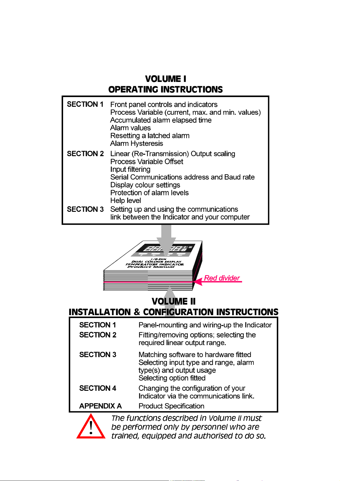
HOW TO USE THIS MANUAL
This manual comprises two volumes:
Page 3

59135
1
-DIN DUAL COLOUR DISPLAY
8
TEMPERATURE INDICATOR
Product Manual
Contents - Volume I
1 OPERATION MODE 1-1
1.1 FRONT PANEL 1-1
1.2 PARAMETER SEQUENCE 1-2
1.3 INPUT OVER-RANGE OR UNDER-RANGE 1-3
1.4 SENSOR BREAK 1-3
1.5 CHANGING AN ALARM VALUE 1-3
1.6 RESETTING A LATCHED ALARM 1-4
1.7 ALARM HYSTERESIS 1-4
1.8 SUMMARY OF PARAMETER IDENTIFIERS (SECONDARY DISPLAY) 1-4
2 PROGRAM MODE 2-1
2.1 ENTRY/EXIT 2-1
2.2 PARAMETER SELECTION 2-1
2.3 EDITING THE DISPLAYED PARAMETER (EDIT MODE) 2-2
2.4 PARAMETER SEQUENCE 2-3
3 SERIAL COMMUNICATIONS 3-1
3.1 DATA FORMAT/BAUD RATE 3-1
3.2 PROTOCOL 3-1
3.3 MESSAGE FORMAT 3-1
3.4 ERROR CONDITIONS 3-4
OM090-FM Volume I (iii)
Page 4
1 OPERATION MODE
This mode covers day-to-day operation of the Indicator.
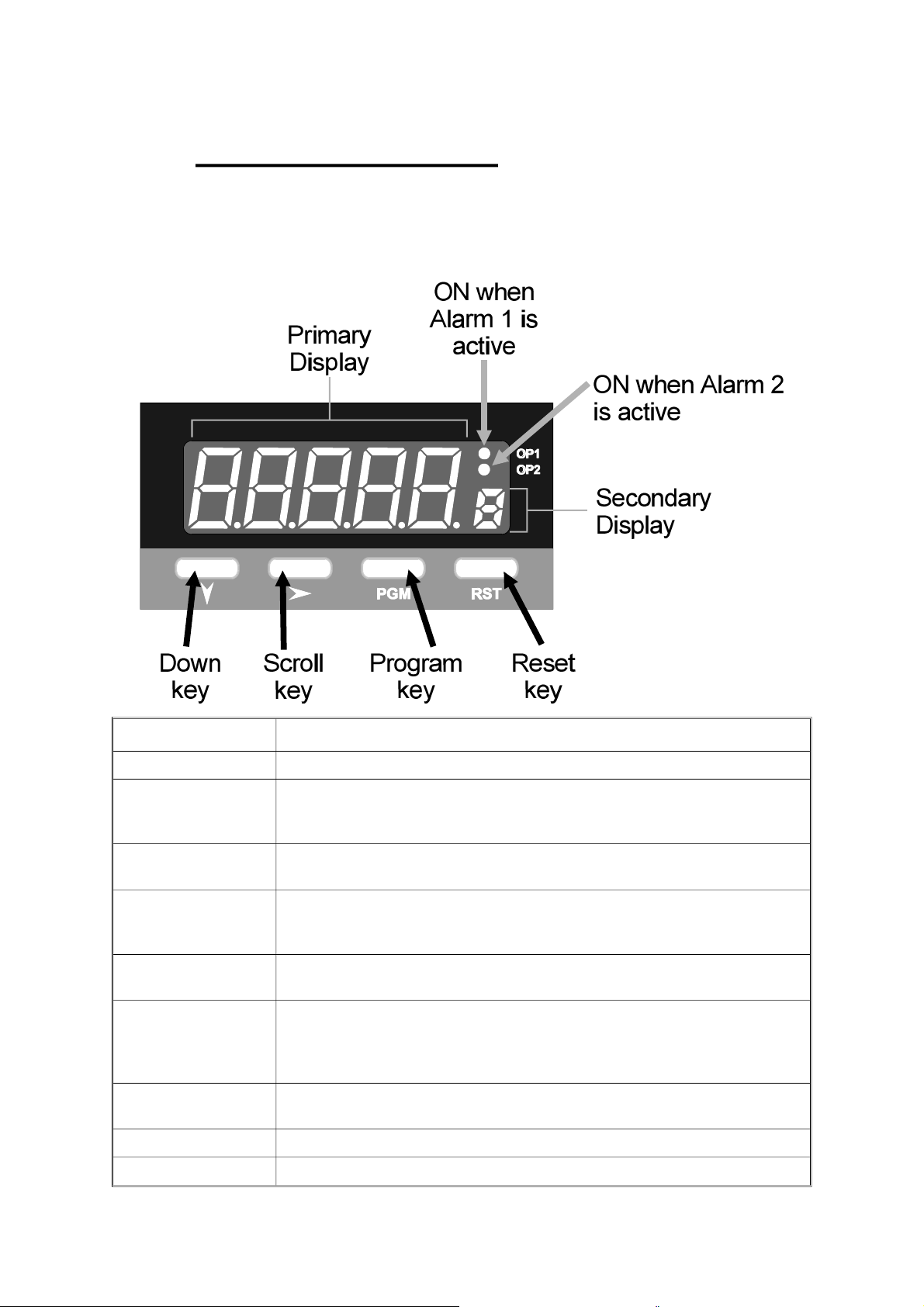
1.1 FRONT PANEL
59135
Key/Display/Indicator Function
Down key (Ú ) In Edit Mode, decrements the flashing digit in the Primary Display.
Scroll key (Ø ) Puts Indicator into Edit Mode; in Edit Mode, selects digit to be altered
(selected digit is flashing) in Primary Display. Wrap-around occurs from
right-most digit to left-most digit.
Program Key (PGM ) Selects parameter to be viewed/edited. In Edit Mode, confirms changed
parameter value.
Reset key (RST ) If the process variable is displayed, resets the latched Alarm 1. If the
Maximum (High) Value, Minimum (Low) Value or Alarm 1 Elapsed Time is
displayed, resets the displayed parameter.
Down (Ú ) and Scroll
(Ø ) keys
Primary Display Normally displays the process variable value. Displays other Operation
Secondary Display Shows a single-character identifier for the parameter value being
OP1 indicator ON when Alarm 1 is active.
OP2 indicator ON when Alarm 2 is active.
If pressed simultaneously in Edit Mode, will abort the Edit operation and
will restore the parameter to its initial value.
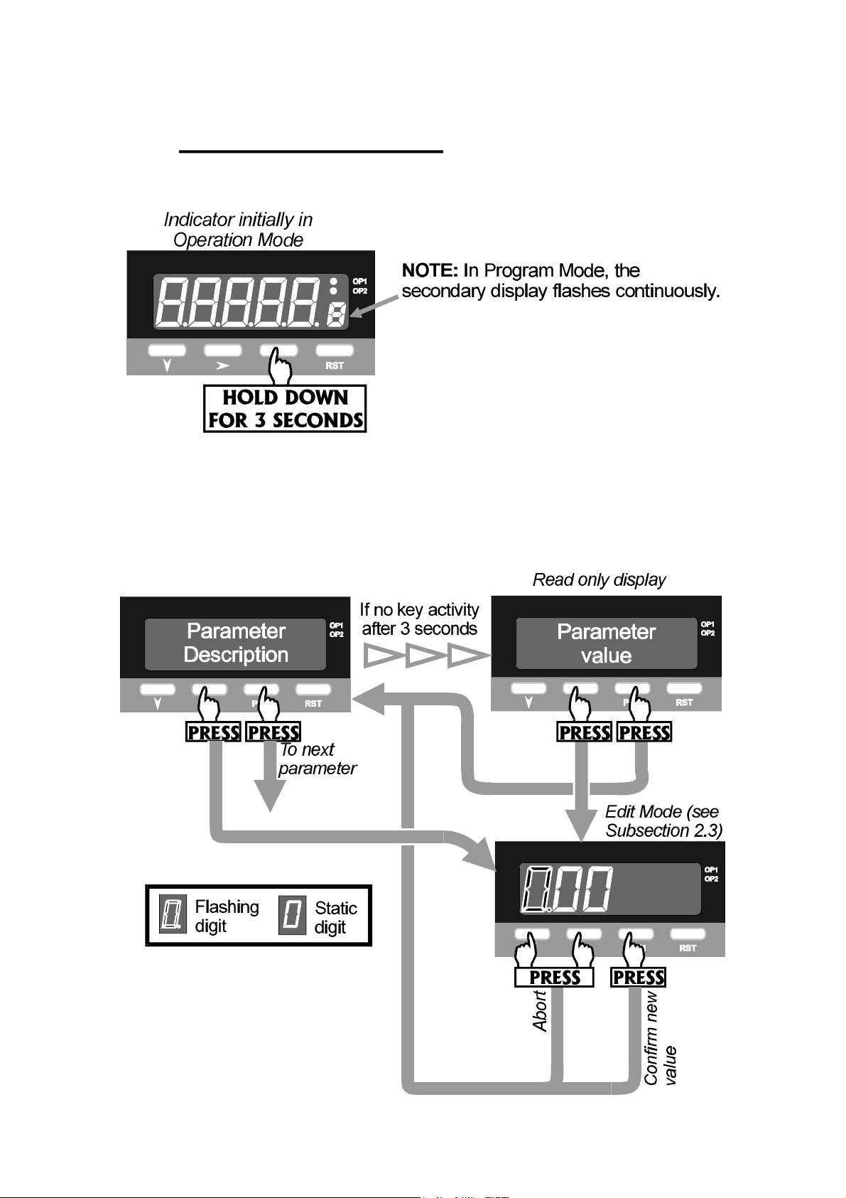
Mode parameters when the Program (PGM) key is used. If the Help
Facility is enabled (see Subsection 2.4), this display shows the parameter
description for three seconds before displaying the parameter value.
displayed (blank for process variable).
1-1 Volume I OM090-1
Page 5
59135
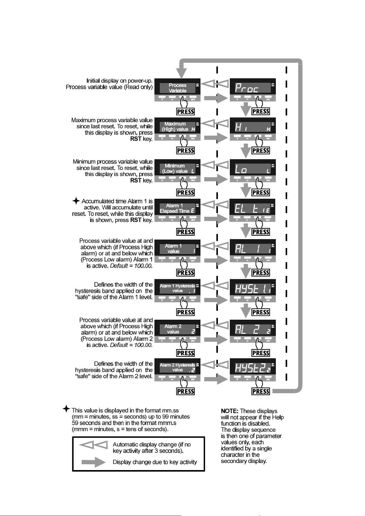
1.2 PARAMETER SEQUENCE
OM090-1 Volume I 1-2
Page 6
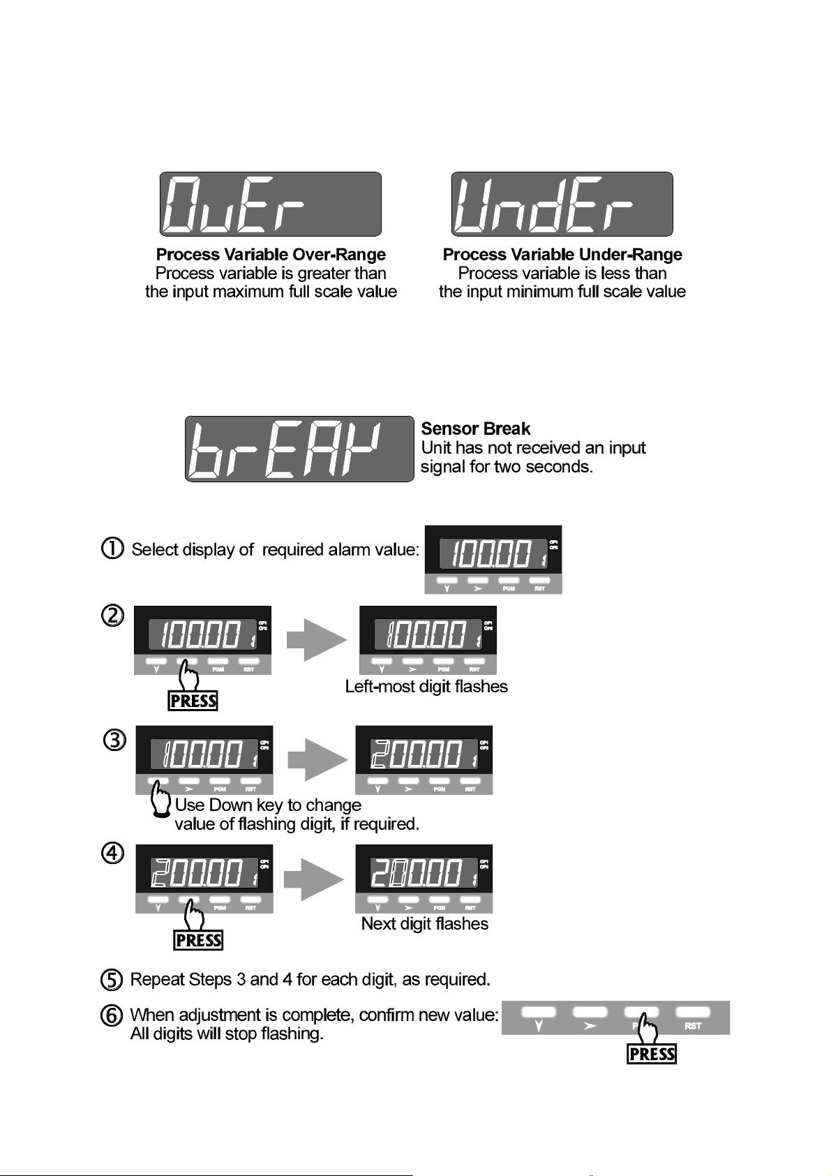
1.3 INPUT OVER-RANGE OR UNDER-RANGE
If the input becomes over-range or under-range, the primary display will show:
The display will disappear when the input returns within the input scale range.
1.4 SENSOR BREAK
This indicates that there is a break in the input sensor circuit.
59135
1.5 CHANGING AN ALARM VALUE
1-3 Volume I OM090-1
Page 7
59135
1.6 RESETTING A LATCHED ALARM
If Relay 1 is configured to act as a latched Alarm 1 relay, when this alarm is
active, it can be reset by selecting the process variable display and then pressing
the Reset (RST) key. The alarm will not be reset if the alarm condition exists at the
time reset is attempted.
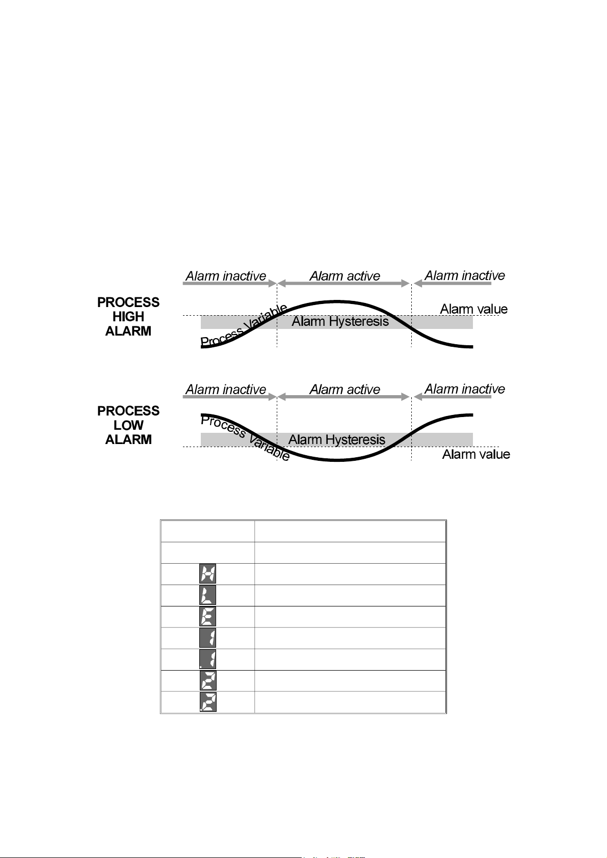
1.7 ALARM HYSTERESIS
The Alarm Hysteresis parameter applies a hysteresis band on the “safe” side of the
Alarm value. The effect of the hysteresis value (a percentage of input span) on the
operation of the different types of alarm is illustrated below:
1.8 SUMMARY OF PARAMETER IDENTIFIERS (SECONDARY DISPLAY)
Secondary Display Displayed Parameter
Blank Process variable
Maximum (High) value
Minimum (Low) value
Alarm 1 Elapsed Time
Alarm 1 value
Alarm 1 Hysteresis value
Alarm 2 value
Alarm 2 Hysteresis value
OM090-1 Volume I 1-4
Page 8
59135
2 PROGRAM MODE
2.1 ENTRY/EXIT
Use the Program (PGM) key in the same way to exit Program Mode (i.e. return to
Operation Mode).
2.2 PARAMETER SELECTION
2.2.1 With Help Facility Enabled
2-1 Volume I OM090-2
Page 9
59135
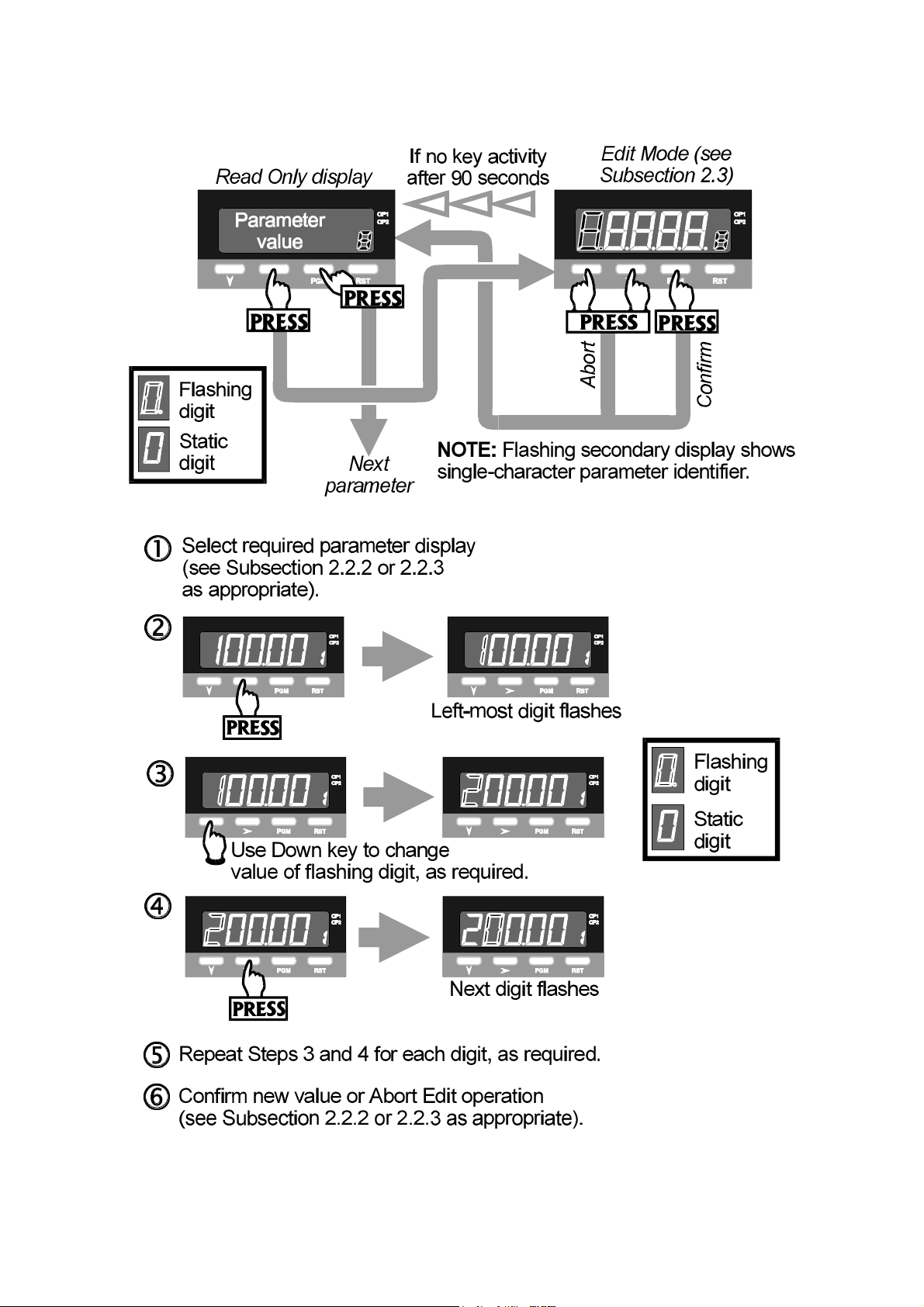
2.2.2 With Help Facility Disabled
2.3 EDITING THE DISPLAYED PARAMETER (EDIT MODE)
OM090-2 Volume I 2-2
Page 10
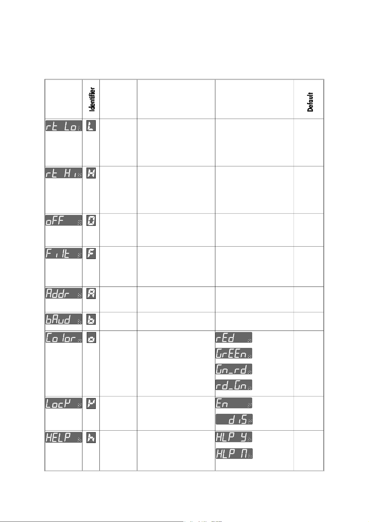
2.4 PARAMETER SEQUENCE
The Program Mode parameter sequence is as follows:
Parameter
Description
(Primary
Display)
Parameter Description Adjustment Range
59135
Retransmission
Scale
Minimum
Retransmission
Scale
Maximum
Process
Variable
Offset
Input Filter
Time
Constant
Communications
Address
The lower end of the linear
scale for the
re-transmission output,
expressed as the value
corresponding to the
minimum output signal.
The upper end of the
linear scale for the
re-transmission output,
expressed as the value
corresponding to the
maximum output signal.
Corrects a known offset of
the input in order to
display more accurately
the process value.
Filters the input over a
user-definable time period
to minimise the effect on
the process variable of
any extraneous impulses
The unique serial
communications address
of the instrument.
−19999 to 99999 −19999
−19999 to 99999
− 19999 to 99999
0.0 (OFF) to 100.0 2.0
1 to 99 1
99999
0.00
Baud Rate Serial communications
speed
Display
Colour
Change
Alarm Lock Enables/disables the
Help Prompt Determines whether the
Defines the colour of the
primary and secondary
displays prior to/after the
preset value (e.g. Alarm
level) is reached.
changing of alarm values
via the front panel.
Primary Display shows the
parameter description for
3 seconds before a
parameter value is shown.
1200, 2400, 4800 or 9600 4800
Red
Green
Green
to Red
Red to
Green
Enabled
Disabled
Yes
No
Green to
Red
Enabled
Yes
2 -3 Volume I OM090-2
Page 11

59135
3 SERIAL COMMUNICATIONS
The Serial Communications option is a standard RS485 communications link. Up to
32 standard RS485 loads may be presented to a single loop on this link. Each
Indicator presents ¼ standard, therefore up to 128 may be connected to a single
loop (ignoring the load presented by the master device). However, addresses are
restricted to the range 1 to 99.
3.1 DATA FORMAT/BAUD RATE
Data format is fixed at one start bit, seven data bits, 1 parity bit (even parity) and
1 stop bit i.e. a 10-bit data word. Baud rates supported are 1200, 2400, 4800 and
9600. The half-duplez line turn-round time is fixed at 6ms regardless of Baud rate.
The maximum inter-character delay is 120ms. The No Reply timeout is 2 seconds.
Data is expressed as a five-digit signed hexadecimal number in which the
following characters are permitted:
0 1 2 3 4 5 6 7 8 9 A B C D E F
Note that all the non-numeric characters are upper case. The detection of any
characters other than these will be regarded as a syntax error. Where a value
carries a decimal point, the point position is implicit and the responsibility for
interpreting it lies with the user.
3.2 PROTOCOL
The protocol operates on a single master basis only. All communication is initiated
by the master device.
The communications addresses available are in the range 1 - 99. Address 0 is
used for broadcast Parameter Write operation messages. When a message is
broadcast, the receiving instruments will attempt to implement the instruction but
will not reply.
3.3 MESSAGE FORMAT
Each message starts with a Start of Message character (L) and finishes with an End
of Message character (*). A reply from the addressed instrument will contain either
a positive acknowledgement or a negative acknowledgement. A positive
acknowledgement has the character A immediately preceding the End of
Message character; a negative acknowledgement has the character N
immediately preceding the End of Message character.
There are three message formats; they permit instrument identification, Parameter
Read operations and Parameter Write operations.
OM090-3 Volume I 3-1
Page 12

59135
3.3.1 Form 1 Message
The master device sends a Form 1 message to ascertain whether a specific
communications address is occupied by an instrument. If there is an instrument at
that address, a reply (with a positive acknowledgement) is received. If there is no
instrument at that address or if there is a communications link failure, no reply is
received. The message from the master device is of the form:
Laa??*
where aa is the address (a two-digit hexadecimal number). The reply from the
addressed instrument is of the form:
Laa?A*
where aa is the same address as in the received message.
3.3.2 Form 2 Message
This message implements a Parameter Read operation. The message from the
master device is of the form:
Laap?*
where aa is the address (a two-digit hexadecimal number)
p is a single-character parameter identifier (see Table 3-1)
The reply, if the Parameter Read operation is successful, is of the form:
LaapnnnnnA*
where aa is the same address as in the received message
p is a single-character parameter identifier (see Table 3-1)
nnnnn is the data (a five-digit hexadecimal number)
If the specified parameter is invalid (e.g. not applicable to the addressed
instrument), the reply is of the form:
Laap00000A*
where aa is the same address as in the received message
p is a single-character parameter identifier (see Table 3-1)
3-2 Volume I OM090-3
Page 13

59135
3.3.3 Form 3 Message
This message implements the Parameter Write operation either on a single
addressed instrument (address in the range 1 - 99) or broadcast to all instruments
connected to the master device (i.e. using address 00). Note that, with the
broadcast message, each slave instrument does not generate a reply. The
message from the master device is of the form:
Laapnnnnn*
where aa is the address (a two-digit hexadecimal number)
p is a single-character parameter identifier (see Table 3-1)
nnnnn is the value to be written (a five-digit hexadecimal
number)
The reply for a successful Parameter Write operation is of the form:
LaapnnnnnA*
where aa is the same address as in the received message
p is a single-character parameter identifier (see Table 3-1)
nnnnn is the value written (a five-digit hexadecimal number). In
cases in which this parameter does not exist or is not
applicable for the slave instrument, this value is 00000.
Iif a valid parameter is specified with an invalid value or an error condition is
encountered, the reply is of the form:
LaapnnnnnN*
where aa is the same address as in the received message
p is a single-character parameter identifier (see Table 3-1)
nnnnn indicates the error condition:
Value Error Condition
FFFFF Value under-range
7FFFF Value over-range
7FFFE Sensor Break detected
00001 Read Only parameter
00000 Illegal value
OM090-3 Volume I 3-3
Page 14

Table 3 -1 Parameter Identifiers and Adjustment Ranges
Identifier Hex. Parameter Adjustment Range
59135
: 3A Process Variable
< 3C Maximum Process Variable
= 3D Minimum Process Variable
Read Only (−19999 to 9999)
Read Only (−19999 to 9999)
Read Only (−19999 to 9999)
> 3E Elapsed Alarm 1 Time Read Only (0 to 60000)
@ 40 Reset Max. PV Write resets; Read always 0
A 41 Reset Min. PV Write resets; Read always 0
B 42 Reset Elapsed Alarm 1 Time Write resets; Read always 0
D 44 Reset Latched Alarm 1 Write resets; Read always 0
E 45 Alarm 1 value Range Max. To Range Min.
F 46 Alarm 2 value Range Max. To Range Min.
] 5D Re-transmitted Scale Min.
−19999 to Re-trans. Scale Max.
^ 5E Re-transmitted Scale Max. Re-trans. Scale Min. To 99999
_ 5F Process Variable Offset 0 to Range Span
‘ 60 Input Filter 0 to 1000 (0.0 to 100.0s)
a 61 Colour 0 to 3 (0 = Red, 1 = Green,
2 = Green/Red, 3 = Red/Green)
b 62 Alarm Lock 0 (lock enabled), 1 (lock disabled)
c 63 Help level 0 (Help enabled), 1 (Help disabled)
3.4 ERROR CONDITIONS
If a slave device detects a syntax error or parity error, it will not reply to the
message; the master device should make up to two retries, applying the
two-second No Reply timeout in each case.
Parameter Read operations with parameter identifiers which are in the legal
range but which are not applicable to the addressed instrument will have no
effect on any parameter values and a positive acknowledgement will be
returned.
Parameter Write operations with parameter identifiers which are outside the legal
range will be considered to be syntax errors; no reply will be generated.
Parameter Write operations in which the specified parameter is valid but the
specified value is invalid will generated a negative acknowledgement.
3 -4 Volume I OM090-3
Page 15

59135
1
-DIN DUAL COLOUR DISPLAY
8
TEMPERATURE INDICATOR
Product Manual
Contents - Volume II
The procedures described in this Volume must be undertaken only by
technically-competent servicing personnel.
1 INSTALLATION 1-1
1.1 UNPACKING 1-1
1.2 PANEL-MOUNTING 1-1
1.3 CONNECTIONS AND WIRING 1-3
2 INTERNAL LINKS AND SWITCHES 2-1
2.1 REMOVING THE INDICATOR FROM ITS HOUSING 2-1
2.2 REMOVING/REPLACING THE RELAY 2/LINEAR OUTPUT OPTION PCBs 2-3
2.3 REMOVING/REPLACING THE RS485 SERIAL COMMUNICATIONS
OPTION PCB/DIGITAL INPUT OPTION PCB 2-3
2.4 REPLACING THE INSTRUMENT IN ITS HOUSING 2-4
2.5 SELECTION OF LINEAR (RE-TRANSMISSION) OUTPUT RANGE 2-4
3 CONFIGURATION MODE 3-1
3.1 ENTRY/EXIT 3-1
3.2 PARAMETER SELECTION 3-1
3.3 EDITING THE DISPLAYED PARAMETER 3-2
3.4 PARAMETER SEQUENCE 3-3
4 SERIAL COMMUNICATIONS - CONFIGURATION MODE 4-1
PM090-FM Volume II (i)
Page 16

59135
Appendices
A PRODUCT SPECIFICATION A-1
A.1 DISPLAY A-1
A.2 SENSOR INPUT A-1
A.3 DIGITAL INPUT (OPTION) A-3
A.4 TRANSISTOR OUTPUTS A-3
A.5 RELAY 1 OUTPUT A-3
A.6 RELAY 2 OUTPUT (OPTION) A-4
A.7 LINEAR (RE-TRANSMITTED PV) OUTPUT (OPTION) A-4
A.8 SERIAL COMMUNICATIONS (OPTION) A-4
A.9 PERFORMANCE A-5
A.10 ENVIRONMENTAL A-7
A.11 PHYSICAL A-7
(ii) Volume II PM090-FM
Page 17

59135
1 INSTALLATION
1.1 UNPACKING
1. Remove the Indicator from its packing. The indicator is supplied with a
panel gasket and push-fit fixing strap. Retain the packing for future use.
2. Examine the delivered items for damage or deficiencies. If any is found,
notify the carrier immediately.
1.2 PANEL-MOUNTING
The panel on which the Indicator is to be
mounted must be rigid and may be up to
6mm (0.25 inches) thick. The cut-out
required for a single Indicator is shown in
Figure 1-1. Several indicators may be
mounted side-by-side in a single cut-out.
For n Indicators mounted side-by-side,
the cut-out dimensions would be (48n - 4)
millimetres or (1.89n - 0.16) inches. The
main dimensions of the Indicator are
shown in Figure 1 -2 .
Figure 1-1 Panel Cut-out
Figure 1-2 Main Dimensions
The panel-mounting procedure is shown in Figure 1 -3 .
CAUTION: Do not remove the panel gasket, as this may result in
inadequate clamping of the instrument in the panel.
PM090-1 Volume II 1-1
Page 18

59135
Figure 1-3 Panel-mounting
1.3 CONNECTIONS AND WIRING
The rear terminal connections are shown in Figure 1 -4 .
1 -2 Volume II PM090-1
Page 19

59135
Figure 1-4 Rear Terminal Connections
PM090-1 Volume II 1-3
Page 20

59135
1.3.1 Mains (Line) Supply
The Indicator will operate on 90 - 264V AC 50/60Hz mains (line) supply. The power
consumption is approximately 4 watts.
CAUTION: This equipment is designed for installation in an enclosure
which provides adequate protection against electric shock. Local
regulations regarding electrical installation should be rigidly
observed. Consideration should be given to prevention of access to
the power terminations by unauthorised personnel. Power should be
connected via a two-pole isolating switch (preferably situated near
to the equipment) and a 1A fuse, as shown in Figure 1 -4 .
If the Indicator has relay outputs in which the contacts are to carry mains (line)
voltage, it is recommended that the relay contact mains (line) supply should be
switched and fused in a similar manner but should be separate from the Indicator
mains (line) supply.
1.3.2 20 - 50V AC/DC Supply
Power should be connected via a two-pole isolating switch and a315mA
slow-blow (anti-surge Type T) fuse. With this option fitted, the Indicator will accept
20 - 50V AC @ 50/60Hz or 20 -50V DC in the polarity shown in Figure 1-4.
1.3.3 Thermocouple Input
The correct type of thermocouple extension leadwire or compensating cable
should be used for the entire distance between the Indicator and the
thermocouple, ensuring that the correct polarity is observed throughout. The
positive leg should be connected to Terminal 3 and the negative leg to Terminal
4. Joints in the cable should be avoided, if possible.
NOTE: Do not run thermocouple cables adjacent to power-carrying
conductors. If the wiring is run in a conduit, use a separate conduit
for the thermocouple wiring. If the thermocouple is grounded, this
must be done at one point only. If the thermocouple extension lead
is shielded, the shield must be grounded at one point only.
1.3.4 RTD Inputs
Three-wire or four-wire RTDs may be used. For three-wire RTDs, connect the resistive
leg of the RTD to Terminal 2, the common legs to Terminals 3 and 4 and a link
between Terminals 1 and 2. For four-wire RTDs, connect the resistive legs to
Terminals 1 and 2 and the common legs to terminals 3 and 4.
1 -4 Volume II PM090-1
Page 21

59135
1.3.5 Digital Input Option
Terminals 16 and 17, when this option is fitted, may be used for external selection
of the Security facility) which allows/prevents entry into Program Mode from the
front panel. These terminals may be connected to (a) the voltage-free contacts of
a switch or relay, or (b) a TTL-compatible voltage. With the Security option
configured (see Subsection 3.4), security selection is as follows:
Voltage-free Operation: Contacts open - Entry into Program Mode
prohibited
Contacts closed - Entry into Program Mode
permitted
TTL-compatible Operation: >2.0V - Entry into Program Mode
prohibited
<0.8V - Entry into Program Mode
permitted.
NOTE: This option and the Serial Communications option are
mutually exclusive.
1.3.6 Relay Outputs
Relay 1 is a standard feature; it is tied to Alarm 1. Relay 2 is an option; when fitted,
it is tied to Alarm 2. The contacts are rated at 2A resistive @ 120/240V AC.
1.3.7 Linear Output
This option provides a 10-bit linear output signal representing the process
variable. The range of this output is selectable in Configuration Mode (see
Subsection 3.4).
1.3.8 Serial Communications Option
The cable used should be suitable for data transfer at the selected rate (1200,
2400, 4800 or 9600 Baud) over the required distance. Transmitters/receivers
conform to the recommendations in the EIA Standard RS485.
The “A” terminal on the Indicator (Terminal 17) should be connected to the “A”
terminal on the master device; the “B” terminal on the Indicator (Terminal 16)
should be connected to the “B” terminal on the master device; the “Common”
terminal on the Indicator (Terminal 18) should be connected to the “Common”
terminal on the master device.
PM090-1 Volume II 1-5
Page 22

59135
Where several Indicators are connected to one master port, the master port
transceiver in the active state should be capable of driving a load of 120k Ω per
Indicator; the master port transceiver in the passive state must have
pull-up/pull-down resistors of sufficiently low impedance to ensure that it remains in
the quiescent state whilst supplying up to ± 100µA each to the Indicator
transceivers in the high impedance state.
NOTE This option and the Digital Input option are mutually exclusive.
1-6 Volume II PM090-1
Page 23

59135
2 INTERNAL LINKS AND SWITCHES
2.1 REMOVING THE INDICATOR FROM ITS HOUSING
CAUTION: Before removing the Indicator from its housing, ensure that
all power has been removed from the rear terminals.
To remove the Indicator from its housing, simply grip the side edges of the front
panel (there is a finger grip on each edge) and pull the instrument forward. This
will release the rear terminals from their connectors in the housing and will give
access to the PCBs. Take note of the orientation of the instrument for subsequent
replacement in the housing. The positions of the PCBs in the Indicator are shown in
Figure 2-1.
Figure 2-1 PCB Positions
PM090-2 Volume II 2-1
Page 24

59135
Figure 2-2 Removing the Relay 2/Linear Output Options PCBs
2-2 Volume II PM090-2
Page 25

59135
2.2 REMOVING/REPLACING THE RELAY 2/LINEAR OUTPUT
OPTION PCBs
With the Indicator removed from its housing:
1. Gently push the rear ends of the CPU PCB and Power Supply PCB apart
slightly, until the to tongues on each of the Relay 2 Option PCB and the
Linear Output Option PCB become disengaged - see Figure 2 -2 B; the Relay
2 Option PCB tongues engage in holes in the Power Supply PCB and the
Linear Output Option PCB tongues engage in holes in the CPU PCB.
2. Carefully pull the required Option PCB (Relay 2 or Linear Output) from its
connector (the Relay 2 Option PCB is connected to the CPU PCB and the
Linear Output PCB is connected to the Power Supply PCB) - see Figure 2 -2 C.
Note the orientation of the PCB in preparation for its replacement.
Adjustments may now be made to the link jumpers on the Linear Output Option
PCB (to select the output range - see Subsection 2.5).
2.3 REMOVING/REPLACING THE RS485 SERIAL
COMMUNICATIONS OPTION PCB/DIGITAL INPUT
OPTION PCB
The Serial Communications Option PCB or the DC Input Option PCB (the two are
mutually exclusive) is mounted on the inner surface of the Power Supply PCB and
can be removed from the unhoused Instrument by pulling the Option PCB towards
the rear of the Power Supply PCB. Figure 2 -3 illustrates the removal/replacement
procedure. It is not necessary to remove the Relay 2/Linear Output Option PCBs to
perform this procedure.
Figure 2-3 Removing/Replacing the Serial Communications/Digital
Input Option PCB
PM090-2 Volume II 2-3
Page 26

59135
2.4 REPLACING THE INSTRUMENT IN ITS HOUSING
To replace the instrument in its housing, simply align the CPU PCB and Power
Supply PCB with their guides and connectors in the housing and slowly but firmly
push the instrument into position.
CAUTION: Ensure that the instrument is correctly orientated. A stop will
operate if an attempt is made to insert the instrument in the wrong
orientation i.e. upside-down. This stop must not be over-ridden.
2.5 SELECTION OF LINEAR (RE-TRANSMISSION) OUTPUT
RANGE
If the Linear Output Option PCB is fitted, link jumpers on that PCB are used to select
the output range (see Figure 2 -4 and Table 2 -1 ).
Table 2 -1 Linear Output Range
Selection
Figure 2-4 Linear Output Option PCB
Output Range Link Jumper Fitted
0 - 10V DC LJ8
0 - 20mA DC LJ9
0 - 5V DC LJ8
4 - 20mA DC LJ9
2 -4 Volume II PM090-2
Page 27

59135
3 CONFIGURATION MODE
3.1 ENTRY/EXIT
Use these keys in the same way to exit from Configuration Mode.
3.2 PARAMETER SELECTION
3.2.1 With Help Facility Enabled
PM090-3 Volume II 3-1
Page 28

3.2.2 With Help Facility Disabled
59135
3.3 EDITING THE DISPLAYED PARAMETER
3-2 Volume II PM090-3
Page 29

59135
3.4 PARAMETER SEQUENCE
Parameter
Description
(Primary
Display)
Parameter Description Adjustment Range
Input
Range
Range
Trim High
Range
Trim Low
Power
Supply
Frequency
Alarm 1
Type
Selects the input sensor
type, resolution and
display scale (°C or °F)
by means of a code
number.
Adjusts the maximum
range value of the input
type selected.
Adjusts the minimum
range value of the input
type selected.
Applicable to
DC-powered units only,
this must be set to the
mains (line) frequency
for the site in order to
ensure proper filtering of
the input signal.
Defines the action of
Alarm 1
See Table 3 -1 .
Range Trim Low (see below) to
Range Max. (see Table 3-1).
Range Min. (See Table 3-1) to
Range Trim High (see above)
50Hz
60Hz
Process High
Process Low
No alarm
Range
Max.
Range
Min.
60Hz
Process
High
Alarm 2
Type
Output 1
Usage
Defines the action of
Alarm 2
Determines how NPN
Output 1 and Relay 1
operate.
Process High
Process Low
No alarm
Alarm 1, nonlatching, direct
action
Alarm 1, nonlatching, reverse
action
Alarm 1, latching,
direct action
Alarm 1, latching,
reverse action
Logical OR Alarm
1 & 2, direct
action
Logical OR Alarm
1 & 2, reverse
action
No
alarm
Alarm 1
nonlatching
direct
action
PM090-3 Volume II 3-3
Page 30

Parameter
Description
(Primary
Display)
59135
Parameter Description Adjustment Range
Output 2
Usage
Re-transmission
(Linear)
Output
Determines how NPN
Output 2 and Relay 2
operate.
Selects the scale for the
Re-transmission (Linear)
Output
Alarm 2, direct
action
Alarm 2,
reverse action
Logical OR
Alarm 1 & 2,
direct action
Logical OR
Alarm 1 & 2,
reverse action
None
0 - 5V
1 - 5V
0 - 10V
2 - 10V
0 - 20mA
4 - 20mA
Alarm 2,
direct
action
None
Option
Selection
Determines whether the
Serial Communications
Option or Digital Input
Option is fitted
None
Serial Comms.
Digital Input
None
3-4 Volume II PM090-3
Page 31

59135
Table 3 -1 Input Range Codes
Input Type Range Code Range Minimum Range Maximum
Thermocouple Inputs
J
100 (°C)
101 (°F)
110 (°C)
111 (°F)
T
200 (°C)
201 (°F)
210 (°C)
211 (°F)
K
300 (°C)
301 (°F)
310 (°C)
311 (°F)
N
400 (°C)
401 (°F)
B
500 (°C)
501 (°F)
R
600 (°C)
601 (°F)
–200
–328
–128.0
–198.4
–240
–400
–128.0
–198.4
–240
–400
–128.0
–198.4
0
32
100
212
0
32
1200
2192
537.0
998.6
400
752
400.0
752.0
1372
2502
537.0
998.6
1399
2550
1824
3315
1760
3200
S
3-wire
4-wire
700 (°C)
701 (°F)
800 (°C)
801 (°F)
810 (°C)
811 (°F)
900 (°C)
901 (°F)
910 (°C)
911 (°F)
RTD Inputs
0
32
–200
–328
–128.0
–198.4
–200
–328
–128.0
–198.4
1760
3200
800
1472
537.0
998.6
800
1472
537.0
998.6
PM090-3 Volume II 3-5
Page 32

59135
4 SERIAL COMMUNICATIONS -
CONFIGURATION MODE
This section is a supplement to the information provided in Volume I, Section 3 and
describes the Read/Write communications operations which can be performed in
Configuration Mode.
Table 4 -1 Parameter Identifiers and Adjustment Ranges - Configuration Mode
Identifier Hex. Parameter Adjustment Range
d 64 Enter Configuration Mode Read:0 - Not in Configuration Mode
1 - In Configuration Mode
Write:1 - Enter Configuration Mode
e 65 Exit Configuration Mode Read:0 - In Configuration Mode
1 - Not in Configuration Mode
Write:1 - Exit Configuration Mode
f 66 Input Type For range of values, see Table 4-2.
g 67 Range Trim Maximum Range Trim Minimum to Range
Maximum (see Table 4-2)
h 68 Range Trim Minimum Range Minimum (see Table 4-2) to
Range Trim Maximum
i 69 Mains (Line) Frequency.
(Applicable to
DC-powered units only)
j 6A Alarm 1 Type 0 No alarm
k 6B Alarm 2 Type 0 No alarm
NOTE: All Configuration Mode parameters are Read Only when
the instrument is not in Configuration Mode, Read/Write
when the instrument is in Configuration Mode.
0 (50Hz) or 1 (60Hz)
1 Process High
2 Process Low
1 Process High
2 Process Low
Continued on next page ⇒⇒⇒⇒⇒
4-1 Volume II PM090-4
Page 33

59135
Table 4 -1 Parameter Identifiers and Adjustment Ranges - Configuration Mode
Identifier Hex. Parameter Adjustment Range
l 6C Output 1 Use 0 Alarm 1 non-latching,
direct action
1 Alarm 1 non-latching,
reverse action
2 Alarm 1 latching, direct action
3 Alarm 1 latching, reverse
action
4 Logical OR Alarm 1 & 2,
direct action
5 Logical OR Alarm 1 & 2,
reverse action
m 6D Output 2 Use 0 Alarm 2, direct action
1 Alarm 2, reverse action
2 Logical OR Alarm 1 & 2,
direct action
3 Logical OR Alarm 1 & 2,
reverse action
n 6E Select Re-transmission
(Linear) Output Range
0 None
1 0 - 5V
2 1 - 5V
3 0 - 10V
4 2 - 10V
5 0 - 20mA
6 4 - 20mA
NOTE: All Configuration Mode parameters are Read Only when
the instrument is not in Configuration Mode, Read/Write
when the instrument is in Configuration Mode.
PM090-4 Volume II 4-2
Page 34

Table 4 -2 Input Type Selection - Available Values
Input Type Range Code Range Minimum Range Maximum Hex. Value
Thermocouple Inputs
59135
J
100 (°C)
101 (°F)
110 (°C)
111 (°F)
T
200 (°C)
201 (°F)
210 (°C)
211 (°F)
K
300 (°C)
301 (°F)
310 (°C)
311 (°F)
N
400 (°C)
401 (°F)
B
500 (°C)
501 (°F)
R
600 (°C)
601 (°F)
–200
–328
–128.0
–198.4
–240
–400
–128.0
–198.4
–240
–400
–128.0
–198.4
0
32
100
212
0
32
1200
2192
537.0
998.6
400
752
400.0
752.0
1372
2502
537.0
998.6
1399
2550
1824
3315
1760
3200
0
1
2
3
4
5
6
7
8
9
0A
0B
0C
0D
0E
0F
10
11
S
3-wire
4-wire
700 (°C)
701 (°F)
800 (°C)
801 (°F)
810 (°C)
811 (°F)
900 (°C)
901 (°F)
910 (°C)
911 (°F)
0
32
RTD Inputs
–200
–328
–128.0
–198.4
–200
–328
–128.0
–198.4
1760
3200
800
1472
537.0
998.6
800
1472
537.0
998.6
12
13
14
15
16
17
18
19
1A
1B
4-3 Volume II PM090-4
Page 35

59135
APPENDIX A PRODUCT SPECIFICATION
A.1 DISPLAY
Type: Red/green, seven-segment LED, five-digit
primary display, one-digit secondary
display.
Height: 0.71 inches (18mm) primary display
0.3 inches (7mm) secondary display
Annunciators: Alarm 1 and Alarm 2 status.
A.2 SENSOR INPUT
Types: Type B, J, K, N, S and T thermocouples
Three-wire and four-wire RTD
Accuracy: 0.1% of span
Sample Rate: Every 250mS.
Resolution: 14 bits.
Sensor Break Detection: Detected within two seconds.
Input Ranges Available: See Table A -1.
PM090-A Volume II A-1
Page 36

Table A -1 Input Type Selection - Available Values
Input Type Range Code Range Minimum Range Maximum
Thermocouple Inputs
59135
J
100 (°C)
101 (°F)
110 (°C)
111 (°F)
T
200 (°C)
201 (°F)
210 (°C)
211 (°F)
K
300 (°C)
301 (°F)
310 (°C)
311 (°F)
N
400 (°C)
401 (°F)
B
500 (°C)
501 (°F)
R
600 (°C)
601 (°F)
–200
–328
–128.0
–198.4
–240
–400
–128.0
–198.4
–240
–400
–128.0
–198.4
0
32
100
212
0
32
1200
2192
537.0
998.6
400
752
400.0
752.0
1372
2502
537.0
998.6
1399
2550
1824
3315
1760
3200
S
3-wire
4-wire
700 (°C)
701 (°F)
800 (°C)
801 (°F)
810 (°C)
811 (°F)
900 (°C)
901 (°F)
910 (°C)
911 (°F)
RTD Inputs
0
32
–200
–328
–128.0
–198.4
–200
–328
–128.0
–198.4
1760
3200
800
1472
537.0
998.6
800
1472
537.0
998.6
A-2 Volume II PM090-A
Page 37

59135
A.3 DIGITAL INPUT (OPTION)
Type: Voltage-free or TTL-compatible operation.
May be connected to: External switch/relay contacts or
TTL-compatible logic signal.
Maximum Input delay
(open - closed or “1" - “0"
transition):
Minimum Input delay
(closed - open or “0" - “1"
transition):
External Switch/Relay Contacts
Maximum Contact
Resistance (Closure):
Minimum Contact
Resistance (Open):
External TTL-Compatible Logic Signal
Maximum Voltage (TTL) for
“0”:
1 second
1 second
50
5000
0.8V
Minimum Voltage (TTL) for
“0":
Minimum Voltage (TTL) for
“1":
Maximum Voltage (TTL) for
“1":
-0.6V
2.0V
24.0V
A.4 TRANSISTOR OUTPUTS
Type: NPN open collector. Output tied to Alarm 1,
Output 2 tied to Alarm 2.
A.5 RELAY 1 OUTPUT
Contact Type: Single pole double throw.
Rating: 5A resistive @ 120/240V AC
PM090-A Volume II A-3
Page 38

Lifetime: >500,000 operations at rated
voltage/current.
Isolation: Inherent
A.6 RELAY 2 OUTPUT (OPTION)
Contact Type: Single pole double throw.
Rating: 5A resistive @ 120/240V AC
Lifetime: >500,000 operations at rated
voltage/current.
Isolation: Inherent
A.7 LINEAR (RE-TRANSMITTED PV) OUTPUT (OPTION)
59135
Ranges available: 0 - 5V, 1 - 5V, 0 - 10V, 2 - 10V, 0 - 20mA
and 4 - 20mA.
Accuracy: 0.25% (mA @ 250W, V @ 2kW); degrades
linearly to 0.5%.
Resolution: 8 bits in 250mS (10 bits in 1 second
typically).
Update Rate: 4/second approximately.
Load Impedance: mA ranges - 500W max.
V ranges - 500W min.
A.8 SERIAL COMMUNICATIONS (OPTION)
Type: Serial asynchronous, UART to UART.
Data Format: Open ASCII; One start bit, even parity,
seven data bits, one stop bit.
Physical Layer: RS485.
Maximum Number of
Zones:
Baud Rate: Selectable from 1200, 2400, 4800 and
A-4 Volume II PM090-A
99.
9600 Baud.
Page 39

59135
A.9 PERFORMANCE
Reference Conditions
Ambient Temperature:
Relative Humidity: 60 - 70%
Supply Voltage: 90 - 264V AC 50Hz
Source Resistance: <10Ω for thermocouple input
Lead Resistance: <0.1Ω/lead balanced (Pt100)
20°C ±2°C
Performance Under Reference Conditions
Common Mode Rejection: >120dB at 50/60Hz giving negligible effect
at up to 264V 50/60Hz.
Series Mode Rejection: >500% of span (at 50/60Hz) causes
negligible effect.
Thermocouple Inputs
Measurement Accuracy:
±0.05% typical, ±0.1% maximum, of span
±1LSD. NOTE: Reduced performance with
Type “B” Thermocouple below 600°C
(1112 °F).
Linearisation Accuracy:
Cold Junction
Compensation:
RTD Inputs
Measurement Accuracy:
Linearisation Accuracy:
Operating Conditions
Ambient Temperature:
High resolution ranges - better than ±0.5°C
Low resolution ranges - better than ±0.05 °C
±0.3% typical, ±0.5% maximum.
±0.02% typical, ±0.06% maximum, of span
±1LSD
High resolution ranges - better than ±0.5°C.
Low resolution ranges - better than
±0.05 °C.
0°C to 55 °C
PM090-A Volume II A-5
Page 40

Relative Humidity: 20% - 95% non-condensing
Source Resistance: 1000 Ω maximum (thermocouple)
Lead Resistance: 50Ω per lead maximum balanced (Pt100)
Performance Under Operating Conditions
59135
Temperature Stability:
Cold Junction
Compensation
(thermocouple only):
0.005% of span/°C change in ambient
temperature.
Better than ±1°C.
A.10 ENVIRONMENTAL
EMI Susceptibility: Complies with EN50082-1:1992,
EN50082-1:1995. NOTE: For RF
electromagnetic fields (10V/m 80% AM
1kHz), the reading accuracy may be
impaired by up to 3oC in the frequency
band 273 to 470MHz and by up to 1.4oC
in the frequency band 785 to 1000MHz.
EMI Emmissions: Complies with EN50081-1:1992,
EN50081-2:1993.
Safety: Complies with EN61010-1.1993.
Supply Voltage: 90 - 264V, 50/60Hz (standard)
20 - 50V AC/DC (option)
Power Consumption: 4watts approximately
Front Panel Sealing: To IP66 (Nema 4)
A.11 PHYSICAL
Dimensions: Height - 48mm
Width - 96mm
Depth - 100mm
Mounting: Panel-mount; press-fit fixing strap supplied.
Panel cut-out - 45mm x 92mm
Terminals: Screw type; combination head.
Weight: 0.21kg maximum.
A-6 Volume II PM090-A
 Loading...