

Page 1
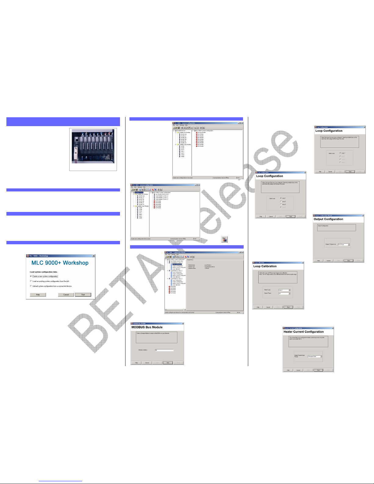
The MLC 9000+ is a DIN-rail-mounted multiloop PID control system that can be connected
to a variety of fieldbus systems. The MLC
9000+ system consists of a single Bus Module
and any combination of up to 8 Loop Modules.
The Bus Module is a supervisory module
connected directly to the DIN rail. It provides
power to the Loop Modules and contains a
back-up of the system configuration data. It
also manages the communications with
external devices.
The Loop Modules are independent control
modules managed by the Bus Module. They are connected to the DIN rail via an interconnect module that provides power and communications from the Bus Module. Any
combination of Loop Module types can be connected to the Bus Module, as long as the
maximum of eight modules is not exceeded.
Remove the Bus Module and Loop Modules from there packing and install them as
described in their installation manuals. Connect the configuration cable supplied with the
MLC 9000+ Workshop software to the RJ11 port of the Bus Module and to the RS 232 port
of the PC. The MLC 9000+ is now ready for configuration. (More information on the
hardware installation can be found in the MLC 9000+ User Guide)
1. Insert the installation disk into the CD drive on your PC. The Set-up program should
start automatically; If it does not, navigate to the appropriate drive using Windows
Explorer and double click the Set-up icon.
2. The Set-up Wizard will guide you through the installation procedure.
3. You will be prompted to define a folder into which you want the Configurator installed.
You may use the default folder or specify one of your own choice.
The first screen displayed on start-up is an options menu. This options menu gives you
three choices:
1. Create a new System Configuration: This option is for configuration of an MLC
9000+ system without the physical hardware being connected to the PC.
2. Load an existing System Configuration from the disk: This option loads a
configuration that has already been saved previously.
3. Upload System Configuration from a connected device: This option gathers
the system configuration information from an MLC 9000+ system that is
connected to the RS 232 port of the PC.
To create a new configuration select ‘Create a new System Configuration’ and press Start,
this will then take you to the system configuration screen. If the Bus Module is new and has
never been configured this option must be selected as the Bus module will have no
configuration.
To navigate through the different configuration screens of the MLC 9000+ Workshop
software select View in the menu bar or use the buttons in the task bar.
The system configuration
screen is used to define which
Bus Module and Loop Modules
are used in the MLC 9000+
system.
The Left hand column is a list
of all the Bus Module and Loop
Module drivers available. The
right hand column is a blank
system. To insert a module into
the system drag from the
available modules in the left
hand column and drop in an
available slot in the right hand
column. The first module to
add is the Bus Module. Select
a Bus Module type and drag
and drop it into the Bus Module
slot. The Loop Modules can
then be added in any order.
When adding modules ensure
that the physical hardware is
installed in the same
configuration. For example if the
physical MLC 9000+ system is a
BM230-DN Bus Module and
three Z3611 Loop Modules the
system configuration entered
must be the same.
Once System Configuration is
complete proceed to the
Configuration Wizard using the
View | Configuration wizards
menu option or by pressing the
wizard button.
The configuration wizard
screen is used to
configure the control
characteristics of the
LCMs and the standard
communication
parameters of the Bus
Module. In the left hand
column are all the
modules that were
added during System
Configuration.
Click on the + sign next
to the module. A list of
the available
configuration wizards is
then displayed. To
activate a wizard double
click on the wizard
name.
Each Bus Module type has a wizard that can
be used to configure the communication
parameters required for successful
communication.
All Loop Modules have three common wizards:
1. Loop Configuration: This wizard is for
configuration of the most common control
loop parameters in the module.
For single loop controller modules (Z1200,
Z1300, and Z1301) the loop configuration only
gives you the option to configure a single loop.
For multi-loop controller modules (Z3611,
Z3621, Z4610 and Z4620) the loop
configuration gives you the option to
configure multiple loops with the same
configuration at the same time. This then
reduces the time required to configure
multiple loops.
2. Output Configuration: This wizard is
used to allocate the outputs to specific
tasks and in the case of the multi-loop
Loop Modules which loop they will work
with.
Any of the outputs in a single loop module
can be assigned any task. For multiple loop
modules each control loop needs to be
assigned an output.
3. Loop Calibration: This wizard is for
calibration of the inputs. It should only be
used if you are sure that the input is out of
calibration.
WARNING: Incorrect calibration will cause the
MLC 9000+ to malfunction
For modules that have the Heater Current input (Z1301, Z3611 and Z3621) there is a
separate wizard
1. HARDWARE INSTALLATION
MLC 9000+ Quick Start Guide 59328-1
Figure 1 – A Typical MLC 9000+
System
2. INSTALLING MLC 9000+ WORKSHOP
3. RUNNING MLC 9000+ WORKSHOP
4. SYSTEM CONFIGURATION
5. CONFIGURATION WIZARDS
Page 2
Select the Data Assemblies screen using View | Data Assemblies or the Data Assemblies
button.
A Data Assembly is a user-defined collection of parameters that the Bus
Module collects from its Loop Modules so that the master device (PLC, SCADA or HMI)
can collect the required parameter data in one message transaction.
There are two user definable data assemblies. These are 1) Read - parameters that are to
be transferred from the MLC 9000+ to the supervisory system and 2) Write - parameters
that are to be transferred from the supervisory system to the MLC 9000+.
In the left hand column are all the parameters that can be mapped to the data assemblies
for transfer to or from the supervisory system and on the right are the two data assemblies.
To populate the data assemblies select a parameter from the list then drag and drop it into
the read or write tables. MLC 9000+ will not allow read only parameters to be placed into
the write data assembly.
Word parameters are shown with a W and bit parameters are shown with a B. If a bit
parameter is dragged onto a word register the register is converted into 16 bits. The full 16
bits can then be filled with any combination of bit parameters. If a word parameter is placed
into that bit register then it is then converted back to a word register and the bit
configuration is lost.
A summary of the data assembly
information can be created by
selecting the ‘summary’ icon
in
the tool bar
Once the system has been configured it can be saved by clicking on the save icon in
the tool bar or navigate to File | Save as.
Some Fieldbus protocols require a GSD/EDS file for configuration of the master device.
MLC 9000+ Workshop generates this file once the data assemblies have been populated.
Click on the create GSD/EDS icon
in the tool bar this will activate the create
GSD/EDS wizard that will guide you through the creation of the GSD/EDS file.
To download the configuration to the MLC 9000+ click on the icon in the tool bar, this
will activate the download wizard which will guide you through the download process.
The MLC 9000+ system can be adjusted using the expert view and monitored using the
Monitoring view.
Adjusting Parameters in Expert view
The expert view contains all the parameters that can be edited in a full system.
In the left hand column are the modules as configured in the system configuration, by
clicking on the + sign next to the module the tree view is expanded and all the parameter
classes are displayed.
When a class is selected all the parameters for that class are displayed on the right.
Clicking on the value of a parameter enables that parameter to be edited. When all
required parameter changes have been made the configuration can be download to the
MLC 9000+ by clicking on the Download configuration icon.
To work online select
Settings | Work Online.
This will then make the
expert view live so that
any changes made will be
downloaded to the MLC
9000+ immediately
.
WARNING: Care must be taken when working online as changing certain parameters may
cause others to change automatically (i.e. when the input range is changed the scaling is
defaulted)
CAUTION: When working online it is advised that steps are taken to ensure damaging
conditions can not be caused.
Monitoring View
In the left hand column are
all the parameters that can
be viewed, organised by
module and class. To
monitor a variable double
click the parameter name.
It will then appear in the
right hand column.
.
Your PC should meet the following minimum requirements for satisfactory operation of the
software:
Windows 2000
PC with 400 megahertz (MHz) or higher processor clock speed recommended; 133-MHz
minimum required;*
128 megabytes (MB) of RAM or higher recommended (64 MB minimum supported)
64 megabytes (MB) of available hard disk space.*
Super VGA (800 × 600) or higher resolution video adapter and monitor
CD-ROM or DVD drive
Keyboard and Mouse or compatible pointing device
Windows XP
PC with 800 megahertz (MHz) or higher processor clock speed recommended; 233-MHz
minimum required;*
256 megabytes (MB) of RAM or higher recommended (64 MB minimum supported)
64 megabytes (MB) of available hard disk space.*
Super VGA (800 × 600) or higher resolution video adapter and monitor
CD-ROM or DVD drive
Keyboard and Mouse or compatible pointing device
* Actual requirements will vary based on your system configuration and the applications
and features you choose to install. Additional available hard disk space may be required if
you are installing over a network.
6. CONFIGURING THE FIELDBUS COMMUNICATIONS (DATA ASSEMBLIES)
8. GENERATING THE GSD/EDS FILE
9. DOWNLOADING THE CONFIGURATION TO THE MLC 9000+
7. SAVING A SYSTEM CONFIGURATION
10. ADJUSTING AND MONITORING A LIVE SYSTEM
11. MLC 9000+ WORKSHOP SYSTEM REQUIREMENTS
 Loading...