

Page 1

Industrial controller KS 94
Operating Instruction
9499 040 44211
S94
Gültig ab: 8363
Page 2

Inhalt
1. Front view ..............5
2. Safety notes .............5
3. Electromagnetic compatibility . . . 5
4. Technical data r data sheet,
order no. 9498 737 28233 ......5
5. Maintenance / Behaviour in case
of trouble ...............6
6. Further information.........6
7. Mounting ...............6
8. Electrical connections ........7
8.1 Notes . . . . . . . . . . . . . . . . . 7
8.2 Connecting input INP1 . . . . . . . . 7
8.3 Connecting input INP6 . . . . . . . 8
8.4 Connecting input INP5 . . . . . . . 8
8.5 Connecting the power supply . . . . 8
8.6 Connecting the outputs OUT2/4/5 . . 8
8.7 Connecting output OUT1 . . . . . . 8
8.8 Digital inputs and outputs (di / do) . 8
8.9 Connecting the bus interface . . . . 9
8.10 Connecting the inputs INP3 / INP4 . 9
8.11 Connecting the output OUT3 . . . . 9
8.12 Versions with integr. supply voltage 10
9. Operation (survey) .........11
9.1 The menues 1...3 . . . . . . . . . . 11
9.2 The operating level . . . . . . . . . 11
9.3 Operating the programmer: . . . . . 12
9.4 Calibration: ............12
9.5 DAC – motor actuator monitoring . .
(Digital Actor Control DAC®) . . . . .13
9.6 Self-tuning (automatic optimization of
control parameters) . . . . . . . . .13
9.7 Parameter and configuration level . 14
10. Configuration............15
10.1 General . . . ............15
10.2 Basic structure. . . . . . . .....15
10.3 Main groups . . . . . . . . .....18
10.4 CONTR: Controller . . . . . . . . . 19
10.5 SOURCE: Input signal allocation . . 21
10.6 INPUT: inputs . . . . . . . .....23
10.7 OUTPT: outputs. . . . . . . . . . . 27
10.8 ALARM: alarms ..........31
10.9 TUNE:self-tuning ..........32
10.10 DISP: User interface for operation . 32
10.11 AUX: Additional functions . . . . . 33
10.12 Examples of configuration . . . . . 35
11. Parameters .............36
11.1 General . . . ............36
11.2 Set-point function ..........38
11.3 Time function . . . . . . . .....38
11.4 Programmer functions . . . . . . . 38
11.5 Alarm function . . . . . . . . . . . 39
11.6 Self-tuning. . . . . . . . . . . . . . 39
11.7 Control algorithm ..........40
11.8 Input processing . . . . . . . . . . . 41
11.9 Miscellaneous . . . . . . . .....42
11.10 Signals . . . . . . . . . . . . . . . . 42
12. Versions ...............43
13. ....................43
13.1 Input and output allocation with . . .
pre-configured units. . . . . . . . .....44
Symbol definition:
a
K
J
DAC
General warning (caution, following the warnings in the instruction)
Protective earth
Earth connection
®
is a patented method and a registered trademark of Regeltechnik Kornwestheim GmbH.
All rights reserved. No part of this documentation may be reproduced or published in any form
or by any means without prior written permission from the copyright owner
A publication of PMA Proze- und Maschinen-Automation. Subject to alterations without notice.
PMA Prozess- und Maschinen-Automation GmbH 2000, Printed in Germany (2003).
PMA Prozess- und Maschinen-Automation GmbH • P.O.Box 310 229 • D-34058 Kassel - Germany
Page 3

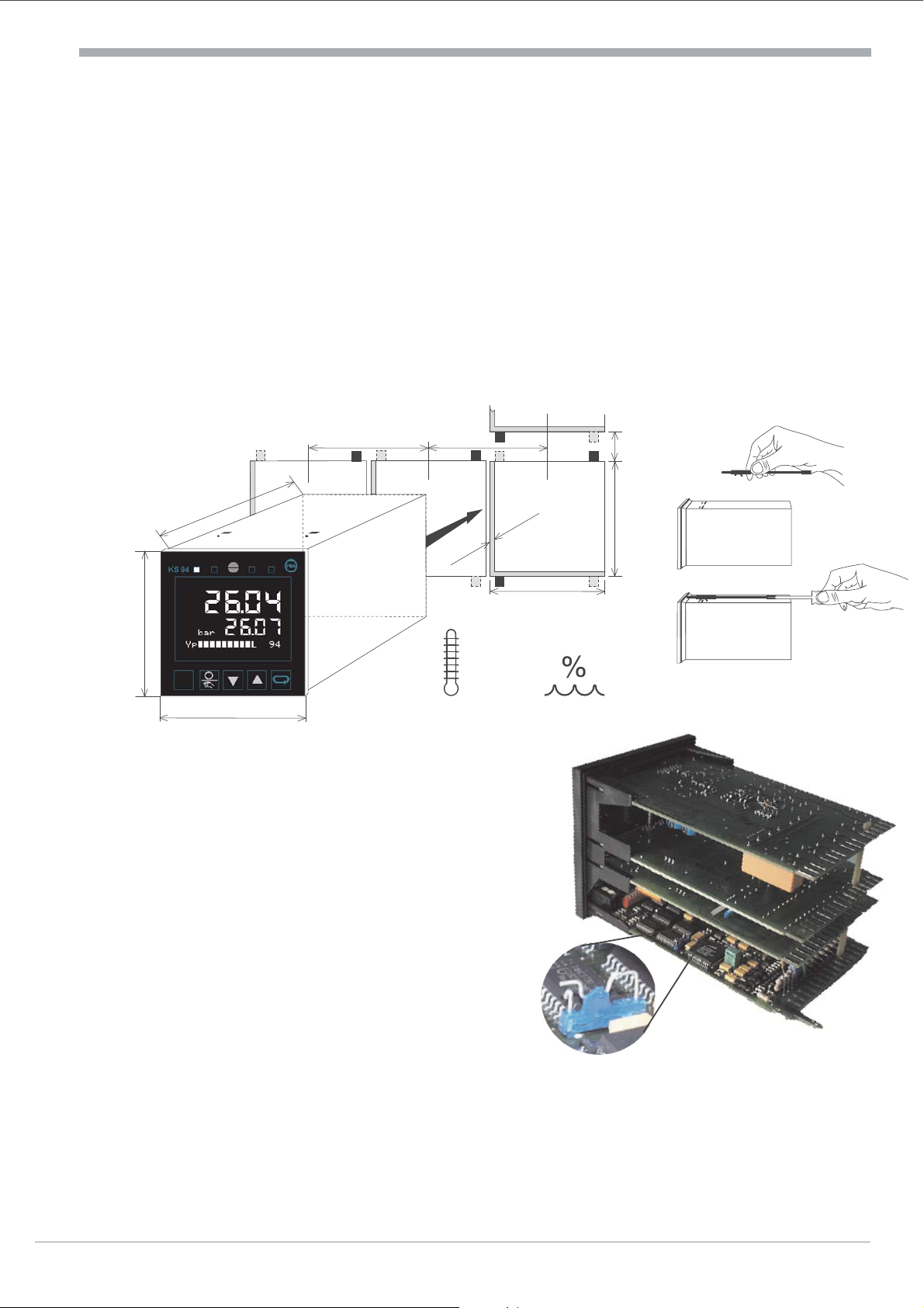
1. Front view
English
LED 2 e.g. Cooling LED 3 e.g. Alarm 1
LED 1 e.g. Heating LED 4 e.g. Alarm 2
Text 1 e.g. physical unit Display 2 e.g. Set-point
Text 2 e.g. Bargraph / Dialogue
Manual/Automatic key Decrement key (u)
Locking screw: Locks the controller module in the housing.
w
Front view
Locking screw
Display 1 e.g. Process value
Selection key
PC interface Increment key (z)
LEDs: indicates the statuses of controller outputs Y1, Y2 and alarms LIM1, LIM2 (other settings at
w
configuration level C.800 r page 30).
Display 1: indicatess process value at operating and parameter level, or the configuration code at
w
configuration level.
Display 2: indicates the set-point (automatic mode) or the correcting value (manual mode) in operating
w
level. The values are adjustable directly with ID. Further displays at operating level r page 9. In
parameter and configuration level, values and codes described with text1 are indicated (r page 12).
w
Text 1: indicates the short-form dialogue or the unit of display 2.
w
Text 2: indicates the output bargraph (other selections possible in configuration level C.800).
Keys HDIM: For the certain function r pages 9 and 12.
w
PC interface: PC connection for configuration/parameter setting/operation with an engineering tool.
2. Safety notes
Following the enclosed safety instructions 9499 047 07101 is indispensable!
The insulation of the instrument conforms to EN 61 010-1 with pollution degree 2, overvoltage
category III, operating voltage 300 V and protection class I. Additional with horizontal installation, a
protection to prevent live part, e.g. wire ends, from dropping into the open housing of a withdrawn
controller must be fitted.
3. Electromagnetic compatibility
The instrument conforms to European Directive 89/336/EEC and will be provideed with the
CE-marking. The following European Generic Standards are met: Emission: EN 50081-2 and
Immunity: EN 50082-2. The unit is suitable for use in industrial areas (in residential areas, RF
interference may occur). The electromagnetic radiation can be reduced decisively by installing the
unit in a grounded metal switch cabinet.
4. Technical data r data sheet, order no. 9498 737 28233
5 Operating instruction KS94
Page 4
Maintenance / Behaviour in case of trouble
96
96
96 96
92
+0,8
92 ?24
+0,8
1...16
160
2
1
8.8.8.8
8.8.8.8
min. 0°C
50°Cmax.
max.
95% rel.
W2:ÀC
Y:ыыыыыо 55%
5. Maintenance / Behaviour in case of trouble
The controller needs no maintenance. The rules to be followed in case of trouble are:
Check mains (voltage, frequency and correct connections),wcheck, if all connections are correct,
w
check the correct funktion of the sensors and final elements,wcheck the configuration words for
w
required functions andwcheck the adjusted parameters for required operation. If the controller still
does not work properly after these checks, shut down the controller and replace it.
Cleaning:Housing and Front can be cleaned by means of a dry, lint-free cloth. No use of solvents or
cleansing agents!
6. Further information
A manual with the order no. 9499 040 44811 gives further information to the chapters of this
operating notes.
7. Mounting
S.I.L. switch: with the switch closed, transition to
parameter and configuration level is disabled.
When making an attempt to change over to the
parameter level, ”ParaL” is displayed (text1).
Correcting variable, set-point and parameters at
the ”extended operating level” remain available
for selecting and changing. For access to the S.I.L.
switch, release the locking screw and withdraw the
instrument module from the housing. Subsequently,
re-insert the controller module into the housing and
mount it with screws.
Protection mode IP65: 4 fixing clamps must be
used. The instruments insert must be placed strongly
an locked strongly by means of the locking screw.
l
Operating instruction KS94 6
Caution! The instrument contains ESD-hazarded
components.
Page 5
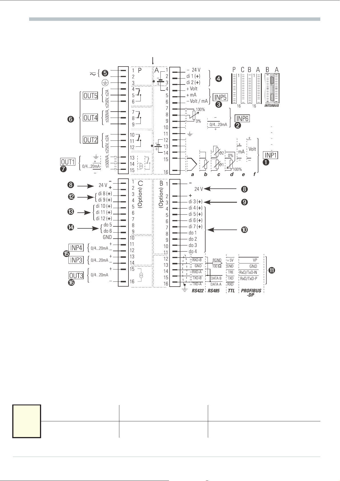
8. Electrical connections
Electrical connections
galvanic isolation
* Versions with integrated supply voltage (connection example look at page 10)
8.1 Notes
q
q
q
The ground connection of earth terminal A11 (terminal P13 with continuous controllers, too) should
be kept separate from the mains and as short as possible (15 cm during test). Keep mains cables
separate from signal and measurement input leads. We recommend twisted and screened
measurement input leads (screen contacted to measurement earth).
When connecting a contactor to a relay output, an RC protective circuit is necessary, to avoid voltage
peaks which can cause trouble to the controller.
Individual or common fuse protection must be fitted (1 A per instrument).
8.2 Connecting input INP1 1
Input for main process value x1 (actual value).
Thermocouple
x1
a
d
Potentiometric transducer
b
e
Resistance thermometer
(Pt 100)
Current (0/4...20mA)
7 Operating instruction KS94
Temperature difference (}1-}2)
c
(2x Pt 100)
f
Voltage (0/2...10V)
Page 6

Electrical connections
8.3 Connecting input INP6 2
For position feedback with 3-point stepping controller
(other selections possible in configuration level C.180).
8.4 Connecting input INP5 3
Input for process value x2 or external set-point or external
set-point offset (configuration level C.180). With voltage signals,
x2
8.5 Connecting the power supply 5
8.6 Connecting the outputs OUT2/4/5 6
8.7 Connecting output OUT1 7
A6 must be connected to the reference potential at A9.
Depending on the version, the instrument is supplied with: 90...250 V AC or 24 V UC. The
24 V UC version is for 19,2...30 V DC or 20,4...26,4 V AC. The indicated values are the limits. The
protective earth must be connected to terminal P3.
Relay outputs, corresponding to the controller output Y2 or the alarms LIM1 / LIM2 (other selections
possible in configuration level rfrom page 26).
Depending on the version, OUT1 is a relay, logic or continuous output corresponding to the
controller output Y1 (other selections in configuration level). With logic and continuous outputs, P13
must be connected to the earth terminal. The logic signal is 0 / >20 mA (load ß600 [)or0/>12V
(load ?600 [).
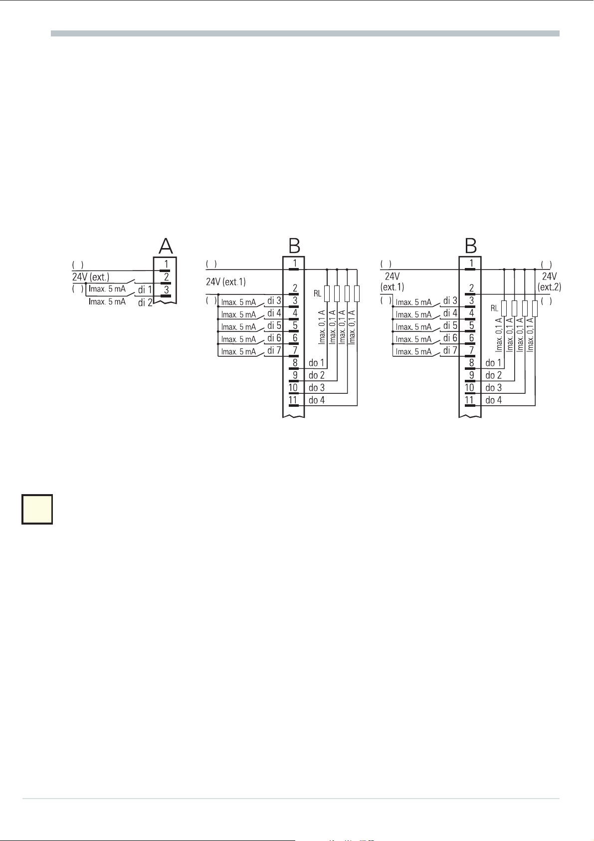
8.8 Digital inputs and outputs (di / do) 4890"§$
The inputs operate as current sink (IEC 1131 type1), logic „0" = -3...5 V, logic “1" = 15...30 V.
The outputs operate as „grounded load“. They are short circuit protected and contain recovery diodes.
The digital input and supply voltage (24V) must be connected on each circuit board.
4 di1 / di2 control various actions (set in configuration level C.190/ C.191 and
parameter Blck1 / Blck2)
9 di3 is used for changeover Local mode(0) i Remote mode(1).
0 di4...di7 and do1...do4 are correlated to the programmer as follows:
di4 Program STOP (0) i RUN (1) do1 Status fo control output 1
di5 Program normal (0) i RESET (1) do2 Status fo control output 2
di6 Program number (LSB) do3 Status fo control output 3
di7 Program number (MSB) do4 Status fo control output 4
di6 0 1 0/1 di8 0101
di7 0 0 1 di9 0011
program 1 2 3 parameterset 0123
" di8 / di9 is used for selecting the parameter set (bei C.700 = xx.x.3, di9 = MSB).
Operating instruction KS94 8
Page 7
Electrical connections
§ di10 is the input for override control OVC+ (three-point stepping).
di11 is the input for override control OVC- (three-point stepping) or the correction of the
effective set-point OFF (0) i ON (1) (configuration level C.190 / C.191).
di12 switches the bumpless transfer of the internal set-point (tracking) OFF (0) i ON (1) or
switches from set-point w (0) i w2 (1) (configuration level C.190 / C.191).
$ do5 or do6 indicates the status automatic i manual or internal i external set-point or the
status of the controller outputs Y1 / Y2 with switching controllers (configurations C.596 / C.597).
8 The digital inputs and outputs must be supplied from one or several external 24 V dc sources
(current consumption 5 mA/input, max. load = 0,1 A/output). Examples:
Digital inputs (connect. A) Digital inputs and outputs with
one dc source (e.g. connector B)
-
+
-
+
8.9 Connecting the bus interface !
TTL level or RS422, RS485, PROFIBUS or INTERBUS. With TTL level, an interface module for
conversion to RS422/RS485 is required. 4 units may be connected to an interface module.
8.10 Connecting the inputs INP3 / INP4 %
Digital inputs and outputs with
two dc sources (e.g. connector B)
-
+
-
+
Selectable in configuration level as e.g. process variable x2, process variable x3, auxiliary variable z,
x3
ext. set-point or over ride control (OVC). The reference potential of the inputs is at C10.
8.11 Connecting the output OUT3 &
Depending on the version, OUT3 is a logic or continuous output (C.560). The logis signal is
0 / >20 mA (load ß600 [) or 0 / >12 V (load ?600 [). The signals are available, see page 28.
The function can be selected with configuration code C.560. By means of code C.565, the output
can be connected to a post processing (e.g. linearisation).
9 Operating instruction KS94
Page 8
Electrical connections
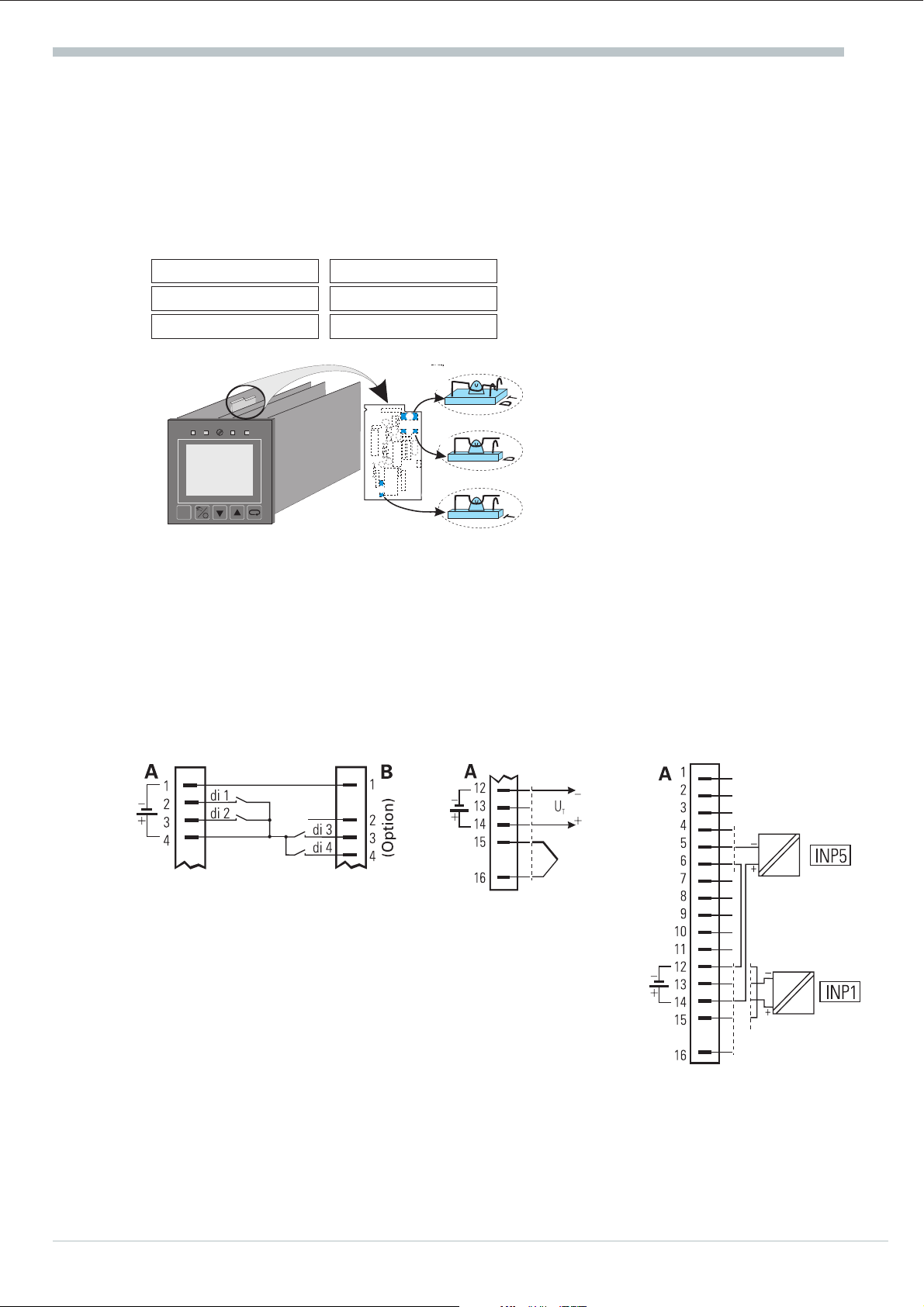
8.12 Versions with integrated supply voltage
The supply voltage can be used only for energization of a 2-wire transmitter or for energization of
max. 4 control inputs. The supply voltage is potential-free and can also be used for energizing inputs
INP3 ... INP6 or for other units. Selection of supply voltage or digital inputs is by S.I.L. switches (see
figure opposite).
Transmitter
supply voltage
Ü
Position T Position D
* open
Ö
closed (T)
8.8.8.8
W2:ÀC
8.8.8.8
Y:ыыыыыо 55%
a
The supply voltage is only applied to terminals A12 and A14 with INP1 configured for
current or thermocouple (C.200; type) and the S.I.L. switches set for transmitter supply
(factory setting)! With the S.I.L. switches set to digital input, the voltage is applied to
terminals A1 and A4 independent of the configuration of input INP1. In this case, the voltage
input of INP5 is not available.
Digital input
closed (D)
open
Ü
T
Ü
D
D
*
*
Ö
T
Ö
Supply voltage for energization of
digital input (e.g. di1...di4)
External use of the supply
voltage
Connection of a 2-wire
transmitter on example of
INP1 or INP5
Operating instruction KS94 10
Page 9
9. Operation (survey)
Operation (survey)
+
The user manual (order no. 9499 040 44811) is required for the complete operation.
9.1 The menues 1...3
Apart from the parameter and configuration words, the following dialogue words are used (Text1):
Text1 Signification
CBus CFrnt
Clear
Clock
Conf
End
Exit
Hold
Mark
More
OStar OStop
Para
PRun PStop
PSet PRes
Quit
PC communication via interface at terminals B12...B16 or connection on the unit front
The additional display selected at operating level is deleted (r Mark)
Adjust the clock
Transition to configuration level
Return to the previous selection menu
Return to operating level (main display)
The displayed parameter is determined as standard indication.
The displayed parameter is stored as additional display at operating level (r Clear)
The configuration level area described with MORE is accesible
Self-tuning will be started or stopped
Transition to parameter level
Programmer will be started or stopped
Programmer will be set to a specified program point or reset to the reset point
Return to operating level (main display) without storage of the values changed last
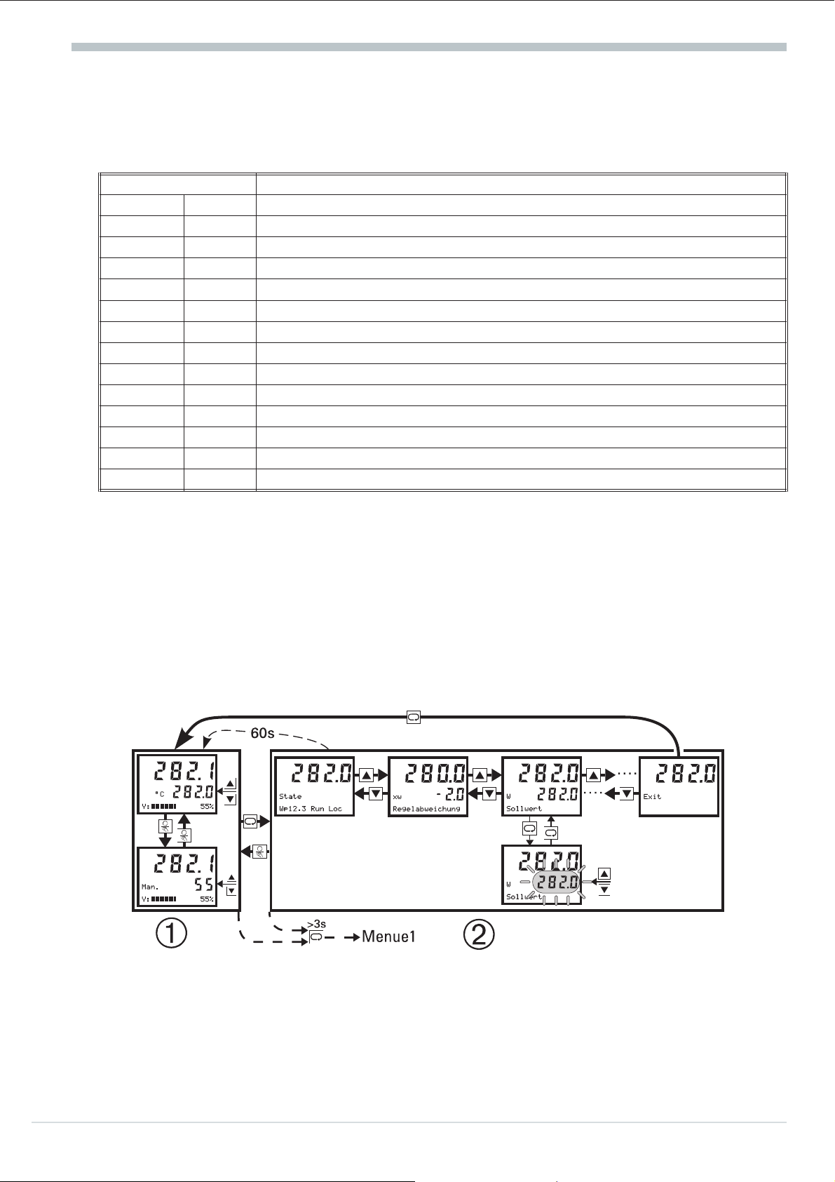
9.2 The operating level
The operating level comprises main display Ü and extension *. During the main display, automatic
or manual operation can be selected (H). With automatic, the set-point, and with manual, the
correcting value can be adjusted directly (ID). In the extension, the number and sequence of
displays is dependent of selected functions. Max. 12 parameters from the parameter level can be
displayed (Mark i Clear). Some of these parameters are directly adjustable (ID). A parameter
can be displayed continuously with the Hold function. (PressM <3sÄ Select parameter (press
ID) ÄM>3sÄ Select Hold (Press ID) ÄM). The extension can be left with Exit and M
or after a timeout of 60 s or with H. With H, the other operating mode is also selected.
+
If the set-point is set to ‘——‘ by means of D, the controller is switched off!!
Menu 1 is always selectable at operating level: deletion of additional display (Clear),
communication interface switch-over (CBus i CFrnt) and starting (OStar) or stopping
(OStop) the self-tuning, setting the clock (Clock), operate the programmer (PRun i PStop;
PRes; PSet) and transition to parameter level (Para).
11 Operating instruction KS94
Page 10

Operation (survey)
+
c
0
Status display: In the extended operation of KS94, ‘Text2’ indicates the
controller status. The following table shows the possible
displays:
Set-point
Meaning Status Meaning Status Meaning
Symbol)
.....
We
Wp
xx.
y
W2
Internal set-point
External set-point
Program set-point
Segment number
Program number
2nd set-point
....
Band
End
Grw
Rset
Run
Stop
9.3 Operating the programmer:
The programmer can be operated (run, stop, reset, preset) with menu 1, via digital inputs or via the
interface (process management system).
Operating Level
No bandalarm and no
programmer active
Band width control has stopped
programmer or set-point ramp.
End of program is reached
Set-point gradient is limiting the
speed of change
Programmer in reset mode
Programmer is running
Programmer has been stopped
Menu 1
(flashes)
...
Rem
KS94 in local mode
(Front operation
possible)
KS94 in remote mode
(Front operation
blocked)
When entering the preset time (parameter setting: Pmode = 1) the time can be entered up to 99.59 in
hours . minutes, or only in hours with longer times.
9.4 Calibration:
+
a
Calibation is only possible with the controller set to manual mode. Calibration from INP1/6 (Typ=
40; Potentiometric transducer) is in two steps.
w
Select x0c Ä Press M (c blinking) Ä set transducer to 0%, wait 6s and confirm with M.
w
Select x100c Ä Press M (c blinking) Ä set transducer to 100%, wait 6s and confirm with M.
Manual calibration of INP6 is only possible with the DAC function switched off. With the DAC
function switched on, automatic calibration is possible (r DAC page 11 ).
w
For selecting YpCal , press ÄM(0 blinks) change to 1 with I and acknowledge with M
r automatic calibration is started.
Operating level
270
Man.
xw____áûô___ 12%
The parameter X0c and X100c can be allocated to the extended operating level.
10.5
+
>3s
M
I
D
End
Hold
OStar
Para
M
End
I
Signl
D
Aux
Input
Contr
Tune
Limit
Setp
M
+
I
D
I
D
End
Cal
End
INP6
INP1
+
M
M
+
I
D
I
D
End
X100c
X0c
YpCal
End
X100c
X0c
+
M
M
+
0
X0c
Operating instruction KS94 12
Page 11
Operation (survey)
9.59.5 DAC – motor actuator monitoring (Digital Actor Control DAC®)
With all controllers with position feedback Yp, the motor actuator can be monitored for functional
troubles.
CFunc = 08 = 3-point stepping controller with position feedback as a potentiometer
CFunc = 09 = continuous with position feedback as a potentiometer
CFunc = 12 = continuous with current feedback via Yp (INP6)
The system detects the following stepping controller errors:
defective motor
w
defective capacitor (wrong rotating direction),
w
wrong phase followers
w
defective force transmission at spindle or drive,
w
excessive backlash due to wear
w
jamming of the control valve e.g. due to foreign body
w
With the continuous controllers, monitoring if output signal and position feedback exceed a
difference of 10 % after elapse of a 20 s filter time is provided. The DAC® function can be switched
on or off at parameter setting level (DAC = 0/1). A detected trouble is indicated, the controller
switches to manual mode and no pulses are output any more.
a
During Yp calibration, the DAC® function is activated! Otherwise, disabling would be
detected when reaching the limits and the controller would be switched to “off” (r
calibration).
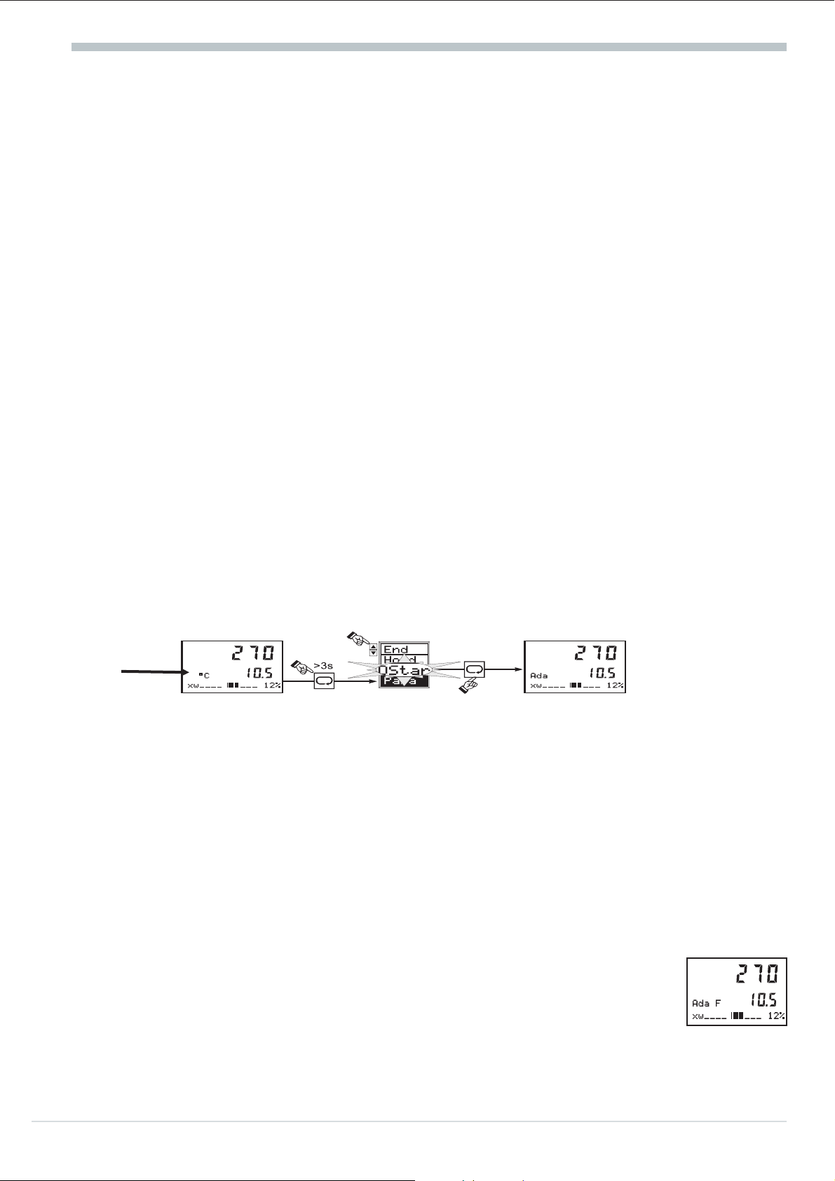
9.6 Self-tuning (automatic optimization of control parameters)
After starting by the operator, the controller makes an attempt for optimization by determining the
parameters for fast line-out at the set-point without overshoot from the process characteristics.
Optimization start:the operator can start the optimization attempt at any time (see opposite drawing).
Preparation for self-tuning:
•
PID, PI, PD or P control behaviour can
be selected by the user by switching off
Tn=0 or Tv=0 before self-tuning start.
•
Determine which parameter set shall be
optimized (POpt).
Self-tuning cancelation:
The operator can cancel the optimization attempt at any time. This is possible by pressing key H
(Äcontroller switches to ‘manual’) or via OStop in menu1 (Ä controller switches to `automatic’).
The controller continues operating with the old parameter values.
•
Determine the output step change (dYopt).
•
Determine the stable correcting variable (YOptm).
•
Determine the `process-at-rest’ mode ( C.700 ; OCond)
•
Is the set-point reserve (x-w) > 10% of W100-W0?
Optimization problems:
With process conditions which prevent successful optimization, the controller cancels
the attempt for optimization (Ada F is displayed). The controller outputs are
switched off to prevent the set-point from being exceeded. Afer self-tuning
cancelation, controlling is continued with the old parameter values.
13 Operating instruction KS94
Page 12
Operation (survey)
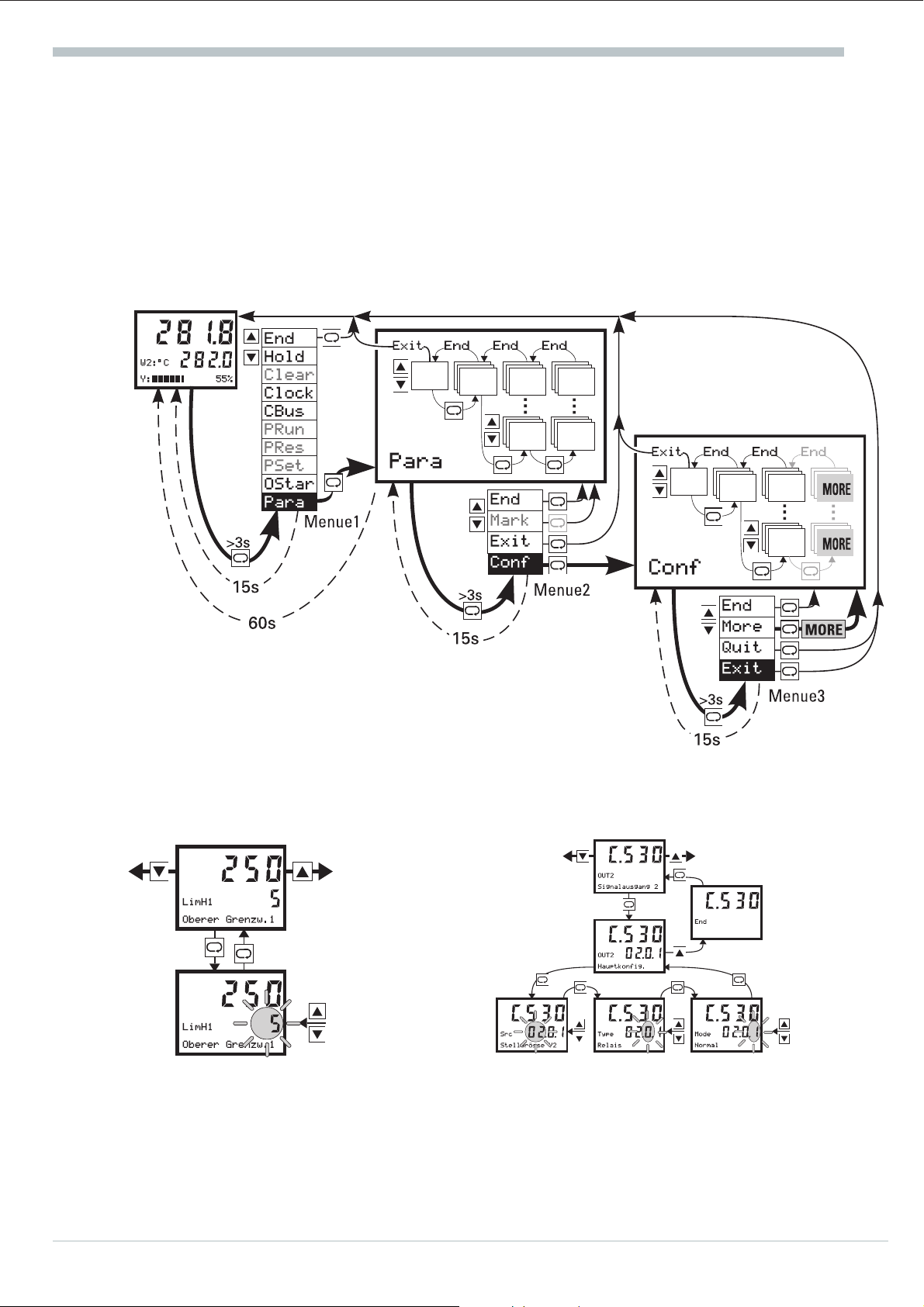
9.7 Parameter and configuration level
Menu 1 is always selectable at operating level: several operations (r 7.2) and transition to parameter
level (Para).
Menu 2 is always selectable at parameter level: selection of additional displays (Mark), return to
parameter level (End), return to operating level (Exit), transition to configuration level (Conf).
Menu 3 is always selectable at configuration level: permitting the MORE area (More), return to
configuration level (End), return to operating level without storage of the last changes (Quit)or
with storage of the changes (Exit).
Value adjustment is as follows (parameter values / configuration codes):
Example for a single value Example for combined data (e.g. C-codes)
Operating instruction KS94 14
Page 13
10. Configuration
10.1 General
The KS94 controller configuration for quick and easy function selection during subsequent operation
is described in this section. During configuration, the required functions are selected from a large
variety of available functions. The configuration determines the basic structure for solution of an
application.
The configuration structure is designed so that determination of the required functions for a large
number of applications is possible by adjustment of as few configuration words as possible.
Moreover, the structure was designed flexible enough to permit additional configurations also for
realization of special applications.
10.2 Basic structure
The first menu level permits selection of the main configuration group.
The user can be guided through all function configurations, or he can configure the specific functions
required for his application directly.
Configuration
For all ‘complex’ main groups, a two-level configuration concept which enables the user to select the
‘correct’ setting for his application by defining only one configuration word was determined. If
necessary, special functions can be determined separately. For the ‘normal user’, however, the
configuration words are preset to purposeful default values! For simplification, the hierarchic
configuration dialogue is structured so that the user can and must adjust only the ‘required’
configuration words.
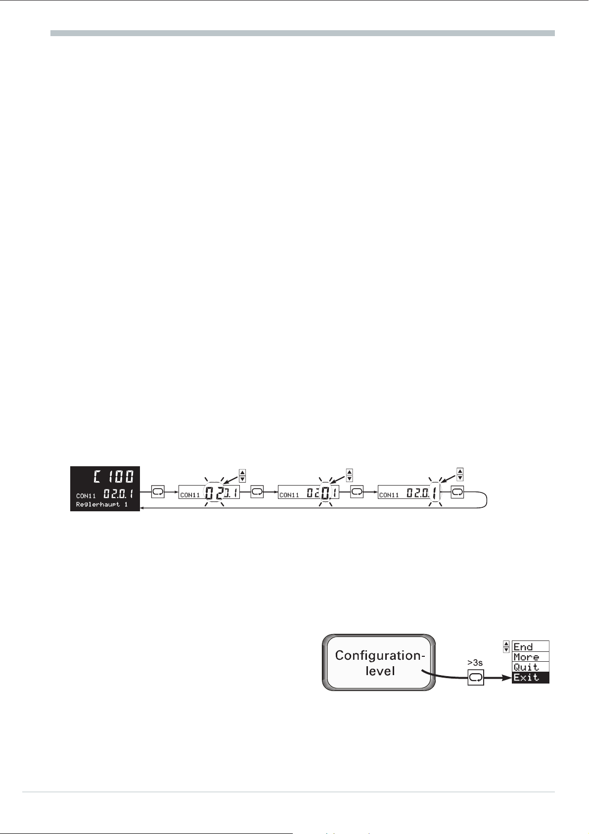
The user configuration dialogue is started via selector key M and ‘increment’ / ‘decrement’ keys
ID, like with the other KS92/94 operating levels:
w
Press the selector key to select menu items / input values / input positions within a ‘level’ and to
change over to the next higher level at the end of a ‘level’.
w
Press the ‘increment’ / ‘decrement’ keys for returning to a lower level and for modification of input
values.
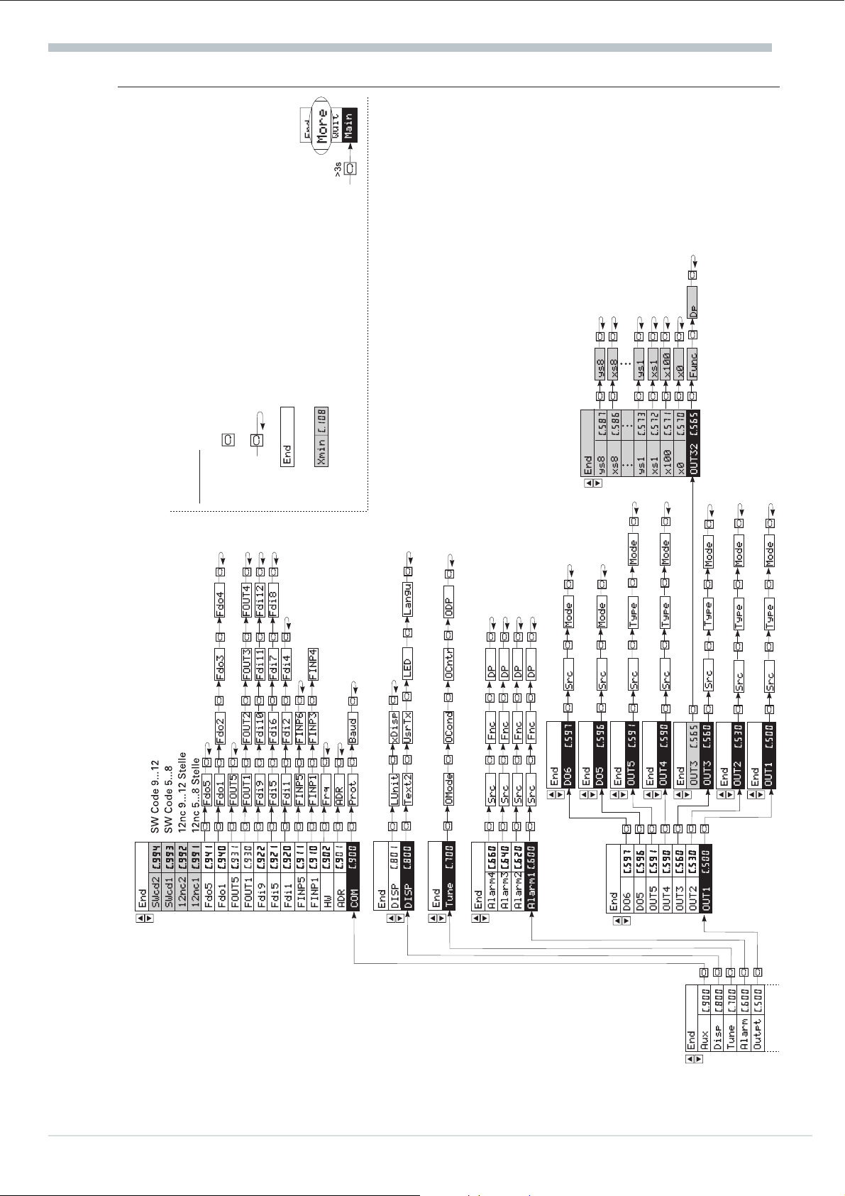
The configuration structure is shown on the two following pages (16 and 17). All possible
configuration words are listed. Configuration words which are irrelevant for a function are not
displayed during the dialogue!
Switch-over to a selection menu is possible from anywhere during configuration by pressing key M >3s.
End: Return to configuration level
More: Activating the More function
Quit: Return to operating level
(configuration changes are not effective)
Exit: Return to operating level (configuration
changes are effective and the controller
is re-initialized).
15 Operating instruction KS94
Page 14
Configuration
Fig.1: Configuration-Overview
Selector key:
Key for selection of menu item, input value and input
position
Acknowledgement and returnto menu item
Return to the previous selection menu is by
acknowledgement and End.
All configuration data shown with gray
background on the drawing are only
accessible after selection of the More
function.
Legend:
Operating instruction KS94 16
Page 15

Fig.2: Configuration-Overview
Configuration
17 Operating instruction KS94
Page 16

Configuration
10.3 Main groups
The following main configuration groups are available for KS9x controller configuration:
Contr
Sourc
Input
Outpt
Alarm
Tune
Disp
Aux
The main configuration groups are structured in a hierarchical order, whereby determination of a
dialogue for prompting only the really relevant configurations is possible.
ENGINEERING TOOL ‘ET/KS 94’
g
Engineering Tool ET/KS94 permits realization of all operations which are possible via the KS94
front panel on a PC, whereby controller configuration and parameter setting are facilitated
considerably.
Controller function
Input allocation
Input function
Output function
Alarm function
Self-tuning
User interface
Additional function
C.100
C.180
C.200
C.500
C.600
C.700
C.800
C.900
...
...
...
...
...
...
C.139
C.192
C.487
C.597
C.660
C.994
Ä page 19
Ä page 21
Ä page 23
Ä page 27
Ä page 31
Ä page 32
Ä page 32
Ä page 33
The engineering tool offers the following functions:
q
q
q
q
q
Connection of PC and KS94 controller is via an RS232/TTL adaptor cable, which must be ordered
separately (ordering information r see page 43 section 12 ). In conjunction with the ‘SIM/KS 94’
controller simulation, a graphic trend display of the real process data is available!
Operating instruction KS94 18
Creation and modification of the parameter set
Transmission of a parameter set to KS94
Read-out of a parameter set from a KS94
Long-term storage of various parameter sets on hard disk or floppy
Display of operating data
Page 17

10.4 CONTR: Controller
This main group determines the controller structure and function, which is used as starting point for
controller configuration for a particular application. The main controller configuration C.100 leads to
an input and output pre-adjustment (C.180.. C.190, C.500.. C591). This ‘proposal’ must always be
checked before commissioning and corrected, if necessary. After determination of this word, no
further settings are required for a large number of applications. Additional function adaptions are
possible via configuration words C.105 and the following configurations.
Main controller configuration 1:
CFunc CType WFunc
(Control behaviour) (Controller type) (Set-point function)
00: signaller 1 output
01: signaller 2 outputs
02: 2-pnt.controller
03: 3-pnt.controller
(heating switching and cooling switching)
04: 3-pnt.controller
(heating continuous and cooling switching)
05: 3-pnt.controller
(heating switching and cooling continuous)
06: {/Y-off
07: 3-pnt.stepping
08: 3-pnt.stepping with Yp (INP6)
09: continuous with position controler
10: continuous
11: continuous split-range
(only with Optin C; OUT1 and OUT3)
12: continuous with current feedback via Yp (INP6)
0: standard controller
1: ratio controller
(Ä C.107)
2: 3-element controller
x
= x1+aw(x2-x3)
eff
3: mean value
x
= (1-b)wx1+bwx2
eff
Configuration
0: set-point
1: set-point / cascade
2: programmer
3: set-point with ext. offset
4: set-point / cascade with
internal offset
5: set-point / cascade with
external offset
6: programmer with
internal offset
7: programmer with
external offset
Main controller configuration 2:
CMode CDiff CFail
(Output action) (Differentiation) (Controller behaviour with main variable sensor break)
0: inverse
1: direct
0: differentiate Xw
1: differentiate X
0: neutral (controller outputs switched off)
1: Ypid = Ymin (0)
2: Ypid = Ymax (100)
3: Ypid = Y2 (adjustment via front panel not possible)
4: Ypid = Y2 (adjustment via front panel possible)
19 Operating instruction KS94
Page 18

Configuration
More
00: no
01: X+Z in conjunction with the process value without differentiation
02: X+-dZ/dt in conjunction with the process value with differentiation
in both directions
03: X+dZ/dt in conjunction with the process value with differentiation
and positive change
04: X-dZ/dt in conjunction with the process value with differentiation
and negative change
05: Y+Z in conjunction with the correcting variable without
differentiation
06: Y+-dZ/dt in conjunction with the correcting variable with
differentiation in both directions
07: Y+dZ/dt in conjunction with the correcting variable with
differentiation and positive change
08: Y-dZ/dt in conjunction with the correcting variable with
differentiation and negative change
Use of an auxiliary variable and external y limiting:
CAux COVC
(Auxiliary variable z via INP3/6) (Output limiting)
0: no external limiting
1: OVC+
2: OVC-
Set-point functions:
(only with option C, Wext and not with 3-element controller)
More
C.106
CON1
Reglerzusatz 2
0.0.0.0
WTrac dW W Sel
(Behaviour of Wint when switching over from Wext to
Wint with the w tracking input switched on )
0: Set-point tracking
1: Process value tracking
Ratio functions: (only with ratio controller)
More
C.107
CON1
Reglerzusatz 3
1.00.2
Ratio XDp
(Ratio control function) (Process value decimal point)
1: (x1 + N0) / x2
2: (x1 + N0) / (x1 + x2)
3: (x2-x1+N0)/x2
0: no digit behind decimal point
1: 1 digit behind decimal point
2: 2 digits behind decimal point
3: 3 digits behind decimal point
(Type of set-point
tracking.)
0: additive
1: factor
(MIN/MAX selection)
0: no selection
1: Max selection Weff
2: Min selection Weff
Operating instruction KS94 20
Page 19
More MoreMore More
Configuration
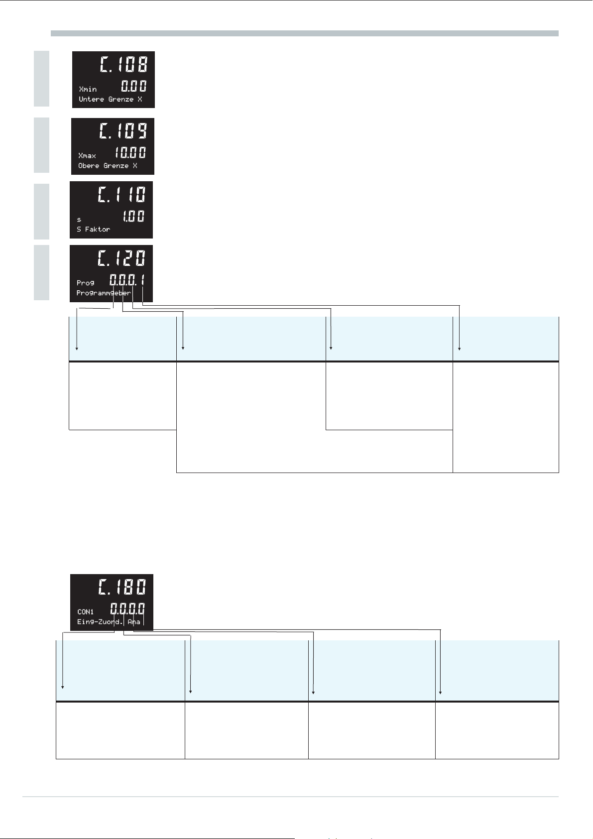
Span start X0: (only with ratio controller)
Xmin:(min. process value limiting Xmin)
Numeric value: -999 ... 9999
Span end X100: (only with ratio controller)
Xmax:(max. process value limiting Xmax)
Numeric value: -999 ... 9999 and Xmin Xmax
Factor for stoichiometric ratio s: (only with ratio controller)
S:stoichiometric ratio
Numeric value: 00.00 ... 99.99 (2 fixed digits behind decimal point)
Programmer configuration:
(only with programmer configured)
PSel PwrUp PEnd PStrt
(Source for program
selection)
0: program selection
via operation
1: program selection
via control input
*C.190; SWi/e select the source for int/ext-switching.
(Behaviour with mains
recovery)
0: continue program
1: stop program and switch over
to Wint
2: continue program after
automatic research
3: continue program after successful automatic research
otherwise switch over to Wint
4: continue program at the time mark of mains recovery
10.5 SOURCE: Input signal allocation
Input signal allocation is dependent of main controller configuration ‘C.100‘. this proposal must
always be checked before commissioning and corrected, if necessary. Therefore, input signal
allocation ‘SOURCE’ is no independent main item and considered as additional configuration of
‘CONTR’.
Signal allocation analog signals:
(Behaviour with
program end)
0: continue with following
program
1: following program and
reset (start required)
(Source for
Run/Stop)
0: start/stop and
reset together*.
control with
int/ext (without
Option B)
1: start/stop and
reset separate.
(Option B)
S X2 SWext S dW S Z
(Signal source for X2
with ratio and
three-element controller)
0: X2 switched off
1: X2 of INP5
2: X2 of INP3
(Signal source for Wext
with controller with
external set-point)
0: Wext switched off
1: Wext of INP5
2: Wext of INP6
3: Wext of INP4
21 Operating instruction KS94
(Signal source for W
with controller with
set-point offset
0: dW switched off
1: dW of INP5
2: dW of INP6
3: dW of INP4
(Signal source for
auxiliary variable)
0: z switched off
1: z of INP3
2: z of INP6
3: z of INP4
Page 20

Configuration
Allocation of digital signals for set-point processing:
SWi/e STrac SdWon Sw/W2
(Set-point switch-over
from internal to external)
0: only internal set-point
1: W/Wext via front
2: di1=external set-point
3: di2=external set-point
4: di1= internal set-point
5: di2= internal set-point
Allocation of digital signals for the controller functions:
S A/M SPI/P SY2on SCoff
(Automatic / manual
(manual switch-over)
0: auto/manual via front
1: fixed to manual
2: di1 = manual
3: di2 = manual
4: Backup run
5: di1 = auto
6: di2 = auto
(Bumpless switch-over
to int. set-point with
1)
int./ext. switch-over )
0: no tracking
2)
1: tracking on
2: di2 = tracking on
3: di12 = tracking on
4: di2 = tracking off
5: di12 = tracking off
(3.pnt.stepping controller:
feedback off, otherwise
PI / P switch-over)
0: PI fixed
2)
1: fixed to P action
2: di1 = P action
3: di2 = P action
4: di1 = PI action
5: di2 = PI action
(Effective set-point
offset)
0: no offset
2)
1: offset on
2: di1 = offset on
3: di2 = offset on
4: di11 = offset on
5: di1 = offset off
6: di2 = offset off
7: di11 = offset off
(Output of safe
correcting value)
0: Y no Y2)
2)
1: fixed to Y2
2: di1 = Y2
3: di2 = Y2
4: timer = Y2
5: di1 = Y
6: di2 = Y
(Switch-over to
set-point w2)
0: no W2
2)
1: fixed to W2
2: di1 = W2
3: di2 = W2
4: di12 = W2
5: Timer = W2
6: di1 = W
7: di2 = W
8: di12 = W
(Switch-off controller)
0: controller on/off via
front (W = ‘——’)
1: controller fixed to off
2: di1 = controller off
3: di2 = controller off
4: timer= controller off
5: di1= controller on
6: di2= controller on
Allocation of digital signals for the programmer:
(only with programmer configured)
More
SPrSt
(Signal source for programmer run/stop)
0: Run/Stop: Front
1: Run/Stop: di4
2: Run/Stop: di4 and timer 1
1) With the programmer configured, switch-over is between internal and external program set-point.
2) Can be switched over via interfaces (e.g. engineering tool; operating data)
Operating instruction KS94 22
Page 21

10.6 INPUT: inputs
The signal inputs for the previously selected controller configuration are determined in this main
group. The signal inputs required for the selected controller function are displayed in the menu for
configuration. As during control function configuration, a large number of applications can also be
covered by determining the main configuration. At the second level, special cases can be matched and
adjusted by additional, optional configuration.Max. 5 signal inputs are provided on KS94. Analog
inputs INP1, INP5 and INP6 are always provided; INP3 and INP4 are optional inputs.
All analog inputs (whether or not used for control) can be used for monitoring purposes
(e.g. alarm processing).
10.6.1 Signal input 1 / INP1 (main variable x1)
Configuration is for main variable x1. This signal input is a universal input for which extensive
functions can be configured.
Main configuration:
The main configuration word is used for determination of input sensor type and
physical unit. Additional input configurations can be determined using the
additional configuration.
Configuration
Type Unit Dp
(Sensor type) (Unit)* (Number of decimals)
Thermocouple:
00: Type L 0 ... 900 °C
01: Type J 0 ... 900 °C
02: Type K 0 ... 1350 °C
03: Type N 0 ... 1300 °C
04: Type S 0 ... 1760 °C
05: Type R 0 ... 1760 °C
06: Type T 0 ... 400 °C
07: Type W 0 ... 2300°C
08: Type E 0 ... 900 °C
09: Type B ( 0) ... 400
...1820°C
* Unit settings for scaling of Typ 00...26. With Typ 30...40 the value is fixed to 0. For this case the unit to be displayed will be configured by C.801.
x0:
(physical value at 0%)
numeric value -999 ... 9999
select only with type = 30 ... 40
Resistance thermometer:
20: Pt 100 -99.9 ... 850.0 °C
21: Pt 100 -99.9 ... 250.0 °C
25: 2 x Pt 100 -99.9 ... 850.0
°C
26: 2 x Pt 100 -99.9 ... 250.0
°C
Standard signals:
30: 0 ... 20 mA
31: 4 ... 20 mA
32: 0 ... 10 V
33: 2 ... 10 V
Potentiometric transducer:
40: 0 ... 500 Ohm
0: at
30...40
1: °C
2: °F
Typ
0: no decimal point
1: 1 digit behind the
decimal point
2: 2 digits behind the
decimal point
3: 3 digits behind decimal point
only with type: 20 ... 40
x100:
(physical value at 100%)
numeric value -999 ... 9999 , X0≠X100!
select only with type = 30 ... 40
23 Operating instruction KS94
Page 22

Configuration
Additional configuration:
Via the additional configuration, the default setting for the signal input can be
changed or matched dependent of sensor type class.
Fail STk XKorr
(Signal behaviour with
sensor fault)
1: upscale(X100)
2: downscale(X0)
3: XFail (C.213)
Type: 00...26, 31, 40 type: 00 ... 09
Non-selectable digits are marked by ‘0’
0: not effective
1: internal TC
2: external TC
Tkref:
(external TC)
numeric value:-99 ... 100 °C or °F
select only with type: 00...08 and STk = 2
XFail:
(substitute value with sensor error)
numeric value: -999 ... 9999
(Temperature
compensation)
(TC fixed in C.210!)
(Process value correction enable)
0: not effective
1: with process value correction (adjustable via
parameters x1in,x1out,x2in,x2out)
Tfm:
(filter time constant for input value processing)
numeric value: 0.0 ... 999.9
Optional configuration 1:
The optional configuration can be used to determine the functions
for two signal pre-processing levels.
Func1, Func2 LDp
(Function selection for signal pre-processing) (decimal point for gain, Xeff and yki)
0: no function, signal is output directly
1: scaling (parameters: m,b)
2: linearization (segment points xs1,ys1 ...)
3: filter (parameter: Tf)
4: square root extraction with factor (parameter:gain)
0: no decimal point
1: 1 digit behind the decimal point
2: 2 digits behind the decimal point
3: 3 digits behind decimal point
Operating instruction KS94 24
Page 23
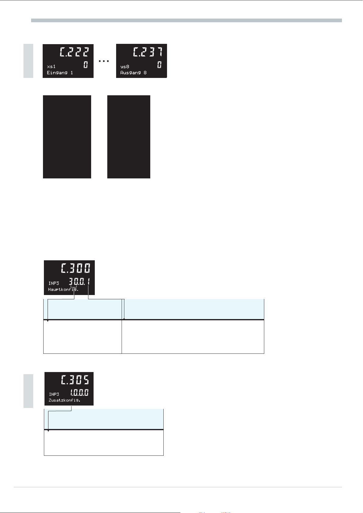
Linearization parameters:
More
The configuration parameters for linearization are stored as follows.
Configuration
C.222 xs1 C.223 ys1
C.224 xs2 C.225 ys2
C.226 xs3 C.227 ys3
C.228 xs4 C.229 ys4
C.230 xs5 C.231 ys5
C.232 xs6 C.233 ys6
C.234 xs7 C.235 ys7
C.236 xs8 C.237 ys8
The range for these configuration words is within -999 and 9999 or ‘——’ (switched off)!
For limiting the number of parameters, these functions can be used only once during pre-processing levels
g
1 or 2! Linearization segment points which are not required can be switched off by setting ‘——‘.
value pair 1
value pair 2
value pair 3
value pair 4
value pair 5
value pair 6
value pair 7
value pair 8
a
Note that the input values
(x-values) must be entered in
ascending order.
(xs1<xs2<xs3...)
10.6.2 Signal input 3 / INP3 (ratio variable x2 or auxiliary variable z)
In this case, the signal is configured for ratio variable x2 or auxiliary variable z, provided that option
p.c.b. C is fitted in the controller and the function was selected during controller configuration.
Main configuration:
Selection is only possible with option p.c.b. C provided.
(Sensor type) (Number of digits behind the decimal point)
Standard signals:
30: 0 ... 20 mA
31: 4 ... 20 mA
More
(Signal behaviour with sensor error)
1: upscale (X100)
2: downscale (X0)
3: XFail (C.313)
Type Dp
0: no decimal point
1: 1 digit behind the decimal point
2: 2 digits behind the decimal point
3: 3 digits behind decimal point
Additional configuration:
The additional configuration can be used for changing or matching the signal
input default setting for the sensor type.
Select only with type = 31 option p.c.b. C and ratio or auxiliary variable selected.
Fail
25 Operating instruction KS94
Page 24

Configuration
The other configuration words for INP3 are explained in section (see following table).
C.301
X0
C.302
X100
C.313
XFail
C.314
Tfm
optional configuration 1
C.320
10.6.3 Signal input 4 / INP4 (variable x3, ext. set-point Wext, override control ovc+/-)
The signal for three-element variable x3 or the galvanically isolated external set-point Wext or
the override control signal ovc+/- are configured with option p.c.b. C fitted in the controller
and the function selected during controller configuration.
The configuration words for INP4 are explained in section and (see following table).
Main configuration
Additional configuration
Optional configuration 1
Optional configuration 2
Linearization table
C.350
C.351
X0
C.352
X100
C.355
C.363
XFail
C.364
Tfm
C.370
C.371
C.372
.. ..
C.387 C.237
see
„
„
„
„
see
„
„
„
„
„
„
„
„
C.201
C.202
C.213
C.214
C.220
C.300
C.201
C.202
C.305
C.213
C.214
C.220
C.221
C.222
without linearization (Func1/2: 2)
10.6.4 Signal input 5 / INP5 (ratio variable x2, ext. set-point Wext)
The signal for ratio variable x2 or external set-point Wext is configured with option p.c.b. not fitted in
the controller and the function selected during controller configuration. The configuration words for
INP5 are explained in section and (see following table).
Main configuration
X0
X100
Additional configuration
XFail
Tfm
Optional configuration 1
C.400
C.401
C.402
C.405
C.413
C.414
C.420
see
„
„
„
„
„
„
C.300
C.201
C.202
C.305
C.213
C.214
C.220
additional 0/2...10V (type: 32/33)
without linearization (Func1/2: 2)
10.6.5 Signal input 6 / INP6 (auxiliary variable Yp, feedback Yp)
The signal for the auxiliary variable Yp or for the position feedbackk is configured, if this was
selected during controller configuration.
The configuration words for INP6 are explained in section and (see following table).
Main configuration
X0
X100
Additional configuration
XFail
Tfm
Optional configuration 1
C.450
C.451
C.452
C.455
C.463
C.464
C.470
see
„
„
„
„
„
„
C.300
C.201
C.202
C.305
C.213
C.214
C.220
additional potentiometric transducer for Yp (type: 40)
without linearisierung (Func1/2: 2)
Operating instruction KS94 26
Page 25

10.7 OUTPT: outputs
10.7.1 Signal output 1 / OUT1
Used for configuring the source of output OUT1. This signal output is a universal
output which can be configured for extensive functions.
Main configuration:
Src Type Mode
(Signal source) (Output stage) (Motor actuator output action)
00: output switched of
01: controller output Y1/Yout1
02: controller output Y2/Yout2
03: output Ypid
04: position feedback Yp
05: controlling deviation Xw
10: process value Xeff
11: X1
12: X2
13: X3
20: set-point W
21: external set-point Wext
22: external offset dWe
23: set-point Weff
24: programmer set-point Wprg
25: alarm 1 (limit1)
26: alarm 2 (limit2)
27: alarm3 (limit3)
28: alarm 1 (limit4)
0: relay (switching)
1: 0 ... 20 mA (continuous output)
2: 4 ... 20 mA (continuous output)
3: 0 / 20 mA (logic)
Configuration
0: not selectable
1: direct / normally open
2: inverse / normally closed
Additional configuration Out1:
Via the options configuration, the functionality for a signal post-processing stage
C.505
OUT1 0.0.0.0
More
Zusatzkonfig.
(Function selection for signal
output processing)
0: no function, signal is output
without change (0%...100%)
1: scaling (reference values C.510
and C.511 are effective)
C.510
x0
Bezugswert 0%
C.511
x100
Bezugswert 100%
100
can be determined.
This configuration word is displayed only with the option enabled.
Func Dp
X0:
(physical value at 0%)
Numeric value -999 ... 9999
0
x100:
(physical value at 0%)
Numeric value -999 ... 9999
(decimal point for xsi,x0,x100)
0: no decimal point
1: 1 digit behind decimal point
2: 2 digits behind decimal point
3: 3 digits behind decimal point
27 Operating instruction KS94
Page 26

Configuration
10.7.2 Signal output 2 / OUT2
Used for configuring the source of output OUT2. This signal output is a universal output and can be
configured for extensive functions.
Main configuration:
Src Type Mode
(Signal source) (Output stage) (Motor actuator output action)
00: output switched off
01: controller output Y1/Yout1
02: controller output Y2/Yout2
25: alarm1 (limit1)
26: alarm2 (limit2)
27: alarm3 (limit3)
28: alarm4 (limit4)
10.7.3 Signal output 3 / OUT3
0: relay (switching) 0: not selectable
1: direct / normally open
2: inverse / normally closed
Used for configuring the source of output OUT3. This signal output is a universal
C.560
OUT3
Hauptkonfig.
00: none (output switched off)
01: controller output Y1/Yout1
02: controller output Y2/Yout2
03: controller output Ypid
04: position feedback Yp
05: control deviation xw
10: process value xeff
11: process value x1
Additional configuration:
The optional configuration can be used for determining the functions for signal post-processing.This
10.1.1
output and can be configured for extensive functions.
Main configuration:
Selection is only possible with option C fitted.
Src Type Mode
(Signal source) (Output stage)
12: process value x2
13: process value x3
20: set-point Wint
21: ext. set-point Wext
22: ext. Offset dWe
23: set-point Weff
24: programmer Wprg
configuration word is displayed only with the option enabled.
0: switched off
1: 0 ... 20 mA
(continuous
output)
2: 4 ... 20 mA
(continuous
output)
3: 0 / 20 mA (logic)
(Motor actuator output
0: not selectable
1: direct / normally open
2: inverse / normally closed
action)
C.565
OUT3
More
Zusatzkonfig.
0: no function, signal is output directly (0%...100%)
1: scaling (reference values C.570 and C.571 are effective)
2: linearization (segment points xs1,ys1 ...)
Operating instruction KS94 28
1.0.0.0
Func Dp
(Function selection for signal output processing) (decimal point for xsi,x0,x100)
0: no decimal point
1: 1 digit behind the decimal point
2: 2 digits behind the decimal point
3: 3 digits behind decimal point
Page 27

a
x0:
(physical value at 0%)
numeric value -999 ... 9999
x100:
(physical value at 100%)
numeric value -999 ... 9999
Note that the input values (x-values)
must be entered in ascending order.
(xs1<xs2<xs3...)
Configuration
The configuration parameters for linearization are stored as
follows.
C.572 xs1 C.573 ys1
C.574 xs2 C.575 ys2
C.576 xs3 C.577 ys3
C.578 xs4 C.579 ys4
C.580 xs5 C.581 ys5
C.582 xs6 C.583 ys6
C.584 xs7 C.585 ys7
C.586 xs8 C.587 ys8
value pair 1
value pair 2
value pair 3
value pair 4
value pair 5
value pair 6
value pair 7
value pair 8
10.7.4 Signal output 4 / OUT4
Used for configuring the source of output OUT4. This signal output can be
configured for extensive functions.
Main configuration:
Src Type Mode
(Signal source) (Output stage) (Actuator output action)
00: output switched off
01: controller output Y1/Yout1
02: controller output Y2/Yout2
25: alarm 1 (limit1)
26: alarm 2 (limit2)
27: alarm 3 (limit3)
28: alarm 4 (limit4)
29: programmer output 1
30: programmer output 2
31: programmer output 3
32: programmer output 4
33: program end
The range for these configuration words is within -999 and
9999 or ‘——’ (switched off)!
0: relay (switching) 0: not selectable
1: direct / normally open
2: inverse / normally closed
29 Operating instruction KS94
Page 28

Configuration
10.7.5 Signal output 5 / OUT5
Used for configuring the source of output OUT1.. This signal output can be configured for extensive
functions.
Main configuration:
Src Type Mode
(Signal source) (Output stage) (Actuator output action)
00: output switched off
01: controller output Y1/Yout1
02: controller output Y2/Yout2
25: alarm 1 (limit1)
26: alarm 2 (limit2)
27: alarm 3 (limit3)
28: alarm 4 (limit4)
29: programmer output 1
30: programmer output 2
31: programmer output 3
32: programmer output 4
33: program end
0: relay (switching) 0: not selectable
1: direct / normally open
2: i nverse / normally closed
10.7.6 DO5,6 (digital control outputs)
Additional digital control outputs are configured!
Main configuration:
(digital control signal DO5)
Selection is possible with option C fitted.
Src Mode
(Digital control signal DO5) (Actuator output action)
00: output switched off
01: controller output Y1
34: status automatic=0 / manual=1
Main configuration:
(Digital control signal DO6)
Selection is possible with option C fitted.
0: not selectable
1: direct / normally open
2: inverse / normally closed
Src Mode
(Digital control signal DO6)
00: output switched off
02: controller output Y2
35: status external=0 / internal=1
Operating instruction KS94 30
(Motor actuator output
0: not selectable
1: direct / normally open
2: inverse / normally closed
action)
Page 29

10.8 ALARM: alarms
10.8.1 Alarm 1 / (limit 1)
The function for alarm 1, (output via output OUT 4) is configured.
Configuration
C.600
ALRM1
Alarm 1
00: no source
01: Xeff
02: Xw*
03: x1
04: x2
05: x3
06: auxiliary
variable z
07: Wext
08: {w
09: Weff
10: Yp
*Limit comparator (refered to set-point), all other versions are fitted with limit contact.
00.0.0
(Alarm signal source) (Alarm function)
Main configuration:
Src Fnc Dp
(Decimals for alarm
11: Ypid
12: OVC
13: WMIN/MAX (Wsel)
14: INP1
16: INP3
17: INP4
18: INP5
19: INP6
20: program time (net)
21: program time (gross)
22: program rest time
23: Status PROFIBUS-DP
24: faulty actor
0: no alarm (don’t care)
1: sensor fail
2: sensor fail or measurement
value alarm
3: sensor fail or measurement
value
alarm with suppression with
set-point switch-over or
start-up
4: measurement value alarm
5: measurement value alarm with
suppression with set-point
change
or start-up
6: Bus error (PROFIBUS-DP)
0: no decimal point
1: 1 digit behind the
decimal point
2: 2 digits behind the
decimal point
3: 3 digits behind the
decimal point
limits)
10.8.2 Alarm 2 (limit 2)
The function for alarm 2 (output via OUT 5) is configured.
Main configuration
10.8.3 Alarm 3 (limit 3)
The function for alarm 3 (output via OUT 1) is configured.
Main configuration
Selection is possible with OUT1 configured as alarm output.
10.8.4 Alarm 4 (limit 4)
The function for alarm 4 (output via OUT 2) is configured.
Main configuration
Selection is possible only with OUT2 configured as alarm output
C.620
C.640
C.660
see
see
see
C.600
C.600
C.600
4 31 Operating instruction KS9
Page 30

Configuration
10.9 TUNE:self-tuning
The type of controller self-tuning and the type of controlled self-tuning can be
adjusted!
Main configuration:
OMode OCond OCntr ODP
(Controller
self-tuning)
0: Standard 0: grad = 0
10.10 DISP: User interface for operation
(Process-at-rest mode) (Controlled self-tuning mode)
1: grad < 0
with inverse controller
or grad > 0
with direct controller
2: grad≠0
0: no function
1: selectable control / disturbance behaviour
2: switch-over via operation
3: switch-over via control input
4: switch-over controlled by Weff
5: switch-over controlled by Xeff
6: switch-over controlled by Ypid
7: switch-over controlled by X-W
(Decimals for
OCntr)
0: no decimal point
1: 1 digit behind
the decimal point
2: 2 digits behind
the decimal point
3: 3 digits behind
the decimal point
Configuration of display function signification via front panel
L1 process operation:
Text2 UsrTx LED Langu
(Signification of display text2)
0: Y (correcting variable display)
bargraph (-100% ...) 0% ...+100%
1: Xw (control deviation) bargraph
-10% ... 0% ... +10% span
2: Tprog bargraph (elapsed
program time) 0 ... tmax
3: Status display
Unit display:
(User text
selection)
0: no user text
1: user text via
control input
2: user text via
function
statuses
(Front LED function)
0: logic output levels
Y1,Y2,LIM1,LIM2
1: logic output levels LIM1...LIM4
2: programmer control outputs D1 ... D4
3: logic output levels LIM1,Y1, Y2, LIM2
4: PROFIBUS-DP errors
5: logic output levels Y2, Y1, LIM1, LIM2
6: logic output levels LIM1,Y2, Y1, LIM2
(Language selection
of text displays)
0: German
1: English
2: French
LUnit xDisp wDisp
(Unit selection for text 1) (select process value for disp.) (select set-point for disp.)
00: no unit
01: °C
02: °F
03: %
04: mbar
05: bar
Operating instruction KS94 32
06: t/h
07: m3/h
08: 1/min
99: freely selectable
Engineering toolnecessary
0: Process value =xeff
1: Process value =x1
2: Process value =x2
3: Process value =x3
0: set-point disp. = Standard
1: set-point disp. = Weff
Page 31

10.11 AUX: Additional functions
The interface function and operating frequency for suppression of interference on inputs are
configured.
10.11.1 COM (serial interface)
Mainconfiguration:
C.900
COM
Schnittstelle
0: IS0174 00: not adjustable
*PROFIBUS: automatic baud rate detection
0.03.0
Prot Baud Addr
(Interface protocol) (Baud rate)* (Interface address)
(IS01745, PROFIBUS)
Only with HW option B
01: 2400 Bd
02: 4800 Bd
03: 9600 Bd
04: 19200 Bd
10.11.2 Hardware
The hardware-related functions are configured.
Main configuration:
Operating frequency for suppression of interference on inputs is configured.
Configuration
ISO1745
0 ... 99 (default 0)
PROFIBUS-DP
1...128 (default 128)
Frq (Mains frequency)
0: 50 Hz
1: 60 Hz
10.11.3 Forcing signal input
All configuration for forcing ar only
present by PROFIBUS-DP
FINP1 FINP3 FINP4 FINP5 FINP6
(Forcing input 1) (Forcing input 3) (Forcing input 4) (Forcing input 5) (Forcing input 6)
0: Controller value
1: Forcing
0: Controller value
1: Forcing
10.11.4 Forcing digital input
10.11.5
Fdi1 Fdi2 Fdi4
(Forcing digital input 1) (Forcing digital input 2) (Forcing digital input 4)
0: Controller value
1: Forcing
0: Controller value
1: Forcing
0: Controller value
1: Forcing
0: Controller value
1: Forcing
0: Controller value
1: Forcing
0: Controller value
1: Forcing
4 33 Operating instruction KS9
Page 32

Configuration
(Forcing dig. Eingang 5) (Forcing dig. Eingang 6) (Forcing dig. Eingang 7) (Forcing dig. Eingang 8)
0: Controller value
1: Forcing
(Forcing dig. input 9) (Forcing dig. input 10) (Forcing dig. input 11) (Forcing dig. input 12)
0: Controller value
1: Forcing
Fdi5 Fdi6 Fdi7 Fdi8
0: Controller value
1: Forcing
Fdi9 Fdi10 Fdi11 Fdi12
0: Controller value
1: Forcing
0: Controller value
1: Forcing
0: Controller value
1: Forcing
0: Controller value
1: Forcing
0: Controller value
1: Forcing
10.11.6 Forcing signal output
FOUT1 FOUT2 FOUT3 FOUT4 FOUT5
(Forcing signl.
outp. 1)
0: Controller value
1: Forcing
2: Release signal
(Forcing signl.
outp. 1)
0: Controller value
1: Forcing
2: Release signal
10.11.7 Forcing digital output
Fdo1 Fdo2 Fdo3 Fdo4 Fdo5/6
(Forcing dig.
outp.1)
0: Controller value
1: Forcing
2: Release signal
(Forcing dig.
outp.2)
0: Controller value
1: Forcing
2: Release signal
(Forcing signl.
outp. 1)
0: Controller value
1: Forcing
2: Release signal
(Forcing dig.
outp.3)
0: Controller value
1: Forcing
2: Release signal
(Forcing signl.
outp. 1)
0: Controller value
1: Forcing
2: Release signal
(Forcing dig.
outp.4)
0: Controller value
1: Forcing
2: Release signal
(Forcing signl.
outp. 1)
0: Controller value
1: Forcing
2: Release signal
(Forcing dig.
outp.5/6)
0: Controller value
1: Forcing
2: Release signal
Operating instruction KS94 34
Page 33

10.11.8 Hard-/Software Codenumber
The following configuration dates are not changeable. They show the hardware version
(C.991 u. C.992) and the software version (C.993 u. C.994) of the instrument.
Example: 9407 923 31201 Example: 4012 157 25320
More
10.12 Examples of configuration
Block diagram Configuration, different from default
9407-9x4-xxxxx
INP1
INP5
INP6
INP3
INP4
Continuous controller
1 xw- alarm, 2 process value alarms
9407-9xx-xxxxx
INP1
INP5
INP6
INP3
INP4
2-pnt. controller +
2 process value alarms
9407-9xx-xxxxx
INP1
INP5
INP6
INP3
INP4
3-pnt. stepping controller +
process value alarm
9407-9x4-xxxxx
INP1
INP5
INP6
INP3
INP4
Ratio controller (continuous)
1 xw- alarm, 2 process value alarms
9407-9x4-1x2xx
INP1
INP5
INP6
di4
di5
Programmer (continuous)
1 xw- alarm
9407-9x4-x1xxx
INP1
INP5
INP6
INP3
INP4
Continuous contr. ‘split-range’
1 xw- alarm, 1 process value alarm
x
x Heizen
x AUF
yp
x1
x2
xeff
x
start/stop
reset
x
xw
xw
wp
xw
xw
ZU
Ende
y1
y2
OUT1
OUT2
OUT4
OUT5
OUT3
OUT1
OUT2
OUT4
OUT5
OUT3
OUT1
OUT2
OUT4
OUT5
OUT3
OUT1
OUT2
OUT4
OUT5
OUT3
OUT1
OUT2
OUT4
OUT5
OUT3
OUT1
OUT2
OUT4
OUT5
OUT3
C.100
C.200
C.500
C.530
C.100
C.200
C.500
C.590
C.100
C.200
C.530
C.590
C.100
C.180
C.200
C.500
C.100
C.192
C.200
C.500
C.100
C.200
C.500
C.560
CFunc
CTyp
WFunc
Typ
Src
Src
CFunc
CTyp
WFunc
Typ
Src
Src
CFunc
CTyp
WFunc
Typ
Src
Src
CFunc
CTyp
WFunc
SX2
Typ
Src
CFunc
CTyp
WFunc
SPrSt
Typ
Src
CFunc
CTyp
WFunc
Typ
Src
Src
= 10 (continuous)
= 0 (standard controller)
=0,1,4or5
= sensor type
= 01(controller output y1)
= 28 (alarm 4)
= 02 (2-pnt.controller)
= 0 (standard controller)
=0,1,4or5
= sensor type
= 01(controller output y1)
= 25 (alarm 1)
= 03 (3-pnt.stepping)
= 0 (standard controller)
=0,1,4or5
= sensor type
= 01 (controller output y1)
= 02 (controller output y2)
= 10 (continuous)
= 1 (ratio controller)
=0,1,4or5
= 1 (INP5)
= sensor type
= 01(controller output y1)
= 10 (continuous)
= 1 (standard controller)
= 3 (programmer)
= 1 (di4)
= sensor type
= 01(controller output y1)
= 11 (continuous split-range)
= 1 (standard controller)
=0,1,4or5
= sensor type
= 01(controller output y1)
= 02(controller output y2)
C.590
C.591
C.600
C.660
C.640
C.591
C.660
C.640
C.591
C.620
C.530
C.590
C.591
C.600
C.660
C.640
C.530
C.591
C.600
C.590
C.591
C.600
C.660
Src
Src
Src
Src
Src
Src
Src
Src
Src
Src
Src
Src
Src
Src
Src
Src
Src
Src
Src
Src
Src
Src
Src
Configuration
= 25 (alarm 1)
= 26 (alarm 2)
= 02 (xw-alarm)
= 03 (process value x1)
= 03 (process value x1)
= 26 (alarm 2)
= 03 (process value x1)
= 03 (process value x1)
= 26 (alarm 2)
= 03 (process value x1)
= 28 (xw-alarm)
= 25 (alarm 1)
= 26 (alarm 2)
= 02 (xw-alarm)
= 01 (xeff)
= 03 (process value x1)
= 28 (alarm 4)
= 33 (program end)
= 02 (xw-alarm)
= 25 (alarm 1)
= 26 (alarm 2)
= 02 (xw-alarm)
= 03 (process value x1)
35 Operating instruction KS94
Page 34

Parameters
11. Parameters
11.1 General
This section gives a survey of the KS92/94 parameter data and general hints for parameter handling.
The parameter operation and effect on the controller operation are described with the operating
principle.
The parameter setting dialogue is realized via selector key M and ‘increment’ / ‘decrement’ keys
ID, like at the other operating levels:
Press the selector key to select menu items / input values within one level and to change to the next
w
higher level.
Press the ‘increment’ / ‘decrement’ keys to return to a lower level or to change input values.
w
11.1.1
The controller parameter structure is given on the following page. All
Parameters which are not relevant for a function (configuration-dependent) are not displayed!
A selection menu can be displayed anywhere at parameter level by pressing key M >3s.
End: return to parameter level
Mark: mark the selected parameter for
display at ‘extended’ configuration level.
Exit: return to operating level.
Conf: transition to configuration level.
parameters are listed.
Allocation of parameters to the ‘extended operating level’
Up to 12 parameters can be allocated to the ‘extended operating level’ (see Fig.3: ), whereby the
controller operation is simplified, since changing over to parameter level whenever one of these
parameters must be changed is omitted.
Allocation: select required parameter, press
‘selection’ key M during >3s (Para blinks)
Select Mark with ‘up’ key I and acknowledge with
‘selection’ key M (see Fig.3: ).
Delete: select the required parameter at the extended
operating level, press ’selection’ key M during >3s
(Para blinks) and acknowledge with ’up’ key I.
Fig.3 : selecting a parameter
Select Clear and acknowledge with ‘selection’
key M (see Fig.4: ).
Hold: The Hold function can be used for selecting
a parameter from the extended operating level for
being visible continuously. For this, select the
required parameter at the extended operating level,
press ‘selection’ key M during >3s (Para blinks)
select Hold with ‘up’ key I and confirm with
’selection’ key M (see Fig.4:).
Applications:
w
During optimization, frequent access to defined parameters (Xp1, Xp2, Tn and Tv) is required.
w
During commissioning, limit value ( LimH1, LimH2, ...) or measurement value corrections must be
changed frequently.
w
With the parameter level disabled, access to the selected parameters is possible for the operator.
Deleting a parameter from the ‘extended operating level’ must be done at this level (see Fig.4: )
Operating instruction KS94 36
Fig.4: deleting a parameter
Page 35

Selection menus KS 94 parameters
Parameters
changing a parameter
37 Operating instruction KS94
Page 36

Parameters
11.2 Set-point function
Text 1 Description Range Default
Setpt
LC+
LCW0
W100
W2
Grw+
GrwGrw2
11.3 Time function
Text 1 Description Range
Timer
TS.Y
TS.MD
TS.HM
TE.Y
TE.MD
TE.HM
Set-point parameter
Band width upper limit 0...9999 ‘——’ (switched off)
Band width lower limit 0...9999 ‘——’ (switched off)
lower set-point limit for Weff -999 ... 9999 0
upper set-point limit for Weff -999 ... 9999 100
additional set-point -999 ... 9999 100
set-point gradient plus with W[w/min] 0.01 ... 99.99 ‘——’ (switched off)
set-point gradient minus with W[w/min] 0.01 ... 99.99 ‘——’ (switched off)
set-point gradient with W2[w/min] 0.01 ... 99.99 ‘——’ (switched off)
Timer-parameters
Start value: Year 0...255
Start value: Month and day Month:1...12; Day: 1...31
Start value: Hour and minutes Hour:0...23; Minutes: 0...59
Final value: Year 0...255
Final value: Month and day Month:1...12; Day: 1...31
Final value: Hour and minutes Hour:0...23; Minutes: 0...59
11.4 Programmer functions
Recp1
Analog Digital
Text 1 Description Range Def. Text 1 Description Range Def.
Wmode
Pmode
Pnext
LCLC+
Wp0
TP1
WP1
...
TP20
WP20
Programmer recipe 1
Change mode 0: Ramp 0
Preset mode 0: Segment start 1
Successive program 1..3 or ‘——’ ‘——’
Band width lower limit 0...9999 ‘——’
Band width upper limit 0...9999 ‘——’
Reset value W0 -999...9999 0
Time segment1 0...9999 [min] ‘——’
Set-point segment 1 -999...9999 0
Time segment 20 0...9999 [min] ‘——’
Set-point segment 20 -999...9999 0
1: Step
2: Ramp (Time
priority
1: Program time
D0
Td1
D1
...
Td20
D20
Reset value control output 1..4 0000..1111 0000
Time segment 1 0...9999[min] ‘——’
control output 1..4 for segm. 1 0000..1111 0000
Time segment 20 0...9999[min] ‘——’
control output 1..4 for segm. 20 0000..1111 0000
Recp2
Recp3
Operating instruction KS94 38
see programmer recipe 1
see programmer recipe 1
Page 37

11.5 Alarm function
Text 1 Description Range Default
LIM1
LimL1
LimH1
Lxsd1
LIM2
LimL2
LimH2
Lxsd2
LIM3
LimL3
LimH3
Lxsd3
LIM4
LimL4
LimH4
Lxsd4
Alarm 1
Low limit -999 ... 9999 ‘——’ (switched off)
High limit -999 ... 9999 ‘——’ (switched off)
Switching difference -999 ... 9999 0
Alarm 2
Low limit -999 ... 9999 ‘——’ (switched off)
High limit -999 ... 9999 ‘——’ (switched off)
Switching difference -999 ... 9999 0
Alarm 3
Low limit -999 ... 9999 ‘——’ (switched off)
High limit -999 ... 9999 ‘——’ (switched off)
Switching difference -999 ... 9999 0
Alarm 4
Low limit -999 ... 9999 ‘——’ (switched off)
High limit -999 ... 9999 ‘——’ (switched off)
Switching difference -999 ... 9999 0
Parameters
11.6 Self-tuning
Text 1 Description R/W Range Def.
Tune
YOptm
dYopt
POpt
Trig1
Trig2
Trig3
ORes1
ORes2
Tu1
Vmax1
Kp1
Tu2
Vmax2
Kp2
Optimization
Correcting variable whilst
process at rest
Step width during identification
Parameter set to be optimized
trigger point 1 (set 1i set 2)
trigger point 2 (set 2 i set 3)
trigger point 3 (set 3 i set 4)
Self-tuning result during heating
Self-tuning result during cooling
Delay time heating
Vmax heating
Process amplification heating
Delay time cooling
Vmax cooling
Process amplification cooling
-105 ... 105 0
R/W
5 ... 100 100
R/W
0 ... 3 1
R/W
-999 ... 9999 (Decimal point as configured in C.700; ODP)
R/W
-999 ... 9999 (Decimal point as configured in C.700; ODP)
R/W
-999 ... 9999 (Decimal point as configured in C.700; ODP)
R/W
0: Cancellation (during optimization preparation)
1: Cancellation (wrong output action)
2: Finished (successful optimization; reversal point found)
3: Cancellation (process does not react or is too slow)
4: Cancellation (reversal point found; estimation unsafe)
5: Cancellation (reversal point not found; estimation unsafe)
R
6: Finished (optimization cancelled due to exceeded set-
point risk; reversal point not reached so far;
estimation unsafe)
7: Cancellation (correcting variable too low {Y < 5%)
8: Cancellation (set-point reserve too low)
0 ... 8 (see ORes1)
R
000,0 ... 999,9 s
R
000,0 ... 999,9 /s
R
000,0 ... 999,9
R
000,0 ... 999,9 s
R
000,0 ... 999,9 /s
R
000,0 ... 999,9
R
39 Operating instruction KS94
Page 38

Parameters
11.7 Control algorithm
Text 1 Description Range Default
CPara
Tpuls
Tm
Y2
Ymin
Ymax
Y0
ParNr
Xsd2
LW
Xsd1
Xsh2
Xsh1
Xsh
Set 0
Xp1 0
Xp2 0
Tn1 0
Tv1 0
T1 0
T2 0
Set1
Xp1 1
Xp2 1
Tn1 1
Tv1 1
T1 1
T2 1
Set2
Xp1 2
Xp2 2
Tn1 2
Tv1 2
T1 2
T2 2
Set3
Xp1 3
Xp2 3
Tn1 3
Tv1 3
T1 3
T2 3
Recov
XwOnY
XwOnX
GrwOn
* Decimal point position of adjustment range as for main variable X1.
Controller parameters
Min. pulse length 0.1 ... 999.9 s 0.3
Actuator response time 10 ... 9999 s 30
Additional correcting value -105 ... 105 % 0
Min. correcting variable limiting -105 ... 105 % 0
Max. correcting variable limiting -105 ... 105 % 100
Correcting variable working point -105 ... 105 % 0
Actual parameter set 0 ... 3
Switching difference of additional contact 0.1 ... 999.9 1
Trigger point separation of additional contact -999 ... 9999 0
Switching difference of signaller 0.1 ... 999.9 1
Neutral zone (Xw > 0) 0.0 ... 999.9 % 0
Neutral zone (Xw < 0) 0.0 ... 999.9 % 0
Neutral zone 0.2 ... 999.9 % 0.2
Parameter set 0
Proportional band 1 0.1 ... 999.9 % 100
Proportional band 2 0.1 ... 999.9 % 100
Integral action time 0 ... 9999 s 10
Derivative action time 0 ... 9999 s 10
Duty cycle 1 0.4 ... 999.9 s 5
Duty cycle 2 0.4 ... 999.9 s 5
Parameter set 1
Proportional band 1 0.1 ... 999.9 % 100
Proportional band 2 0.1 ... 999.9 % 100
Integral action time 0 ... 9999 s 10
Derivative action time 0 ... 9999 s 10
Duty cycle 1 0.4 ... 999.9 s 5
Duty cycle 2 0.4 ... 999.9 s 5
Parameter set 2
Proportional band 1 0.1 ... 999.9 % 100
Proportional band 2 0.1 ... 999.9 % 100
Integral action time 0 ... 9999 s 10
Derivative action time 0 ... 9999 s 10
Duty cycle 1 0.4 ... 999.9 s 5
Duty cycle 2 0.4 ... 999.9 s 5
Parameter set 3
Proportional band 1 0.1 ... 999.9 % 100
Proportional band 2 0.1 ... 999.9 % 100
Integral action time 0 ... 9999 s 10
Derivative action time 0 ... 9999 s 10
Duty cycle 1 0.4 ... 999.9 s 5
Duty cycle 2 0.4 ... 999.9 s 5
Rapid Recovery (controller on)
X-W limit value (X-W < XWony Ä Y tracking) 0 ... 9999 * ‘——’
X-W limit value (X-W > XWonx Ä X tracking) 0 ... 9999 * ‘——’
set-point gradient with X tracking active 0,01 ... 99,99 /min ‘——’
Operating instruction KS94 40
Page 39

11.8 Input processing
11.8.1 Process value handling
Text 1 Description Range Default
Istw
Tdz
N0
a
b
Differentiation time constant for z 0 ... 9999 s 10
Zero offset / ratio -999 ... 9999 0
Factor a / 3-element control -999 ... 9999 1
Factor b / mean value control -999 ... 9999 0.5
11.8.2 Signal pre-processing
Text 1 Description Range Default
INP1
X1in
X1out
X2in
X2out
m
b
gain
Tf
INP3
m3
b3
gain3
Tf3
INP4
m4
b4
gain4
Tf4
INP5
m5
b5
gain5
Tf5
INP6
m6
b6
gain6
Tf6
Signal processing for INP1
Measurement value correction -999...9999 0
Measurement value correction -999...9999 0
Meaurement value correction -999...9999 100
Measurement value correction -999...9999 100
Scaling: gradient m 0 ... 9.999 1
Scaling: offset b -999 ... 9999 0
Square root extraction: gain 0 ... 9.999 1
Filter: filter time constant 0 ... 999.9 s 0.5
Signal pre-processing for INP3
Scaling: gradient m 0 ... 9.999 1
Scaling: offset b -999 ... 9999 0
Square root extraction: gain 0 ... 9.999 1
Filter: filter time constant 0 ... 999.9 s 1
Signal processing for INP4
Scaling: gradient m 0 ... 9.999 1
Scaling: offset b -999 ... 9999 0
Square root extraction: gain 0 ... 9.999 1
Filter: filter time constant 0 ... 999.9 s 0.5
Signal processing for INP5
Scaling: gradient m 0 ... 9.999 1
Scaling: offset b -999 ... 9999 0
Square root extraction: gain 0 ... 9.999 1
Filter: filter time constant 0 ... 999.9 s 0.5
Signal processing for INP6
Scaling: gradient m 0 ... 9.999 1
Scaling: offset b -999 ... 9999 0
Square root extraction: gain 0 ... 9.999 1
Filter: filter time constant 0 ... 999.9 s 0.5
Parameters
41 Operating instruction KS94
Page 40

Parameters
11.9 Miscellaneous
Text 1 Description Range Def.
Aux
Fkey
Blck1 EBloc
Blck2 PBloc
11.10 Signals
General
Function of front panel key H. 0: no function
HBloc
CBloc
WBloc
RBloc
OBloc
1: automatic / manual
2: Wext / Wint
extended operating level 0: free 1: blocked 2: blocked by di1 3: blocked by di2
auto/man- key 0: free 1: blocked 2: blocked by di1 3: blocked by di2
controller off 0: free 1: blocked 2: blocked by di1 3: blocked by di2
setpoint 0: free 1: blocked 2: blocked by di1 3: blocked by di2
programmer preset 0: free 1: blocked 2: blocked by di1 3: blocked by di2
programmer run/stop/reset 0: free 1: blocked 2: blocked by di1 3: blocked by di2
selftuning 0: free 1: blocked 2: blocked by di1 3: blocked by di2
1
0
0
0
0
0
0
0
Signl Description Range Def.
Setpt
Wint
Wext
dWext
dW
Wsel
Contr
Y
Yp
xw
x1
x2
x3
z
OVC
xeff
Input
INP1
INP1r
...
INP6
INP6r
Prog
Wp
tBrut
tNet
tRest
PNr
Clock
Setpoint signals
Internal set-point
External set-point
External correction
Set-point offset
Min/max set-point
Controller signals
Correcting value
Position feedback
Control deviation
Main input x1
Auxillary input x2
Auxillary input x3
Auxillary variable
External correcting variable limiting
Effectiv process value
Input signals
Input 1
Raw measure 1
Input 6
Raw measure 6
Programmer signals
Programmer setpoint
Brutto time (inc. all pause times)
Netto time (without pause times)
Rest time
Programmer no.
Current time
-99,9 ... 999,9 0
1 ... 3 1
Operating instruction KS94 42
Page 41

Versions
12. Versions
Basics
Option B
(Interface)
9407 9 999 1
KS 94
KS 94 with supply voltage
90...250 VAC 4 Relais
(OUT1, OUT2, OUT4, OUT5)
Universal version continuous/switching
3 relays and 1 current/logic output (OUT1, OUT2, OUT4, OUT5)
24 VUC 4 Relais
(OUT1, OUT2, OUT4, OUT5)
24 VUC Universal version continuous/switching
3 relays and 1 current/logic output (OUT1, OUT2, OUT4, OUT5)
No interface
TTL interface with 5 control inputs (di3...di7),
4 control outputs (do1...do4)
RS422/485 interface with 5 control inputs (di3...di7),
4 control outputs (do1...do4)
PROFIBUS-DP interface with 5 control inputs (di3...di7),
4 control outputs (do1...do4)
INTERBUS, 5 control-inputs (di3...di7),
4 contol-outputs (do1...do4)
2
3
3
4
7
8
0
1
2
3
4
No additional functions
Option C
(Supplements)
2 additional inputs (INP3, INP4), 1 additional output (OUT3),
5 control-inputs (di8...di12) 2 control-outputs (do5, do6)
1 additional output (OUT3)
Extrafunctions No additional functions
With measurement value correction
With measurement value correction and programmer
Standard (to be configured by the customer)
Preconfiguration
2-point controller
3-point stepping controller
Continuous controller (current output necessary)
3-point controller (Logik/Relais current output necessary)
3-point stepping controller as 3-component controller
(only with additional inputs INP3, INP4)
Continuous controller as 3-component controller
(only with additional inputs INP3, INP4)
Adjustment as desired
0
1
5
0
1
2
0
1
2
3
4
5
6
9
13.
43 Operating instruction KS94
Page 42

13.1 Input and output allocation with pre-configured units
The signal (e.g. X1, Y1, alarms) allocation to the inputs and outputs for the relevant pre-configuration
(factory setting) is given in the following table. Allocation can be altered at any time via front panel
or interface and should be corrected before commissioning, if necessary.
Order numbers and functions for pre-configured units
output)
9407-92(0;3;7)-xxx1x
Two-point controller (relay
Inputs
INP1 X1
INP3 - X2 - X2
INP4 - X3
INP5 X2; Wext; Wd Wext X2; Wext; Wd INP6 auxiliary variable ‘Z’ di1 W/Wext
di2 Auto/man
di3 Local / remote
di4 Programmer start / stop
di5 Programmer reset
di6 Program selection 1
di7 Program selection 2
di8 Selection parameter set 1
di9 Selection parameter set 2
di10 OVC+ (3-pnt. stepping)
di11 OVC- (3-pnt. stepping) w/dW
di12 Tracking
Outputs
OUT1 Y1 - Y1
OUT2 - - Y2 Y1 - Y2 OUT3 Xeff
OUT4 Alarm1 Y2 Alarm1
OUT5 Alarm2
do1 Programmer output 1
do2 Programmer output 2
do3 Programmer output 3
do4 Programmer output 4
do5 Auto/man
do6 W/Wext
output)
9407-92(1;4;8)-xxx1x
Two-point controller (logic
9407-92(0;3;7)-xxx2x
controller
Three-point stepping
controller
Three-point stepping
9407-92(1;4;8)-xxx2x
9407-92(1;4;8)-xxx3x
Continuous controller
9407-92(1;4;8)-xxx4x
(‘heating’ = logic;
3<%-2>-point contr.
‘cooling’ = relay)
9407-92(3;7)-xxx5x
3-element controller
3-pnt. stepping controller;
9407-9X(4;8)-xxx6x
controller
Continuous, 3-element
Operating instruction KS94 44
Page 43

Page 44

9499- 040-44211
2
Subject to alterations without notice © PMA Prozeß- und Maschinen-Automation GmbH
Änderungen vorbehalten P.O.B. 310 229, D-34058 Kassel, Germany
Sours réserve de toutes modifications Printed in Germany 9499 040 44211 (10/2013)
A4 auf A5gefaltet, 2-fach geheftet, SW-Druck Normalpapier weiß 80g/m
 Loading...