

Page 1
Multi Temperaturecontroller KS800
PID
PID
KS800
PID
PID
PID
PID
PID
PID
KS800KS800
PROFIBUS-DP
KS800
KS800
Interface description
PROFIBUS-DP
9499 040 50511
Valid from: 8395
Page 2

SIMATIC
STEP
®
is a registered trademark of Siemens AG
®
is a registered trademark of Siemens AG
®
is a registered trademark of the
PROFIBUS user organization (PNO)
© PMA Prozeß- und Maschinen-Automation GmbH Printed in Germany
All rights reserved. No part of this documentation may be reproduced or published in any form or by
any means without prior written permission
from the copyright owner.
A publication of PMA Prozeß- und Maschinen Automation
Postfach 310229
D-34058 Kassel
Germany
Page 3

Contents
1 General ..................................5
1.1 Scope of delivery . . . . . . . . . . . . . . . . . . . . . . . . . ..........6
2 Hints on operation............................7
2.1 Interface connection . . . . . . . . . . . . . . . ...................7
2.1.1 Installation of cables . . . . . . . . . . . . . . . . . . . ...........7
2.2 Forcing .........................................7
3 Process data ...............................8
3.1 Defined as status byte are: . . . . . . . . . . . . . . ................12
3.2 Status and diagnosis messages . . . . . . . . . . . . ................15
3.3 Disabling mechanism with changes . . . . . . . . . . . ..............15
3.4 Process data transmission . . . . . . . . . . . . . . ................15
3.5 Parameter transmission . . . . . . . . . . . . . . . . . . . . . . ..........16
3.5.1 Message elements . . . . . . . . . . . . . . ................16
3.5.2 General communication structure . . . . . . . . . . . . . . . .......17
3.5.3 Data write sequence . . . . . . . . . . . . . ................17
3.5.4 Data read procedure . . . . . . . . . . . . . ................18
3.6 Examples . . . . . . . . . . . . . . . . . . . . . . . ................18
3.6.1 Function block protocol principles . . . . . . . . . . . . . . . .......18
3.6.2 Individual access . . . . . . . . . . . . . . . ................18
3.6.3 Block access (tens block). . . . . . . . . . . . . ..............19
3.6.4 Block acces (overall block) . . . . . . . . . . . . . . . . . .......19
3.7 Data types. . . . . . . . . . . . . . . . . . . . . . . ................21
4 Quick entrance .............................22
4.1 Quick entrance with S5. . . . . . . . . . . . . . . . . . . . . . ..........22
4.1.1 Example of a test environment: . . . . . . . . . . .............22
4.2 Quick entrance with S7. . . . . . . . . . . . . . . . . . . . . . ..........24
4.2.1 Example of a test environment: . . . . . . . . . . .............24
5 Function block protocol ........................26
5.1 Data structuring. ...................................26
5.2 CODE tables . . . . . . . . . . . . . . . . . . . . . . . . . . . . . ........27
5.2.1 Structure of configuration words (C.xxxx). . . . . . . . . . ........27
5.2.2 INSTRUMENT (FB no.: 0 type no.: 0) . . . . . . . . . . .......27
5.2.3 Special accesses (FB no.: 10 ... 17 type no.: 10) . . . . . . . . . . . . 33
5.2.4 Freely configurable (FB no.: 20 ... 27 type no.: 20) . . . . . . . . . . 34
5.2.5 INPUT (FB no.: 60 ... 67 Type no.: 112) . . . . . . . . . . . . . . . . 36
5.2.6 CONTR (FB no.: 50 ... 57 Type no.: 91) . . . . . . . . . . . . . . . . 37
5.2.7 ALARM (FB no.: 70 ... 77 Type no.: 46) . . . . . . . . . . . . . . . . 41
3 9499 040 50511
Page 4

6 Function modules ...........................43
6.1 Function module for SIMATIC®S5 ........................43
6.1.1 Structure . . . . . . . . . . . . . . . . . . . . ...............43
6.1.2 Function module call . . . . . . . . . . . . . ................45
6.2 Function module for SIMATIC®S7 ........................46
6.2.1 Structure . . . . . . . . . . . . . . . . . . . . ...............46
7 Annex ..................................49
7.1 Terms .........................................49
7.2 GSD file . . . . . . . . . . . . . . . . . . . . . . . ................49
9499 040 50511 4
Page 5

1 General
The KS800 multi-temperature controller versions (9407-480-30001) are equipped with a PROFIBUS-DP
interface for transmission of process parameter and configuration data. Connection is via the 9-pole sub-D
connector socket. The serial communication interface permits connections to supervisory systems,
visualization tools, etc.
Another interface, which is always provided as standard, is the PC interface. This interface serves for
connecting an engineering tool, which runs on a PC.
Communication is according to the master/slave principle. KS800-DP is always slave.
Cable medium as well as physical and electrical interface proporties:
Network topologie
w
Linear bus with active bus termination at both ends. Stub lines are possible (dependent of cable type, a
maximum overall stub line length of 6,6m with 1,5Mbit/s and of 1,6m with 3-12Mbit/s is possible).
Transmission medium
w
screened, twisted 2-wire cable (Ä EN 50170 vol.2).
Baudrates and cable lengths (without repeater)
w
The maximum cable length is dependent of transmission rate.
The Baudrate is determined by the master configuration.
General
Automatic Baudrate
detection
Interface
w
RS485 connectable with sub-D connector (9-pole).
Address settings
w
Address setting is possible as follows:
- Adjustment via coding switches, range 00 ... 99, default 00
- adjustment via software, range 0 ... 126, default 126
With the coding switches set to ‘00’, the adjusted software address is valid.
A modified coding switch address is active only after switching on the supply voltage again.
32 instruments in one segment. Extension to 127 by means of a repeater is possible.
w
KS800 with PROFIBUS-DP interface offers many advantages with respect to handling and integration into a
PROFIBUS network.
Diagnosis and monitoring via COM-LED
w
LED off: error identification for ‘no bus access’ (so far not addressed by the master)
LED on: OK, cyclic data exchange running
LED blinks: (2Hz) Data exchange interrupted
LED blinks: (4Hz) PROFIBUS parameter setting and configuration error.
Particularities
w
Configurable process data modules
Direct input and output reading and writing
Output forcing
Easy connection to PLCs
Baudrate Maximum cable length
9,6 / 19,2 / 93,75 kbit/s 1200 m
187,5 kbit/s 1000 m
500 kbit/s 400 m
1,5 Mbit/s 200 m
3 ... 12 Mbit/s 100m
5 9499 040 50511
Page 6

General
1.1 Scope of delivery
The engineering set comprises:
Disk
w
3,5-Diskette (A:)
Ks800dp
Gsd
S5_fb
Example.fix
S7_fb
Example
Type
Example
Interface description for PROFIBUS-DP
w
Pma_0800.gsd
Pmadp1st.s5d
Pmadm3*.*
Pma_parm.arj
Ks800dmo.arj
Ks800_1x.200
Demo308i.et2
Demo95ui.et2
Ks800dem.et2
GSD file
STEP®5-FB for parameter channel
project example in STEP®5 for FixPoint
STEP®7-FB for parameter channel
project example in STEP®7
type file
configuration example COM PROFIBUS for
IM308-C
configuration example COM PROFIBUS for S5 CPU
95U
configuration example COM PROFIBUS for
PC-Karte
9499 040 50511 6
Page 7
2 Hints on operation
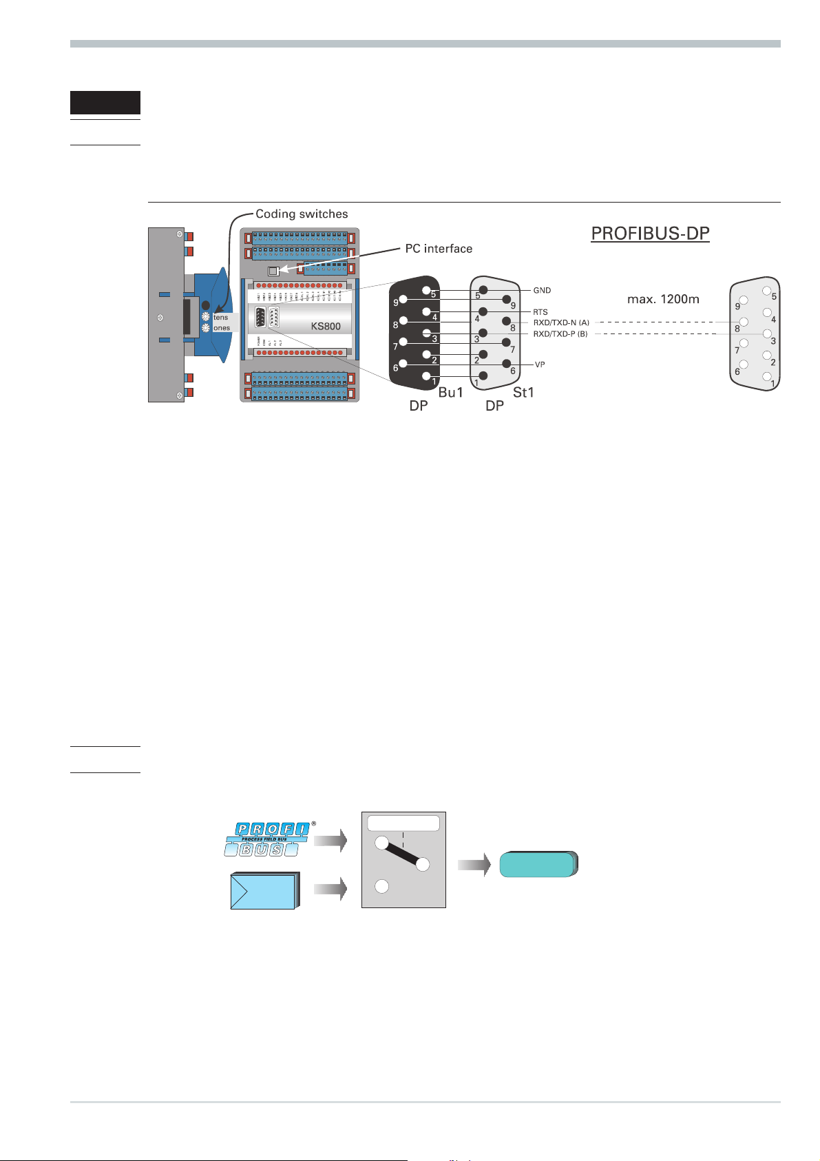
2.1 Interface connection
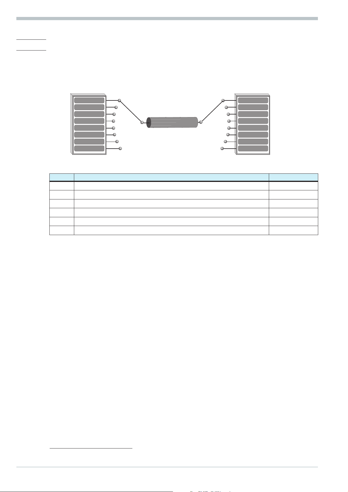
The PROFIBUS must be connected to the 9-pole sub-D socket.
Serial interface, physical RS485-based signals.
Fig.: 1 Connecting PROFIBUS-DP
Hints on operation
The construction of suitable cabling must be provided by the user, whereby the general cable specifications
to EN 50170 vol.2 must be taken into account.
2.1.1 Installation of cables
When laying the cables, the general hints for cable installation given by the supplier of the master module
must be followed:
Cable run in buildings (inside and outside cabinets)
w
Cable run inside and outside buildings
w
Potential compensation
w
Cable screening
w
Measures against interference voltages
w
Stub line length
w
Bus termination resistors are not contained in KS800-DP, but must be realized via the connector, if
w
necessary.
Earthing
w
Special hints for installation of PROFIBUS cables are given in the PNO technical guideline “Installation
g
guidelines for PROFIBUS-DP/FMS” (Order no. 2.111 [dt]; 2.112 [engl.]).
2.2 Forcing
Digital outputs can be written directly after configuring them accordingly.
C.100 C.500/
do
7 9499 040 50511
Page 8
Process data
3 Process data
Process data
module A:
Process data
module B:
Process data
module C:
Process data
module D:
Process data
module E:
Process data
module F:
Process data
module G:
Process data
module H:
During data transmission, distinction of process data to be transmitted cyclically and parameter /
configuration data to be transmitted acyclically is made. The I/O data field is structured modularly for
matching it to the requirements of the control task.
Selection of the process data module is via configuration tools of the master circuits (e.g. with Siemens S5
via COM PROFIBUS).
The following process data modules can be configured:
read (66 bytes)
1)
Instrument status, (process value, output value, status, ..) Instrument control, (set-point, output value, ...)
write1)(52 bytes) without
parameter
channel
read (74 bytes)
Instrument status, (process value, output value, status, ..) Instrument control, (set-point, output value, ...)
1)
write1)(60 bytes)* with
parameter
channel
1)
only parameter channel
read (74 Byte)
1)
Instrument status, (process value, output value,
(8/8 bytes)
write (60 Byte)
1)
Instrument control, (set-point, output value, ...)
with parameter
channel
status, ..)
read (116 Byte)
1)
write (116Byte)
Instrument status, (52 variable process data) Instrument control, (52 variable process data)
read (92 Byte)
1)
write (92 Byte)
Instrument status, (40 variable process data) Instrument control, (40 variable process data)
read (28 Byte)
1)
write (28 Byte)
Instrument status, (8 variable process data) Instrument control, (8 variable process data)
read (16 Byte)
Instrument status, (multiplexing 64 variable
process data)
1)
write (16 Byte)
Instrument control, (multiplexing 64 variable process
data)
1)
with parameter
channel
1)
with parameter
channel
1)
with parameter
channel
1)
with parameter
channel
The parameter channel is used for sequential transmission of parameter and configuration data. The values to
be adjusted and data significations are given in the following tables:
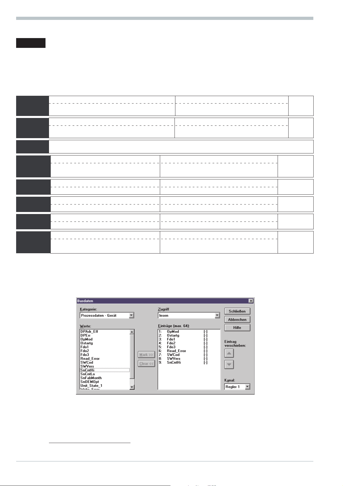
For the process data modules (module E - H), the cyclical transmission data must be selected by means of
the ‘KS800’ engineering tool via General instrument settings r
Communication r Bus data.
Max. 64 data for reading and 64 data for writing can be selected. Dependent of selected process data
module, the first 52 data (module E), the first 40 data (module F), the first 8 data (module H) or all
data are used (module G).
1) Number of required bytes in the I/O field
9499 040 50511 8
Page 9
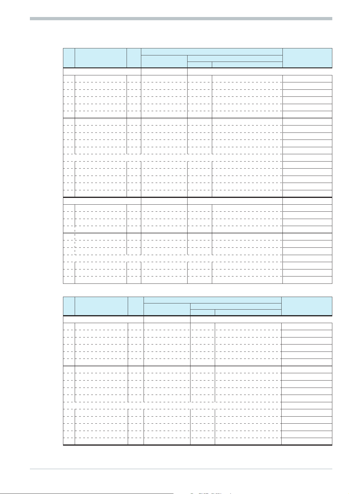
Module A (process data of all 8 channels)
q
FIX point format
No. Descr. R/W
Inputs ] 66
0 Unit_State R 2 11 16DE
1 Xeff_1 R 2 50 1AE
2 Yeff_1 R 2 50 1AE
3 HC_1 R 2 50 1AE
4 Alarm_1 R 1 10 8DE
5 Status_1 R 1 10 8DE
6 Xeff_2 R 2 50 1AE
7 Yeff_2 R 2 50 1AE
8 HC_2 R 2 50 1AE
9 Alarm_2 R 1 10 8DE
10 Status_2 R 1 10 8DE
...
36 Xeff_8 R 2 50 1AE
37 Yeff_8 R 2 50 1AE
38 HC_8 R 2 50 1AE
39 Alarm_8 R 1 10 8DE
40 Status_8 R 1 10 8DE
Outputs ] 52
41 Unit_Cntrl W 4 23 32DA
42 Wvol_1 W 2 60 1AA
43 Yman_1 W 2 60 1AA
44 Cntrl_1 W 2 21 16DA
45 Wvol_2 W 2 60 1AA
46 Yman_2 W 2 60 1AA
47 Cntrl_2 W 2 21 16DA
...
63 Wvol_8 W 2 60 1AA
64 Yman_8 W 2 60 1AA
65 Cntrl_8 W 2 21 16DA
Number of bytes
Hex COM PROFIBUS
Value
Process data
Rem.
A
B
C
B
C
B
C
D
E
E
E
q
Module B (process data of all 8 channels + parameter channel)
FIX point format
No. Descr. R/W
Inputs ] 66
0 Unit_State R 2 11 16DE
1 Xeff_1 R 2 50 1AE
2 Yeff_1 R 2 50 1AE
3 HC_1 R 2 50 1AE
4 Alarm_1 R 1 10 8DE
5 Status_1 R 1 10 8DE
6 Xeff_2 R 2 50 1AE
7 Yeff_2 R 2 50 1AE
8 HC_2 R 2 50 1AE
9 Alarm_2 R 1 10 8DE
10 Status_2 R 1 10 8DE
...
36 Xeff_8 R 2 50 1AE
37 Yeff_8 R 2 50 1AE
38 HC_8 R 2 50 1AE
39 Alarm_8 R 1 10 8DE
40 Status_8 R 1 10 8DE
Number of bytes
Hex COM PROFIBUS
Value
Rem.
A
B
C
B
C
B
C
9 9499 040 50511
Page 10
Process data
Outputs ] 52
41 Unit_Cntrl W 4 23 32DA
42 Wvol_1 W 2 60 1AA
43 Yman_1 W 2 60 1AA
44 Cntrl_1 W 2 21 16DA
45 Wvol_2 W 2 60 1AA
46 Yman_2 W 2 60 1AA
47 Cntrl_2 W 2 21 16DA
...
63 Wvol_8 W 2 60 1AA
64 Yman_8 W 2 60 1AA
65 Cntrl_8 W 2 21 16DA
Inputs/outputs
66 Parameter channel R/W 8 / 8 F3 4AX
Module C (only parameter channels)
q
FIX Point-Format
No. Descr. R/W
Inputs/outputs
0 Parameter channel R/W 8 / 8 F3 4AX
Number of bytes
Hex COM PROFIBUS
Value
D
E
E
E
Transmission of the analog values is in the 16-bit fix point format (FIX). In FIX format, all values are
interpreted with one digit behind the decimal point (range -3000,0 to 3200,0).
Module D (Like Module B, but more compact Configurationformat)
q
FIX Point-Format
No. Descr. R/W
Inputs ] 74
0 Unit_State R 2 11 16DE
1 Xeff_1, Yeff_1, HC_1, Alarm_1, Status_1 R 8 53 4AE
2 Xeff_2, Yeff_2, HC_2, Alarm_2, Status_2 R 8 53 4AE
...
8 Xeff_8, Yeff_8, HC_8, Alarm_8, Status_8 R 8 53 4AE
Outputs ] 60
9 Unit_Cntrl W 4 23 32DA
10 Wvol_1, Yman_1, Cntrl_1 W 6 62 3AA
11 Wvol_2, Yman_2, Cntrl_2 W 6 62 3AA
...
17 Wvol_8, Yman_8, Cntrl_8 W 6 62 3AA
In- /Outputs
18 Parameterchannel R/W 8 / 8 F3 4AX
Number of
Bytes
Hex COM PROFIBUS
Value
Rem.
A
B
9499 040 50511 10
Page 11
Module E (52 variable processdata and parameterchannel)
q
FIX Point-Format
No.. Descr.. R/W
Inputs ] 116
0 Unit_State, Digital_Outputs R 4 13 32DE
1 IN_1 … IN_8 R 16 57 8AE
2 IN_9 … IN_16 R 16 57 8AE
...
6 IN_41 … IN_48 R 16 57 8AE
7 IN_49 … IN_52 R 8 53 4AE
Outputs ] 116
8 Unit_Cntrl I, Unit_Cntrl II W 4 23 32DA
9 OUT_1 … OUT_8 W 16 67 8AA
10 OUT_9 … OUT_16 W 16 67 8AA
...
14 OUT_41 … OUT_48 W 16 67 8AA
15 OUT_49 … OUT_52 W 8 63 4AA
In- /Outputs
16 Parameterchannel R/W 8 / 8 F3 4AX
Number of
Bytes
Hex COM PROFIBUS
Value
Process data
Rem.
A, F
B
Module F (40 variable processdata and parameterchannel)
q
FIX Point-Format
No.. Descr.. R/W
Inputs ] 92
0 Unit_State, Digital_Outputs R 4 13 32DE
1 IN_1 … IN_8 R 16 57 8AE
2 IN_9 … IN_16 R 16 57 8AE
...
5 IN_33 … IN_40 R 16 57 8AE
Outputs ] 92
6 Unit_Cntrl I, Unit_Cntrl II W 4 23 32DA
7 OUT_1 … OUT_8 W 16 67 8AA
8 OUT_9 … OUT_16 W 16 67 8AA
...
11 OUT_33 … OUT_40 W 16 67 8AA
In- /Outputs
12 Parameterchannel R/W 8 / 8 F3 4AX
q
Module G (8 variable processdata and parameterchannel)
No.. Descr.. R/W
Inputs ] 28
0 Unit_State, Digital_Outputs R 4 13 32DE
1 IN_1 … IN_8 R 16 57 8AE
Outputs ] 28
2 Unit_Cntrl I, Unit_Cntrl II W 4 23 32DA
3 OUT_1 … OUT_8 W 16 67 8AA
In- /Outputs
4 Parameterchannel R/W 8 / 8 F3 4AX
Number of
Bytes
Number of
Bytes
Hex COM PROFIBUS
FIX Point-Format
Hex COM PROFIBUS
Value
Value
Rem.
A, F
B
Rem.
A, F
B
11 9499 040 50511
Page 12
Process data
g
Module H (Multiplexing of all 64 variable processdata and parameterchannel)
q
FIX Point-Format
No.. Descr. R/W
Inputs ] 16
0 Unit_State, Digital_Outputs R 4 13 32DE
1
Index IN
2 Read Value R 2 50 1AE
Outputs ] 16
3 Unit_Cntrl I, Unit_Cntrl II W 4 23 32DA
4
Index OUT
5 Write Value W 2 60 1AA
In- /Outputs
6 Parameterchannel R/W 8 / 8 F3 4AX
Operating principle (reading):
Enter the index number into ‘Index OUT’ (Read).
w
After the index number is mirror-inverted in ‘Index IN’ (Read), the read value is stored in
w
‘Read Value’ .
Operating principle (writing):
Enter the index number into ‘Index OUT’ (Write)
w
Enter the value to be written into ‘Write Value’.
w
After the index number is mirror-inverted in ‘Index IN’ (Write), the value was transmitted.
w
To ensure consistent data transmission, ‘Index OUT’ (Write) and ‘Write Value’ must have been updated
safely before a PROFIBUS data cycle. If this cannot be ensured, proceed as follows: ‘0’ in ‘Index OUT’
(Write), write the value to be transmitted into ‘Write Value’ and write the index number into ‘Index OUT’
(Write). With entry ‘0’ in ‘Index OUT’ (Read) / ‘Index OUT’ (Write), no data are transmitted.
Read
Write
Read
Write
Number of
Bytes
R 2 50 1AE
W 2 60 1AA
Hex COM PROFIBUS
Value
Rem.
A, F
B
3.1 Defined as status byte are:
Unit_State
MSB LSB
D15 D14 D13 .. .. D2 D1 D0
Bit no. Name Allocation Status ‘0’ Status ‘1’
D0
D1
D2
D3
D4
D5
D6, D7
D8
D9
D10
D11
D12
D13
D14
D15
IN13 Digital input IN13 (ParNo) off on
IN14 Digital input IN14 (Coff) off on
IN15 Digital input IN15 (Leck) off on
IN16 Digital input IN16 (w/w2) off on
always ‘0’
Dex Changed ComRead or ComWrite data no yes
Always ‘0’
Err1 Transmission error channel 1 no yes
Err2 Transmission error channel 2 no yes
Err3 Transmission error channel 3 no yes
Err4 Transmission error channel 4 no yes
Err5 Transmission error channel 5 no yes
Err6 Transmission error channel 6 no yes
Err7 Transmission error channel 7 no yes
Err8 Transmission error channel 8 no yes
9499 040 50511 12
Page 13

Rem. B1 Alarm_x
MSB LSB
D7 D6 D5 D4 D3 D2 D1 D0
Bit no. Name Allocation Status ‘0’ Status ‘1’
Lim HH Alarm HH off on
D0
Lim H Alarm H off on
D1
Lim L Alarm L off on
D2
Lim LL Alarm LL off on
D3
Fail Alarm Sensor Fail no yes
D4
HCAl Heating current alarm off on
D5
LeckAl Leakage current alarm off on
D6
do1_8Al Alarm OUT1 ... 8 off on
D7
Rem. C Status_x
MSB LSB
D7 D6 D5 D4 D3 D2 D1 D0
Bit no. Name Allocation Status ‘0’ Status ‘1’
w/W2 w/W2 switch-over w W2
D0
We/w External/internal switch-over external internal
D1
w/Wanf Start-up set-point switch-over w Wanf
D2
Orun Optimization active no yes
D3
A/M Automatic/manual switch-over auto manual
D4
Coff Controller switched off no yes
D5
Y1 Switching output 1 off on
D6
Y2 Switching output 2 off on
D7
Rem. D Unit_Contrl I
MSB LSB
D31 D30 D29 ... ... D2 D1 D0
Process data
Bit no. Name Allocation Status ‘0’ Status ‘1’
D0
D1
D2
D3
D4
D5
D6
D7
D8
D9
D10
D11
D12
D13
D14
D15
OUT1 Forcing of output OUT1 off on
OUT2 Forcing of output OUT2 off on
OUT3 Forcing of output OUT3 off on
OUT4 Forcing of output OUT4 off on
OUT5 Forcing of output OUT5 off on
OUT6 Forcing of output OUT6 off on
OUT7 Forcing of output OUT7 off on
OUT8 Forcing of output OUT8 off on
OUT9 Forcing of output OUT9 off on
OUT10 Forcing of output OUT10 off on
OUT11 Forcing of output OUT11 off on
OUT12 Forcing of output OUT12 off on
OUT13 Forcing of output OUT13 off on
OUT14 Forcing of output OUT14 off on
OUT15 Forcing of output OUT15 off on
OUT16 Forcing of output OUT16 off on
13 9499 040 50511
Page 14

Process data
Rem. E Unit_Contrl II
MSB LSB
D31 D30 D29 ... ... D2 D1 D0
Bit no. Name Allocation Status ‘0’ Status ‘1’
D0
D1
D2
D3
D4
D5
D6- D15
OUT17 Forcing of output OUT17 off on
OUT18 Forcing of output OUT18 off on
OUT19 Forcing of output OUT19 off on
OstartG Start optimizing all group controllers no start start
OStopG Forcing of output OUT5 no stop stop
Dval Forcing of output OUT6 flank 0->1
always "0"
Rem. F Cntrl_x
MSB LSB
D15 D14 D13 ... ... D2 D1 D0
Bit no. Name Allocation Status ‘0’ Status ‘1’
D0
D1
D2
D3
D4
D5
D6 .. D15
A/M Automatic/manual switch-over auto manual
Coff Controller switched off no yes
w/W2 w/W2 switch-over w W2
We/w External/internal switch-over external internal
OStart Start optimization
OStop Stop optimization
1)
1)
no start start
no stop stop
unused, always ‘0’
Rem. G Digital_Outputs
MSB LSB
D15 D14 D13 ... ... D2 D1 D0
Bit-No. Name Allocation Status ‘0’ Status ‘1’
D0
D1
D2
D3
D4
D5
D6
D7
D8
D9
D10
D11
D12
D13
D14
D15
Y1_7 Y1-Output Channel 7 off on
Y2_7 Y2-Output Channel s 7 off on
Y1_6 Y1-Output Channel 6 off on
Y2_6 Y2-Output Channel 6 off on
Y1_5 Y1-Output Channel 5 off on
Y2_5 Y2-Output Channel 5 off on
Y1_4 Y1-Output Channel 4 off on
Y2_4 Y2-Output Channel 4 off on
Y1_3 Y1-Output Channel 3 off on
Y2_3 Y2-Output Channel 3 off on
Y1_2 Y1-Output Channel 2 off on
Y2_2 Y2-Output Channel 2 off on
Y1_1 Y1-Output Channel 1 off on
Y2_1 Y2-Output Channel 1 off on
Y1_0 Y1-Output Channel 0 off on
Y2_0 Y2-Output Channel 0 off on
1) Signals are active only with change from 0 Ä 1. The signal must be available, until a change of Orun
(see Status_x) has occurred.
2)See chapter 3.3 page 15 "Disabling mechanism with changes".
9499 040 50511 14
Page 15

3.2 Status and diagnosis messages
For KS800 instrumwent status signalling, the external (user-specific) diagnosis must be used. The format
corresponds to the instrument-related diagnosis (EN50170 volume 2 PROFIBUS).
Instrument-specific diagnosis Octet 1
MSB LSB
D7 D6 D5 D4 D3 D2 D1 D0
Bit no. Name Allocation Status ‘0’ Status ‘1’ Type
D0
D1
D2
D3
D4 .. D7
Instrument-specific diagnosis Octet 2
Bit no. Name Allocation Status ‘0’ Status ‘1’ Type
D0
D1
D2
D3
D4
D5
D6
D7
Online/Conf On-line / configuration on-line configuration status
DO1_12Fail Error do1 ... do12 no yes diagnosis
D=13_16Fail Error do13 ... do16 no yes diagnosis
HCFail Heating current short circuit no yes diagnosis
unused, always ‘0’
MSB LSB
D7 D6 D5 D4 D3 D2 D1 D0
InpF1 Input fail channel 1 no yes diagnosis
InpF2 Input fail channel 2 no yes dianosis
InpF3 Input fail channel 3 no yes diagnosis
InpF4 Input fail channel 4 no yes diagnosis
InpF5 Input fail channel 5 no yes diagnosis
InpF6 Input fail channel 6 no yes diagnosis
InpF7 Input fail channel 7 no yes diagnosis
InpF8 Input fail channel 8 no yes diagnosis
Process data
3.3 Disabling mechanism with changes
Changing the reference to a datum to be transmitted during operation, e.g. on-line via parameter channel
or via the engineering interface, implies a hazard of value misinterpreting by bus master and KS800.
This can be prevented by a disabling mechanism.
When changing a reference, the controller module sets bit Dex = 1.
w
The master must evaluate bit Dex.
w
Acknowledgement and a statement that there are only valid write data also on the master side, are
w
generated via a positive flank for bit Dval.
When receiving a positive flank, the controller module sets Dex = 0 and stores the data which were
w
sent.
Resetting Dex is also possible by switching the voltage off and on again.
w
3.4 Process data transmission
Process data are transmitted cyclically by the controller, whereby compliance with the minimum poll time of
570ms is ensured, if no simultaneous access via the parameter channel is made. Output data sent to KS800
are compared with the previously transmitted values and processed by the controller with deviation. If one of
the data is faulty, bit 8 with error in channel 1, bit 9 with error in channel 2 ... or bit 15 with error in channel
8 is set in the ‘Unit_State’, until no faulty accesses are pending any more.
15 9499 040 50511
Page 16
Process data
3.5 Parameter transmission
For parameter transmission, the ‘parameter channel’ via which data can be exchanged transparently via the
function block protocol is available. Thereby, all possible protocol access modes are supported (individual
access, tens block and overall block). Communication to the controller is transparent, i.e. the user himself is
responsible for monitoring ranges, operating modes (auto/hand) etc.
The parameter channel is designed for large amounts of data with low requirements on the transmission
speed.
3.5.1 Message elements
Some terms which are used in the following text are explained below:
Element Description Rem.
ID
ID1
Code
FB no.
Fct no.
Type
Rem. A ID
This element identifies the telegram type:
Rem. B ID1
This element identifies the file format:
Parameter 1 Parameter 1
Parameter 2 Parameter 2
.... ....
.... ....
.... ....
.... ....
.... ....
Parameter n Parameter n
Parameterkanal
Telegram mode identification
Format of data to be transmitted or to be received
Addressing code of a datum
Function block number
Function number
d.c. (always ‘0’)
ID = 0x10 = start telegram
1)
ID = 0x68 = data telegram
ID = 0x16 = end telegram
ID1=0= Integer
ID1 = 1 = Real value as fixpoint
A
B
C
D
E
Rem. C Code
The code identification is decimal and the range includes ‘00’...’99’ as well as ‘178’ = B2 and ‘179’ = B3.
Rem. D FB no. (function block number)
A function block is addressed with a function block number. It is within ‘0’ and ‘250’. Channel addressing is
also via the function block number.
Function block number ranges:
0general data for the overall instrument
w
1 - 99 fixed function blocks
w
Rem. E Fct. no. (function number)
A function as a partial address of a function block is also addressed with a function number. It is within ‘0’
and ‘99’.
Function number ranges:
0function general
w
1 - 99 other functions
w
1) 0x10 means 10 in hexadecimal
9499 040 50511 16
Page 17

3.5.2 General communication structure
For transmission of the parameters required for the function block protocol via an 8-byte data window, the
access is composed of three parts:
Order header with specification of code, FB no., fct. no., type and the following real and integer values.
w
Start telegram structure:
Byte 0 Byte 1 Byte 2 Byte 3 Byte 4 Byte 5 Byte 6 Byte 7
ID ID1 Code FB no. Fct._no. Type Numb.real values Numb.integer values
n data blocks with the data to be transmitted
w
Data telegram structure:
Transmission of real data as fixedpoint and of integer values
Byte 0 Byte 1 Byte 2 Byte 3 Byte 4 Byte 5 Byte 6 Byte 7
ID Count Integer
An end block provides the operation result
w
Structure of the end telegram:
Byte 0 Byte 1 Byte 2 Byte 3 Byte 4 Byte 5 Byte 6 Byte 7
ID Result
Signification of result
0OK
4 NAK
The read or write operation is always started by the master. With the number of real and integer values≠0, a
write service, otherwise, a read service is started.
The code determines the access type:
Code < 100, no multiple of 10 Ä individual access
Code < 100, multiple of 10 Ä tens block access
Code > 100 Ä overall block access
Process data
3.5.3 Data write sequence
Start telegram:
Master sends: Byte 0 Byte 1 Byte 2 Byte 3 Byte 4 Byte 5 Byte 6 Byte 7
0x10 ID1 Code FB no. Fct._no. Type Numb.real values Numb.integer values
Controller
replies:
Master sends:
Master sends:
Byte 0 Byte 1 Byte 2 Byte 3 Byte 4 Byte 5 Byte 6 Byte 7
0x10
Data telegrams:
Byte 0 Byte 1 Byte 2 Byte 3 Byte4-7 Controller replies: Byte 0 Byte 1 Byte 2 Byte 3 Byte4-7
0x68 count Value 0x68 count
Thereby, the first value is sent with Count = 1. For flow control, Count is reflected by KS800 (? once). The
values are transmitted in the order real - integer.
End telegram:
Byte 0 Byte 1 Byte 2 Byte 3 Byte4-7 Controller replies: Byte 0 Byte 1 Byte 2-3 Byte4-7
0x16 0x16 Result
17 9499 040 50511
Page 18

Process data
3.5.4 Data read procedure
Start telegram:
Master sends: Byte 0 Byte 1 Byte 2 Byte 3 Byte 4 Byte 5 Byte 6 Byte 7
0x10 ID1 Code FB no. Fct._no. Type 0 0
Controller
replies:
Master sends: Byte 0 Byte 1 Byte 2 Byte 3 Byte4-7 Controller replies: Byte 0 Byte 1 Byte 2 Byte 3 Byte4-7
Master sends: Byte 0 Byte 1 Byte 2 Byte 3 Byte4-7 Controller replies: Byte 0 Byte 1 Byte 2-3 Byte4-7
Byte 0 Byte 1 Byte 2 Byte 3 Byte 4 Byte 5 Byte 6 Byte 7
0x10 Numb. real values
Data telegrams:
0x68 count 0x68 count Value
Thereby, the first value is sent with Count = 1. For flow control, count is reflected by KS800 (? once). The
values are transmitted in the order real - integer.
End telegram:
0x16 0x16 Result
1)
Numb. integer values
3.6 Examples
3.6.1
3.6.2 Individual access
Function block protocol principles
A function block has input and output data (process data) as well as parameter and configuration data. It is
addressable via a function block number.
The following access mechanisms are used:
This access (code xx) can be used for reading or writing an individual value of a function.
Valid values for ID1:
Configuration as
FixPoint:
Example 1: (message structure with data sending)
Transmission of parameter set number (ParNr = 1) to the controller (channel 2).
0 = integer real values are transmitted as integer (without digits behind the decimal point)
1 = real real values are transmitted as FixPoint (1 digit behind the decimal point)
1)
Master sends:
Controller
replies:
Master sends:
Master sends:
Start telegram:
Byte 0 Byte 1 Byte 2 Byte 3 Byte 4 Byte 5 Byte 6 Byte 7
0x10 0 31 52 5 0 0 1
Byte 0 Byte 1 Byte 2 Byte 3 Byte 4 Byte 5 Byte 6 Byte 7
0x10
Data telegrams:
Byte 0 Byte 1 Byte 2 Byte 3 Byte4-7 Controller replies: Byte 0 Byte 1 Byte 2 Byte 3 Byte4-7
0x68 1 1 0x68 1
End telegram:
Byte 0 Byte 1 Byte 2 Byte 3 Byte4-7 Controller replies: Byte 0 Byte 1 Byte2-3 Byte4-7
0x16 0x16 0
1) If a Read Service was refused, these values = 0
9499 040 50511 18
Page 19

Process data
Example 2: (message structure with data request)
Reading the error code of self-tuning heating (MSG1) of controller (channel 2).
Start telegram:
Master sends: Byte 0 Byte 1 Byte 2 Byte 3 Byte 4 Byte 5 Byte 6 Byte 7
0x10 0 35 52 5 0 0 0
Controller
replies:
Master sends:
Master sends:
Byte 0 Byte 1 Byte 2 Byte 3 Byte 4 Byte 5 Byte 6 Byte 7
0x10 0 1
Datentelegramme:
Byte 0 Byte 1 Byte 2 Byte 3 Byte4-7 Controller replies: Byte 0 Byte 1 Byte 2 Byte 3 Byte4-7
0x68 1 0x68 1 2 (ok)
End telegram:
Byte 0 Byte 1 Byte 2 Byte 3 Byte4-7 Controller replies: Byte 0 Byte 1 Byte2-3 Byte4-7
0x16 0x16 0
3.6.3 Block access (tens block)
This access (code x0) can be used for reading max. nine process values (always as REAL values) of a
function.
Example:(message structure with data request)
Reading the set-points (W
Start telegram:
Master sends: Byte 0 Byte 1 Byte 2 Byte 3 Byte 4 Byte 5 Byte 6 Byte 7
0x10 0 30 53 1 0 0 0
Controller
replies:
Master sends: Byte 0 Byte 1 Byte 2 Byte 3 Byte4-7 Controller replies: Byte 0 Byte 1 Byte 2 Byte 3 Byte4-7
Master sends: Byte 0 Byte 1 Byte 2 Byte 3 Byte4-7 Controller replies: Byte 0 Byte 1 Byte 2 Byte 3 Byte4-7
Master sends: Byte 0 Byte 1 Byte 2 Byte 3 Byte4-7 Controller replies: Byte 0 Byte 1 Byte2-3 Byte4-7
Byte 0 Byte 1 Byte 2 Byte 3 Byte 4 Byte 5 Byte 6 Byte 7
0x10 2 0
Data telegrams:
0x68 1 0x68 1 150
0x68 2 0x68 2 140
End telegram:
0x16 0x16 0
nvol
and W
) of controller (channel3).
vol
3.6.4 Block acces (overall block)
This access can be used for reading or writing all parameter (code 178) and configuration data (code 179) of
a function. The following conditions are applicable to this access:
For writing the data with ‘code B3 = 179’, the instrument must be switched to the configuration mode
w
(Ä see page 27 ‘OpMod’). All entered new configuration data and parameters are effective only,
when the instrument was switched back to on-line.
All data of a message must be defined, omissions are not permissible.
w
The complete message must be transmitted also, if parts of a message in the controller are not used
w
(HW and SW options). Checking of the non-existing data is omitted.
With faulty block write accesses, the following is valid: a message is replied with NAK, if at least one
w
datum is faulty. Already valid values are accepted.
19 9499 040 50511
Page 20

Process data
The message structure with block accesses with code B2/B3 is shown using two examples below. The order
of data to be transmitted is given in the relevant code table.
Valid values for ID1:
Configuration as FixPoint: 0, 1 Transmission of real values each as a FixPoint value
Example 1: (message structure with data request)
Reading set-point parameters (W0, W100, W2, Grw+, Grw- and Grw2) of controller (channel 7).
Start telegram:
Master sends: Byte 0 Byte 1 Byte 2 Byte 3 Byte 4 Byte 5 Byte 6 Byte 7
0x10 0 0xB2 57 1 0 0 0
Controller
replies:
Master sends: Byte 0 Byte 1 Byte 2 Byte 3 Byte4-7 Controller replies: Byte 0 Byte 1 Byte 2 Byte 3 Byte4-7
Master sends: Byte 0 Byte 1 Byte 2 Byte 3 Byte4-7 Controller replies: Byte 0 Byte 1 Byte 2 Byte 3 Byte4-7
Master sends: Byte 0 Byte 1 Byte 2 Byte 3 Byte4-7 Controller replies: Byte 0 Byte 1 Byte 2 Byte 3 Byte4-7
Master sends: Byte 0 Byte 1 Byte 2 Byte 3 Byte4-7 Controller replies: Byte 0 Byte 1 Byte 2 Byte 3 Byte4-7
Master sends: Byte 0 Byte 1 Byte 2 Byte 3 Byte4-7 Controller replies: Byte 0 Byte 1 Byte 2 Byte 3 Byte4-7
Master sends: Byte 0 Byte 1 Byte 2 Byte 3 Byte4-7 Controller replies: Byte 0 Byte 1 Byte 2 Byte 3 Byte4-7
Byte 0 Byte 1 Byte 2 Byte 3 Byte 4 Byte 5 Byte 6 Byte 7
0x10 6 0
Data telegrams:
0x68 1 0x68 1 0
0x68 2 0x68 2 700
0x68 3 0x68 3 100
0x68 4 0x68 4 -32000
0x68 5 0x68 5 -32000
0x68 6 0x68 6 -32000
End telegram:
Master sends: Byte 0 Byte 1 Byte 2 Byte 3 Byte4-7 Controller replies: Byte 0 Byte 1 Byte2-3 Byte4-7
0x16 0x16 0
Example 2: (Message structure with data specification)
Writing the alarm configuration (C.600, C.601) to the controller (channel 1).
Start telegram:
Master sends: Byte 0 Byte 1 Byte 2 Byte 3 Byte 4 Byte 5 Byte 6 Byte 7
0x10 0 0xB3 70 0 0 0 2
Controller
replies:
Master sends: Byte 0 Byte 1 Byte 2 Byte 3 Byte4-7 Controller replies: Byte 0 Byte 1 Byte 2 Byte 3 Byte4-7
Master sends: Byte 0 Byte 1 Byte 2 Byte 3 Byte4-7 Controller replies: Byte 0 Byte 1 Byte 2 Byte 3 Byte4-7
Master sends: Byte 0 Byte 1 Byte 2 Byte 3 Byte4-7 Controller replies: Byte 0 Byte 1 Byte2-3 Byte4-7
Byte 0 Byte 1 Byte 2 Byte 3 Byte 4 Byte 5 Byte 6 Byte 7
0x10 0 0
Data telegram:
0x68 1 0120 0x68 1
0x68 2 0110 0x68 2
End telegram:
0x16 0x16 0
9499 040 50511 20
Page 21

3.7 Data types
Data values are classified in data types for transmission.
FP
w
Floating point number (Real)
Range:as integer (in individual access) -9999 ... 0 ... 9999
as fix point-3000,0 ... 0,0 ... 3200,0
Exception:switch-off value ‘-32000’
INT
w
positive integer number
Range: 0 ... 32767
Range with configuration words: 0000 ... 9999 (Ä Page 27)
Exception: Switch-off value ‘-32000’
ST1
w
Status, bit-oriented, 1 byte Length
Range: 00H ... 3FH, transmitted: 40H...7FH
Only 6 bits can be used for information transmission, i.e. bit 0...5 (LSB = bit 0). Bit 6 must always be
set to ‘1’, in order to avoid confusion with the control characters. Bit 7 contains the parity bit.
ICMP (Integer Compact)
w
Bit information as integer transmission, max. 15 bits
Range: 0...32767; integer transmission is in ASCII format.
Process data
fixed to ‘0’ Bit signification
Bit 15 14 13 12 11 10 9876543210
Value - 16384 8192 4096 2048 1024 512 256 128 64 32 16 8421
Example:
Bit 13 = 1 and bit 1 = 1, all remaining bits are ‘0’
internal hex value: 0x2002, as integer value: 8194, transmitted ASCII value: ‘8194’
990914 21 9499 040 50511
Page 22

Quick entrance
4 Quick entrance
The disk enclosed in the engineering set includes the GSD file, project examples for a SIMATIC®S5 / S7,
the type file and configuration examples for COM PROFIBUS. Communication with a KS800-DP can be
built up easily by means of the configuration and a project.
4.1 Quick entrance with S5
Test environment
The following components are required for the test set-up:
Programming unit (PG740 recommended)
w
Automation unit
w
w
w
w
4.1.1 Example of a test environment:
A KS800-DP with address 5 is to be connected to an IM 308-C via PROFIBUS-DP. Process data module B
is selected (8 process data channels and parameter channel). Data shall be transmitted in fix point format.
The I/O addresses in the S5 start with 0 in the P area.
Before taking the test environment into operation, ensure that the automation units do not contain user
g
software (“initial clear”). The same applies to the IM 308-C memory card.
S5-115U, S5-135U or S5-155U with IM 308-C
-
KS800-DP
Engineering set (order no. 9407 999 09x11)
Cable
PROFIBUS cable automation unit / IM 308-C i KS800-DP
-
programming unit i automation unit
-
Procedure:
Establishing the communications
w
Instrument configuration
w
- Adjust address 5 on KS800-DP (via coding switches or engineering tool) and connect it to the
network.
- Activate bus termination resistors at the controller connector and at the (S5) PLC connector.
PROFIBUS network configuration
w
- Insert the disk (engineering set) into programming unit.
- Call up COM PROFIBUS and load example (A:\KS800dp\type\example\Demo308i.et2)
- Select the correct CPU type with IM308C.
-
If necessary, adapt addressings and DP network and transmit them to the DP master (Ä Fig.: ).
Load S5 program
w
-
Insert disk (engineering set) into the programming unit.
-
Call up STEP
-
Load program example, e.g. (A:\KS800dp\s5_fb\example.fix\...)
-
If necesary, match the addresses for send / receive window (A-A/E-A in FB) and transmit them to
the automation unit.
-
Switch automation unit to run
®
5.
9499 040 50511 22 990914
Page 23

Quick entrance
After taking the test set-up into operation, testing of the I/O area and parameter channel call-up are possible
by means of the graphic modules enclosed in the project.
Operanden: Signalzustände:
-Unit_Sta EW 0 KM=00000000 00000000
Graphic module 1:
Shows all process data of channel 1 (fix point).
Example: (specified set-point = 30)
Value 300 is written in AW 4.
-UnitCntA AW 0 KM=00000000 00000000
-UnitCntB AW 2 KM=00000000 00000000
-Xeff_1 EW 2 KF=+290
-Yeff_1 EW 4 KF=+400
-HC_1 EW 6 KF=+0
-Alarm_1 EB 8 KM=00001100
-Status_1 EB 9 KM=00010010
-Wvol_1 AW 4 KF=+300
-Yman_1 AW 6 KF=+400
-Cntrl_1 AW 8 KM=00000000 00000001
Graphic module 2:
Access to the function module parameters for parameter
channel mapping is possible by means of this graphic
module.
Specify e.g. when reading values:
Code
w
Fbno
w
FCTno
w
•
Setting
Specify “1" when reading with Specify ”1" when reading with
Operanden: Signalzustände:
-DWLR MW 52 KF=+1
-DWLI MW 54 KF=+0
-DWLC MW 56 KF=+0
-Read/Wr MW 58 KH=0001
-Code MW 60 KF=+32
-FBno. MW 62 KF=+50
-FCTno. MW 64 KF=+1
-Type MW 66 KF=+0
-ANZW MW 68 KM=00000000 00000010
-Setting MB 0 KM=00000000
......... DB 12
-DBval1 DW 11 KF=+300
Integer Real Integer Real
00 00
ANZW gives the status and the result after completing the FB handling.
w
DWLR, DWLI, DWLC indicates the number of read values.
w
Graphic module 3:
This graphic module indicates the first data of the data
module into which data of the parameter channel are
written, or from which values are read.
23 9499 040 50511
Page 24

Quick entrance
4.2 Quick entrance with S7
Test environment
The following components are required for the test set-up:
Programming unit (PG740 recommended)
w
Automation unit
w
w
w
w
4.2.1 Example of a test environment:
A KS800-DP with address 5 shall be connected to a CPU315-2 DP via PROFIBUS-DP. Process data module
B is selected (8 process data channels and parameter channel). Data shall be transmitted in fix point format.
Before taking the test environment into operation, you should ensure that the automation units do not contain
g
user software (“initial clear”).
Procedure:
w
w
w
CPU315-2 DP
-
KS800-DP
Engineering set (order no. 9407 999 09x11)
Cable
PROFIBUS cable automation unit i KS800-DP
-
programming unit i automation unit
-
Establishing the communications
Configuring the instruments
Adjust address 5 on KS800-DP (via coding switch or engineering tool) and connect it to the
-
network.
- Activate bus terminating resistors at the controller connector and at the (S7) PLC connector.
PROFIBUS network configuration
- Insert the disk (engineering set) into
the programming unit.
- De-archive the project example.
(A:\KS800DP\S7_FB
\EXAMPLE
\KS800dmo.arj)
- Open project KS800dmo
- If necessary, match addressings and
CPU hardware configuration and
transmit them to the DP master
(CPU315-2 DP).
-
Switch the automation unit to
run.
After taking the test set-up into operation, I/O
testing and calling up the parameter channel
are possible by means of the variable tables (VAT x) enclosed in the project.
9499 040 50511 24
Page 25

VAT 1:
Shows the process data of all channels (fix
point). Only channel 1 can be seen in the
figure opposite.
Example channel 1:
(set-point specification = 30
output variable = 40 %
manual operation)
VAT 2:
Access to the function module parameters
for parameter channel mapping is possible
by means of this variable table.
Quick entrance
Specify e.g. when reading fix point values:
CodeNo, FBNo, FKTNo, Type = 0
w
(Ä Chapter )
Service = 0x 0001
w
Start_FixP = 1
w
ANZW_FixP indicates the status and
w
the result after completing the FB
handling.
DWLR, DWLI, indicate the number
w
of read values.
The bottommost figure shows the first
data of a data module into which the
parameter channel data are written, or
from which values are read.
25 9499 040 50511
Page 26

Function block protocol
5 Function block protocol
5.1 Data structuring
Due to the variety of information to be processed in KS800, logically related data and actions are grouped
into function blocks. A function block has input data, output data, parameters and configuration data. 25
function blocks are defined for KS800. They are addressed via fixed block addresses (FB no.). Each block is
also grouped in individual functions. Functions are addressed via function numbers (fct. no.). Function
number 0 addresses function-specific data.
9499 040 50511 26
Page 27

5.2 CODE tables
5.2.1
Structure of configuration words (C.xxxx)
The configuration words given in the following code tables comprise several partial components, which can
be transmitted only in common.
The data in the table must be interpreted as follows:
Example (C100): Code Descr. R/W Type Description Range
71 C100 R/W INT CFunc: Controller function
WFunc:Set-point function
Description CFunc WFunc
Thousands Hundreds Ones
Range
xxz
00 ... 07 0...1
(T,H)
(E)
Function block protocol
0..xx0z
Example: 2-pnt. controller;
Set-point / cascade
- For transmission of configuration words, see chapter page 19.
g
- The possible settings of the configuration words are given in the KS800
function description (order no.: 9499 040 49218)
5.2.2 INSTRUMENT (FB no.: 0 type no.: 0)
All data which are valid for the overall instrument are grouped in function block ‘INSTRUMENT’.
Process data
General
Code Descr. R/W Type Description Range Rem.
01 Unit_State 1 R ST1 Status 1
10 Block 13..15, 18 R Block
13 Write Error R INT Error during last write access 0, 100...127
14 Write Error
Position
15 Read Error R INT Error during last read access 0, 100...127
16 DPErr R ICMP Error messages from DP module
17 DPAdr_eff R INT Effective PROFIBUS address 0...126
18 Type R INT Type no. of function block 0
20 Block 21...27 R Block
21 HWbas R INT Basic HW options: module A, P
23 SWopt R INT SW options 1
24 SWcod R INT SW code no. 7th-10th digit of 12NC wxyz
25 SWvers R INT SW code no. 11th-12th digit of 12NC 00xy
26 OPVers
27 EEPVers
31 OpMod R/W INT Instrument switch-over to configuration mode (only after 1) 0
32 Ostartg R/W INT Stop/start self-tuning for all group controllers 0..1
33 UPD R/W INT Acknowledgement of local data change 0..1
34 HC_reset R/W INT Heating-current-reset / Quicktest 0...3
1)
1)
R INT Position of last write access error 0...99
R INT Operating version
R INT EEPROM version
Instrument switch-over to online mode (only after 0) 1
Cancellation of configuration mode (only after 0) 2
0204
(Function no.: 0)
A
B
C
D
E
F
G
G2
1) Data are reserved for distinction of internal versions in future applications.
27 9499 040 50511
Page 28

Function block protocol
Rem. A Unit_State1
Bit no. Name Allocation Status ‘0’ Status ‘1’
D2...D4
Rem. B DPErr
MSB LSB
D15 D14 D13 D12 D11 D10 D9 D8 D7 D6 D5 D4 D3 D2 D1 D0
Bit no. Name Allocation Status ‘0’ Status ‘1’
D4...D15
Rem. C HWbas
MSB LSB
D7 D6 D5 D4 D3 D2 D1 D0
‘0’ always ‘0’
D0
CNF Instrument status online configuration
D1
‘0’ always ‘0’
UPD Parameter update no yes
D5
‘1’ always ‘1’
D6
D7
D0
D1
D2
D3
Parity
Bus access not successful no error error
Faulty parameter setting telegram no error error
Faulty configuration no error error
No more data exchange no error error
always ‘0’
COM2 0 0
TH Z E
Basic version without COM2
COM2 with CANopen
COM2 with PROFIBUS-DP
COM2 with ISO1745
Example: Value ‘HWbas = 0200‘ means that the addressed instrument has a COM2 interface with
PROFIBUS connection.
Rem. D SWopt
Basic version
Water cooling (so far not available)
Rem. E SWCod
THZE
7th digit 8th digit 9th digit 10th digit
Example: Value ‘SWCod= 7239’ means that the software for the addressed instrument contains code
number 4012 157 239xx.
Rem. F SWvers
THZE
0 0 11th digit 12th digit
Example: Value ‘SWVers= 11‘ means that the software for the addressed instrument contains code number
4012 15x xxx11.
Rem. G UPD
Changing a parameter value or a configuration value via an interface is indicated in the UPD flag. After
power recovery, this bit is also set. The flag which can be read also via code UPD can be reset (value =0).
Rem. G2 HC_reset
Hc_reset = 0 normal
= 1 Reset of all heating currents
= 2 Starting a quicktest
= 3 Reset of all heating currents with following quicktest
After finishing of the chosen softwareroutine, the value of HC_reset is set 0 automatically.
00 0 0
01 0 0
02 0 0
03 0 0
Version 0 0
TH Z E
00 0 0
01 0 0
9499 040 50511 28
Page 29

Function block protocol
I/O connection
Code Descr. R/W Type Description Range Rem.
0 Block 1...2 R Block
1 State_alarm_out R ST1 Status alarm outputs
2 State_dio R ST1 Status digital inputs/outputs
20 Block 21...24 R Block
21 SnOEMOpt R INT Serialnumber OEM-Field
22 SnFabMonth R INT Serialnumber Produktion month
23 SnCntHi R INT Serialnumber Counter High
24 SncntLo R INT Serialnumber Counter Low
30 Block 31...33 R Block
31 Fdo1 R/W INT Forced digital outputs: OUT1 ... OUT8
32 Fdo2 R/W INT Forced digital outputs: OUT9 ... OUT16
33 Fdo3 R/W INT Forced digital outputs: OUT17 ... OUT19
Rem. H State_alarm_out
MSB LSB
D7 D6 D5 D4 D3 D2 D1 D0
Bit no. Name Allocation Status ‘0’ Status ‘1’
R1 Relay 1 off on
D0
R2 Relay 2 off on
D1
R3 Relay 3 off on
D2
do1_12 AL Alarm outputshort circuit OUT1 ... OUT12 off on
D3
HCscAL Alarm message heating current short circuit off on
D4
‘0’ always ‘0’
D5
‘1’ always ‘1’
D6
D7
Rem. I State_dio
Parity
MSB LSB
D7 D6 D5 D4 D3 D2 D1 D0
(function no.: 2)
H
K
L
I
J
Bit no. Name Allocation Status ‘0’ Status ‘1’
Par_Nr Parameter set number set 0 set 1
D0
w/w2 w/w2 switch-over w w2
D1
Coff Controller off off on
D2
Leck Leakage current off on
D3
‘0’ always ‘0’
D4
do13_16f OUT13 ... OUT16 Fail no yes
D5
‘1’ always ‘1’
D6
D7
Rem. J Data structure
Bit 1514131211109876543210
Signification 00000000OUT8 OUT7 OUT6 OUT5 OUT4 OUT3 OUT2 OUT1
Rem. K Data structure
Bit 1514131211109876543210
Signification 00000 000OUT16 OUT15 OUT14 OUT13 OUT12 OUT11 OUT10 OUT9
Rem. L Data structure
Bit 1514131211109876543210
Signification 00000000 00000OUT19 OUT18 OUT17
Parity
29 9499 040 50511
Page 30

Function block protocol
GProcessVal
Code Descr.. Channel R/W Type Description Range Rem.
B2 Xeff 1 R INT Effective process value of channel 1
Yeff 1 R INT Effective correcting variable of channel 1
HC 1 R INT Heating current of channel 1
Xeff 2 R INT Effective process value of channel 2
Yeff 2 R INT Effective correcting variable of channel 2
HC 2 R INT Heating current of channel 2
...
Xeff 8 R INT Effective process value of channel 8
Yeff 8 R INT Effective correcting variable of channel 8
HC 8 R INT Heating current of channel 8
State_alarm_out 1 R ST1 Alarm output status of channel 1
State_alarm_out 2 R ST1 Alarm output status of channel 2
...
State_alarm_out 8 R ST1 Alarm output status of channel 8
GProcessPar
Code Descr.. Channel R/W Type Description Range Rem.
B2 Wvol 1 R/W INT Volatile set-point of channel 1
W2 1 R/W INT Additional set-point of channel 1
Yman 1 R/W INT Absolute correcting variable of channel 1
Wboost 1 R/W INT
Tboost 1 R/W INT
Wvol 2 R/W INT Volatile set-point of channel 2
W2 2 R/W INT Additional set-point of channel 2
Yman 2 R/W INT Absolute correcting variable of channel 2
Wboost 2 R/W INT
Tboost 2 R/W INT
...
Wvol 8 R/W INT Volatile set-point of channel 8
W2 8 R/W INT Additional set-point of channel 8
Yman 8 R/W INT Absolute correcting variable of channel 8
Wboost 8 R/W INT
Tboost 8 R/W INT
(Funktions-Nr: 10)
H
H
H
(Funktions-Nr: 11)
9499 040 50511 30
Page 31

Function block protocol
GControlPar
Code Descr. Channel R/W Type Description Range Rem.
B2 A/M 1 R/W INT Automatic / manual switch-over of channel 1
Coff 1 R/W INT Controller on/off of channel 1
w/W2 1 R/W INT Switch-over w/W2 of channel 1
Ostart 1 R/W INT Self-tuning start of channel 1
SoftStartEnable 1 R/W INT
BoostStartEnable 1 R/W INT
A/M 2 R/W INT Automatic / manual switch-over of channel 2
Coff 2 R/W INT Controller on/off of channel 2
w/W2 2 R/W INT Switch-over w/W2 of channel 2
Ostart 2 R/W INT Self-tuning start of channel 2
SoftStartEnable 2 R/W INT
BoostStartEnable 2 R/W INT
...
A/M 8 R/W INT Automatic / manual switch-over of channel 8
Coff 8 R/W INT Controller on/off of channel 8
w/W2 8 R/W INT Switch-over w/W2 of channel 8
Ostart 8 R/W INT Self-tuning start of channel 8
SoftStartEnable 8 R/W INT
BoostStartEnable 8 R/W INT
(Funktions-Nr: 12)
GAlarmPar
Code Descr. Channel R/W Type Description Range Rem.
B2 LimL 1 R/W INT Low Alarm of channel 1
LimH 1 R/W INT High Alarm of channel 1
LimLL 1 R/W INT Low Low Alarm of channel 1
LimHH 1 R/W INT High High Alarm of channel 1
LimL 2 R/W INT Low Alarm of channel 2
LimH 2 R/W INT High Alarm of channel 2
LimLL 2 R/W INT Low Low Alarm of channel 2
LimHH 2 R/W INT High High Alarm of channel 2
...
LimL 8 R/W INT Low Alarm of channel 8
LimH 8 R/W INT High Alarm of channel 8
LimLL 8 R/W INT Low Low Alarm of channel 8
LimHH 8 R/W INT High High Alarm of channel 8
(Funktions-Nr: 13)
31 9499 040 50511
Page 32

Function block protocol
GPIDPar
(Funktions-Nr: 14)
Code Descr. Channel R/W Type Description Range Rem.
B2 Xp1 1 R/W INT Proportional band of channel 1
Tn1 1 R/W INT Integral time of channel 1
Tv1 1 R/W INT Derivative time of channel 1
T1 1 R/W INT min. cycle time of channel 1
Xp1 2 R/W INT Proportional band of channel 2
Tn1 2 R/W INT Integral time of channel 2
Tv1 2 R/W INT Derivative time of channel 2
T1 2 R/W INT min. cycle time of channel 2
...
Xp1 8 R/W INT Proportional band of channel 8
Tn1 8 R/W INT Integral time of channel 8
Tv1 8 R/W INT Derivative time of channel 8
T1 8 R/W INT min. cycle time of channel 8
Parameter a. configuration data
General
Code Descr. R/W Type Description Range Rem.
B3 71 C900
72 Adr1
COM1
1)
R/W INT Prot: Protocol type
Baud: Baudrate
1)
R/W INT COM1: Instrument address: 0..99
(T)
(H,Z)
(function no.: 0)
0..xyy0
73 C904 R/W INT Freq: Mains frequency 50/60
Alm-Ver: Alarm version
(T)
(H)
0..x000
Mode-out:Configuration-version of the
(Z)
(E)
(T)
(H,Z)
0..wxyz
0..99
0..255
0..126
(function no.: 2)
1)
74 C902
R/W INT Prot: Protocol type
COM2
1)
75 Adr2
R/W INT COM2: Instrument address: ISO1745 (def. 0)
I/O connection
analog outputs (old/new)
Mode-out current zero 0/4 mA
Baud: Baudrate (omitted with PROFIBUS)
CAN-BUS
PROFIBUS (def. 126)
Code Descr. R/W Type Description Range Rem.
B3 71 HC100 R/W FP Span end for HC 1...9999
72 C500 R/W INT Main configuration IN1/OUT13 ... IN4/OUT16
Fkt_dio1: IN1 / OUT13
Fkt_dio2: IN2 / OUT14
Fkt_dio3: IN3 / OUT15
Fkt_dio4: IN4 / OUT16
(T)
(H)
(Z)
(E)
0..wxyz
73 C530 R/W INT Main configuration OUT17 ... OUT19
mode_do17
mode_do18
mode_do19
(T)
(H)
(Z)
0...xyz0
74 C151 R/W INT Allocation HC/leakage current Alarm
DestHC
DestLeck
DestOutError
(T)
(H)
(Z)
0...xyz0
75 HCycl R/W INT Heating current cycle time 0...999
1) Baudrate and address setting are effective only after initialization, e.g. protocol switch-over.
9499 040 50511 32
Page 33

5.2.3 Special accesses (FB no.: 10 ... 17 type no.: 10)
Alternatively, access to the KS800 data is possible via function block ‘Special accesses’ .
In this case, access is only via code B2.
Function block protocol
ProcessVal
Code Descr. R/W Type Description Range Rem.
B2 Xeff R INT Effective process value
Yeff R INT Effective correcting variable
HC R INT Heating current
State_alarm_out R ST1 Alarm output status
ProcessPar
Code Descr. R/W Type Description Range Rem.
B2 Wvol R/W INT Volatile set-point
W2 R/W INT Additional set-point
Yman R/W INT Absolute correcting variable
Wboost R/W INT Momentarily no funktion
Tboost R/W INT Momentarily no funktion
ControlPar
Code Descr. R/W Type Description Range Rem.
B2 A/M R/W INT Automatic/manual switch-over
Coff R/W INT Controller on/off
w/W2 R/W INT Switch-over w/W2
Osart R/W INT Start selftuning
SoftStartEnable R/W INT Momentarily no funktion
BoostStartEnable R/W INT Momentarily no funktion
(Funktions-Nr: 0)
(Funktions-Nr: 1)
(Funktions-Nr: 2)
AlarmPar
Code Descr. R/W Type Description Range Rem.
B2 LimL R/W INT Low Alarm
LimH R/W INT High Alarm
LimLL R/W INT Low Low Alarm
LimHH R/W INT High High Alarm
PIDPar
Code Descr. R/W Type Description Range Rem.
B2 Xp1 R/W INT Proportional band 1
Tn1 R/W INT Integral time1
Tv1 R/W INT Derivative time 1
T1 R/W INT min. cycle time
(Funktions-Nr: 3)
(Funktions-Nr: 4)
33 9499 040 50511
Page 34

Function block protocol
5.2.4 Freely configurable (FB no.: 20 ... 27 type no.: 20)
Function block ”Freely definable” defines data, which can be read only by block access 20 or 30. The
ComWrite data can also be changed by mean of keys 31 – 38. Additionally, this Profibus interface setting
provides the values for the relevant data modules.
ComRead
Code Descr. R/W Type Description Range Rem.
20 Block R Block 21... 28
21 Val 1 R dataspecific Value 1
22 Val 2 R dataspecific Value 2
23 Val 3 R dataspecific Value 3
24 Val 4 R dataspecific Value 4
25 Val 5 R dataspecific Value 5
26 Val 6 R dataspecific Value 6
27 Val 7 R dataspecific Value 7
28 Val 8 R dataspecific Value 8
ComWrite
Code Descr. R/W Type Description Range Rem.
30 Block R Block 31... 38
31 Val 1 R/W dataspecific Value 1
32 Val 2 R/W dataspecific Value 2
33 Val 3 R/W dataspecific Value 3
34 Val 4 R/W dataspecific Value 4
35 Val 5 R/W dataspecific Value 5
36 Val 6 R/W dataspecific Value 6
37 Val 7 R/W dataspecific Value 7
38 Val 8 R/W dataspecific Value 8
(Funktions-Nr: 0)
(Funktions-Nr: 1)
A
A
Rem. A Data-specific
Dependent of the adjusted parameter, the value is output as INT or status. Undefined values are output
in INT format with –31000.
9499 040 50511 34
Page 35

Parameter- a. Configuration-Data
Function block protocol
ComRead
Code Descr. R/W Type Description Range Rem.
B2 41 ComReadBlock1 R/W INT Functionblocknumber for value 1 0 … 77
42 ComReadFctKey1 R/W INT Funktionnumber and code for value 1 0 … 2999
43 ComReadBlock1 R/W INT Functionblocknumber for value 2 0 … 77
44 ComReadFctKey1 R/W INT Funktionnumber and code for value 2 0 … 2999
45 ComReadBlock1 R/W INT Functionblocknumber for value 3 0 … 77
46 ComReadFctKey1 R/W INT Funktionnumber and code for value 3 0 … 2999
47 ComReadBlock1 R/W INT Functionblocknumber for value 4 0 … 77
48 ComReadFctKey1 R/W INT Funktionnumber and code for value 4 0 … 2999
49 ComReadBlock1 R/W INT Functionblocknumber for value 5 0 … 77
51 ComReadFctKey1 R/W INT Funktionnumber and code for value 5 0 … 2999
52 ComReadBlock1 R/W INT Functionblocknumber for value 6 0 … 77
53 ComReadFctKey1 R/W INT Funktionnumber and code for value 6 0 … 2999
54 ComReadBlock1 R/W INT Functionblocknumber for value 7 0 … 77
55 ComReadFctKey1 R/W INT Funktionnumber and code for value 7 0 … 2999
56 ComReadBlock1 R/W INT Functionblocknumber for value 8 0 … 77
57 ComReadFctKey1 R/W INT Funktionnumber and code for value 8 0 … 2999
ComRead
Code Descr. R/W Type Description Range Rem.
B2 41 ComWriteBlock1 R/W INT Functionblocknumber for value 1 0 … 77
42 ComWriteFctKey1 R/W INT Funktionnumber and code for value 1 0 … 2999
43 ComWriteBlock1 R/W INT Functionblocknumber for value 2 0 … 77
44 ComWriteFctKey1 R/W INT Funktionnumber and code for value 2 0 … 2999
45 ComWriteBlock1 R/W INT Functionblocknumber for value 3 0 … 77
46 ComWriteFctKey1 R/W INT Funktionnumber and code for value 3 0 … 2999
47 ComWriteBlock1 R/W INT Functionblocknumber for value 4 0 … 77
48 ComWriteFctKey1 R/W INT Funktionnumber and code for value 4 0 … 2999
49 ComWriteBlock1 R/W INT Functionblocknumber for value 5 0 … 77
51 ComWriteFctKey1 R/W INT Funktionnumber and code for value 5 0 … 2999
52 ComWriteBlock1 R/W INT Functionblocknumber for value 6 0 … 77
53 ComWriteFctKey1 R/W INT Funktionnumber and code for value 6 0 … 2999
54 ComWriteBlock1 R/W INT Functionblocknumber for value 7 0 … 77
55 ComWriteFctKey1 R/W INT Funktionnumber and code for value 7 0 … 2999
56 ComWriteBlock1 R/W INT Functionblocknumber for value 8 0 … 77
57 ComWriteFctKey1 R/W INT Funktionnumber and code for value 8 0 … 2999
(Funktionsnr: 0)
(Funktionsnr: 0)
B
B
Rem. B Data structure
Definition to which data an access is made, the following entries are required:
Function block number r ComReadBlock or ComWriteBlock
w
Function number + individual code r ComReadFctKey or ComWriteFctKey
w
Example::
If the Wvol value for controller 2 (controller description1-8)forComRead must be selected,
the values are composed as follows:
Functionblocknumber Controller 2 = 51 ComReadBlock = 51
Funktionnumber Wvol = 01
Single-Code Wvol = 32
ComReadFctKey = 0132
35 9499 040 50511
Page 36

Function block protocol
5.2.5 INPUT (FB no.: 60 ... 67 Type no.: 112)
All data which concern acquisition and processing of all input values (analog/digital) are grouped in function
block ‘INPUT’. The data are available once per controller channel.
Process data
General
Code Descr. R/W Type Description Range Rem.
00 Block R Block Block access (1, 3)
1 Input_x_Fail R ST1 Signal input x fail
3 x1 R FP Main variable
10 Block R Block Block access (13, 18)
13 INP1 R FP Raw measurement value before measured value correction
18 Function Type R INT Type no. of function block 112
Rem. A Status byte Input_X_Fail:
MSB LSB
D7 D6 D5 D4 D3 D2 D1 D0
Bit no. Name Allocation Status ‘0’ Status ‘1’
INP1F Input 1 fail no yes
D0
D1...D5
‘0’ always ‘0’
‘1’ always ‘1’
D6
D7
Parity
input processing of analog signals (function no.: 0)
A
Parameter a. configuration data
ME/V1
Code Descr. R/W Type Description Range Rem.
B2 41 X1
42 X1
43 X2
44 X2
B3 71 X0 R/W FP Phys. value at 0% -999..9999
72 X100 R/W FP Phys. value at 100% -999..9999
73 X
Fail
74 T
fm
75 T
kref
76 C200 R/W INT Type: sensor type
77 C205 R/W INT Fail: sensor break behaviour
78 C190 R/W INT Signal allocation of digital signals:
R/W FP Measured value correction X1 input -999..9999
in
R/W FP Measured value correction X1 output -999..9999
out
R/W FP Measured value correction X2 input -999..9999
in
R/W FP Measured value correction X2 output -999..9999
out
R/W FP Substitute value with sensor fail -999..9999
R/W FP Filter time const. measured value process. 0.0 .. 999.9
R/W FP Reference TC 0...60 °C / 32...140°F
Measured value INP1 : acquisition and processing (function no.: 1)
(T,H)
0..xxy0
Unit: unit
STk: Source Tk
XKorr: enable process value corr.
Controller off
w/w2
(Z)
(T)
(H)
(Z)
(Z)
(E)
1..wxy0
0...00xy
9499 040 50511 36 990914
Page 37

5.2.6 CONTR (FB no.: 50 ... 57 Type no.: 91)
All data which concern the controller are grouped in function block ‘CONTR’. They are available once for
each controller channel.
Process data
General
Code Descr. R/W Type Description Range Rem.
00 Block R Block Block access (1...9)
1 Status 1 R ST1 Status 1
3 W R FP Eff. set-point
4 X R FP Eff. process value
5 Y R FP Effective output value
6 xw R FP Control deviation
13 Status Alarm x R INT Status x and Alarm x B1
18 Type R INT Type no. of function block 90
20 Block R Block Block access (21...26)
21 Xeff R FP Eff. process value
22 Yeff R FP Effective output variable
23 HC R FP Heating current measureement value
24 Unit_State R ICMP Input values (di) Ä page 12
25 Alarm_x R ICMP Alarm values Ä page 13 B2
26 Status_x R ICMP Status information Ä page 13
30 Block R Block Block access (31...38)
33 A/M R/W INT Automatic/manual switch-over 0..1
34 OStart R/W INT Optimization start 0..1
35 We/i R/W INT Wext/Wint switch-over 0..1
36 w/w2 R/W INT w/w2 switch-over 0..1
38 Coff R/W INT Controller off/on 0..1 C
Rem. A Status1: (code 01)
MSB LSB
D7 D6 D5 D4 D3 D2 D1 D0
Bit no. Name Allocation Status ‘0’ Status ‘1’
Y1 Switching output off on
D0
Y2 Switching output off on
D1
A/M Auto/manual auto manual
D2
CFail Controller status ok not ok
D3
Coff Controller switched off no yes
D4
XFail Sensor fail no yes
D5
‘1’ always ‘1’
D6
D7
Rem. B1 Status_alarm_x: Code 13
MSB LSB
D15 D14 D13 D12 D11 D10 D9 D8 D7 D6 D5 D4 D3 D2 D1 D0
Parity
Function block protocol
(function no.: 0)
A
Bit no. Name Allocation Status ‘0’ Status ‘1’
w/w2 w/w2 switch over w w2
D0
we/wi extern/intern switch over extern intern
D1
w/wanf Start-setpoint switch over w wanf
D2
Orun Optimisation activ no yes
D3
A/M Automatic/Manuel switch over Auto Man
D4
Coff Controller off no yes
D5
Y1 Switchung output 1 off on
D6
Y2 Switching output 2 off on
D7
Lim HH Alarm HH off on
D8
Lim H Alarm H off on
D9
D10
D11
D12
D13
D14
D15
Lim L Alarm L off on
Lim LL Alarm LL off on
Fail Alarm sensor fail no yes
HCAl Heating current alarm off on
LoopAl Loop alarm off on
"0" always "0"
37 9499 040 50511
Page 38

Function block protocol
Rem. B2 Cntrl_x: (Code 39)
MSB LSB
D15 D14 D13 D12 D11 D10 D9 D8 D7 D6 D5 D4 D3 D2 D1 D0
Bit no. Name Allocation Status ‘0’ Status ‘1’
D6...D15
Set-point
Code Descr. R/W Type Description Range Rem.
00 Block R Block Block access (1, 3)
01 WState R ST1 Set-point status
03 Wint R FP Effective internal set-point
30 Block R Block Block access (31...32)
31 Wnvol R/W FP Int. set-point, non-volatile -999..9999
32 Wvol R/W FP Int. set-point, volatile -999..9999
Rem. C WState: (code 01)
A/M Automat/Manuel Auto Manuel
D0
Coff Switch the controller off no yes
D1
w/w2 w/w2 switch over w w2
D2
we/wi wext/wint wext wint
D3
OStart Start the optimisation no start start
D4
Ostop Stop the optimisation no stop stop
D5
"0" Always "0"
MSB LSB
D7 D6 D5 D4 D3 D2 D1 D0
Set-point processing (function no.:1)
B
Bit no. Name Allocation Status ‘0’ Status ‘1’
w/w2 w/w2 switch-over w W2
D0
we/wi wext/wint wext wint
D1
w/wanf start-up set-point switch-over w wanf
D2
GRW Gradient function active no yes
D3
Weff_fail Error effective set-point no yes
D4
‘0’ always ‘0’
D5
‘1’ always ‘1’
D6
D7
Output variable
Code Descr. R/W Type Description Range Rem.
30 Block R Block Block access (31, 35)
31 dYman R/W FP Difference output variable -210..210
32 Yman R/W FP Absolute output variable -105..105
33 Yinc R/W INT Increment. output variable 0, 1
34 Ydec R/W INT Decrement. output variable 0, 1
35 Ygrw_ls R/W INT Speed for incr./decr. output variable offset 0, 1
Tuning
Code Descr. R/W Type Description Range Rem.
00 Block R Block Block access (1, 3)
1 State_Tune1 R ST1 Status Tuning D
3 ParNeff R INT Eff. parameter set number 0...1
30 Block R Block Block access (31...39)
31 ParNr R/W INT Parameter set number effective 0 .. 1
32 Tu1 R FP Delay time heating 0...9999 s
33 Vmax1 R FP Rate of increase heating 0,000...9,999 %/s
34 Kp1 R FP Process gain heating 0,000...9,999
35 MSG1 R INT Error code of self-tuning heating 0...8
36 Tu2 R FP Delay time cooling 0...9999 s
37 Vmax2 R FP Rate of increase cooling 0,000...9,999 %/s
38 Kp2 R FP Process gain cooling 0,000...9,999
39 MSG2 R INT Error code of self-tuning cooling 0...8
Parity
Output variable processing(function no.:4)
Self-tuning(function no.:5)
9499 040 50511 38
Page 39

Rem. D Status 1 Tuning ‘State_Tune1’
MSB LSB
D7 D6 D5 D4 D3 D2 D1 D0
Bit no. Name Allocation Status ‘0’ Status ‘1’
OStab Process at rest no yes
D0
Orun Optimization run off on
D1
Oerr Optimization result Ok error
D2
D3...D5
‘0’ always ‘0’
‘1’ always ‘1’
D6
D7
Parity
Parameter a. configuration data
Function block protocol
General
Code Descr. R/W Type Description Range Rem.
0..xxyz
B3 71 C100 R/W INT CFunc: Controller function
CType: Controller type
WFunc:set-point function
72 C101 R/W INT CMode:Controller output action
CDiff: x/x-w Differentiat.
CFail: Behaviour with sensor fail
CAnf: Start-up circuit
73 C700 R/W INT OMode:Optimization mode
OCond: Process at rest.
OGrp: Allocation group opt.
OCntr: Controlled adaptation mode
74 C180 R/W INT SWext: Source for Wext (T) 0..x000
Set-point
Code Descr. R/W Type Description Range Rem.
B2 41 W0 R/W FP Min. set-point limit f. Weff -999..9999
42 W100 R/W FP Max. set-point limit f. Weff -999..9999
43 W2 R/W FP Additional set-point -999..9999
44 Grw+ R/W FP Set-point gradient plus >0..9.999
45 Grw- R/W FP Set-point gradient minus >0..9.999
46 Grw2 R/W FP Set-point gradient W2 >0..9.999
(T,H)
(Z)
(E)
0..wxyz
(T)
(H)
(Z)
(E)
0..wxyz
(T)
(H)
(Z)
(E)
Set-point processing(function no.: 1)
(function no.: 0)
1)
Algo
Code Descr. R/W Type Description Range Rem.
B2 41 Xsh R/W FP Neutral zone 0.2 .. 20,0 %
42 Tpuls R/W FP Min. pulse length 0.1..2,0 s
43 Tm R/W FP Actuator response time 10..300 s
44 Xsd1 R/W FP Switching difference signaller 0,1..9999 %
45 LW R/W FP Trigger point separation add. cont. -999..9999
46 Xsd2 R/W FP Switching difference add. cont. 0,1..9999 %
47 Xsh1 R/W FP Neutral zone 0.0 .. 999.9%
48 Xsh2 R/W FP Neutral zone 0.0 .. 999.9 %
1) Datum has swich-off function; additional data value ‘-32000’
Control algorithm (function no.: 3)
39 9499 040 50511
(1)
Page 40

Function block protocol
Output variable
Code Descr. R/W Type Description Range Rem.
B2 41 Y
42 Y
43 Y0 R/W FP Working point f. output variable -105..105 %
44 Yh R/W FP Max. mean value of output 5..100%
45 LYh R/W FP Limit for mean value formation 0,1 .. 10,0
R/W FP Min. output limiting -105..105 %
min
R/W FP Max. output limiting -105..105 %
max
Tuning
Code Descr. R/W Type Description Range Rem.
B2 41 YOptm R/W FP Output variable during process at rest -105..105
42 dYopt R/W FP Step height during identification 5..100
43 POpt R/W INT Parameter set to be optimized 0...1
44 OXsd R/W FP Hysteresis with parameter switch-over 0.0..9999
45 Trig1 R/W FP Trigger point 1 0.0..9999
Paramset x
Code Descr. R/W Type Description Range Rem.
B2 41 Xp1 R/W FP Proportional band 1 0.1..999.9
42 Tn1 R/W FP Integral time 1 0..9999
43 Tv1 R/W FP Derivative time 1 0..9999
44 T1 R/W FP Min. cycle time 1 0.4..999.9
45 Xp2 R/W FP Proportional band 2 0.1..999.9
46 Tn2 R/W FP Integral time 2 0..9999
47 Tv2 R/W FP Derivative time 2 0..9999
48 T2 R/W FP Min. cycle time 2 0.4..999.9
Output variable processing(function no.: 4)
Self-tuning(function no.: 5)
Control parameter set1/2(function no.: 6,7)
Start-up circuit
Code Descr. R/W Type Description Range Rem.
B2 41 Ya R/W FP Maximum output value 5 .. 100 %
42 Wa R/W FP Start-up set-point -999 .. 9999
43 TPa R/W FP Start-up holding time 0 .. 9999 min
(function no.: 10)
9499 040 50511 40
Page 41

5.2.7 ALARM (FB no.: 70 ... 77 Type no.: 46)
Function block ‘ALARM’ defines the overall alarm processing of the relevant controller. The data are
available once per controller.
Process data
Function block protocol
General
Code Descr. R/W Type Description Range Rem.
00 Block R Block Block access (1 .. 3)
1 Status_Al1 R ST1 Alarm status 1
2 Status_Al2 R ST1 Heating current alarm
3 HC R FP Heating current meas. value
18 Type R INT Type no. of function block 46
Rem A Status_Al1
MSB LSB
D7 D6 D5 D4 D3 D2 D1 D0
Bit no. Name Allocation Status ‘0’ Status ‘1’
Lim HH Alarm HH off on
D0
Lim H Alarm H off on
D1
Lim L Alarm L off on
D2
Lim LL Alarm LL off on
D3
Fail Fail no yes
D4
‘0’ always ‘0’
D5
‘1’ always ‘1’
D6
D7
Rem B Status_Al2
Bit no. Name Allocation Status ‘0’ Status ‘1’
HCAl Heating current alarm channel off on
D0
LeckAl Leakage current alarm channel off on
D1
LoopAl Loop-alarm channel off on
D2
SSRAl Short circuit alarm channel off on
D3
Fail_H Fail-alarm H off on
D4
Fail_HH Fail alarm HH off on
D5
‘1’ always ‘1’
D6
D7
Parity
MSB LSB
D7 D6 D5 D4 D3 D2 D1 D0
Parity
(function no.: 0)
A
B
41 9499 040 50511
Page 42

Function block protocol
Parameter a. configuration data
General
Code Descr. R/W Type Description Range Rem.
B2 41 LimL R/W FP Low alarm -999..9999
42 LimH R/W FP High alarm -999..9999
43 xsd1 R/W FP High/low alarm switch. difference 0..9999
44 LimLL R/W FP Low low alarm -999..9999
45 LimHH R/W FP High high alarm -999..9999
46 LimHC R/W FP Heating current limit value 0..HC100
(T,H)
(Z)
(E)
(T)
(H)
(Z)
(E)
0..xxyz
0..wxyz
B3 71 C600 R/W INT Alarm or LL-Alarm
Src: Signal source
Fnc: Function
DestFail: Fail Destination
72 C601 R/W INT DestLL :
DestL :
DestH :
DestHH :
(function no.: 0)
1)
1)
(function no.: 0)
1)
General
Code Descr. R/W Type Description Range Rem.
B2 41 LimL R/W FP Low alarm -999..9999
42 LimH R/W FP High alarm -999..9999
43 xsd1 R/W FP High/low alarm switch. difference 0..9999
44 LimLL R/W FP Low low alarm -999..9999
45 LimHH R/W FP High high alarm -999..9999
46 LimHC R/W FP Heating current limit value 0..HC100
B3 71 C600 R/W INT Alarm or LL-Alarm
Src: Signal source
Fnc: Function
DestFail: Fail Destination
72 C601 R/W INT DestLL :
DestL :
DestH :
DestHH :
1) Datum has swich-off function; additional data value ‘-32000’
9499 040 50511 42
(T,H)
(Z)
(E)
(T)
(H)
(Z)
(E)
(function no.: 0)
1)
0..xxyz
0..wxyz
Page 43

6 Function modules
Function modules
6.1 Function module for SIMATIC
Function module FB206 serves for easy access to the controller parameter and configuration data (in P area).
6.1.1 Structure
The parameters of the function module are:
Name Type
A-A KF
E-A KF
DB-S B
DWAS W
DWLR W
DWLI W
DWLC W
SERV W
CODE W
FBNR W
FKNR W
TYP W
TIME KH
ANZW W
Description / function
Start of output bytes for send window
Start of input bytes for receive window
Data module for parameter data
Data word start for order in DB
Number of real values
Number of integer values
d.c. always ‘0’
Service (read/write)
Code
Function block no.
Function no.
d.c. (always ‘0’)
Timeout in time units, decremented with each FB call, must be higher than timeout in DP module.
The current transmission status for the selected data area is given in the display word. The structure of
the display word is:
15 14 13 12 11 10 9 8 7 6543210
®
S5
Timeout (FB)
Service faulty
not accepted)
NAK (access by controller
Parity error
Wait for end telegram
Timeout internal (controller)
Reset order
Service (0=Read; 1=Write)
Waits for acknowledgement
The function module reads or writes KS800 parameter/configuration data.
A-A, E-A
w
The input addresses or output addresses of the parameter channel are
entered into these parameters. The addresses are determined during
configuration of the unit connected to the PROFIBUS (Ä Fig.:
S.23)
DB-S
w
DB-S is used for allocation of the data module pertaining to the
function module, in which all FB operations are handled. It must have
been opened previously.
Data words 0...3 of the data module are “provisional markers”, which
FB206
A-A
E-A
DB-S
DWAS
DWLR
DWLI
DWLC
SERV
CODE
FBNR
FKNR
TYP
TIME
ANZW
are enabled again after FB handling.
DWAS
w
DWAS identifies the start of the data area in the data module. The first 4 words after DWAS are
required for internal use in the function module and must not be used for other purposes.Example: 2
data sets shall be stored with high packing density in DB25.
DBxx
...
...
Byte 11
Order ready with error
A-Adr.
P000
P002
P004
P006
...
error
O<%-2>rder ready without
E-Adr.
P000
P002
P004
P006
P007
P008
...
Order running
43 9499 040 50511
Page 44

Function modules
FB296 / FB207 DB25 DB-S: 25
A-A DW 0 Provisional marker
E-A ...
DB-S DW3
DWAS DW4 Management call1 1. DWAS: 4
DWLR ...
... DW7
ANZW DW8 Data set 1 3 words user data
DWLR (real), DWLI (integer)
w
These parameters contain the relevant number of received data after a read access. With a write access,
the number of data to be transmitted is specified. DWLC is not required in KS800, value must be set to
0.
...
DW10
DW11 Management call2 2. DWAS: 11
...
DW14
DW15 Data set 2 10 words user data
...
DW24
SERV
w
This parameter determines the access type (write / read) Ä ID1.
Write access: F0 = Integer Read access: 0 = Integer
F1 = Real 1 = Real
Individual access
This access (code xx) can be used for reading or writing an individual value of a function.
Valid values for ID1:
Configuration as
FixPoint:
0 = integer real values are transmitted as integer (without digits behind the decimal point)
1 = real real values are transmitted as FixPoint (1 digit behind the decimal point)
Block access (tens block)
This access (code x0) can be used for reading max. nine process values (always as REAL values) of a
function.
Block acces (overall block)
This access can be used for reading or writing all parameter (code 178) and configuration data (code 179) of
a function. The following conditions are applicable to this access:
For writing the data with ‘code B3 = 179’, the instrument must be switched to the configuration mode
w
(Ä see page 27 ‘OpMod’). All entered new configuration data and parameters are effective only,
when the instrument was switched back to on-line.
All data of a message must be defined, omissions are not permissible.
w
The complete message must be transmitted also, if parts of a message in the controller are not used
w
(HW and SW options). Checking of the non-existing data is omitted.
With faulty block write accesses, the following is valid: a message is replied with NAK, if at least one
w
datum is faulty. Already valid values are accepted.
The message structure with block accesses with code B2/B3 is shown using two examples below. The order
of data to be transmitted is given in the relevant code table.
Valid values for ID1:
Configuration as FixPoint: 0, 1 Transmission of real values each as a FixPoint value
CODE
w
The code identification is decimal and the range is within ‘00’...’99’
as well as ‘178’ = B2 and ‘179’ = B3.
9499 040 50511 44
Page 45

Function modules
FBNR. (function block number)
w
A function block is addressed by means of a function block number. This function block number
can be within ‘0’ and ‘250’.
Function block number ranges:
0 general data for the overall instrument
1 - 99 fixed function blocks
FKTNR (function number)
w
A function as a partial address of a function block is also addressed with a function number.
This function number can be within ‘0’ and ‘99’.
Function number ranges:
0 Function General
1 - 99 other functions
TYP (function type)
w
A function type number is also assigned to each function block. This function type
number is within ‘0’ and ‘111’.
Function type range:
0 Function type General
1 - 111 other function types
TIME
w
Timeout counter: Range 0x0000 ß TIME ß 0x7FFF
- is decremented during each PLC cycle (max. 32767)
- with 0 Timeout.
If the CPU is too fast, call up FB206/FB207 with delay via timer module.
ANZW
w
This display word represents the current transmission status. Bit 4 can be used as an input
for resetting the FB 206 / FB 207.
6.1.2 Function module call
List representation:
:SPA FB 206
Name :PMA-FIX
A-A :
E-A :
DB-S :
DWAS :
DWLR :
DWLI :
DWLC :
SERV :
CODE :
FBNR :
FKNR :
TYP :
TIME :
NZW :
45 9499 040 50511
Page 46

Function modules
6.2 Function module for SIMATIC
The S7-FB handling principle corresponds to the S5 variant. When starting an order and as long as the order
is active, calling up the FB is indispensable.
Dependent of S7-CPU and DP-Master, the I/O handling is different. With a CPU315-2 DP with on-board DP
interface, SFC modules 14 and 15 must be used for consistent data transmission. SFC modules 14 and 15
copy the I/O areas into the marker or data module area. When using an external CP (CP 342-5 DP), the
relevant DP-SEND and DP-RECEIVE FBs at the cycle start and end must be called up.
The FB has an instance DB, which must also be specified with FB call.
6.2.1 Structure
The call parameters of the function module are:
Name Type
A-start Pointer
E-start Pointer
DB-Para Pointer
Service WORD
Code_nr WORD
FB_nr WORD
FKT_nr WORD
Typ WORD
Timeout DWORD
DWLR WORD
DWLI WORD
DWLC WORD
ANZW W
Description / function
Output word address area start (e.g. address data area ‘RECORD’ of SFC 15, Ax, y when using an
external CP). The DB no. must also be transmitted when specifying a data word (e.g. DB4.DBX0.0)
Input word address area start (e.g. address data area ‘RECORD’ of SFC 15, Ex, y when using an
external CP). The DB no. must also be transmitted when specifying a data word (e.g. DB4.DBX0.0)
Specification of data module with the parameter setting data. The entry comprises the data module
no. and the data word no. at which the parameter data start. Thereby,no
into account. The data are interpreted as parameter data (useful data) by the specified address. The
DB must be specified in the following form e.g. DB6.DBX10.0
Service (Read/Write)
Code
Function block no. (channel addressing)
Function no.
No function (always ‘0’)
Timeout value, is decremented with each call. With a value of = 1, the order is cancelled with error
message ‘timeout’.
Length of real values
Length of integer values
D.c. always ‘0’
The current transmision status for the selected data area is given in the display word. The structure of
the display word is:
15 14 13 12 11 10 9 8 7 6543210
®
S7
offset needs being taken
Service faulty
Timeout (FB)
The function module reads or writes KS800 parameter/configuration data.
A-start, E-start
w
The parameter channel input addresses or output addresses are entered into these parameters. The
addresses are determined during configuration of the unit connected to the PROFIBUS (STEP 7 hardware configuration)
DB-Para
w
DB-Para is a pointer to the data module, into which read data are written or from which data are taken
when writing.
9499 040 50511 46
not accepted)
NAK (access by controller
Parity error
Timeout internal (controller)
Waiting for end telegram
Service (0=Read; 1=Write)
Reset order
Waits for acknowledgement
Order finished with error
Order running
Order finished without error
Page 47

Function modules
Service
w
This parameter determines the access type (write / read) Ä ID1.
Write access: F0 = Integer Read access: 0 = Integer
F1 = Real 1 = Real
Individual access
This access (code xx) can be used for reading or writing an individual value of a function.
Valid values for ID1:
Configuration as
FixPoint:
0 = integer real values are transmitted as integer (without digits behind the decimal point)
1 = real real values are transmitted as FixPoint (1 digit behind the decimal point)
Block access (tens block)
This access (code x0) can be used for reading max. nine process values (always as REAL values) of a
function.
Block acces (overall block)
This access can be used for reading or writing all parameter (code 178) and configuration data (code 179) of
a function. The following conditions are applicable to this access:
For writing the data with ‘code B3 = 179’, the instrument must be switched to the configuration mode
w
(Ä see page 27 ‘OpMod’). All entered new configuration data and parameters are effective only,
when the instrument was switched back to on-line.
All data of a message must be defined, omissions are not permissible.
w
The complete message must be transmitted also, if parts of a message in the controller are not used
w
(HW and SW options). Checking of the non-existing data is omitted.
With faulty block write accesses, the following is valid: a message is replied with NAK, if at least one
w
datum is faulty. Already valid values are accepted.
The message structure with block accesses with code B2/B3 is shown using two examples below. The order
of data to be transmitted is given in the relevant code table.
Valid values for ID1:
Configuration as FixPoint: 0, 1 Transmission of real values each as a FixPoint value
CODE
w
The code identification is decimal and the range is within ‘00’...’99’
as well as ‘178’ = B2 and ‘179’ = B3.
FBNR. (function block number)
w
A function block is addressed by means of a function block number. This function block number
can be within ‘0’ and ‘250’.
Function block number ranges:
0 general data for the overall instrument
1 - 99 fixed function blocks
FKTNR (function number)
w
A function as a partial address of a function block is also addressed with a function number. This
function number can be within ‘0’ and ‘99’.
Function number ranges:
0 Function General
1 - 99 other functions
TYP (function type)
w
A function type number is also assigned to each function block. This function type number is
within ‘0’ and ‘111’.
Function type range:
0 Function type General
1 - 111 other function types
TIME
w
Timeout counter: Range 0x0000 ß TIME ß 0x7FFF
- is decremented during each PLC cycle (max. 32767)
- with 0 Timeout.
If the CPU is too fast, call up FB206/FB207 with delay via timer module.
DWLR (Real), DWLI (Integer)
w
These parameters contain the relevant number of received data after a read access. With a write access,
47 9499 040 50511
Page 48

Function modules
the relevant number of data to be transmitted is filled in. DWLC is not required in KS800, value must
be set to 0.
ANZW
w
This display word represents the current transmission status. Bit 4 can be used as an input for resetting
the FB 206 / FB 207.
9499 040 50511 48
Page 49

7 Annex
7.1 Terms
COM PROFIBUS Configuration tool (formerly COM ET200) of the Siemens company for PROFIBUS
FB Abbr. f. function block
Fkt Abbr. f. function
ET Abbr. f. Engineering Tool
Function a self-contained partial function of a function block seen from the interface
Function block self-contained processing unit
GSD file Device-Database-File
HW Abbr. f. hardware
ISO1745 Standard communication protocol ISO 1745, ASCII-based
PC-interface front-panel controller interface for connecting an engineering tool
PCI Process Control Instrument
PCI protocol ISO 1745-based protocol, implemented for PMA controllers
PNO PROFIBUS user organisation
PROFIBUS-DP Standard communication protocol acc. to EN50170 vol.2 (DP: decentral periphery)
RS422 Standard 4-wire connection, full duplex, (EIA RS 422);
in this case: separate send/receive channels with up to 32 connected units
RS485 Standard 2-wire connection, half duplex, (EIA RS 485)
S5 / S7 Siemens AG PLC series
Serial interface bussable rear-panel controller interface
SW Abbr. f. software
Type file Configuration file for COM ET200
Annex
7.2 GSD file
;=============================================================
; Device Database File for product K S 800-DP
; Copyright (C) PMA Prozeß- und Maschinen Automation GmbH 1998
; D-34123 Kassel, Miramstr. 87, Tel. +49 (0) 561/ 505 -1307
; Release : V1.1
; File: PMA_0800.gsd
;=============================================================
#Profibus_DP
GSD_Revision = 1
Vendor_Name = “PMA GmbH”
Model_Name = “KS 800-DP”
Revision = “V 1.1"
Ident_Number = 0x0800
Protocol_Ident = 0 ; DP
Station_Type = 0 ; Slave
FMS_supp = 0
Hardware_Release = “HV 01.00"
Software_Release = “SV 01.01"
;supported baud rates:
9.6_supp = 1
19.2_supp = 1
93.75_supp = 1
187.5_supp = 1
500_supp = 1
1.5M_supp = 1
3M_supp = 1
6M_supp = 1
12M_supp = 1
;max. time to answer after a request
MaxTsdr_9.6 = 60
MaxTsdr_19.2 = 60
MaxTsdr_93.75 = 60
MaxTsdr_187.5 = 60
MaxTsdr_500 = 100
MaxTsdr_1.5M = 150
MaxTsdr_3M = 250
49 9499 040 50511
Page 50

Annex
MaxTsdr_6M = 450
MaxTsdr_12M = 800
Redundancy = 0 ; not supported
Repeater_Ctrl_Sig = 2 ; TTL
24V_Pins = 0 ; not available
;
;—DP-Slave related key words——;
Freeze_Mode_supp = 1 ; supported
Sync_Mode_supp = 1 ; supported
Auto_Baud_supp = 1
Set_Slave_Add_supp = 0
User_Prm_Data_Len = 0 ; no user prm data
;minimum slave poll cycle (Basis 100us):
Min_Slave_Intervall = 1
Modular_Station = 1 ; modular device
Max_Module = 0x01 ; max. number of modules
Max_Input_Len = 116
Max_Output_Len = 116
Max_Data_Len = 232
; Module description
; 1. process data for 8 channels
Module = “A: Process data(8)” 0x11,\
0x50,0x50,0x50,0x10,0x10,\
0x50,0x50,0x50,0x10,0x10,\
0x50,0x50,0x50,0x10,0x10,\
0x50,0x50,0x50,0x10,0x10,\
0x50,0x50,0x50,0x10,0x10,\
0x50,0x50,0x50,0x10,0x10,\
0x50,0x50,0x50,0x10,0x10,\
0x50,0x50,0x50,0x10,0x10,\
0x23,\
0x60,0x60,0x21,\
0x60,0x60,0x21,\
0x60,0x60,0x21,\
0x60,0x60,0x21,\
0x60,0x60,0x21,\
0x60,0x60,0x21,\
0x60,0x60,0x21,\
0x60,0x60,0x21
EndModule
;
; 2. Process data for 8 channels + parameter channel
Module = “B: Process data(8) + parameter” 0x11,\
0x50,0x50,0x50,0x10,0x10,\
0x50,0x50,0x50,0x10,0x10,\
0x50,0x50,0x50,0x10,0x10,\
0x50,0x50,0x50,0x10,0x10,\
0x50,0x50,0x50,0x10,0x10,\
0x50,0x50,0x50,0x10,0x10,\
0x50,0x50,0x50,0x10,0x10,\
0x50,0x50,0x50,0x10,0x10,\
0x23,\
0x60,0x60,0x21,\
0x60,0x60,0x21,\
0x60,0x60,0x21,\
0x60,0x60,0x21,\
0x60,0x60,0x21,\
0x60,0x60,0x21,\
0x60,0x60,0x21,\
0x60,0x60,0x21,\
0xF3
EndModule
;
; 3. Only parameter channel
Module = “C: Parameter” 0xF3
9499 040 50511 50
Page 51

EndModule
;
; 4. As process data B in compact form
Module = “D: Compact Process data(8) + parameter” 0x11,\
0x53, 0x53, 0x53, 0x53, 0x53, 0x53, 0x53, 0x53,\
0x23,\
0x62, 0x62, 0x62, 0x62, 0x62, 0x62, 0x62, 0x62,\
0xF3
EndModule
; 5. Process data for 52 Variable data + parameter channel
Module = “E: 52 Variable data + parameter” 0x13,\
0x57, 0x57, 0x57, 0x57, 0x57, 0x57, 0x53,\
0x23,\
0x67, 0x67, 0x67, 0x67, 0x67, 0x67, 0x63,\
0xF3
EndModule
;
; 6. Process data for 40 Variable data + parameter channel
Module = “F: 40 Variable data + parameter” 0x13,\
0x57, 0x57, 0x57, 0x57, 0x57,\
0x23,\
0x67, 0x67, 0x67, 0x67, 0x67,\
0xF3
EndModule
;
; 7. Process data for 8 Variable data + parameter channel
Module = “G: 8 Variable data + parameter” 0x13,\
0x57,\
0x23,\
0x67,\
0xF3
EndModule
;
; 8. Multipexing of Process data for 1 Variable data + parameter channel
Module = “H: Multipexed data + parameter” 0x13,\
0x50, 0x50,\
0x23,\
0x60, 0x60,\
0xF3
EndModule
;
; Device related diagnostic data
Unit_Diag_Bit(0) = “Configuration state”
Unit_Diag_Bit(1) = “Fault on do1 ... do12"
Unit_Diag_Bit(2) = “Fault on do13 ... do16"
Unit_Diag_Bit(3) = “Heating short circuit”
Unit_Diag_Bit(8) = “Input fail channel 1"
Unit_Diag_Bit(9) = “Input fail channel 2"
Unit_Diag_Bit(10)= “Input fail channel 3"
Unit_Diag_Bit(11)= “Input fail channel 4"
Unit_Diag_Bit(12)= “Input fail channel 5"
Unit_Diag_Bit(13)= “Input fail channel 6"
Unit_Diag_Bit(14)= “Input fail channel 7"
Unit_Diag_Bit(15)= “Input fail channel 8"
;
;valid for GSD-Version V1
Slave_Family=5@TdF@Regler
Max_Diag_Data_Len =9
;Implementation_Type = “SPC3"
;OrderNumber="9407-480-30001"
Annex
51 9499 040 50511
Page 52

Subject to alterations without notice. © PMA Prozeß- und Maschinen-Automation GmbH
Bei Änderungen erfolgt keine Mitteilung. Postfach 310 229, D - 34058 Kassel
Modifications sans avertissement réservées. Printed in Germany 9499 040 50511 (0211)
9499- 040- 50511
A4
 Loading...