

Page 1
Page 2

©PMA Prozeß- und Maschinen-Automation GmbH 2004. Printed in Germany
All rights reserved. No part of this document may be
reproduced or published in any form or by any means without prior written permission
by the copyright owner.
A publication of PMA Prozeß- und Maschinen-Automation GmbH
Subject to change without notice.
PMA Prozeß- und Maschinen-Automation GmbH
P.O. Box 31 02 29
D 34058 Kassel
Germany
Restriction of warranty:
No warranty is given for the complete correctness of this manual, since errors can never avoided
completely despite utmost care. Any hints are welcome and gratefully accepted.
Page 3

Multi-Temperature-Controller KS 800
Contents
1 Safety hints ....................................................... 5
1.1 Electromagnetic compatibility ...................................... 5
2 General .......................................................... 6
2.1 Versions ..................................................... 6
2.1.1 Possible output configurations ................................ 7
3 Installation ........................................................ 7
3.1 Mounting .................................................... 7
3.2 Dismounting .................................................. 8
4 Electrical connection ................................................ 9
4.1 Terminals .................................................... 9
4.2 Bus-Stecker ................................................. 10
4.3 Galvanic isolations ............................................ 11
4.4 Supply voltage ............................................... 12
4.5 Fuses ...................................................... 12
5 Inputs ........................................................... 13
5.1 Analog inputs ................................................ 13
5.1.1 Thermocouple inputs ..................................... 13
5.1.2 Cold-junction temperature compensation ....................... 14
5.2 DC voltage .................................................. 14
5.3 Resistance thermometer ........................................ 14
5.4 Screening ................................................... 15
5.5 Heating current measurement and heating current alarm ................. 15
5.6 Input circuit examples .......................................... 16
5.7 Digital inputs ................................................. 17
5.8 Input/output forcing ............................................ 17
6 Outputs ......................................................... 18
6.1 Controller outputs: ............................................. 18
6.2 Controller outputs, continuous .................................... 19
6.2.1 Analog output allocation...................................... 20
6.3 Alarm outputs ................................................ 20
6.4 Constant voltage and auxiliary relays ............................... 20
7 Circuit diagrams ................................................... 21
7.1 Input/output circuit diagram ...................................... 21
7.2 KS 800 overall connecting diagram with/without continious outputs .......... 22
7.3 KS 800 overall connecting diagram with constant voltage 10V ............. 23
8 Digital interfaces .................................................. 24
8.1 Engineering tool interface ....................................... 24
8.2 BUS interfaces ............................................... 24
8.2.1 BUS-Connector ......................................... 24
8.2.2 DeviceNet adaptor ....................................... 25
8.38.2.3 COM2 interface ......................................... 26
8.2.4 Terminating resistors ..................................... 27
9499 040 49111 3
Page 4

Multi-Temperature-Controller KS 800
9 Indicator LEDs .................................................... 27
9.1 Outputs ..................................................... 27
9.2 PWR, COM and alarm indicator LED ............................... 27
10 Maintenance and measures in case of trouble ............................ 28
10.1 Cleaning .................................................... 28
10.2 Trouble shooting .............................................. 28
10.3 Shut-down .................................................. 28
10.4 Customer Support Hotline ....................................... 28
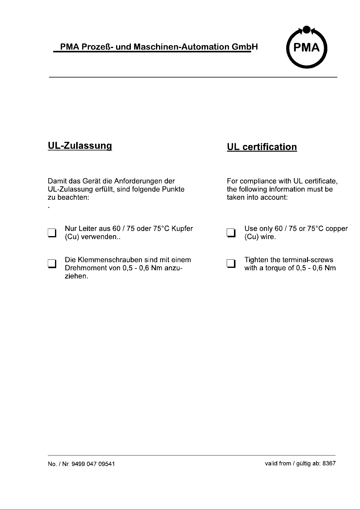
UL-Zulassung .......................................................33
4 9499 040 49111
Page 5

Multi-Temperature-Controller KS 800
1 Safety hints
Following the enclosed safety hints 9499 047 07101 is indispensable!
For hints on the power supply to be used, see section 4.3 Supply voltage
1.1 Electromagnetic compatibility
The unit conforms to European guideline 89/336/EEC and is provided with the CE marking. The
following European generic standards are met: Electromagnetic radiation: EN 50081-1 and elec-
tromagnetic immunity: EN 50082-2
For compliance with EN 50082-2, the analog input leads must be screened.
The unit is suitable for use in industrial areas (there may be radio interference in residential areas).
Electromagnetic radiation can be reduced considerably, if the instrument is installed in a grounded
metal control cabinet.
9499 040 49111 5
Page 6

Multi-Temperature-Controller KS 800
2 General
KS 800 is a microcomputer-based multi-loop temperature controller. Functions "set-point lowering"
and "heating/cooling with four alarms" make it ideally suited for temperature control of plastics 20
processing machinery, moulds, packaging machinery, tempering units and similar thermal processes. Furthermore, with high-power heating elements (e.g. in hot runner moulds), the selectable
functions "start-up circuit" and "output hold" in case of sensor break ensure increased element life
and prevent interruptions during production. The self-tuning feature guarantees very short start-up
times.
2.1 Versions
These operating notes are valid for the three versions, which are only different in the communication interface:
Multiple temperature controller with RS485 / RS422 interface and ISO 1745 protocol.
9407 480 00001 KS 800-RS: Without analog outputs
9407 480 00101 KS 800-RS: With analog outputs, standard current signal 0/4...20mA
9407 480 00201 KS 800-RS: With analog outputs, standard voltage signal 0...10V
9407 480 00301 KS 800-RS: With 10V= constant-voltage
Multiple temperature controller with Profibus DP interface and Profibus DP protocol.
9407 480 30001 KS 800-DP: Without analog outputs
9407 480 30101 KS 800-DP: With analog outputs, standard current signal 0/4...20mA
9407 480 30201 KS 800-DP: With analog outputs, standard voltage signal 0...10V
9407 480 30301 KS 800-DP: With 10V= constant-voltage
Multiple temperature controller with CANbus interface and CANopen protocol.
9407 480 60001 KS 800-CAN: Without analog outputs
9407 480 60101 KS 800-CAN: With analog outputs, standard current signal 0/4...20mA
9407 480 60201 KS 800-CAN: With analog outputs, standard voltage signal 0...10V
9407 480 60301 KS 800-CAN: With 10V= constant-voltage
Multiple temperature controller with CANbus interface and Device-Net protocol.
9407 480 70001 KS 800-DN: Without analog outputs
9407 480 70101 KS 800-DN: With analog outputs, standard current signal 0/4...20mA
9407 480 70201 KS 800-DN: With analog outputs, standard voltage signal 0...10V
9407 480 70301 KS 800-DN: With 10V= constant-voltage
The differences between the KS 800 versions are only in the field bus / serial interface.
6 9499 040 49111
Page 7
Multi-Temperature-Controller KS 800
2.1.1 Possible output configurations
Provided that other criteria are taken into account, the following controller configurations are
possible:
Signaller with one output
Signaller with two outputs
Two-point controller (heating switching)
Three-point controller (heating switching, cooling switching)
Three-point controller (heating continuous, cooling switching)
Three-point controller (heating switching, cooling continuous)
Three-point stepping controller (without position feedback)
Continuous controller
Split-range controller (heating and cooling continuous, 0...100% each; max. 4 controllers)
Three-point controller with watercooling (water vaporization)
Limitter with latch function
When configuring a controller output as a continuous output, the relevant switching output is firmly
assigned to 0% duty cycle.
With unused analog outputs, the output variable is 0V or 0mA.
3 Installation
3.1 Mounting
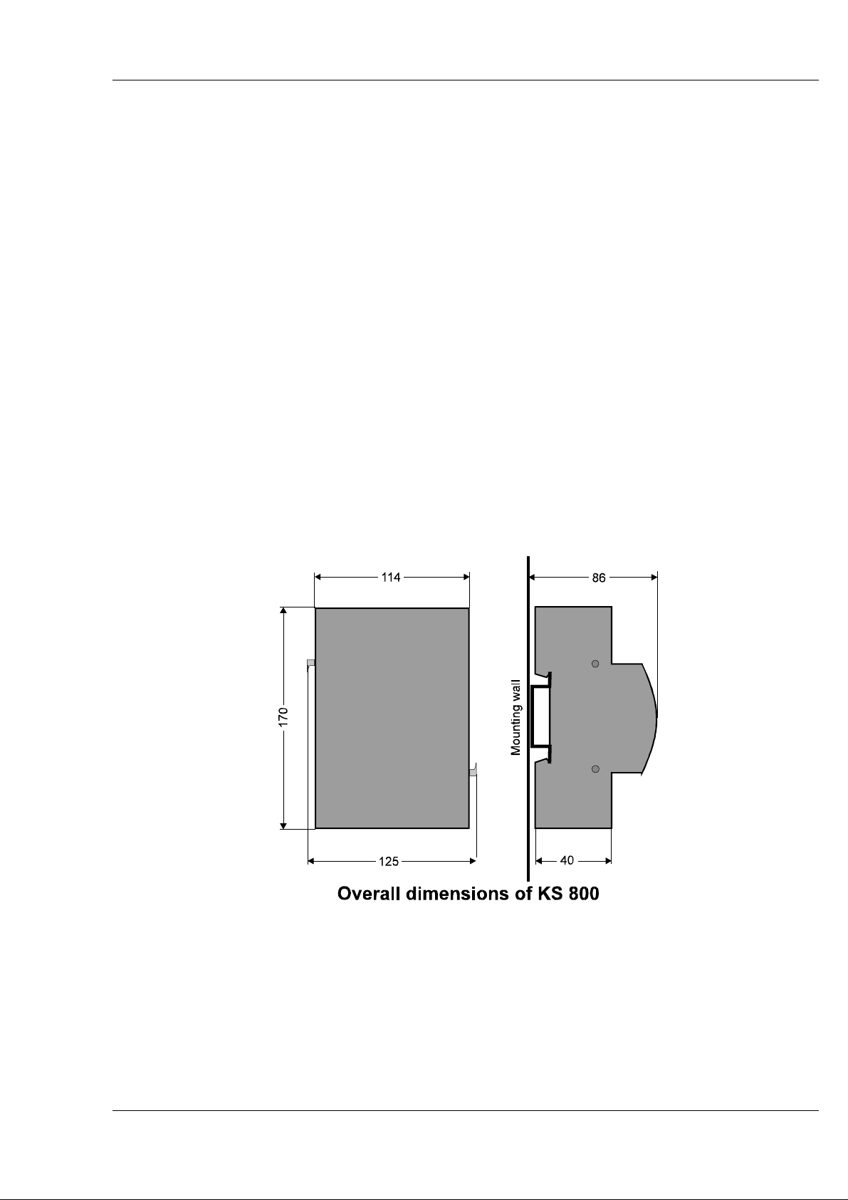
KS 800 is provided for fast clip-on mounting to "top hat" standard rails 35 x 7,5 to EN 50 022,
EN 50 035 and EN 50 045.
KS 800 earthing is via a spring to the "top hat" rail. Therefore, this rail must have a good, conducting connection with the grounded mounting wall (layer of lacquer, non-conducting mounting wall,
Eloxal, ...). If necessary, the "top hat" rail must be earthed using a separate connection.
Single unit: For mounting, pull the two latches on the sides upwards by approx. 5 mm via a click
point and snap on the unit to the mounting rail. Press these latches down to lock the unit in position
on the rail.
9499 040 49111 7
Page 8

Multi-Temperature-Controller KS 800
Several units: For mounting several units side by side, snap on the first unit to the rail and lock
only the side on which no
approx. 2 cm beside the first unit and shift it sideways to connect it to the first unit (locking pins
click into position). Press down the second latch of the first unit only now.
The connectors on the instrumentside (board-toboard connector; type: AMP champ-050-connection)
are used only
units mounted side by side.
for CANBUS through-connection, i.e. one CANbus connection is sufficient for several
other unit shall be mounted. Snap on the second unit like the first one,
Bus connectors: These connectors are not
this case, each unit must be connected to the bus separately via the 9-pin sub-D-connectors.
If the KS 800 units are operated together with other P-Open components in a CANbus system, the
KS 800 units must be connected as last
by side on a rail. Otherwise, the individual component cannot be addressed. (The "addressing line"
is interrupted by KS 800.)
3.2 Dismounting
For dismounting, the leads need not be disconnected.
Before removing, mark the upper parts of the connectors and the corresponding lower parts, because the terminals are protected by design against distortion but not against wrong polarity.
For releasing the upper part of a terminal, press the two red ejectors in a terminal row towards the
circuit board by means of a screwdriver, if necessary.
For releasing the unit from the mounting rail, draw the two side latches (1) forwards by approx.
5mm (latch released) and remove the unit from the mounting rail by tipping it down or up.
For replacing an "inner" one of several units mounted side by side, start releasing the latch (and the
latch of the following unit!) at the end of the row and shift the unit sideways. Repeat this procedure
until reaching the unit which must be replaced. When its locking pins are free on both sides, the unit
can be tipped down or up out of the mounting rail.
used with the KS 800 Profibus and RS485 versions. In
instruments at the left or the right end of the modules side
8 9499 040 49111
Page 9
Multi-Temperature-Controller KS 800
4 Electrical connection
• Measurement and signal leads may carry max. 50 V rms against earth.
• Mains cables must be kept separate from signal and measurement cables.
• For protection of the outputs and avoiding interference, connected final elements must be
fitted with protective circuits according to manufacturer specification.
4.1 Terminals
All terminals leading to the process are designed as (plug-in) screw terminals or spring clamps.
The terminals are not included in the scope of delivery and must be ordered separately.
Type: PHOENIX COMBICON
Two types are available:
Screw terminal 4 x FRONT-MSTB 2,5/18-ST-5,08 1 x FRONTMSTB 2,5/8-ST-5,08
PMA Order-No. 9407 799 00001 9407 799 00011
Spring clamp 4 x FK-MSTBP 1,5/18-ST-5,08 8-pole not suitable
PMA Order-No. ----- ----For units with analog outputs,
2 x 8-pole terminal, order no. 231-308/026-000, resp. 9407 799 00011
is required additionally.
Note: The screwless spring clamps are shown in the KS 800 figures. These clamps have a sepa-
rate test socket. With the screw terminals, the screw heads are used for test measurements.
Connecting capacity
FRONT-MTSB 2,5/...-ST FK-MSTBP 1,5/...-ST
rigid flexible1) rigid flexible1)
One wire [mm²] 0,2 - 2,5 0,25 - 2,5 0,2 - 1,5 0,25 - 1,5
Multiple-wire connection [mm²]2) 0,2 - 1,5 0,25 - 1,0 0,2 - 1,0 0,5 - 0,753)
1
) with end crimps
2
) 2 wires of equal cross section
3
) with TWIN end crimps
Type : WAGO Multi-Connection-System MIDI
Spring-clamp 4 x female connector with CAGE CLAMP order no. 231-318/026-000
PMA Order-No. 9463 000 05341
1 x female connector with CAGE CLAMP order no. 231-308/026-000
PMA Order-No. 9463 000 05321
Connecting capacity
Only one wire: 0,08 - 2,5 mm², single-wire, multiple-wire, fine-wire, end crimp, pin cable shoe
9499 040 49111 9
Page 10
Multi-Temperature-Controller KS 800
For units with analog outputs,
2 x 8-pole terminal, order no. 231-308/026-000, resp. 9463 000 05321 is required additionally.
4.2 Bus-Stecker
For connecting KS 800 to the fieldbus system, the connectors listed in the table must be used:
Profibus Canbus; RS422/485 DeviceNet
z.B. Siemens*)
6ES7 972-0BA10-0XA0
6ES7 972-0BA10-0BB0
Sub-D-connector/socket; prefer commercially available metal/metalized
versions
Special adaptor
PMA order no.
9407 799 00301
6ES7 972-0BA10-0BA0
6GK1 500-0EA00
*
)These connectors are not available from PMA.
Specification of the order number is not binding, as these numbers can always be changed by
Siemens.
Note! For pin allocation see chapters 8.2.1 und 8.2.2
10 9499 040 49111
Page 11
Multi-Temperature-Controller KS 800
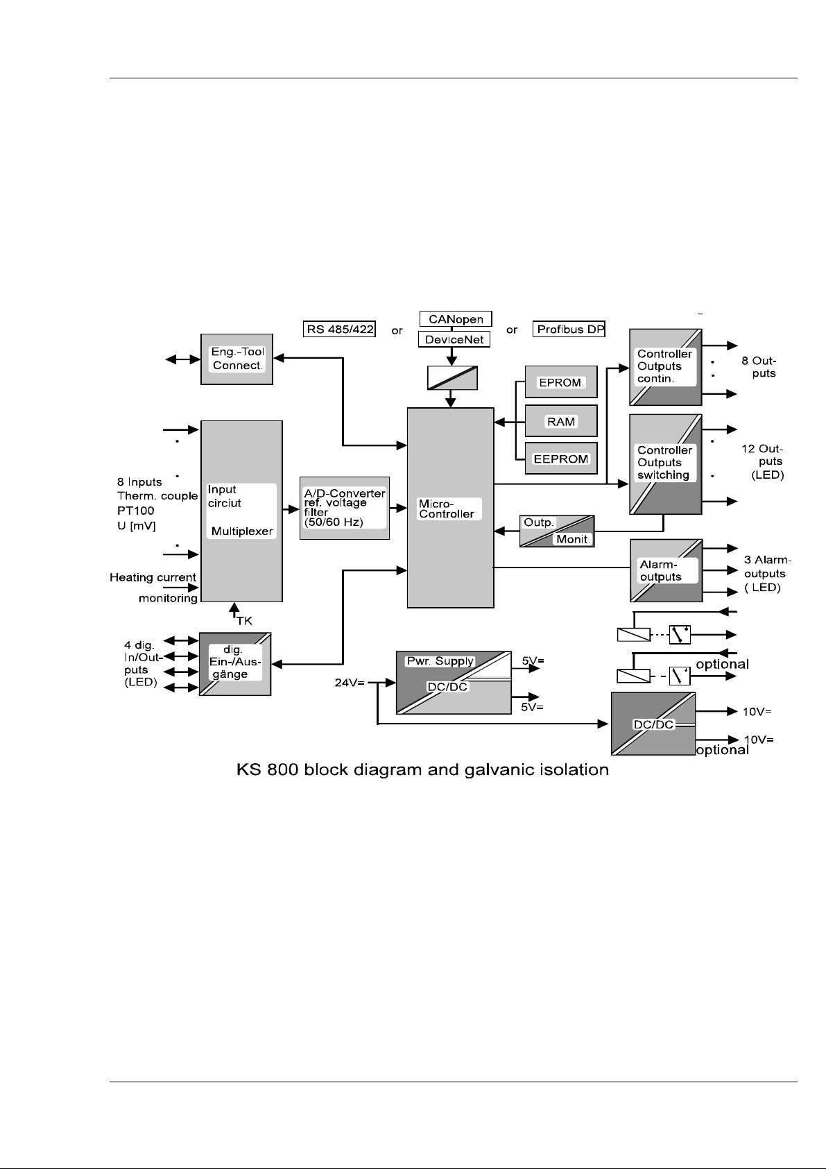
4.3 Galvanic isolations
The galvanic isolations of KS 800 are shown in the following diagram.
Identical block shading means that blocks are galvanically connected.
I.e. all outputs are galvanically connected, but isolated from inputs and microcontroller (controller).
All inputs are also galvanically connected.
An exception are the digital inputs/outputs, which are connected with controller outputs (and supply
voltage) independent of their configuration.
9499 040 49111 11
Page 12
Multi-Temperature-Controller KS 800
4.4 Supply voltage
KS 800 is designed for a supply voltage rating of 24V DC, range 18V to 30V, residual ripple 5%.
The supply voltage must comply with the conditions of protective low voltage (SELV) according to
IEC 364-4-41 [VDE 0100-410].
Power supply load by one
8 controller outputs + 4 alarm outputs each with 0,07A 20,16W
plus controller consumption 5,50W
results in a max. overall load (at 24V) of approx. 25,60W
KS 800:
The supply voltage minus pole is connected via the two external terminals (1 and 18) of
connector J1.
The plus pole is connected via terminals 19 and 36 of connector J2.
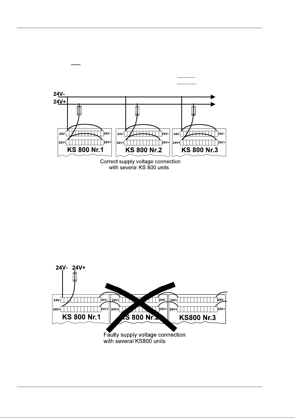
The supply voltage must always be connected from both sides, in order to prevent overload of
the circuit tracks.
We recommend using rail-mounted terminals with built-in fuse.
When mounting several units side by side, supply from one side and subsequent passing on
to the following unit must be avoided!
4.5 Fuses
Each unit must be protected with a separate fuse (in rail-mounted terminal) 2A, medium-fast.
Unless the "PWR" LED is lit with the supply voltage applied (check external fuse and polarity!), the
unit is defective and must be returned to the manufacturer.
12 9499 040 49111
Page 13

Multi-Temperature-Controller KS 800
5 Inputs
(A complete KS 800 connecting diagram is given in section 7.)
Examples for connection are given in section 5.7.
The following rules are applicable to all analog inputs:
Unused analog inputs must be short-circuited!
Thermocouple and DC voltage:
Connect + and - terminal of each input.
Resistance thermometer:
Unused inputs for resistance thermometers must be configured as mV or ther
mocouple input. In this case, the + and - terminal of an input must also be
connected.
5.1 Analog inputs IN1...IN8
These analog inputs are the process value inputs of control loops1-8.These inputs can be configured for thermocouple, resistance thermometer or voltage. Within a controller, "mixed operation" of
inputs is possible.
5.1.1 Thermocouple inputs (IN1+/IN1- ... IN8+/IN8-)
The following thermocouple types according to DIN/EN 60584 can be connected:
Thermocouple
type
Old description Ident. colour
neg. wire
Range
L Fe/CuNi blue 0... 900°C
J Fe/CuNi black 0... 900°C
K Ni-Cr/Ni green 0...1350°C
N Nicrosil/Nisil pink 0...1300°C
S Pt-10/Rh/Pt orange 0...1760°C
R Pt-13/Rh/Pt white 0...1760°C
T Cu/Cu-Ni brown 0... 400°C
W*) W5Re/W26Re not defined 0...2300°C
E Ni-Cr/Cu-Ni violett 0...1000°C
*
)not according to DIN/EN
The upper KS 800 measuring limit is the upper limit for operation of the relevant thermocouple type.
The thermocouples are monitored for polarity error and break and the action (upscale/downscale) is
configurable.
All thermocouples must be connected with correct polarity at terminals INx+ and INx-.
With thermocouples to DIN 43710, the plus arm is red and the colour of the minus arm corresponds
to the identifying colour of the thermocouple type.
According to DIN/IEC 584, the colour of the plus arm corresponds to the identifying colour of the
thermocouple type and the minus arm is white.
Terminals IPTx remain free.
9499 040 49111 13
Page 14

Multi-Temperature-Controller KS 800
The controller inputs are not galvanically isolated. Therefore, measurement errors may occur with
thermocouple measurements above approx. 700°C and unsuitable thermocouples. This effect is due
to a decrease of the insulation value between protective tube and thermocouple to values of
a few kOhm from these temperatures dependent of construction type and insulation material.
Additionally, potential differences between the individual thermocouples due to hot gas ionization
may cause measurement errors or troubles due to compensating currents.
For the same reason, there may be problems when using grounded and isolated thermocouples in
mixed applications. The potential differences between thermocouples must not exceed 7Vss.
We urgently recommend avoiding mixed operation.
If using grounded and isolated thermocouples in an installation should be indispensable for
other reasons, the negative arm of the isolated thermocouple must be grounded at KS 800.
Already grounded thermocouples must not be grounded for a second time!
When replacing isolated thermocouples by non-isolated ones, removal of the negative arm
grounding at KS 800 is indispensable.
5.1.2 Cold-junction temperature compensation
There are four possibilities of temperature compensation:
1. The temperature compensation is ineffective (for PT 100 or mV inputs)
2. Internal temperature compensation. Compensating lead must be used up to KS 800.
3. External temperature compensation. Compensating lead must be used only up to the
cold-junction reference, leads between reference and KS 800 can be of copper.
4. Remote measurement of a cold-junction reference. Input IN8 can be configured so that it
functions as input of the temperature sensor of a remote cold-junction reference.
The thermocouples of each individual measuring point are connected to a common coldjunction reference by means of compensating lead. The leads between cold-junction reference and KS 800 can be of copper. The 8th input is used for measuring the temperature of
this cold-junction reference and correcting the input voltage accordingly. For maintaining the
specified accuracy, the sensor should be a resistance thermometer. When using this temperature compensation method in an installation containing several KS 800 controllers, this
method must be used with each individual unit.
5.2 DC voltage (<100mV) IN1+/IN1- ... In8+/IN8DC voltages up to 100 mV instead of thermocouples can also be connected. Scaling of these valu-
es is possible via software adjustments.
The input resistance is approx. 100 kΩ.
14 9499 040 49111
Page 15

Multi-Temperature-Controller KS 800
5.3 Resistance thermometer (IN1+/IN1-/IPT1 ... IN8+/IN8-/IPT8)
Pt 100, 2 or 3-wire connection
Resistance thermometer type PT 100 to DIN/IEC 751 can be connected in 2 or 3-wire circuit. The
max. measuring range is -100,0 ... 850,0°C, temperature-linear.
Connection in 3-wire circuit is possible without lead resistance adjustment, provided that the crosssection of the individual wires is identical.
With 2-wire connection, a compensating resistor corresponding to the lead resistance must be fitted.
Using 2-wire connection is not recommendable.
The sensor is monitored for short circuit or break. The action (upscale/downscale) is configurable.
Resistance
wInstead of Pt10, a linearly variable resistor can be connected as a signal source in 3-wire circuit (
for connection, see section 7.1), 2-wire connection is not possible.
The max. resistance can be 400 Ω. The measuring range starts at 0Ω to the final resistance value
(max. 400Ω) The output action is reversible by connecting the wiper either to IN+ or IN- .
Monitoring is only for lead break.
5.4 Screening
For compliance with the regulations on electromagnetic compatibility to EN 50082-2, the connecting
cables must be screened. The 2 screening possibilities are:
1. Each input is provided with a grounded screen connecting terminal to which the cable
screening must be connected. These interconnected screenings must be connected to the
ground potential (protective earth) via terminal 108 by means of the shortest possible cable
(approx. 20 cm).
2. Use a commercially available screen connecting system.
5.5 Heating current measurement and heating current alarm
KS 800 has an input for connection of an external current transformer. All heating loads connected
to a controller module are taken through a current transformer. Further processing and evaluation of
the transformer signal are in the multi-controller module.
Measurement principle:
current monitoring for a controller is possible after each 4th cycle, i.e. at intervals of 2,25 s. Via
software, this interval can be increased by a factor between 0 and 99 in common for all controllers,
whereby 0 means no monitoring.
E.g. factor 10: heating current monitoring for controller 1 is done after 22,5 s. After another 22,5 s,
the heating current of controller 2 is monitored, etc., i.e. controller 1 is monitored again after 9 x
22,5 s = 202,5 s ≈ 3,5 min. Monitoring switch-off for individual controllers does not affect the cycle
time.
As all controllers except the one to be monitored are switched off during monitoring (which is swit-
ched on independently of its control status), the control accuracy can be affected negatively. Therefore, heating current monitoring should be done only as frequently as necessary rather than as
frequently as possible.
a KS 800 "control cycle" takes approx. 600 ms for all 8 controllers. Heating
9499 040 49111 15
Page 16

Multi-Temperature-Controller KS 800
The current transformer input is not a measurement input in the sense of a calibrated measuring
instrument. The software for display calculation is designed for a single-phase 1000:1 current transformer (30A = 30mA). When applying other values to this input, there will be an error (3-phase
transformers, wave-form factor due to rectification and internal resistance outside KS 800...). Nevertheless, applying other variables to this input, e.g. 3-phase transformer with subsequent rectification
and totalizing is possible. In this case, scaling is not correct any more.
Therefore, the KS 800 current input must be matched to the relevant conditions:
Allow the current to be monitored of one heating loop to flow through the transformer. The relevant
controller measurement value is in a fixed ratio to the current, as long as the linearity limits are not
exceeded. E.g. the KS 800 display with 27A heating current is 19(A) (by additional external rectification with a higher internal resistance). For monitoring a 10% current decrease, a limit of 17,1 (A)
must be adjusted.
However, the absolute measurement limits of transformer and KS 800 must not be exceeded:
1. The maximum current through the transformer(s). (When heating up the machine, all
heatings are switched on and the total of all heating currents flows through the
transformer(s). This current must be below the max. value permissible for this transformer,
otherwise, the transformer can be destroyed. For our transformers 9404 407 500x1, the
current limit is 100 A.
2. The maximum KS 800 input current must not exceed 100 mA (thermal limits).
3. Measurement is linear within 0 and approx. 35 mA.
When detecting an exceeded limit, this information is available at one of the alarm outputs or can
be read via the field bus.
Monitoring is done for exceeded min. and max. heating current limit.
Exceeded min. heating current limit: with the controller output switched off, an (adjustable)
heating current min. value is monitored, i.e. interruptions of the heating loop are detected.
Exceeded max. heating current limit: with the output switched off, monitoring is done for an
exceeded heating current limit of 3% of the heating current span (HC 100), which indicates leakage
currents.
The dyn. input resistance is approx. 170 Ω
Heating current monitoring is omitted, if a control loop is switched off.
16 9499 040 49111
Page 17

5.6 Input circuit examples
Multi-Temperature-Controller KS 800
5.7 Digital inputs
KS 800 contains 4 digital inputs, which can also be configured individually as inputs, unless required as controller outputs (cooling output with three-point controllers or closed output with three-point
stepping controllers).
The inputs are "high-active" and designed as current sink according to IEC 1131 type 1. The current
requirement is approx. 5 mA.
Logic "0" = -3...5 V
Logic "1" = 15...30 V
With configuration as input, the following allocation is applicable:
IN/OUT13: control parameter set 1/2 switch-over
This input is used to activate the 2nd control parameter set in common with all controllers which are configured accordingly.
IN/OUT14: controller switch-off
This input is used for common switch-over of all controllers configured accordingly to
manual mode and for setting the outputs to "0". All other configured functions
continue operating normally.
See also hint on page 21.
IN/OUT15: Input for leakage current monitoring
The logic signal of an external leakage current monitor can be connected to this
input.
IN/OUT16: W/W2 switch-over
This input is used for activating the 2nd setpoint (W2) with all controllers configured
accordingly.
Unused digital inputs need not be connected.
9499 040 49111 17
Page 18

Multi-Temperature-Controller KS 800
5.8 Input/output forcing
Unless connections IN/OUT13...IN/OUT16 or OUT17...OUT19 are used for their actual tasks, they
can be used as "free digital inputs/outputs" of a supervisory system. In this case, they cannot be
influenced by KS 800, but only as a system component via the system bus.
Inputs/outputs IN/OUT13...IN/OUT16 can be configured as digital inputs or outputs.
Alarm outputs OUT17...OUT19 can be used as digital outputs, whereby the electrical specifi-
cations of these inputs and outputs remain unchanged.
18 9499 040 49111
Page 19

Multi-Temperature-Controller KS 800
6 Outputs
(For the complete connecting diagram, see section 7.2, 7.3)
6.1 Controller outputs:
Dependent of controller configuration, various output functions are possible:
2-pnt. controller
signaller
1 output
1
)
3-pnt. controller
signaller
2 outputs
2
)
3-pnt. stepping
controller
OUT 1 heating (contr. 1) heating (contr. 1) open (contr. 1)
OUT 2 heating (contr. 2) heating (contr. 2) open (contr. 2)
OUT 3 heating (contr. 3) heating (contr. 3) open (contr. 3)
OUT 4 heating (contr. 4) heating (contr. 4) open (contr. 4)
OUT 5 heating (contr. 5) heating (contr. 5) open (contr. 5)
OUT 6 heating (contr. 6) heating (contr. 6) open (contr. 6)
OUT 7 heating (contr. 7) heating (contr. 7) open (contr. 7)
OUT 8 heating (contr. 8) heating (contr. 8) open (contr. 8)
OUT 9 switched off cooling (contr. 1) closed (contr. 1)
OUT 10 switched off cooling (contr. 2) closed (contr. 2)
OUT 11 switched off cooling (contr. 3) closed (contr. 3)
OUT 12 switched off cooling (contr. 4) closed (contr. 4)
IN/OUT 13 input or unused cooling (contr. 5) closed (contr. 5)
IN/OUT 14 input or unused cooling (contr. 6) closed (contr. 6)
IN/OUT 15 input or unused cooling (contr. 7) closed (contr. 7)
IN/OUT 16 input or unused cooling (contr. 8) closed (contr. 8)
1
) Outputs OUT1 to OUT8 are the "signal outputs".
2
) Outputs OUT1 to OUT8 are the "signal outputs 1" and the outputs OUT9 to OUT16 are the
"signal outputs 2".
KS 800 has max. 19 outputs with identical specification:
Transistor outputs, + switching (for loads with common minus connection).
Rated output current:< 70 mA, short-circuit proof
Voltage drop with full load: typ. 0,3 V, max. 1,0 V
OUT1...OUT12 12 fixed logic outputs (controller outputs). The controllers and control-
ler output allocation are fixed. Reconfiguration is not possible.
IN/OUT13...IN/OUT16 4 variable inputs/outputs. They can be configured as controller outputs
(logic outputs) or digital inputs.
9499 040 49111 19
Page 20

Multi-Temperature-Controller KS 800
OUT17...OUT19 3 outputs for alarms. The alarm allocation to the three outputs is confi-
gurable.
Unused outputs cannot be switched off individually. These outputs go to the status which is defined
in the KS 800 configuration. The inputs of these unused controllers must be short-circuited (see
also section 5).
Because of the variety of KS 800 configurations, note that:
The KS 800 options can be limited by the controller configuration.
With KS 800 configuration as two-point controller, all unused inputs/outputs are available for the
option.
With KS 800 configured as three-point controller (heating/cooling) or as three-point stepping controller, 16 output are required with eight control loops, i.e. several options are not possible.
6.2 Controller outputs, continuous
The continuous controller terminals are accessible from the bottom through a cut-out in the
aluminium profile. Two 8-pin connectors must be used for connection.
The type of continuous outputs (voltage or current) is dependent of the KS 800 type (see section
2.1 Versions) and cannot be changed.
The current output, dead-zero (0mA) or live-zero (4mA), is adjustable via software.
Current output
Voltage output 0...10V
0/4...20mA
Range
Accurcy
Resolution
Load
Settling time
Overload pro-
0...20mA / 4...20mA 0...10V
typ. ± 0,2% ±1 digit typ. ± 2 digits
9 bits 9 bits
max. 470 Ω min. 6 kΩ
max. 625 ms max. 625 ms
----1) short circuit proof
tection up to
1
) With low load resistances, the most important part of the power is converted (into heat) in KS800
itself, which implies a risk of instrument overheating, especially with high ambient temperatures.
With all eight controllers configured as current outputs, the load resistances should not be lower
than 250 Ω.
6.2.1 Analog output allocation
There are 2 modes of analog output allocation to the hardware outputs:
1. Up to instrument number 8396 (Dec. 2001) operating version 4:
Continuous outputs cannot be allocated firmly to the controllers and thus to the terminals. The order
of allocation is as with controller configuration with analog outputs.
20 9499 040 49111
Page 21

Multi-Temperature-Controller KS 800
Starting with controller 1, the 1st controller, which has a continuous output, is allocated to analog
output 1 (AO1).
E.g. controller 1 and 2 are two-point controllers (heating, switching), controller 3 is configured as a
three-point controller (heating switching, cooling continuous): the first free analog output (AO1) is
allocated to the cooling output of controller 3. (The output of the 3rd controller is connected with the
1st analog output (AO1).) Analog output 2 (AO2) is used by the following controller output which is
configured as an analog output. Analog outputs which are added or removed subsequently shift the
controller ⇔ analog output allocation.
When planning or changing the installation, note that controller outputs and
analog outputs must not have the same numbering.
2. From Instrument number 8397 (Jan. 2002), operating version 5
The analog output allocationto the hardware output is fixed: controller 1 -> analog output 1,
controller 2 -> analog output 2, etc. Analog outputs which are not required for individual controllers
can be used for analog output of other variables (Xeff, Weff, Ypid, Y1heating, Y2cooling of this
channel, or for forcing.
6.3 Alarm outputs
The three alarm outputs of KS 800 are accessible at connector J3.
The alarms
HC alarm: alarm is output with the heating current below
value (to ensure the heating power; high impedance of heating elements develops slowly).
Leakage current alarm: Alarm generated in case of differential current due to insulation
error. Monitoring is done by an external unit for differential current monitoring with relay
output. This relay provides error signalling to digital input IN/OUT15 configured for this purpose. The insulation error can be signalled via the fieldbus or via an alarm output
(OUT17...19).
the adjusted controller-specific limit
Caution!!! Never use this leakage current alarm message for monitoring of
faulty currents which are inteded for safety against contact with high
voltages.
Output monitoring alarm: alarm is output if one of outputs OUT1...OUT8 does not go to
the status determined instantaneous by the control algorithm.
can be allocated to each of alarm outputs OUT17...OUT19. The outputs are "open-collector outputs"
and can be configured for normally closed or normally open operation.
For detailed information on the configuration, see manual 9499 040 49211.
With the unit configured accordingly, the alarm LEDs (AL1...AL3) are lit when an alarm is pending,
independent of whether the output is or is not connected. The software evaluation of alarms is also
independent of the hardware evaluation.
9499 040 49111 21
Page 22

Multi-Temperature-Controller KS 800
Note: Unless these alarm outputs are used as alarm outputs, they can also be used as digital
outputs of a control system (see also section 5.8).
6.4 Constant voltage and auxiliary relays
KS 800 version 9407 480 xx3xx is provided with a constant voltage source, which is galvanically
isolated from all other KS 800 inputs and outputs.
This constant voltage source can be used for energizing a strain-gauge bridge (pressure sensor).
Galvanic isolation permits direct connection of the bridge diagonal (bridge output) via a KS800 input
configured as a mV-input.
U = 10V ± 0,2%; Imax = 60mA
The constant voltage source is protected against short circuit without being permanently short circuit
proof.
Sensors used for pressure measurement are normally provided with a built-in resistor, which chan-
ges the bridge output signal by 80% if connected in parallel to a bridge arm.
Therefore, function checking is possible after de-pressurizing.
For connecting this resistor in parallel, this KS 800 version is fitted with an additional relay with
change-over contact, which can be controlled by applying an external voltage (24V= from a digital
system output card; current sink type1 to IEC 1131) or via the system bus.
The relay is designed for switching "dry circuits". For using the relay for this purpose, the switching
current must not exceed 2mA, to prevent an increase of the contact resistance (burning off or
oxydation due to spark formation), which leads to bridge output measurement errors.
22 9499 040 49111
Page 23
Multi-Temperature-Controller KS 800
7 Circuit diagrams
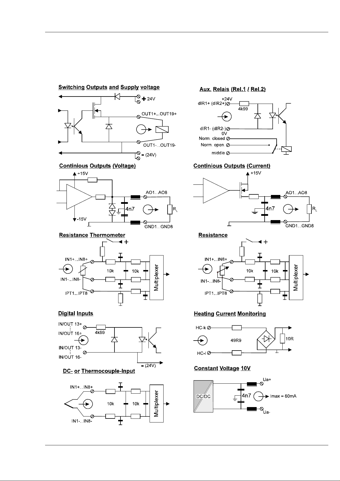
7.1 Input/output circuit diagram
For better understanding with complex connecting problems, the circuit diagrams of inputs and
outputs are shown below.
9499 040 49111 23
Page 24
Multi-Temperature-Controller KS 800
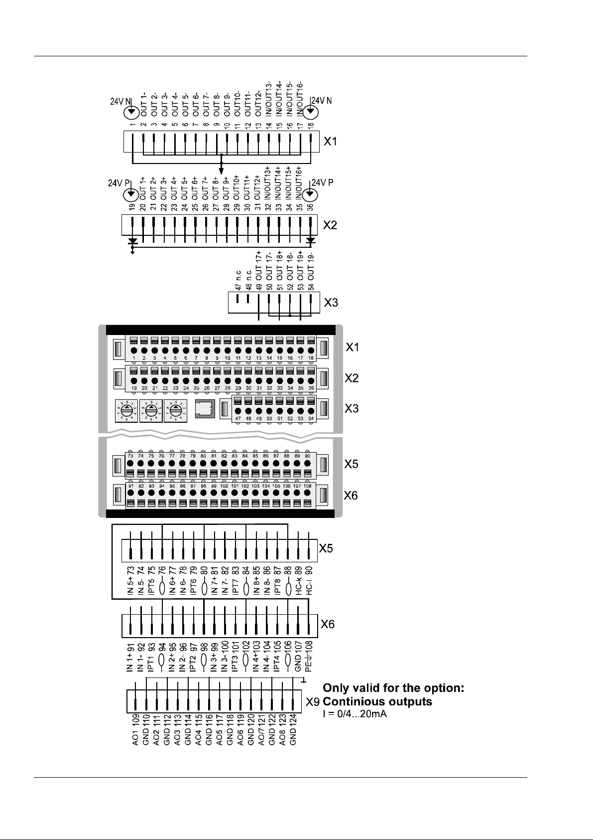
7.2 KS 800 overall connecting diagram with/without continious outputs
24 9499 040 49111
Page 25
Multi-Temperature-Controller KS 800
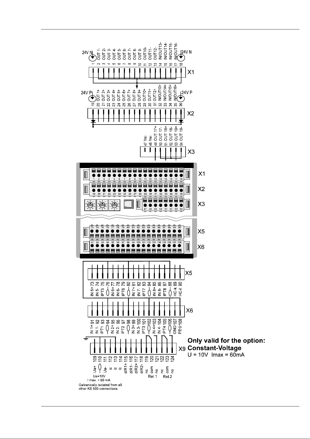
7.3 KS 800 overall connecting diagram with constant voltage 10V
9499 040 49111 25
Page 26

Multi-Temperature-Controller KS 800
8 Digital interfaces
Communication with controller KS 800 is possible only via the digital interfaces. Reading process
values, changing set-points or control parameters is always done via these interfaces.
There are two types of interfaces:
8.1 Engineering tool interface
The PC interface is provided on all controller versions. This interface is a special interface using the
ISO 1745 protocol. Access to all controller values is possible using the relevant software, the engineering tool. E.g. for simple applications or test circuits, an individual unit can be configured and the
control loops can be operated normally via this interface.
Connection is to the 4/4 FCC68 data connector (Western telephone connector) via a special
PC adaptor, order no. 9407 998 00001.
8.2 BUS interfaces
This interface is used for connecting the KS 800 to a PLC, a PC or a visualization unit. Dependent
of version, the interface is designed for CANbus, CANbus with DeviceNet-protocoll, Profibus or as
RS 422/485 (see section 2.1). The 9-pole sub-D connector and socket are equivalent. They are
used for "through-connecting" the bus with several connected controllers.
See also page 8: Bus connectors
8.2.1 BUS-Connector
Con-
tact
1 n.c. n.c. n.c.
2 n.c CAN-L GND
3 n.c.RxD/TxD-P CAN-GND TXD-B
4 DGNC n.c. RXD-B
5 n.c. n.c. RGND
6 Vp(+5V) CNA-GND n.c.
Profibus CANbus RS422/485 DeviceNet
See chapt. 8.2.2
"DeviceNet-Adaptor"
7 n.c. CAN-H GND
8 RxD/TxD-N n.c. TXD-A
9 n.c n.c. RXD-A
26 9499 040 49111
Page 27

Multi-Temperature-Controller KS 800
8.2.2 DeviceNet adaptor
If KS 800 is operated with DeviceNet, an adapter is required for this bus system. This adaptor is
available under order number 9407-799-00301.
Pin allocation DeviceNet adaptor
Mounting the adaptor on the KS 800 sub-D-connectors is done as shown in the following drawing:
DeviceNet adaptor mounting
9499 040 49111 27
Page 28
Multi-Temperature-Controller KS 800
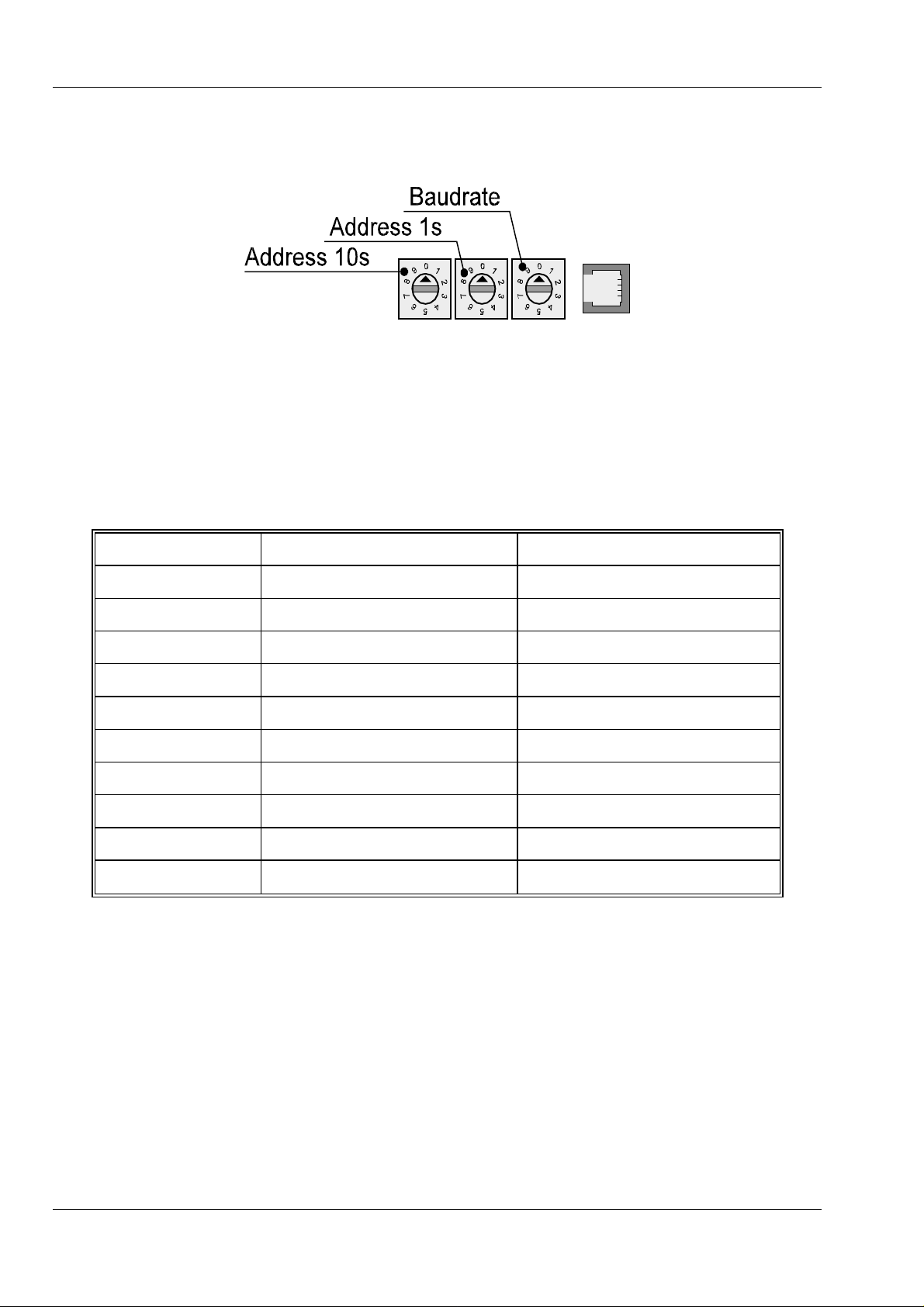
8.2.3 COM2 interface
Address and Baudrate for the COM2 interface can be adjusted via hardware or software for each
KS 800.
Via hardware, the address is adjustable within ”01” and ”99”. In position ”00”, the address stored in
EEPROM which can be changed via software will be used when switching on. Priority is given to
the address adjusted via switch position. This address and baudrate cannot be readout or changed
via software.
The same applies to the Baudrate: in Position ”0”, the EEPROM Baudrate is effective at first. This
address can be changed via software. The digits on the switch correspond to the values used for
determination of the Baudrate during configuration in C902.
Switch position RS485 CANbus
0 from EEPROM or via software from EEPROM or via software
1 2400 Bd 20 kBd
2 4800 Bd 125 kBd*)
3 9600 Bd 500 kBd*)
4 19200 Bd 1 Mbd
5 invalid setting 10 kBd
6 invalid setting 50 kBd
7 invalid setting 250 kBd*)
8 invalid setting 800 kBd
9 invalid setting invalid setting
As the baudrate is adjusted automatically with the PROFIBUS DP-version, manual adjustment is
omitted.
*
) Only these Baudrates are available for DeviceNet. With faulty switch position 125 kBd is set
automatically.
28 9499 040 49111
Page 29

Multi-Temperature-Controller KS 800
8.3 Terminating resistors
Hints related to baudrates, bus lengths, properties of electrical cables and mutual effects are given
in the relevant interface descriptions.
All KS 800 versions are delivered without terminating resistors at the bus connectors which must be
plugged into the free bus connector of the last unit.
The resistors required for each bus must be added externally to the last unit at both ends of the bus
cable. Eihter in the last connector (socket) or in a separate terminating connector (socket), which
must be plugged into the free bus connector of the last unit.
The standards or standard drafts of the relevant bus system are applicable
RS485/422: Unlike the other bus cables, these cables are not standardized. Therefore, no general
data on terminating resistors can be provided. The wave resistance is dependent of cable type and
length. Follow the guidelines provided by the cable manufacturers and connect the terminating
resistors across lines A and B of the relevant conductor pairs TXD and RXD (values approx.
100...200 Ω).
CAN bus (Canopen and DeviceNet): 9-pole sub-D socket with terminating resistor. Only ter-
minating resistor, not suitable for connecting a cable. PMA order no. 9407 800 90021
DeviceNet: The 120 Ω; 5%; 0,25W terminating resistor must be connected to the unused terminals
of the DeviceNet connector across connections blue (BU) and white (WH) (see also drawing, section 8.2.2).
PROFIBUS: e.g. Siemens, bus connector, types 6ES7972-OBB10-OXAO or
6ES7972-OBB20-OXAO, or 6GK1 500-OEAOO. This connector is not available from PMA.
9 Indicator LEDs
9.1 Outputs
Below the outputs, 16 indicator LEDs indicate the output status, provided that a definition is given
for all outputs.
If inputs 13 ... 16 are defined as inputs, the indicator LEDs are lit with a high signal applied to the
inputs.
9.2 PWR, COM and alarm indicator LED
Above the input terminals, five other LEDs with the following signification are fitted:
PWR This LED is lit with the supply voltage applied.
COM With CAN_BUS (CANopen and DeviceNet) and RS422/485, this LED
indicates data transmission between KS800 and control system (PC or
visualization) by blinking.
With PROFIBUS, this Led indicates the bus statuses.
LED off: error signalling for "no bus access" (so far not addressed by master)
9499 040 49111 29
Page 30

Multi-Temperature-Controller KS 800
LED on: O.K., cyclic data exchange busy
LED blinks: (2 Hz) data communication interrupted
LED blinks: (4 Hz) PROFIBUS parameter or configuration error
AL1...AL3 With KS 800 configured for alarm functions, these LEDs are lit in case of the
relevant alarm.
30 9499 040 49111
Page 31

Multi-Temperature-Controller KS 800
10 Maintenance and measures in case of trouble
The KS 800 multiple controller needs no particular maintenance. There are no parts in the unit
which need preventive maintenance or care.
10.1 Cleaning
If necessary, the aluminium and plastics components must be cleaned carefully with spirit. Do not
use solvants or scouring agents.
10.2 Trouble shooting
To start with, all possibilities of error in other equipment and connections (input leads, electrical
connections, equipment in the output circuit) should be examined. If the error cannot be located with
the hints given in this section, we recommend returning the controller to the manufacturer:
PMA Prozeß- und Maschinen- Automation GmbH
Service
Miramstraße 87
D 34123 Kassel
If the trouble was found to be due to failure of an external fuse, the trouble cause must be located
and removed. The spare fuse must be of the same type and current rating as the original one.
If the PWR LED does not light up despite correctly functioning fuse and correct polarity of the supply voltage, controller KS 800 is defective and must be returned to the manufacturer for repair.
10.3 Shut-down
Before disconnecting the unit, disconnect the installation
completely from the mains and check that other equipment
connected in the overall installation is not affected.
WARNING! WARNING!
When safe controller operation seems not possible any more, the unit must
be shut down and protected against accidental switch-on.
For removal of the unit, see section 3.2
10.4 Customer Support Hotline
For further questions beyond the scope of the KS 800 operating manual, please, contact one of the
following telephone numbers from Monday to Friday, between 8 a.m. and 16 p.m.
Tel. Custumer Support: 49 561 505 3091
Tel. Repair: 49 561 505 1257
Tel. Sales Dept.: 49 561 505 1307
e-mail: mailbox@pma-online.de
9499 040 49111 31
Page 32

Page 33
Page 34

Page 35

Page 36

Subjekt to alteration without notice.
Printed in Germany 9499 040 49111 (022004)
© PMA Prozeß- und Maschinen-Automation GmbH
P.O.B. 31 02 29, D - 34058 Kassel Germany
 Loading...