

Page 1
DataVU 5 - Operating Manual
59480
Page 2
Page 3

Contents
1 Introduction 7
1.1 Preface .......................................................................................................... 7
1.2 Arrangement of the documentation ........................................................... 8
1.2.1 Structure of this operating manual ................................................................. 8
1.3 Typographical conventions ......................................................................... 9
1.3.1 Warning signs ................................................................................................. 9
1.3.2 Note signs ...................................................................................................... 9
1.3.3 Representation modes ................................................................................. 10
2 Device description 11
2.1 Displays and controls ................................................................................ 11
2.2 Operating principle and graphic elements .............................................. 12
2.3 Analog inputs .............................................................................................. 14
2.4 Digital signals (event traces) ..................................................................... 15
2.5 Counters / integrators / operating time counter ..................................... 16
2.5.1 Reporting period of the counts .................................................................... 18
2.5.2 Resetting the counters / integrators / operating time counters ................... 18
2.5.3 Response to instrument reconfiguration ...................................................... 19
2.5.4 Response at end of summer time ................................................................ 20
2.6 Math/logic module ..................................................................................... 20
2.7 Operating modes ........................................................................................ 23
2.8 Storing data ................................................................................................ 24
2.9 Read-out of data ........................................................................................ 27
2.10 Evaluating data ........................................................................................... 27
2.11 Webserver ................................................................................................... 28
3 Operation and visualization 31
3.1 Basic menu ................................................................................................. 32
Page 4

Contents
3.2 Visualization ................................................................................................ 33
3.2.1 Diagram representation with digital display (small measurements) ............. 34
3.2.2 Diagram representation with scaling ............................................................ 35
3.2.3 Diagram representation with bar graph ........................................................ 35
3.2.4 Large digital display (large measurements) .................................................. 36
3.2.5 Curve representation (header switched off) ................................................. 37
3.2.6 Evaluation of the stored measurement data ................................................ 38
3.2.7 Counters / integrators / operating time ........................................................ 41
3.3 Parameterization ........................................................................................ 43
3.4 Configuration .............................................................................................. 46
3.5 Event list ...................................................................................................... 47
3.6 CompactFlash card .................................................................................... 50
3.7 Device info .................................................................................................. 53
3.8 Text entry ..................................................................................................... 55
3.9 Entering values ........................................................................................... 56
3.10 Code number (password query) ............................................................... 57
4 Configuration parameters 59
4.1 Operating example ..................................................................................... 59
4.2 Table of configuration parameters ........................................................... 60
4.2.1 Parameterization .......................................................................................... 60
4.2.2 Configuration - Instrument (device) data ...................................................... 62
4.2.3 Configuration - Analog inputs ...................................................................... 64
4.2.4 Configuration - Math channels ..................................................................... 66
4.2.5 Configuration - Counter/integrator (extra code) ........................................... 66
4.2.6 Configuration - Recording ............................................................................ 70
4.2.7 Configuration - Outputs (extra code) ........................................................... 73
4.2.8 Configuration - Control functions ................................................................. 74
4.2.9 Configuration - Texts .................................................................................... 74
4.2.10Configuration - Interfaces ............................................................................ 75
4.2.11Configuration - Undocumented parameters ............................................... 76
4.2.12Configuration - Fine calibration ................................................................... 76
5 Setup program 77
5.1 Hardware and software requirements ...................................................... 77
5.2 Installation .................................................................................................. 78
Page 5

Contents
5.3 User interface ............................................................................................. 79
5.4 Configuration .............................................................................................. 81
5.5 Teleservice .................................................................................................. 84
5.6 Data transfer from and to the instrument ................................................ 86
5.6.1 Transfer via CompactFlash memory card .................................................... 86
5.6.2 Transfer via interface .................................................................................... 89
5.7 Connection between the PC and the recorder ........................................ 91
5.7.1 Assistant for device settings ........................................................................ 91
5.7.2 Device list ..................................................................................................... 95
5.8 Menu functions ........................................................................................... 96
5.8.1 File ................................................................................................................ 96
5.8.2 Edit ............................................................................................................... 97
5.8.3 Data transfer ................................................................................................. 98
5.8.4 Extras ........................................................................................................... 98
5.8.5 Window ...................................................................................................... 103
5.8.6 Info ............................................................................................................. 104
5.9 Math/logic ................................................................................................. 105
5.10 Character set ............................................................................................ 109
6 Rights 111
6.1 Rights with regard to the setup program ............................................... 111
7 PC programs 113
7.1 PC evaluation software (PCA3000) ......................................................... 113
7.2 PCA communication software (PCC) ..................................................... 114
8 Identifying the instrument version 115
8.1 Type designation ...................................................................................... 115
8.2 Standard accessories .............................................................................. 116
8.3 Optional accessories ............................................................................... 116
9 Installation 117
9.1 Installation site and climatic conditions ................................................ 117
9.2 Fitting ......................................................................................................... 117
Page 6

Contents
10 Electrical connection 121
10.1 Installation notes ...................................................................................... 121
10.2 Technical data ........................................................................................... 121
10.3 Connection diagram ................................................................................ 122
11 Index 125
Page 7

1.1 Preface
E
B
1 Introduction
Please read these operating instructions before commissioning the
instrument. Keep the operating instructions in a place that is accessible to all
users at all times.
Please assist us to improve these operating instructions, where necessary.
Your comments will be appreciated.
All necessary settings are described in this manual. If any
difficulties should arise during commissioning, you are asked not
to carry out any manipulations that could endanger your rights
under the instrument warranty!
Please contact the nearest subsidiary or the head office in such a
case.
When returning modules, assemblies or components, the
regulations of EN 61340-5-1 and EN 61340-5-2 “Protection of
electronic devices from electrostatic phenomena” must be
observed. Use only the appropriate ESD packaging for transport.
Please note that we cannot accept any liability for damage caused
by ESD.
ESD=electrostatic discharge
7
Page 8

1 Introduction
1.2 Arrangement of the documentation
The documentation for this instrument consists of the following parts:
Operating
Manual
59480
Interface
Description
59482
This operating manual comes with the delivery. It is addressed to the
equipment manufacturer and the user with appropriate technical expertise.
In addition to installation and electrical connection, it contains information on
commissioning, operation and parameter setting on the instrument, as well as
on the optional PC setup program and the optional evaluation program (PCA).
It provides information on the serial interface (RS232 and RS485), which can
be supplied as an extra code. The interface description can be used to
develop specific programs which can, for instance, read out current
measurement data.
1.2.1 Structure of this operating manual
This manual is arranged in a way which permits the user to enter directly into
operation and configuration of the instrument. Consequently, chapters dealing
with items that normally arise only once are placed at the end of the manual.
These include instrument description, type designation, installation and
electrical connection.
8
Page 9

1.3 Typographical conventions
V
E
v
1.3.1 Warning signs
The signs for Danger and Caution are used in this manual under the following
conditions:
Danger
This symbol is used when there may be danger to personnel if the
instructions are ignored or not followed correctly!
Caution
This symbol is used when there may be damage to equipment or data if the
instructions are ignored or not followed correctly!
Caution
This symbol is used where special care is required when handling
components liable to damage through electrostatic discharge.
1 Introduction
1.3.2 Note signs
1
abc
h
Note
This symbol is used when your special attention is drawn to a remark.
Reference
This symbol refers to further information in other manuals, chapters or
sections.
Footnote
Footnotes are remarks that refer to specific points in the text. Footnotes
consist of two parts:
A marker in the text, and the footnote text.
The markers in the text are arranged as continuous superscript numbers.
Action instruction
This symbol indicates that an action to be performed is described.
The individual steps are marked by this asterisk, e.g.
h Press the
h key
h Confirm with
E
9
Page 10

1 Introduction
1.3.3 Representation modes
Keys
h + E
Program
Manager
Edit
Device data
Keys are shown in a box. Both symbols and text are possible. If a key has a
multiple function, then the text shown is the one that corresponds to the
function that is active at the moment.
Screen texts
Texts that are displayed in the setup program are indicated by italic script.
Menu items
Menu items in the setup program which are referred to in this manual are
shown in italics. Menu name, menu item and submenu item are separated
from each other by “
”.
10
Page 11
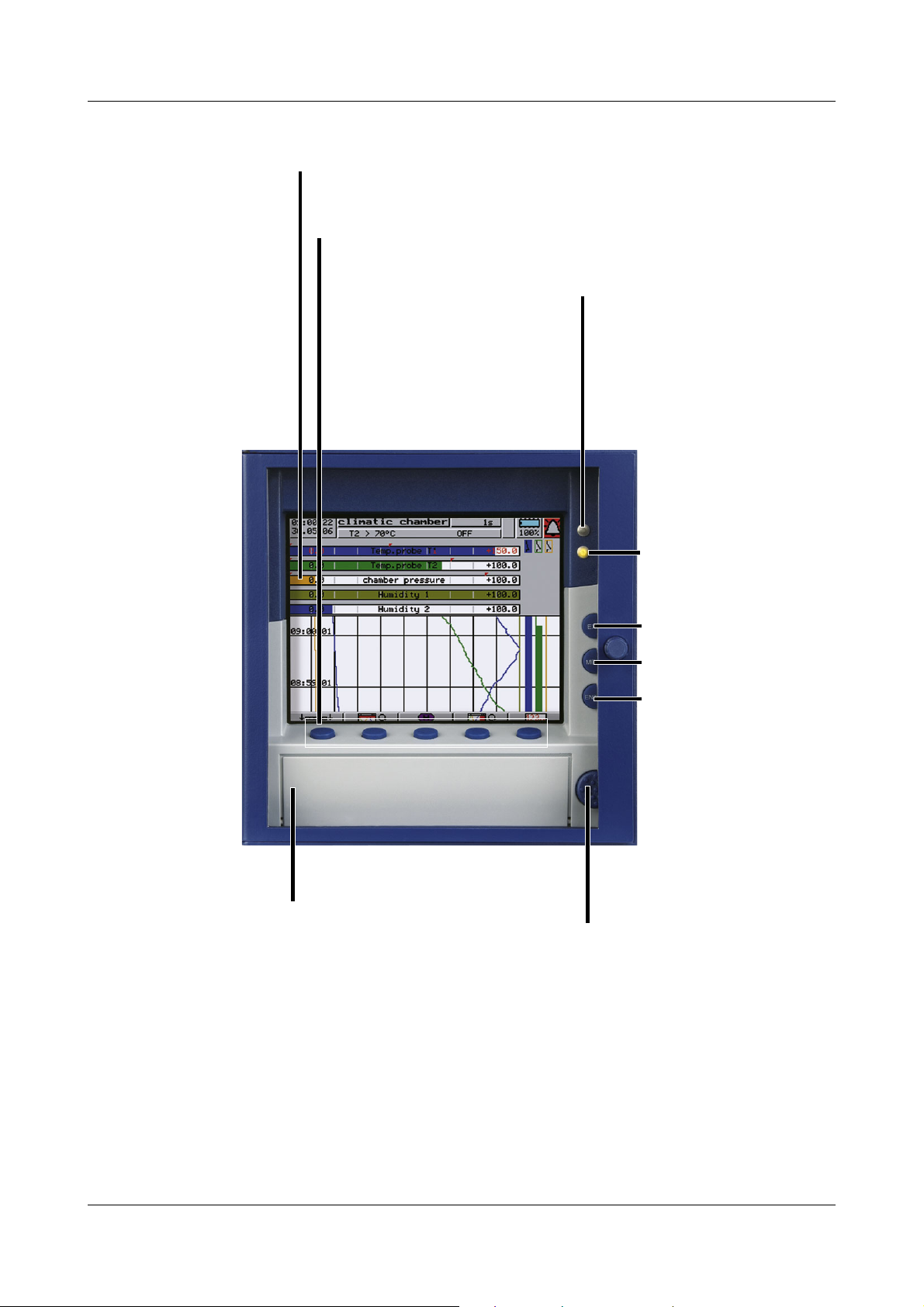
2.1 Displays and controls
Status LED (red)
is on continuously while
an alarm is present
Enter
- select menu item
- enter selection
Menu
return to the basic menu
1
Exit
- previous window
- cancel the
present action
Menu-dependent function keys (softkeys)
screen-dependent functions, represented by text or symbols
Color display
320 x 240 pixels, 27 colors
Cover
for the CompactFlash
®
slot
2
to open the cover of the
CompactFlash slot
Power LED (green)
This is lit continuously as
soon as power is applied.
It blinks when the screen
saver is active.
2 Device description
1
Not from the configuration level if a parameter has already been modified there.
2
CompactFlash® is a registered trademark of the SanDisk Corporation.
The life of the background illumination can be prolonged by
making use of the screen saver.
v Chapter 4 “Configuration parameters”,
Parameterization
Display off
11
Page 12
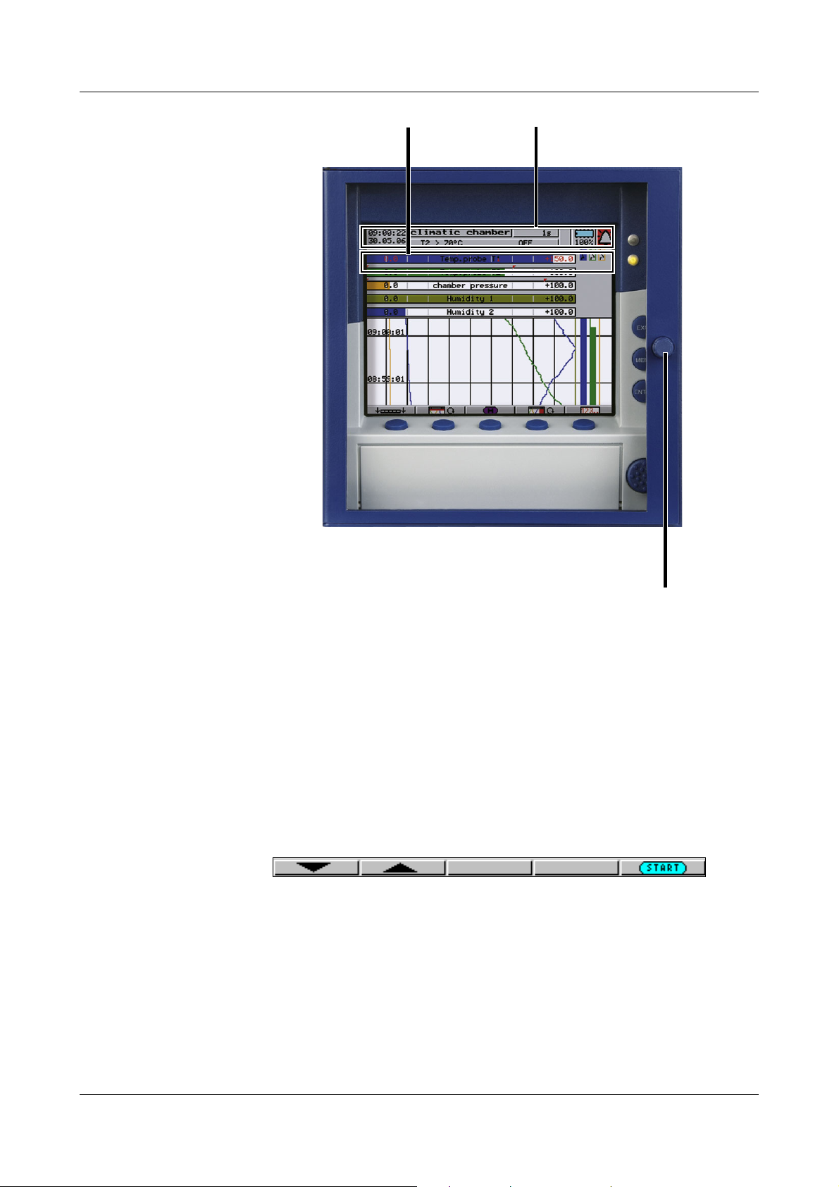
2 Device description
To open or close the door of the
instrument, turn the knob
Status line
Header
Opening and
closing the door
of the
instrument
2.2 Operating principle and graphic elements
Keys The recorder is operated from eight keys. Three of these keys have fixed
Softkeys The functions of the softkeys appear in the bottom line of the display, as
functions, the other five (softkeys) have menu-dependent functions.
v Chapter 2.1 “Displays and controls”
symbols or in plain text.
12
Page 13
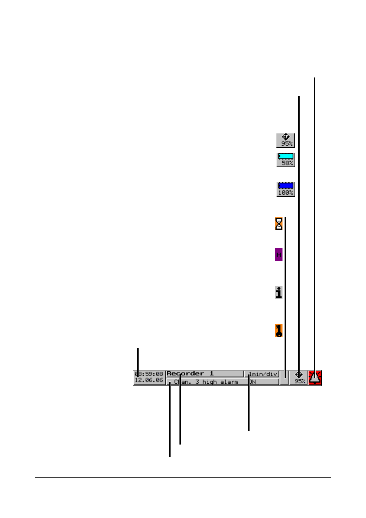
2 Device description
Time & Date
Display of the current time
and date
The egg timer appears whenever the instrument cannot be
operated because it is busy.
The “H” indicates that the measurements which are displayed
are derived from the past (history). The display shows
the data saved in the FLASH memory.
If a fault occurs, an “i” will flash in this position.
In the device info window (v Chapter 3.7 “Device info”)
you can ask for the cause of the fault.
If the keys are inhibited, a key will flash in this position.
Alarm
If an alarm occurs (e.g. out-of-limit), the bell (alarm) will flash in this field.
Shows the last entry in the event list
Instrument name (maximum 16 characters).
Present diagram speed
Background color:
gray = normal operation,
blue = timed operation,
orange = event operation
CF card / internal memory
Shows the free storage of the CompactFlash card or the internal memory, as
a percentage. In the event of a “memory alarm” or a fault on the CF card, the field is
shown with a yellow background and the symbol will flash. The error message
can be checked in the CF card menu (Chapter 3.6 “CompactFlash card”).
Storage capacity of the CF card
Available internal memory for read-out via CF card
(the diagram shows a turquoise-colored memory chip)
Available internal memory (for read-out via interface)
(the diagram shows a dark blue memory chip)
Status line The status line is shown in the top section of the display. It provides
information on important actions and states. The status line is always visible,
irrespective of the level (operation, parameters, configuration).
13
Page 14
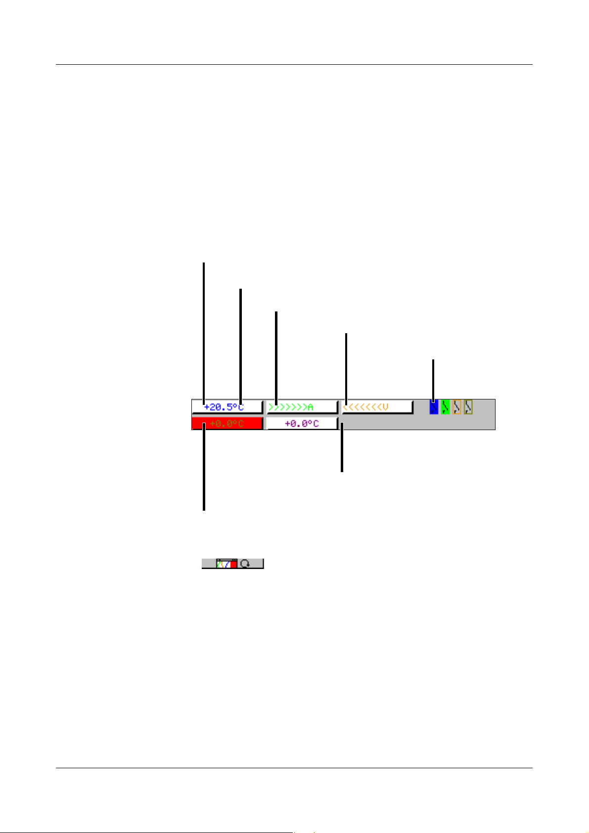
2 Device description
Numerical display
The measurements are shown in numerical form.
OFF
If a channel has been switched off, then
there will be no indication at all.
Unit of measurement
Alarm
If an alarm (e.g. out-of-limit) is present,
the measurement of the channel is shown on a red background.
Overrange
Underrange
(underrange)
State of the
event traces
Channel line
(channel
representation)
The channel line shows the measurements of the active channels and their unit
as
- a measurement
-scale or
-bar graph.
Alternatively, the header can be switched off altogether.
In addition, alarms and out-of-limit conditions are made directly visible,
depending on the display mode.
Example: Measurement (small meas.)
Selection and visual presentation of the channel line can be controlled through
the parameter Parameterization ➔ Diagram view ➔ Channel represent. or by
using the key.
With the help of the parameter Parameterization ➔ Diagram view ➔ Channel
indication ➔ Channel 1 — 6, it is possible to suppress the display of individual
channels in the channel line. This is especially useful for scale or bar graph
display, where more space is needed to show the diagram. The channels that
have been suppressed in the display will nevertheless be recorded, and shown
on the diagram.
2.3 Analog inputs
Internal
analog inputs
The paperless recorder can be equipped with 3 or 6 analog inputs. When
configuring the analog inputs (Chapter 4.2 “Table of configuration
parameters”), these are designated as analog input 1 — 3 (1 — 6).
14
Page 15

2 Device description
2.4 Digital signals (event traces)
Signal types In addition to the four binary inputs (extra code), digital signals generated by
the instrument itself can also be displayed in the six digital traces (event
traces):
signal Description
Binary input 1 — 4 Four binary inputs available as hardware
(extra code)
Logic channel 1 — 6 Channels which are created by using the math
and logic module (extra code required)
Low alarm 1 — 6 Underrange of the channels
Low combination alarm OR linkage of all low alarms
High alarm 1 — 6 Overlimit of channels
High combination alarm OR linkage of all high alarms
Counter/integrator alarm 1 — 6 Limit infringements of counter and
integrator channels (extra code required)
Counter/integrator combination
alarm
Combination alarm OR linkage of all low, high and counter/inegrator
CF card inserted The signal is set when a CF card is inserted in the
Int. mem. alarm/CF card The alarm is triggered when the internal storage
Int. mem. alarm/serial The alarm is triggered when the internal storage
Mem. alarm/CF card The alarm is triggered when the storage memory
Error Alarm when the battery is empty, or the time has
OR linkage of all counter/integrator
alarms (extra code required)
alarms
instrument. It remains active until the card is
removed.
memory available for read-out via the CF card
card has fallen below a certain value
memory available for read-out via the interface
has fallen below a certain value
available on the CF card that has been plugged in
falls below a certain value
plugged in.
to be set.
Chapter 3.7 “Device info”
1
, or no CF card is
1
.
1
.
MODbus flag Control flag, which can be activated through one
of the interfaces.
1
The limit for all memory alarms is the same, and is set by the parameter
Configuration Device data Memory alarm.
15
Page 16
2 Device description
Representation Representation on the screen is as follows:
Representation
as symbol On/off represented as switch:
as diagram Representation as a record over time:
Outputs The digital signals can be used to operate three relays (extra code). The action
can be configured as a break (SPST-NC) or make (SPST-NO) contact
(Configuration ➔ Outputs).
External texts External texts can be called up via four binary inputs or the logic channels. If a
binary input is closed or a logic channel makes a 0-1 transition, then the
preconfigured text will be entered in the event list. Either a standard text or one
of the 18 definable texts can be used. The instrument automatically
supplements the texts in order to distinguish between the appearance and
disappearance of the signal. The external texts are configured on the
instrument, under Configuration ➔ Control functions.
v Chapter 3.5 “Event list”
Event operation The digital signals can be used to activate event operation. In event operation,
the measurements are stored with a storage cycle that is different from normal
operation.
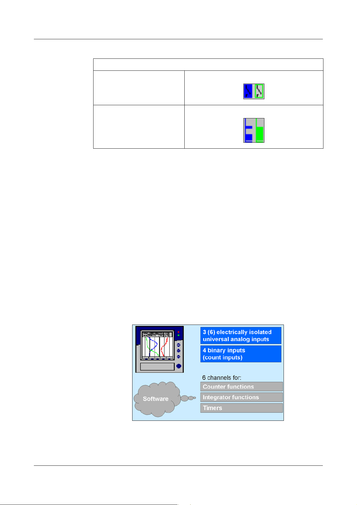
2.5 Counters / integrators / operating time counter
16
These are not electrical measurement inputs (hardware), but channels which
are calculated by the paperless recorder (software).
Page 17

2 Device description
Counters
Counter inputs Any of the digital signals can be used as input signals for the counters.
v Chapter 2.4 “Digital signals (event traces)”
Example:
- binary inputs
- logic channels
-alarms
- memory alarms
- Modbus flag (signal via interface)
Counter
frequency
Evaluation The count pulses can be evaluated (weighted). A down counter can be
30Hz max.
implemented by entering a negative weighting (e.g. weighting factor -1).
Each count change can be documented with an entry in the event list. The
new count is attached to the message.
Integrators
Integrator
inputs
Integrator
time base
Evaluation You can also enter a weighting for the integrators.
Weighting
example
Analog inputs 1 — 3 or 1 — 6 and math channels 1 — 6
sec, min, hr and day
- measurement of flow volume
- input signal of 0 — 20mA (corresponds to 0 — 500 liters/sec)
- time base 1sec
Minimum size
of the input
signal
- weighting 0.001
Result: display of the integration value (volume) in m³.
Entering a threshold value (amount of the threshold value) has the effect that
integration takes place only when the value has been exceeded. No
integration will occur on falling below this value. The advantage of integration
with a threshold value larger than 0 is that possible noise from a transducer
can be suppressed in this way.
If there is an overrange or underrange on an integrator input, then
integration is stopped (the latest valid value is retained), and will
only continue when the input signal is correct again.
17
Page 18

2 Device description
Operating time counter
The operating time counter will count how long a selected binary input or one
of the digital signals is closed (set). The time can be displayed in sec, min, hr
or days.
2.5.1 Reporting period of the counts
After an adjustable time (reporting period), the counts are stored for all
counters/integrators/operating time counters. The counts for the current and
the previous 7 completed reporting periods will be displayed. The following
counter/integrator types are possible:
-periodic
In addition, the time period (between 1 min and 12 hrs) must be selected in
the parameter Period.
-external
In this case, the counter/integrator is updated only when the selected
control signal is active (e.g. binary input is closed). When the control signal
is deactivated (e.g. binary input is opened), the counter/integrator value is
saved and reset to 0.
- daily
-weekly
-monthly
-yearly
-total
- daily, from ... to
The period also has to be selected, by means of the parameters “Daily start
time” and “Daily end time”. The counter/integrator will then be updated
from the start time only. When the end time has been reached, the counter/
integrator value is saved and reset to 0.
2.5.2 Resetting the counters / integrators / operating time counters
Periodic reset There is a reporting period for each counter/integrator/operating time counter.
At the end of this period, the current data (value and time) are saved and the
value reset to 0. Subsequently, the next period can be recorded.
An exception is the totalizer/integrator. It is saved whenever any count/
integration has been completed, but it is not reset to 0. It enables the totalizer
to be evaluated in the evaluation software PCA as well.
18
Page 19

2 Device description
External reset You can configure one control signal for all 6 counters/integrators together,
with the result that the counters/integrators are reset to 0 without any saving
of the previous values. The period for the counter/integrator summation will be
restarted at this point. This means that after the test run of an installation, for
instance, the recording can be freshly started; the test run values that are not
required are eliminated.
v see Page 69 “Generate reset”
Reset from
keys
Reset from
CompactFlash
card menu
Another option for resetting the counter/integrator values is provided at the
parameter level. After entering the password, you can define a value for each
of the 6 channels. The counter/integrator will then be set to this value. When
the value is entered, after editing, a message with the new and the old count is
entered in the event list.
The time period for the counter/integrator summation will not be restarted. The
previous counter/integrator values will also not be saved.
If you wish to save the previous counter/integrator values, you
must execute the function “Update CF incl. counters ...” in the
menu for the CompactFlash card.
In this way, the recording can be freshly started for individual counters/
integrators, e.g. after the test run of an installation; the test run values that are
not required will be eliminated in the process.
You can select a password that is different from that for accessing the
configuration. The password is set up in Configuration ➔ Device data ➔ Code
No. (password) ➔ Reset counter / int.
If, in the menu CompactFlash card, the function CF update incl. counters
is carried out, then the counter states will also be saved and then reset.
v See “CompactFlash card” on Page 50.
2.5.3 Response to instrument reconfiguration
When the instrument is reconfigured, the current counter/integrator reporting
periods remain unaffected. The counter/integrator values will not be reset to 0
and the reporting period will not be restarted.
The values can only be deliberately reset through the
Parameterization menu.
19
Page 20
2 Device description
2.5.4 Response at end of summer time
If a period of less than one hour has been set for counters/
integrators, and the change from summer time to winter time falls
precisely within this period, then the PC evaluation software
(PCA3000) will forcibly set the end time to be the same as the start
time. This prevents a negative period arising, and ensures that
further processing is error-free.
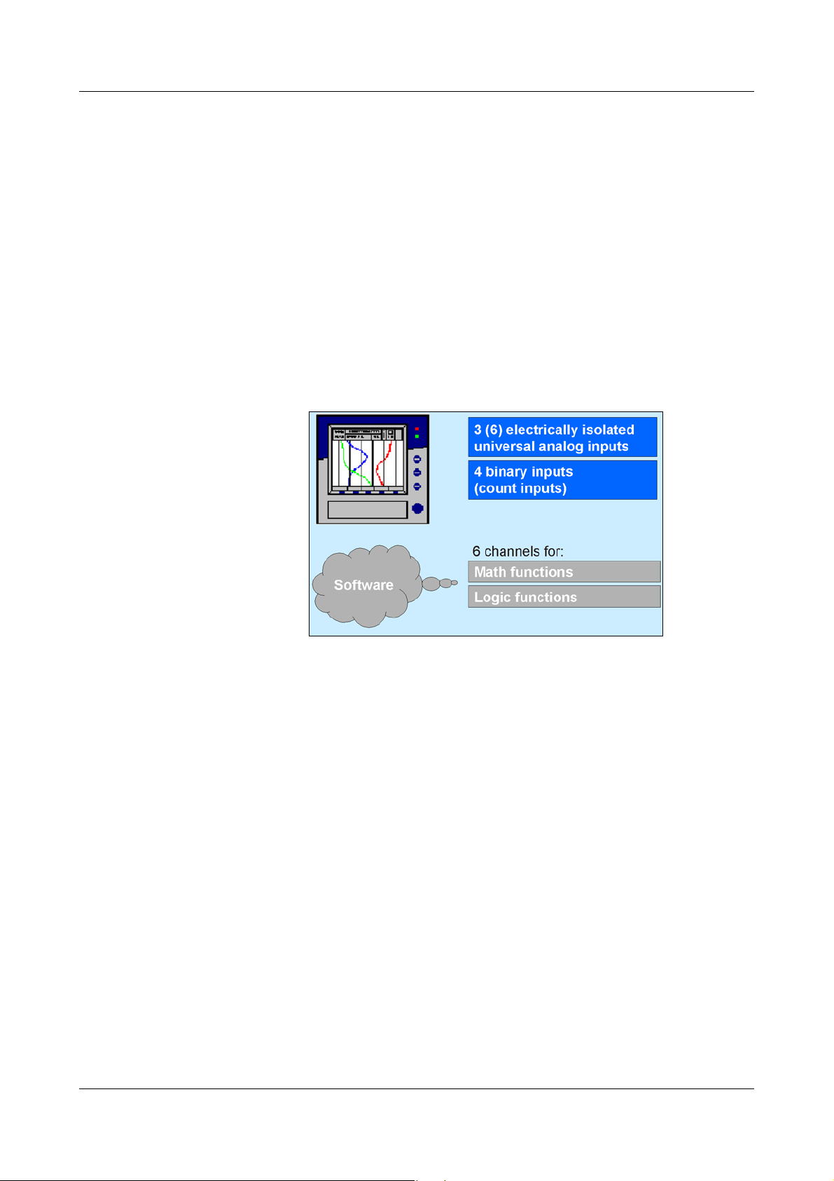
2.6 Math/logic module
The math and logic module is available as an extra code. Like the counter/
integrator/operating time counters, the math and logic module is implemented
as channels that are not available as hardware but are calculated by the
instrument software.
The math and logic module consists of 2 parts:
- the math module for calculating analog values and
- the logic module for calculating Boolean values (0 or 1).
Math module With the help of the math module, measurement inputs can be used for the
calculation of “virtual” math channels.
A total of 6 channels can be recorded (stored) in the instrument. In the
configuration, you will find an option under Configuration
Analog channels Analog channel 1 — 6 Input signal for selecting which
of the analog inputs or math channels should be stored.
If more than 6 channels are to be active in the instrument (e.g. 4 analog inputs
and 3 active math channels), then you can also use the visualization in the
presentation mode “Large digital display (large measurements)” to see the
measurements that are not stored.
v Chapter 3.2.4 “Large digital display (large measurements)”
Recording
20
Page 21

2 Device description
The following variables are used for the formulae:
- analog inputs (AE1 — AE6)
- math channels (MAT1 — MAT6)
- counter/integrator channels (ZI1 — ZI6)
- binary inputs (BE1 — BE4)
-alarms
-errors
- Modbus flag (signal via interface)
- instrument-specific data (only after consultation with the manufacturer)
If counter/integrator values are used for calculation, then please note that their
accuracy is reduced, since, in this case, two different data formats have to be
used for calculation. The counters/integrators are calculated in the doublefloat format, whereas the math module employs a single-float format that
follows the IEEE 754 standard. Nevertheless, it is possible to include these
values in the math module.
The following fixed functions are available:
-difference
-ratio
- relative humidity (psychrometric measurement)
- moving average
For the moving average, the reference channel has to be entered (in most
cases, the analog input number) and the time period (in minutes) for
calculating the moving average.
The following operators and functions are available for the formulae: +, -, *, /,
(, ), SQRT(), MIN(), MAX(), SIN(), COS(), TAN(), **, EXP(),
ABS(), INT(), FRC(), LOG(), LN().
On going above or falling below the scalable values, the math channel is
treated as for “out-of-range”.
The formulae are entered in the PC, in the setup program. The mathematical
formulae cannot be edited by using the keys on the instrument.
For further information, refer to
Chapter 5.9 “Math/logic”
21
Page 22
2 Device description
Logic module You also have up to 6 channels available as logic channels.
As is the case with all the other digital signals, the calculated digital (Boolean)
values can be used for different functions:
- recording in the event traces,
- as a control signal for display switch-off,
- clock time synchronization,
- operating time counter,
- externally controlled counters / integrators
- counter/integr. reset
- event operation and key inhibit,
- for output to a relay and
- as count input for a counter.
The following variables are used for the formulae:
- binary inputs
- logic channels
-alarms
-errors
- Modbus flag (signal via interface)
-TRUE
-FALSE
- device-specific data (only after consultation with the manufacturer)
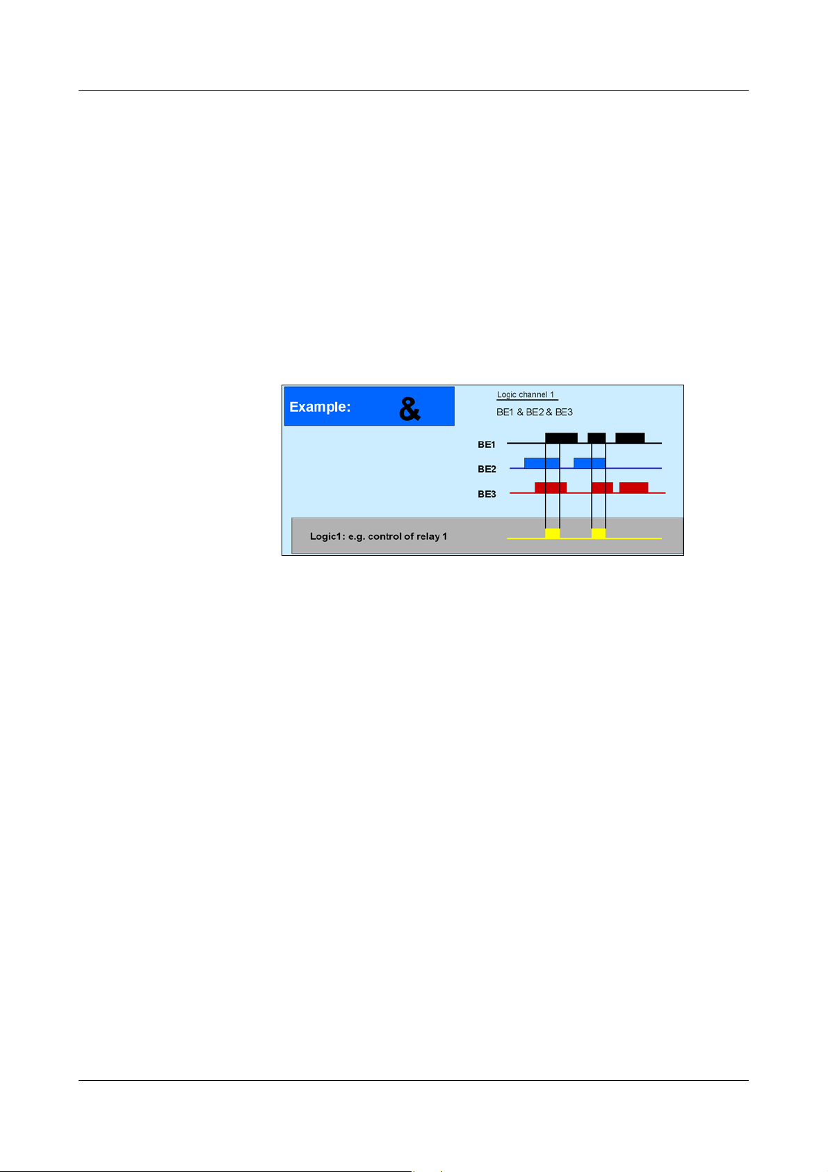
These functions can be used for the formulae:
-! (NOT)
-& (AND)
-| (OR)
-^ (XOR)
- / (rising edge)
- \ (falling edge)
-( (open bracket)
-) (close bracket)
22
For further information, refer to
Chapter 5.9 “Math/logic”
Page 23

2.7 Operating modes
2 Device description
3 operating
modes
The instrument has 3 operating modes:
- normal operation
- timed operation
- event operation
The following settings can, among others, be made for each of the three
operating modes:
-stored value
-storage cycle
Stored value The stored value setting determines what is stored: average, minimum,
maximum or momentary value between two storage cycles, or the peak value
(envelope). The setting “peak value” means that the maximum and minimum
values from the last storage cycle are saved.
Storage cycle The storage cycle determines the interval between two stored values. The
diagram speed corresponds to the storage cycle, which means that with a
storage cycle of 5sec, for example, the stored value is entered in the diagram
every 5sec.
Normal
Normal operation is active whenever event or timed operation is not active.
operation
Timed
operation
For timed operation, a period of time can be defined (up to 24 hrs) within
which a specific stored value and a specific storage cycle are active.
Event operation Event operation is active as long as its control signal (v Chapter 4.2.6
“Configuration - Recording”) is active. Event operation can be used, for
example, to shorten the storage cycle when an alarm is present.
Priority The respective priorities of the operating modes are allocated as follows:
Operating mode Priority
Active
operating mode
Normal
operation
Timed operation average
Event operation high
The active operating mode is shown in the diagram by the background color
for the diagram speed:
Operating mode Color
Normal
operation
Timed operation turquoise
low
gray
Event operation orange
v Chapter 2.2 “Operating principle and graphic elements”
23
Page 24
2 Device description
2.8 Storing data
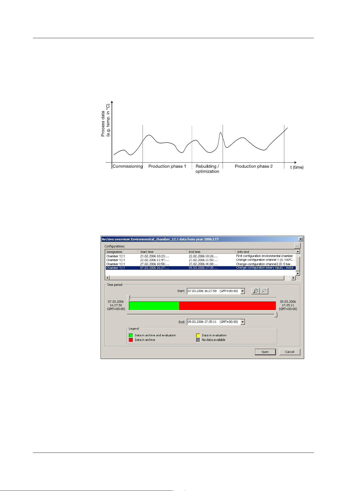
Life-cycle data
management
The integrated life-cycle data management puts users in the position of being
able to save all the process data from the system that is being monitored in an
archive file on their PCs or a server system.
The recovery of configuration-dependent system data, which may be required
for commissioning, maintenance or optimization during the life-cycle of a
system, is now enabled by the associated PC evaluation software (PCA3000)
in a dialog window.
24
Page 25

Operating
principle
2 Device description
The measurements from the analog inputs are acquired continuously in a
250msec sampling cycle, and then stored in the main memory. These
measurements also serve as the basis for limit monitoring.
Main memory
(FLASH
memory)
CompactFlash
card
Data security The data are stored in coded form in a proprietary format. If the CompactFlash
Storage cycle Different storage cycles, ranging from 1sec to 32,767sec can be configured
The data stored in the main memory are regularly copied to the CompactFlash
card in 4 kbyte blocks. The main memory is written to as a ring memory, i.e.
when it is full, the oldest data will automatically be overwritten by new data.
The capacity of the main memory is sufficient for approximately 350,000
measurements. The instrument monitors the capacity of the main memory and
activates the “Memory alarm (internal)” signal if the level falls below a
configurable residual capacity.
For saving the data, CompactFlash cards (industrial grade) can be used with
the following storage capacities: 64/128/256MB.
The instrument monitors the capacity of the CompactFlash card, and activates
the “Memory alarm (CF card)” signal if the level falls below a configurable
residual capacity. This signal can be used, for instance, to operate a relay
(warning signal “Swap CF card”).
card is removed from the instrument, no data will be lost immediately, as these
data are still stored in the FLASH memory. A loss of data will only occur if, after
the CompactFlash card has been removed, the FLASH memory is completely
rewritten as well, and no data have been read out through the interface.
for normal, event and timed operation under “configuration”.
The storage cycle determines the time intervals at which the measurements
are stored.
Stored value Under this parameter, separate configurations are made for normal, event and
timed operation, to decide which value is stored (average, momentary,
minimum, maximum, peak values).
25
Page 26

2 Device description
Recording
duration
The recording duration depends on various factors:
- number of analog channels and event traces being recorded
-storage cycle
- number of events in the event list.
Internal recording duration (without external CF card)
Number of
channels
3approx.
6approx.
Memory
size
1MB
1MB
Storage
cycle
1 min
42.2 days 21.1 days 7 days 17 hours
29.5 days 14.8 days 4.9 days 12 hours
Storage
cycle
30 sec
Storage
cycle
10 sec
Storage
cycle
1 sec
Recording duration with CF card
Number of
channels
3 64 MB 8.8 years 4.4 years 1.5 years 1.8 months
Memory
size
Storage
cycle
1 min
Storage
cycle
30 sec
Storage
cycle
10 sec
Storage
cycle
1 sec
Optimization of
recording
duration
3 128 MB 17.6 years 8.8 years 2.9 years 3.5 months
3 256 MB 35.3 years 17.6 years 5.9 years 7.1 months
6 64 MB 6.2 years 3.1 years 1.0 years 1.2 months
6 128 MB 12.3 years 6.2 years 2.1 years 2.5 months
6 256 MB 24.7 years 12.3 years 4.1 years 4.9 months
The calculation of the recording duration is made for the storage of
momentary, minimum, maximum or average values. If peak values are
recorded, then the times are shorter, since a maximum and minimum value is
recorded each time.
The recording capacity will be further reduced if a large number of event
messages are also stored.
The recording duration can be optimized by process-oriented selection of the
storage cycle.
In normal operation (no error, no alarm, ...) a storage cycle that is as long as
possible (e.g. 60sec, 180sec, …) should be selected, depending on the
particular application.
In the event of an alarm or error, the storage cycle can be shortened via event
operation, with the effect that the measurement data are recorded with a high
time resolution.
26
Page 27

2 Device description
2.9 Read-out of data
In addition to automatic read-out via the external CompactFlash memory card,
measurement data can also be read out through one of the interfaces (RS232,
RS485, setup, Ethernet).
Both read-out options (card/interface) work in parallel. For this reason, there
are also two “digital signals”, which indicate when the available storage space
has fallen below a certain configurable value.
Memory alarm The limit for alarms can be set by the parameter Configuration ➔ Device data
➔ Memory alarm in the configuration level.
The parameter Configuration ➔ Memory upload can be used to determine
which storage space indication should be shown in the status line. The “digital
signals” for storage space detection function independently of the indication in
the status line.
Digital signals IntMemAlm/CF
If this signal is set, it means that no data have been fetched by the CF card for
a long time, and the available capacity of the internal memory has fallen below
the configured level.
IntMemAlm/ser
If this signal is set, it means that no data have been fetched by the interface for
a long time, and the available capacity of the internal memory has fallen below
the configured level.
MemAlmCFcard
If this signal is set, it means that not enough space is avialable on the CF card.
The program PCA3000 can help here. Use PCA3000 to read in the data, save
them to the hard disk on a network, and free up the space on the CF card.
Alternatively, you can use a new CF card.
Data lost A loss of data is only imminent if all three of the above signals are set.
Read-out via
interface
Use the PCA Communications Server software (PCC) to read out
measurement data via the serial, setup or Ethernet interface. The software has
been developed especially for the paperless recorder.
v Please refer to the Operating Manual 59500 for further information.
Use the same archive (in the PC) for reading out via the interface
as for reading out with the CF card. This saves having to put
together data from different files at a later date.
2.10 Evaluating data
Please use the PC Evaluation Software (PCA3000) for evaluating the data on
the PC. The software has been developed especially for the paperless
recorder.
v Please refer to the Operating Manual 59498 for further information.
27
Page 28
2 Device description
Device nameAnalog channelsCounters / integratorsEvent traces
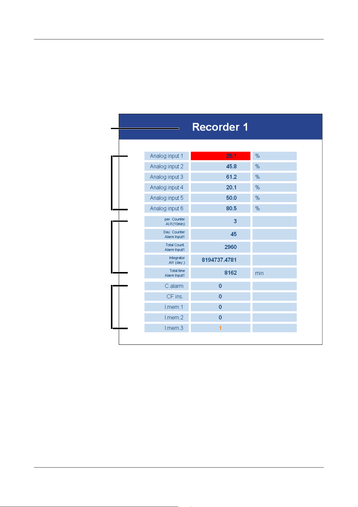
2.11 Webserver
If the paperless recorder is equipped with the extra code “Ethernet interface”,
and the device-internal Ethernet software (“Ethernet version“) has the number
183.02.03 or higher, then the paperless recorder has an inbuilt webserver. The
webserver can be started by entering the IP address in an Internet browser on
the PC (e.g. http://10.10.90.45).
The variables that are shown are acquired and displayed automatically by the
webserver. The latest data are read out of the instrument every 5 seconds. Any
limit infringements show a red background. A maximum of 6 channels (analog
or math channels), up to 6 counters or integrators, and a maximum of 6 event
traces.
28
Page 29

2 Device description
Display of ... Activated through menu ...
Device name Configuration - Instrument data - Device name
Analog or math channels Configuration - Recording - Analog channels
Counters or integrators Configuration - Counter/integrator
Event traces Configuration - Recording - Event traces
Only the activated signals will be displayed.
The information about the “Ethernet version” can be found in the “Device info”
menu.
v Chapter 3.7 “Device info”
H
Since the paperless recorder is only polled by the Internet browser every 5 seconds, it is possible that, for instance, the PCC data transfer software takes
over control of the paperless recorder during this interval. After securing the data, PCC will end access to the recorder, so that the Internet browser can read
out data again.
Only 1 PC (client) at a time can access the device (server) via the
Ethernet interface.
29
Page 30

2 Device description
30
Page 31

3 Operation and visualization
After starting up the paperless recorder by switching on the supply (power
ON), you will see the start logo.
During screen build-up, the recorder is initialized with the data of the last
configuration.
After the initialization phase, the measurement diagram
(visualization level) is displayed.
By using the setup program, an individual start logo (bitmap with a
maximum of 16 colors) can be loaded into the instrument, through
the function Extras
Start screen.
31
Page 32

3 Operation and visualization
h Select the required level
h Enter selection with E
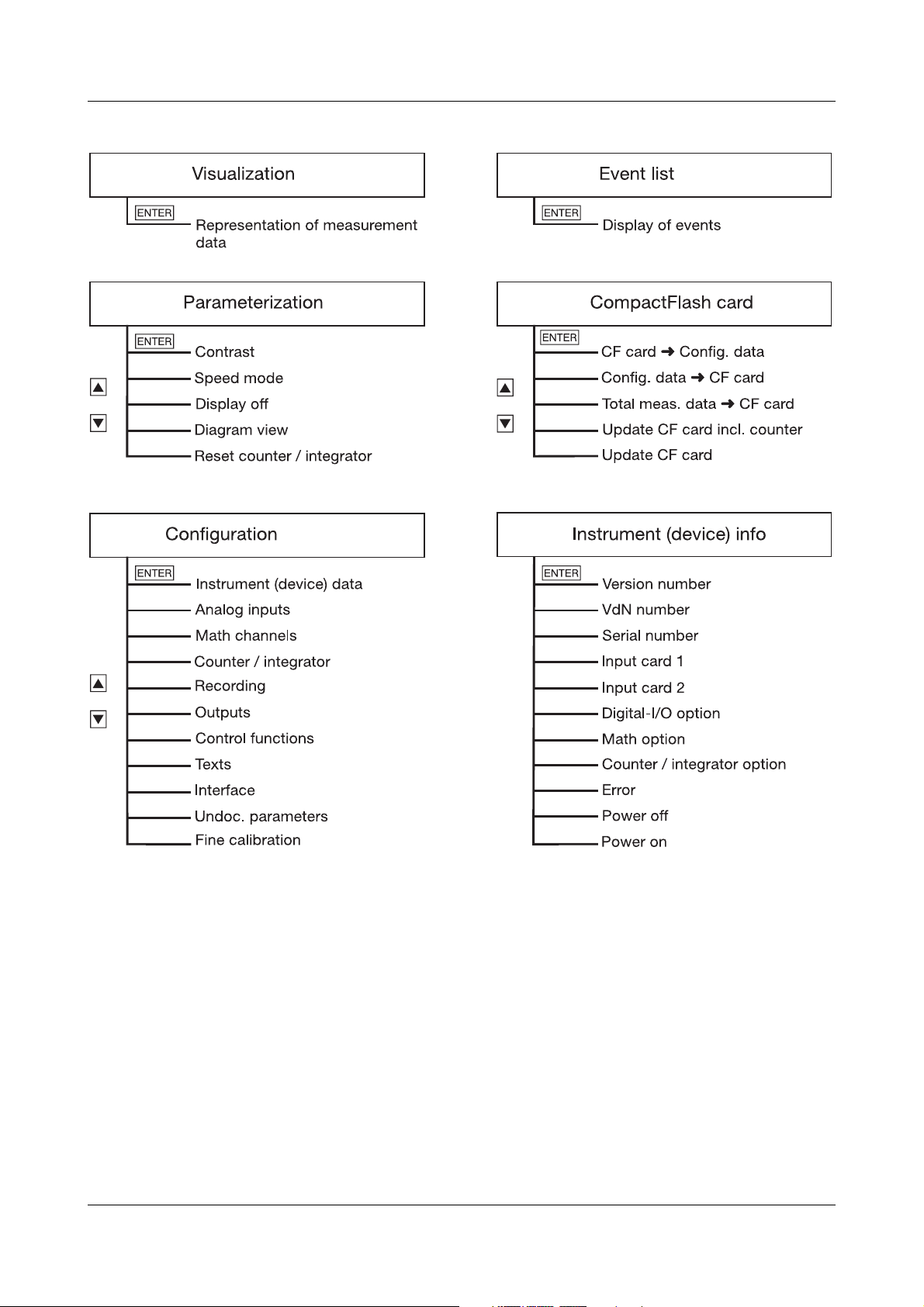
3.1 Basic menu
The basic menu is the central point from which the various instrument levels
branch out.
The following levels are available:
v Chapter 3.2 “Visualization”
v Chapter 3.3 “Parameterization”
v Chapter 3.4 “Configuration”
v Chapter 3.5 “Event list”
v Chapter 3.6 “CompactFlash card”
v Chapter 3.7 “Device info”
32
The basic menu is displayed after pressing the
1
Not from the configuration level,
if a parameter has already been modified there.
Mkey
1
.
Page 33

3.2 Visualization
Evaluation of the stored
measurement data (history)
Hide function keys (softkeys)
Alter signal type (representation)
- analog inputs
- analog inputs and
event traces
Alter channel representation (header)
- diagram representation with digital display (small
measurements)
- diagram representation with scaling
- diagram representation with bar graph
- large digital display (large measurements)
- diagram representation (header switched off)
Show event
list
Show counters / integrators / operating
time counters
As already mentioned in Chapter 2.2 “Operating principle and graphic
elements”, the softkeys are arranged at the bottom of the screen. They change
their function according to the menu and are shown as symbols or plain text.
3 Operation and visualization
If the paperless recorder is equipped with “Counters/Integrators” (extra code),
the symbol for indicating the counts will now appear below the softkey on the
right, the symbol for showing the event list is shifted to the counter display.
33
Page 34

3 Operation and visualization
- current measurements of the analog inputs, including dimensional unit
- measurement on a red background out of limit
3.2.1 Diagram representation with digital display (small measurements)
Diagram representation can be reached from the basic menu, by calling up the
“Visualization” menu or by pressing the
D key.
By using the parameter Parameterization ➔ Diagram view ➔ Signal type (or
the button), it is possible to select whether, in addition to the
analog channels, the event traces are to be displayed as well. The contents of
the header are determined by means of the parameter Parameterization ➔
Diagram view ➔ Channel representation (or the button).
34
Page 35

3 Operation and visualization
Scaling start of the selected channel
Lower limit index of the selected channel
(no display when alarm is off)
Upper limit index
(no display when alarm
is off)
Current measurement
Channel name
Scaling end
of the selected channel
Scaling start of the selected channel
Lower limit index of the selected channel
(no display when alarm is off)
Upper limit index
(no display when alarm
is off)
Scaling end
of the selected channel
Current measurement
Channel name
3.2.2 Diagram representation with scaling
Which scaling (on which channel) is to be displayed can be selected through
the parameter Parameterization ➔ Diagram view ➔ Channel indication.
3.2.3 Diagram representation with bar graph
Use the parameter Parameterization ➔ Diagram view ➔ Channel indication to
select which bar graph (from which channel) is to be displayed.
35
Page 36

3 Operation and visualization
3.2.4 Large digital display (large measurements)
This display type is limited to the digital display.
If more than 6 signals are active (for instance, 6 analog inputs and 3 math
channels), the button is switched into the display. It can be used
to switch between the individual signals.
- recorded analog channels (channels selected through the parameter
Configuration
- all analog inputs
- all math channels
Recording Analog channels)
36
Page 37

3 Operation and visualization
3.2.5 Curve representation (header switched off)
This display type is limited to the curve display.
37
Page 38

3 Operation and visualization
Cursor (violet)
Current zoom
(magnification)
Scroll forwards fast
(one screen)
Scroll forwards slowly (one pixel line)
History
activated
Switch to
softkey functions
Zoom/Search
Date and time of measurements at
the cursor position
Scroll backwards slowly (one pixel line)
Scroll backwards fast (one screen)
Measurement at the
cursor position
3.2.6 Evaluation of the stored measurement data
History The softkey function changes during evaluation. In addition, the current zoom
factor and cursor position (date and time) will be shown.
Scroll operation
Using these softkeys, the measurement data display can be scrolled (shifted)
on the screen within the measurement data stored in the internal memory.
38
Measurement acquisition remains active during history
representation.
Page 39

3 Operation and visualization
Cursor (violet)
Zoom +
Position cursor on time (selectable)
Switch to
softkey
function
“Scroll”
Only for peak-value acquisition:
switch channel line between MIN
and MAX display
Zoom -
Scrolling backwards within the internally stored measurement data
is possible up to the last changeover from summer time to normal
time.
Zoom If the zoom factor has to be adjusted, or specific times have to be searched,
then it is necessary to switch the softkey functions.
h Press softkey
The degree of compression of the measurement data on the screen is given as
a ratio in steps (1:1, 1:2, 1:5, 1:10, 1:20, 1:50 and 1:100).
For instance, a ratio of 1:100 means that 1 screen pixel corresponds to 100
measurements, i.e. only every hundreth stored measurement is displayed.
39
Page 40

3 Operation and visualization
Cursor
positioning
Peak-value
acquisition
After activating the button, the following dialog appears for positioning the
cursor on a specific time:
After entering the date and time and activating , the cursor is
positioned on the selected time.
If no measurement data have been stored for the selected time, then the
cursor is positioned on the next possible time.
If the data have been recorded in the “peak value” mode, then two different
measurements (one minimum and one maximum value) may be displayed
graphically for one instant of time (storage cycle). Using the key,
it is possible to switch between minimum and maximum value display within
the “measurement” display mode.
Function key Channel line
Minimum
Maximum
Peak value acquisition is programmed (activated) through the parameters:
- Configuration ➔ Measurement storage ➔ Normal display ➔ Stored value
- Configuration ➔ Measurement storage ➔ Event operation ➔ Stored value
- Configuration ➔ Measurement storage ➔ Timed operation ➔ Stored value
For further information about the “measurement” display mode, see Chapter
3.2.1 “Diagram representation with digital display (small measurements)” and
Chapter 3.2.4 “Large digital display (large measurements)”.
40
Page 41

3 Operation and visualization
Show curves
Expanded representation
Programmed
alarm limit
was exceeded
Overrange
3.2.7 Counters / integrators / operating time
Count display is optionally available (extra code). If it is available, a screen
such as the following will appear after the softkey has been pressed, in which
the current counts are shown in a numerical form.
Press the softkey to activate the expanded representation.
41
Page 42

3 Operation and visualization
Normal representation
Event list
see
Chapter 3.5
“Event list”
Current count
Concluded reporting period
Show next concluded
reporting period
The last 7 concluded reporting periods can be
shown, one after another, by pressing the key.
Expanded
representation
42
Page 43

3.3 Parameterization
3 Operation and visualization
The Parameter level is available to set
-contrast,
- speed indication
-display off
- diagram view and
- counter/integrator reset.
All parameters are selected using the and
or and keys.
Contrast The contrast of the screen can be set here. This ensures that the screen is
always highly legible, even under difficult light conditions.
Speed
indication
“mm/h”, “time/div” or “storage cycle” is selected here for the speed display in
the diagram.
Example: a diagram speed of 1hr/div correspond to approx. 22mm/hr.
43
Page 44

3 Operation and visualization
Display off
(screen saving)
Diagram view Diagram view ➔ Signal type
Switch-off event = waiting time
For screen saving, a time between 0 and 32,767min can be set under the
parameter “Waiting time”. If no key on the recorder is operated during this
time, then the screen goes dark. The power LED blinks during screen saving.
Screen saving can be canceled by pressing any key on the recorder.
If 0min is set, then screen saving is deactivated.
Switch-off event = control signal
In this case, screen saving is performed through one binary input (extra code)
or a different control signal. The binary input is selected via the parameter
“Control signal”.
As long as the signal is present, the screen remains switched off. A waiting
time is not allowed for.
Screen saving is deactivated when “Off” is selected.
Only one type of screen saving can be active at any time.
The representation mode of the measurements and event traces are
determined here:
- analog inputs
- analog inputs and event traces.
Diagram view ➔ Channel representation
The contents of the channel bar is selected here:
- small measuremenst
-scaling
-bar graph
- large measurements
-switched off.
Diagram view ➔ Channel indication
The channels which are displayed in the channel line, in the representation
mode “Small measurement“ “Scaling” and “Bar graph” are selected here.
Diagram view ➔ Paper perforations
This can only be selected if only the analog channels and no event traces are
displayed. When Yes is set, paper perforations appear in the diagram, thus
giving the picture the appearance of a conventional chart recorder.
44
Page 45

3 Operation and visualization
Counter/
integrator
reset
After the password has been successfully entered, the counts for each of the 6
channels can be set to 0 or a defined value in this menu.
When a value has been entered (confirm with the
new and old count is entered in the event list. The time period for the counter/
integrator summation will not be restarted. The previous counter/integrator
values will also not be saved. If you wish to do so, you have to carry out
Update CF card incl. counters in the CompactFlash card menu before
resetting.
In this way, the recording can be freshly started for counters/integrators, e.g.
after the test run of an installation. The test run values that are not required will
be eliminated in the process.
You can select a password that is different from that for accessing the
configuration. The default value is also 09200.
The password can be set in the menu Configuration ➔ Device data ➔ Code
No. (password) ➔ Reset counter/int.
E key), a message with the
45
Page 46

3 Operation and visualization
Window title
Parameter is inhibited
Parameter can be selected/edited
Current setting
3.4 Configuration
When you call up the configuration level, you will be asked to enter the
password (factory setting: 09200). This also serves to prevent unauthorized
alteration of the configuration.
After entering the password, a warning appears, which must be
acknowledged with the
v Chapter 3.10 “Code number (password query)”
E key.
Window
technology
As for the other levels, the configuration principle is also based on menu-led
window technology. Individual menu items can be selected in the windows.
The window title describes the contents of the window.
If a menu item is selected, a further window is opened with new menu items,
until the required parameter is finally reached. If several windows are open, the
window title assists in orientation.
46
Page 47

3 Operation and visualization
The configuration of the recorder is sub-divided into the following levels:
v Chapter 4 “Configuration parameters”
3.5 Event list
Events Various events can initiate texts which are incorporated in the event list and
saved to the internal memory or CF card. Events may include:
- alarms triggered by out-of-limit conditions on individual channels,
Event
definition
Te xt
assignment
Freely definable
texts
- external texts triggered through binary inputs or logic channels,
- system messages (e.g. power ON/OFF, summer/winter time changeover),
- count-up of a counter,
- any message text of up to 20 characters that was transmitted to the device
via one of the interfaces.
For all events, except for system messages, it is possible to configure
whether:
- the message text is to be included in the event list,
- the device-internal standard text
- or one of the texts (see below) is used.
The texts (standard texts or 18 freely definable texts) are assigned to events at
the operating level “Configuration” (v Chapter 4 “Configuration parameters”).
18 texts can be freely defined, up to a length of 20 characters.
47
Page 48

3 Operation and visualization
Standard texts The recorder offers standard texts as listed in the following table:
Standard text Comment
Channelx low alarm ON
Channelx low alarm OFF
Channelx high alarm ON
Channelx high alarm OFF
Counter/int. alarm x ON
Counter/int. alarm x OFF
Binary input y ON
Binary input y OFF
Logic channel y ON
Logic channel y OFF
Counter x: yx = counter channel number
Power ON
Power OFF
Data lost
Summer time start
Summer time end
New configuration
Counter/int. x reset from y to z
“Text 1 — 18” 18 freely definable texts
x = channel number
y = input number
y = counter value (9 digits)
x = counter/int. channel number
y = old counter/int.value (9 digits)
z = new counter/int. value (9 digits)
with 20 characters each
Supplementary
text
The recorder automatically supplements the texts by “ON” or “OFF” in order to
distinguish between the appearance and disappearance of the signal.
Example:
Standard text Supplementary
text
Binary input 2 ON Binary input 2 ON
Binary input 2 OFF Binary input 2 OFF
Entry in event list
48
Page 49

3 Operation and visualization
h Select operating level Event list
h Enter selection with E
jump back directly into diagram presentation
Basic menu ➔
Event list
The event list is called up via the basic menu:
Event list
49
Page 50

3 Operation and visualization
h Select operating level CompactFlash card
h Enter selection with E
3.6 CompactFlash card
Automatic
storage of
measurement
data
Loading and
saving the
configuration
data
Basic menu ➔
CompactFlash
card
The data stored in the measurement data memory (FLASH) of the paperless
recorder are saved at regular intervals to the CompactFlash card
instrument. The PC evaluation program (v Chapter 7 “PC programs”) reads
the data from the CF card and provides user-friendly functions for evaluation.
The configuration data can be downloaded from the CF card and saved to the
CF card. A configuration can thus be copied from one instrument to another,
or it can be transferred from and to the PC setup program.
Only one configuration file can be saved to the CF card at any
time. If there is a configuration on a CF card, this will be
overwritten without any further query through the function
CompactFlash card ➔ Config. data➔CF card.
The CompactFlash menu is called up via the basic menu:
1
in the
The functions
- Update CF incl. counters ...,
- Compl. meas. data ➔ CF,
- Config. data ➔ CF card and
- CF card ➔ Config. data
are protected against unauthorized access by a password query (factory
setting: 09200).
1
PC Card access made available by CSM FAT File System
Copyright © 1997-2002 CSM GmbH Filderstadt, Germany
50
Page 51

CompactFlash
Residual capacity of CF card in percent
Background flashes on error (e. g. “CF
card full”, “no CF card”,
or in the event of a memory alarm
Start action
The configuration data are read from the CF card
The configuration data are written to the CF card
All measurement data in the memory are written to CF card
Measurement data not yet saved are written to the CF card.
Select action
Counter/integrator reporting periods are concluded and
written to the CF card, together with the measurement data
not yet saved. Counters/integrators are reset (to 0) and
restarted.
card
3 Operation and visualization
The function CF card Update reads out data that have not been
read out yet. After read-out, the data are marked as read in the
recorder.
The function Total meas. data
the internal memory, including those that had already been read
out.
CF card reads all the data from
51
Page 52

3 Operation and visualization
Status
messages
Status messages from the CompactFlash manager are shown in the
corresponding action window. The following status messages are possible:
Status message Description
CF CARD UPDATED Directly before removing the CF card from the
instrument, it is necessary to call up Update CF
card so that all measurement data up to the time
of removal are contained on the CF card. The data
not yet stored since the last automatic saving are
written to the CF card.
NO CF CARD If there is no CF card in the instrument, the CF
card symbol flashes in the status line.
CF CARD FAULT An error has occurred while writing to the CF card.
The CF card is faulty.
Remedy:
Insert new (FAT16-formatted) CF card.
CF CARD FULL If the CF card is full, the CF card symbol flashes in
the status line. No more data will be written to the
CF card.
Remedy:
Insert a blank CF card before the measurement
data memory of the recorder is also full. If this is
not done, measurement data will be lost.
NO CONFIG. FILE ON CF An attempt was made to read a configuration from
the CF card, but there is no suitable configuration
file on the CF card.
52
Page 53

3.7 Device info
h Select operating level Device info
h Enter selection with E
The device info window displays general information about the instrument. It
also includes the errors “Battery empty” and “Data lost”. If one of the
instrument errors occur, the info symbol flashes in the status line.
3 Operation and visualization
Basic menu ➔
Device info
The device info is called up from the basic menu:
Device info
53
Page 54

3 Operation and visualization
- This menu also includes the version number (e.g. 208.01.04). This is the
version number of the device software. It is important because some
functions are only available from a certain version number onwards.
- If the “Digital I/O option” is available (Yes), then the recorder also includes
an RS232/RS485 interface.
- If the Ethernet interface is available, then the field “Vers. No. Ethernet”
includes a number combination (e.g. 183.02.02). If this option is not
available, the field is filled with “-”.
Error The following errors may occur:
Error Description
none no error in instrument
Data lost A discharge of the battery or storage capacitor
occurred during the last lengthy power
interruption.
The clock was set to 01.01.00 00:00:00.
Remedy:
Reset the time (v Chapter 4.2.2 “Configuration Instrument (device) data”) and use a new
CF card for data storage.
Battery empty This message appears on instruments with a
lithium battery, when the time was reset after a
loss of data but the battery is still empty
Please return the instrument to the supplier for a
change of battery.
Data may be lost after separating the instrument from the supply:
after more than 10 years (on instruments with a lithium battery) or
after approx. 2 weeks (at ambient temperature 15 to 25°C) with a
storage capacitor.
54
Page 55

3 Operation and visualization
Switch to character set matrix
Select the character to be altered using the softkeys
Accept character
Select new character
3.8 Text entry
Entry options The configurable texts can be entered either through the setup program or on
the instrument itself. This section describes the entry on the instrument.
Character
selection
The display below is shown when a text (e. g. Configuration ➔ Text s) has been
selected at the configuration level for editing using
E.
After the character to be altered has been selected and the switch made to
character set matrix, the cursor is positioned on the current character in the
character set matrix.
Character entry The softkeys change their function, as can be seen from the picture below:
After the entire text has been entered, it can either be accepted or all
alterations canceled.
h Enter text with
or
h cancel text entry with
E
D
55
Page 56

3 Operation and visualization
Increase (+1) or
decrease (-1) selected
digit or change the sign
Select the digit to
be altered
Alter the number
of decimal places
3.9 Entering values
The softkeys are also used to enter values in the instrument – the example
shows fine calibration being carried out.
56
The sign can only be altered if the value is not “0”. This means that
you cannot start the value entry with an alteration of the sign if the
current value is “0”.
The entry can be concluded with
E or canceled with D.
Page 57

3 Operation and visualization
Increase (+1) or
decrease (-1) selected
digit
Select the digit to
be altered
3.10 Code number (password query)
The following functions are protected ex-factory against unauthorized access
by a password query:
-the Configuration menu
-parts of the CompactFlash card menu
-the Parameterization ➔ Reset counter / int. menu.
The factory default setting for the passwords is 09200.
You can also use a password to secure access to the recorder via one of the
interfaces (with the exception of the setup interface). However, the factory
default setting here is 0 (no password query). If you enter a value other than 0,
please take into account that this number must also be sent to the recorder by
an attached communications program.
Further information about the password query for the interfaces
can be found in the Interface description 59482.
Password query
All passwords can be programmed differently (see Chapter 4.2.2
“Configuration - Instrument (device) data”).
When you have finished the entry (e.g. +09200), use the
Use
D if you want to cancel the password query and quit the menu.
E key to confirm it.
57
Page 58

3 Operation and visualization
Password query
in the
configuration
menu
After the password has been entered in the Configuration menu, an additional
security query will appear. You will only be able to gain access to the
parameters when you have confirmed the the query with
E.
58
Page 59

4.1 Operating example
4 Configuration parameters
1
If required, the code number must be entered here
(factory setting: 09200)
2
Cancel entry; the old settings are retained
3
Accept entry
59
Page 60

4 Configuration parameters
4.2 Table of configuration parameters
The table below lists all the instrument parameters. The order in which the
parameters are explained corresponds to the order in which they appear on
the instrument (in the menu structure).
The first column describes the path to the particular parameter, via the menus
and windows.
The second column lists the possible settings for the parameters or the
possible selections. The factory default setting in this column is shown bold.
The third column contains a description of the parameter, or the possible
selections, if the parameter and its function or selection is not self-evident.
4.2.1 Parameterization
Parameter Value/Selection Description
Contrast Parameterization
➔ Contrast
Speed indication Parameterization
➔ Speed indic. mode
Switch-off event Parameterization
➔ Display off
➔ Switch-off event
Waiting time Parameterization
➔ Display off
➔ Waiting time
Control signal Parameterization
➔ Display off
➔ Ctrl signal
Signal type Parameterization
➔ Diagram view
➔ Signal type
0—16 — 31 Display contrast
in mm/h,
time/div,
storage rate
Waiting time,
Cntrl signal
0 — 32767min Time after which the
Off,
Bin. inp. 1 — 4,
Logic channel 1 — 6,
Low alarm 1 — 6,
Low comb.al.,
High alarm 1 — 6,
High comb.al.,
Count/Int/Al 1 — 6,
C/i. comb.al.,
Comb. alarm,
CF inserted,
IntMemAlmCF,
IntMemAlmSer,
MemAlmCFcard,
Error, Modbus flag,
Analog inp.,
Analog&Event
The selected display mode
is shown in the diagram
representation
The type of display
switch-off (screen saving)
is selected here
display is switched off. Any
key stroke will re-activate
the display. The parameter
can only be entered if the
parameter Switch-off event
is set to “Waiting time”.
0 = display not off
If one of the 4 binary inputs
(extra code) or one of the
other control signals is set
to “off” and activated, then
the display will be switched
off. The parameter can only
be entered if the parameter
Switch-off event is set to
“Control signal”.
This determines which
measurements are
graphically displayed
60
Page 61

4 Configuration parameters
Parameter Value/Selection Description
Channel
representation
Channel indication Parameterization
Paper perforations Parameterization
Counter/int. reset Parameterization
Parameterization
➔ Diagram view
➔ Chan. represent.
➔ Diagram view
➔ Channel indication
➔ Channel 1 — 6
➔ Diagram view
➔ Paper perforations
➔ Reset counter/int.
➔ Channel 1 — 6
Meas. small,
Scaling
Bar graph
Meas. large,
Off
Yes,
No
No,
Yes
-999999999 to 0 to
+999999999
This determines the
contents of the channel
line (header)
“Yes” means that the
selected channels are
shown in the header
“Yes” means that paper
perforations are shown
within the graphic display,
on the left and right
margins of the screen.
Paper perforations can
only be activated and
shown if no event traces
have been selected (signal
type = analog input)
The start value for the
counter or integrator can
be entered here. The
current value is not saved.
Count changes are
documented in the event
list.
v Chapter 3.3
“Parameterization”
If the password query
is active (password “Reset
counter/int.” > 0), the start
values can only be set if
the password has been
entered correctly.
61
Page 62

4 Configuration parameters
4.2.2 Configuration - Instrument (device) data
Parameter Value/Selection Description
Device name Configuration
➔ Device data
➔ Device name
Date Configuration
➔ Device data
➔ Date and time
➔ Date
Time Configuration
➔ Device data
➔ Date and time
➔ Time
Time
synchronization
Summer time
(switch)
Summer time
(start date)
Summer time
(start time)
Summer time
(end date)
Summer time
(end time)
Configuration
➔ Device data
➔ Date and time
➔ Time
synchroniz.
Configuration
➔ Device data
➔ Summer time
➔ Switch
Configuration
➔ Device data
➔ Summer time
➔ Start date
Configuration
➔ Device data
➔ Summer time
➔ Start time
Configuration
➔ Device data
➔ Summer time
➔ End date
Configuration
➔ Device data
➔ Summer time
➔ End time
16 characters
any date Entry of the current
date
any time Entry of the current
time
Off,
Bin. inp. 1 — 4,
Logic channel 1 — 6,
Low alarm 1 — 6,
Low comb.al.,
High alarm 1 — 6,
High comb.al.,
Count/Int/Al 1 — 6,
C/i. comb.al.,
Comb. alarm,
CF inserted,
IntMemAlmCF,
IntMemAlmSer,
MemAlmCFcard,
Error, Modbus flag,
Off,
User timed,
Automatic
any date Can only be set if
any time Can only be set if
any date Can only be set if
any time Can only be set if
With the help of this
parameter (function), the
system clocks of several
paperless recoders can be
simultaneously
synchronized.
When a binary input has
been selected and is
activated (transition from
“Low” to “High”), then the
time can be synchronized.
The seconds are decisive
in the time change. They
are used for rounding the
time up or down.
Example:
12:55:29 -> 12:55:00
12:55:30 -> 12:56:00
Automatic:
2:00 hrs or 3:00 hrs on the
last Sunday in March or
October
switch is set
to user timed
switch is set
to user timed
switch is set
to user timed
switch is set
to user timed
62
Page 63

4 Configuration parameters
Parameter Value/Selection Description
Language Configuration
➔ Device data
➔ Language
Temperature unit Configuration
➔ Device data
➔ Temperature unit
Memory upload Configuration
➔ Device data
➔ Memory upload
Memory alarm Configuration
➔ Device data
➔ Memory alarm
Code number for
the configuration
Code number:
CompactFlash
card menu
(CF code No.)
Code number:
Reset counter/int.
Code number:
RS232/RS485 +
Ethernet
Factory setting Configuration
Configuration
➔ Device data
➔ Code No. (password)
➔ Configuration
Configuration
➔ Device data
➔ Code No. (password)
➔ CF manager
Configuration
➔ Device data
➔ Code No. (password)
➔ Reset counter/int.
Configuration
➔ Device data
➔ Code No. (password)
➔ RS232/RS485+
Ethernet
➔ Device data
➔ Enter defaults
German, English, French,
Dutch, Spanish, Italian,
Hungarian, Czech,
Swedish, Polish, Danish,
Finnish, Portuguese,
Russian
°C, °F
via CF card,
via RSxxx
0—10 — 100% The signals
00000 — 09200 — 09999 Code number for
00000 — 09200 — 09999 Code number for
00000 — 09200 — 09999 Code number to delete
00000 — 09999 Code number as
No, Yes Yes = enter factory default
You can determine how
data are mainly to be
uploaded. The value for the
available capacity (shown
in the status line) will vary
according to the selection.
“IntMemAlmCF”,
“IntMemAlmInterf” and
“MemAlmCFcard” are
activated when the residual
capacity of the internal
memory or the CF card has
fallen to this value. Chapter
2.4 “Digital signals (event
traces)”
configuration level;
0000 = off
The data saved in the
FLASH memory will be
deleted when the
configuration is changed.
menu functions
CompactFlash card;
0000 = off
individual counts;
0000 = off
protection against
unauthorized access to
data via one of the
interfaces;
0000 = off
setting (after entry, the
parameter automatically
returns to No)
63
Page 64

4 Configuration parameters
Parameter Value/Selection Description
Enable options Configuration
➔ Device data
➔ Enable options
Enable options:
Computed code
No.
Enable options:
Authorization code
Device-info text In the setup program, the parameter Configuration level Device data can be used
Configuration
➔ Device data
➔ Enable options
➔ Computed
code No.
Configuration
➔ Device data
➔ Enable options
➔ Authorization
code
to enter a device-Info text (max. 500 characters). The text is saved together with the
measurement data, and can be displayed in the PCA3000 evaluation software. The
text will not be shown on the instrument.
(display a code No.) The value that is shown
Authorization code
entry
This parameter is used to
enable additional
functions, e.g. the math/
logic module and counter/
integrator. The parameter
will not be available if all
the recorder functions have
been enabled.
here must be passed on to
the manufacturer. The
manufacturer will then
send you the release code.
Enter the authorization
code (release code) you
received here.
4.2.3 Configuration - Analog inputs
Parameter Value/Selection Description
Sensor Configuration
➔ Analog inputs
➔ Analog input 1—6
➔ Sensor
Linearization Configuration
➔ Analog inputs
➔ Analog input 1—6
➔ Linearization
Connection circuit Configuration
➔ Analog inputs
➔ Analog input 1—6
➔ Connection circuit
Cold junction Configuration
➔ Analog inputs
➔ Analog input 1—6
➔ Cold junction
Off,
RTD,
Thermocouple,
Current,
Voltage
Linear, Pt100, Pt100 JIS,
Pt100 GOST, Pt500,
Pt1000, Pt50, Ni100,
Cu50, Cu100, Fe-Con J,
NiCr-Con E, NiCr-Ni K,
NiCrSi N, Cu-Con T,
PtRh-PtRh B,
PtRh-Pt R, PtRh-Pt S,
Cu-Con U, Fe-Con L,
W3W25Re D,
W5W26Re C,
ChromelCopel
2 — 4 wire Only for sensor type:
Intern.Pt100
Extern. const
Depending on the sensor
that was selected, only the
relevant parameters can be
selected when configuring
the analog input.
resistance thermometer
64
Page 65

4 Configuration parameters
Parameter Value/Selection Description
External
cold junction
temperature
Range
start
Range
end
Start temperature Configuration
End temperature Configuration
Scaling start Configuration
Scaling end Configuration
Filter constant Configuration
Configuration
➔ Analog inputs
➔ Analog input 1—6
➔ Ext. CJ temp.
Configuration
➔ Analog inputs
➔ Analog input 1—6
➔ Range start
Configuration
➔ Analog inputs
➔ Analog input 1—6
➔ Range end
➔ Analog inputs
➔ Analog input 1—6
➔ Start
temperature
➔ Analog inputs
➔ Analog input 1—6
➔ End temperature
➔ Analog inputs
➔ Analog input 1—6
➔ Scaling start
➔ Analog inputs
➔ Analog input 1—6
➔ Scaling end
➔ Analog inputs
➔ Analog input 1—6
➔ Filter constant
-50 to +150°C External cold junction
temperature for
thermocouples
any value
0mA
any value
20mA
any value Only for sensor: current or
voltage with linearization,
resistance thermometer,
thermocouple.
Only for signals that have
not yet been linearized.
any value Only for sensor: current or
voltage with linearization,
resistance thermometer,
thermocouple.
Only for signals that have
not yet been linearized.
-99999 to 0 to +99999
-99999 to +100 to +99999
0.0 — 0.1 —10.0s
65
Page 66

4 Configuration parameters
4.2.4 Configuration - Math channels
Parameter Value/Selection Description
Scaling start Configuration
➔ Math channels
➔ Math channel 1 — 6
➔ Scaling start
Scaling end Configuration
➔ Math channels
➔ Math channel 1 — 6
➔ Scaling end
4.2.5 Configuration - Counter/integrator (extra code)
Parameter Value/Selection Description
Channel Configuration
➔ Counter/integrator
➔ Counter/int.chans.
Function Configuration
➔ Counter/integrator
➔ Counter/int.chans.
➔ Channel 1 — 6
➔ Function
Type Configuration
➔ Counter/integrator
➔ Counter/int.chans.
➔ Channel 1 — 6
➔ Ty pe
Input signal Configuration
➔ Counter/integrator
➔ Counter/int.chans.
➔ Channel — 6
➔ Input signal
-99999 to 0 to +99999 Scaling start of a math
channel.
The setup progam is used
to determine what is
involved in a math channel.
-99999 to +100 to +99999 Scaling end of a math
channel.
The setup progam is used
to determine what is
involved in a math channel.
1 — 6 Select channel for which
the subsequent
parameters are to be
configured.
Off,
Counter
Integrator,
Oper.time
Periodic,
External,
Daily,
Weekly,
Monthly,
Aearly,
Total,
DailyFrom-To
Off,
Bin. inp. 1 — 4,
Logic channel 1 — 6,
Low alarm 1 — 6,
Low comb.al.,
High alarm 1 — 6,
High comb.al.,
Count/Int/Al 1 — 6,
C/i. comb.al.,
Comb. alarm,
CF inserted,
IntMemAlmCF,
IntMemAlmSer,
MemAlmCFcard,
Error, Modbus flag,
First select the required
function.
v Chapter 2.5 “Counters /
integrators / operating
time counter”
Reporting period.
Select here when the count
value is to be stored and
reset.
The parameter can only be
programmed if “Counter”
or “Operating time” has
been selected under
Function.
Please select which event
is to be counted.
66
Page 67

4 Configuration parameters
Parameter Value/Selection Description
Input signal Configuration
➔ Counter/integrator
➔ Counter/int.chans.
➔ Channel 1 — 6
➔ Input signal
Weighting Configuration
➔ Counter/integrator
➔ Counter/int.chans.
➔ Channel 1 — 6
➔ Weighting
Time base Configuration
➔ Counter/integrator
➔ Counter/int.chans.
➔ Channel 1 — 6
➔ Time base
Threshold value Configuration
➔ Counter/integrator
➔ Counter/int.chans.
➔ Channel 1 — 6
➔ Threshold
value
Channel name
(line 1)
Channel name
(line 2)
Configuration
➔ Counter/integrator
➔ Counter/int.chans.
➔ Channel 1 — 6
➔ Channel name
Configuration
➔ Counter/integrator
➔ Counter/int.chans.
➔ Channel 1 — 6
➔ Channel name
Analog inp. 1 — 3(6),
Math channel 1 — 6
-99999 to +1 to +99999 Select the weighting factor
Second,
Minute,
Hour,
Day
0 — 99999 The parameter can only be
12 characters
Counter/int.
12 characters
Channel 1 — 6
The parameter can only be
programmed if “Integrator”
has been selected under
Function.
Please select which input
is to be integrated.
here.
If, for instance, 0.001 is
entered, then a conversion
can be achieved from liter/
sec to m³. If a negative
weighting factor is entered
(e.g. -1), the counter will
count down.
The parameter can only be
programmed if “Integrator”
or “Operating time” has
been selected under
Function.
Integrator:
Select the time base for
integrating the selected
channel (second, for
example, if your sensor
generates a signal in liters/
second).
Operating time:
Select the unit used for
counting the time.
programmed if “Integrator”
has been selected under
Function.
Enter the threshold value
that has to be exceeded
for integration to proceed.
The text that has been
entered appears together
with line 2 and the current
count on the recorder
screen (visualization and
event list).
v Chapter 3.2.7
“Counters / integrators /
operating time”
The text that has been
entered appears together
with line 1 and the current
count on the recorder
screen (visualization and
event list).
67
Page 68

4 Configuration parameters
Parameter Value/Selection Description
Unit Configuration
➔ Counter/integrator
➔ Counter/int.chans.
➔ Channel 1 — 6
➔ Unit
Decimal place Configuration
➔ Counter/integrator
➔ Counter/int.chans.
➔ Channel 1 — 6
➔ Decimal place
Counter text Configuration
➔ Counter/integrator
➔ Counter/int.chans.
➔ Channel 1 — 6
➔ Counter text
Alarm Configuration
➔ Counter/integrator
➔ Counter/int.chans.
➔ Channel 1 — 6
➔ Alarm
Limit value Configuration
➔ Counter/integrator
➔ Counter/int.chans.
➔ Channel 1 — 6
➔ Alarm
Alarm text Configuration
➔ Counter/integrator
➔ Counter/int.chans.
➔ Channel 1 — 6
➔ Alarm
Synchroniz.
time
Period Configuration
Configuration
➔ Counter/integrator
➔ Synchronizat. time
➔ Counter/integrator
➔ Period
➔ Alarm
➔ Limit
➔ Alarm text
5 characters Enter the unit which is
displayed on the recorder
screen, together with the
entered text and the
current count.
Automatic,
X.XXXX, XX.XXX,
XXX.XX, XXXX.X,
XXXXX.
Standard text,
Text 1 — 18 ,
No text
Off,
Activated
-99999 to 100 to +99999 An alarm is triggered when
Standard text,
Text 1 — 18 ,
No text
any time
(00:00:00)
1min, 2min, 3min, 4min,
5min, 10min, 15min,
30min, 1h, 2h, 3h, 4h, 6h,
8h, 12h
Specify the decimal place
for displaying the count on
the recorder screen.
The text selected here will
appear in the status line
and the event list if the
counter is incremented
(decremented).
the limit is infringed. Using
the parameter Weighting, it
is possible to differentiate
between going above or
below the limit (positive
weighting factor = alarm on
going above the limit)
On going above/below the
limit, the text selected here
will appear in the status
line and the event list.
Please enter the time at
which the daily, weekly,
monthly or yearly counter/
integrator value is to be
saved.
Only programmable, if the
parameter Type is set to
“periodic” on at least one
counter/integrator.
The counter/integrator
values are saved at the
selected interval.
68
Page 69

4 Configuration parameters
Parameter Value/Selection Description
Ext. Ctrl signal Configuration
➔ Counter/integrator
➔ Ext. ctrl signal
Weekday Configuration
➔ Counter/integrator
➔ Weekday
Daily start time Configuration
➔ Counter/integrator
➔ Daily start time
Daily end time Configuration
➔ Counter/integrator
➔ Daily end time
Generate reset Configuration
➔ Counter/integrator
➔ Generate reset
Bin. inp. 1 — 4,
Logic channel 1 — 6,
Low alarm 1 — 6,
Low comb.al.,
High alarm 1 — 6,
High comb.al.,
Count/Int/Al 1 — 6,
C/i. comb.al.,
Comb. alarm,
CF inserted,
IntMemAlmCF,
IntMemAlmSer,
MemAlmCFcard,
Error, Modbus flag,
Monday,
Tuesday,
Wednesday,
Thursday,
Friday,
Saturday,
Sunday
any time
(06:00:00)
any time
(18:00:00)
Off,
Bin. inp. 1 — 4,
Logic channel 1 — 6,
Low alarm 1 — 6,
Low com.al.,
High alarm 1 — 6,
High comb.al.,
Count/Int/Al 1 — 6,
C/i. comb.al.,
Comb. alarm,
CF inserted,
IntMemAlmCF,
IntMemAlmSer,
MemAlmCFcard,
Error, Modbus flag,
Only programmable, if the
parameter Type is set to
“external” on at least one
counter/integrator.
Summation of the counter/
integrator values will only
take place if the selected
digital signal is set to “1”.
When changing to “0”, the
values will be saved and
reset.
Only programmable, if the
parameter Type is set to
“Weekly” on at least one
counter/integrator.
The counter/integrator
values are saved on the
selected day on reaching
the synchronizing time.
Only programmable, if the
parameter Type is set to
“Daily from-to” on at least
one counter/integrator.
Only programmable, if the
parameter Type is set to
“Daily from-to” on at least
one counter/integrator.
Here you can determine
the event which will reset
all counter and integrator
counts (without saving).
v Page 19
“External reset”
69
Page 70

4 Configuration parameters
4.2.6 Configuration - Recording
Parameter Value/Selection Description
Analog channels
Input signal Configuration
➔ Recording
➔ Analog channels
➔ Analog channel 1 — 6
➔ Input signal
Channel name Configuration
➔ Recording
➔ Analog channels
➔ Analog channel 1 — 6
➔ Channel name
Unit Configuration
➔ Recording
➔ Analog channels
➔ Analog channel 1 — 6
➔ Unit
Decimal place Configuration
➔ Recording
➔ Analog channels
➔ Analog channel 1 — 6
➔ Decimal place
Line width Configuration
➔ Recording
➔ Analog channels
➔ Analog channel 1 — 6
➔ Line width
Alarm Configuration
➔ Recording
➔ Analog channels
➔ Analog channel 1 — 6
➔ Alarm
➔ Alarm
Low limit Configuration
➔ Recording
➔ Analog channels
➔ Analog channel 1 — 6
➔ Alarm
➔ Low limit
High limit Configuration
➔ Recording
➔ Analog channels
➔ Analog channel 1 — 6
➔ Alarm
➔ High limit
Analog input 1 — 6,
Math channel 1 — 6
16 characters
Analog channel 1 — 6
5 characters
%
Automatic,
X.XXXX, XX.XXX,
XXX.XX, XXXX.X,
XXXXX.
Thin,
Thick
Off,
Activated
-99999 to
-99999 to 0 to +99999
0 to +99999
Select which channel is to
be recorded (stored).
The channel name is
shown in the channel line
(header) for bar graph and
scaling.
Automatic: representation
with maximum resolution
Line width of the
measurement curve within
the graphical display
70
Page 71

4 Configuration parameters
Parameter Value/Selection Description
Differential Configuration
➔ Recording
➔ Analog channels
➔ Analog channel 1 — 6
➔ Alarm
➔ Differential
(1) = Low limit
(2) = High limit
(3) = Differential
-99999 to 0 to +99999
Text Low alarm Configuration
➔ Recording
➔ Analog channels
➔ Analog channel 1 — 6
➔ Alarm
➔ Te xt
Text High alarm Configuration
➔ Recording
➔ Analog channels
➔ Analog channel 1 — 6
➔ Alarms
➔ Te xt
Alarm delay Configuration
➔ Recording
➔ Analog channels
➔ Analog channel 1 — 6
➔ Alarms
➔ Alarm delay
Low alarm
High alarm
Standard text,
Text 1 — 18 ,
No text
Standard text,
Text 1 — 18,
No text
0 — 32767s Alarm delay is activated at
v Chapter 3.5 “Event list”
v Configuration ➔ Texts,
Page 74
a value > 0.
When activated, an alarm
will only be generated
when it has been present
for at least as long as it
takes for the set time to
elapse.
71
Page 72

4 Configuration parameters
Parameter Value/Selection Description
Event traces
Input signal Configuration
➔ Recording
➔ Event traces
➔ Event traces 1 — 6
➔ Input signal
Trace designation Configuration
➔ Recording
➔ Event traces
➔ Event traces 1 — 4
➔ Trace design.
Memory status:
Normal operation
Stored value:
Normal operation
Storage cycle:
Normal operation
Start time:
Timed operation
Configuration
➔ Recording
➔ Normal operation
➔ Memory status
Configuration
➔ Recording
➔ Normal operation
➔ Stored value
Configuration
➔ Recording
➔ Normal operation
➔ Storage cycle
Configuration
➔ Recording
➔ Timed operation
➔ Start time
Off,
Bin. inp. 1 — 4,
Logic channel 1 — 6,
Low alarm 1 — 6,
Low comb.al.,
High alarm 1 — 6,
High comb.al,
Count/Int/Al 1 — 6,
C/i. comb.al.,
Comb. alarm,
CF inserted,
IntMemAlmCF,
IntMemAlmSer,
MemAlmCFcard,
Error, Modbus flag,
7 characters
BE 1 — 4
Operating modes
Off,
On
Average val.,
Instant val.,
Minimum,
Maximum,
Peak value
1—60 — 32767s v Chapter 2.7 “Operating
any time Off when
The event (digital signal)
which is to be recorded is
assigned to an event trace
here.
Event traces 5 and 6 are
switched off in the factory
setting.
v Chapter 2.7 “Operating
modes”
Chapter 2.8 “Storing
data”
modes”
Chapter 2.8 “Storing
data”
Start time = End time
End time:
Timed operation
Stored value:
Timed operation
72
Configuration
➔ Recording
➔ Timed operation
➔ End time
Configuration
➔ Recording
➔ Timed operation
➔ Stored value
any time
Average val.,
Instant val.,
Minimum,
Maximum,
Peak value
v Chapter 2.7 “Operating
modes”
Chapter 2.8 “Storing
data”
Page 73

4 Configuration parameters
Parameter Value/Selection Description
Storage cycle:
Timed operation
Control signal:
Event operation
Stored value:
Event operation
Storage cycle:
Event operation
Configuration
➔ Recording
➔ Timed operation
➔ Storage cycle
Configuration
➔ Recording
➔ Event operation
➔ Control signal
Configuration
➔ Recording
➔ Event operation
➔ Stored value
Configuration
➔ Recording
➔ Event operation
➔ Storage cycle
1—5 — 32767s v Chapter 2.7 “Operating
modes”
Chapter 2.8 “Storing
data”
Off,
Bin. inp. 1 — 4,
Logic channel 1 — 6,
Low alarm 1 — 6,
Low comb.al.,
High alarm 1 — 6,
High comb.al.,
Count/Int/Al 1 — 6,
C/i. comb.al.,
Comb. alarm,
CF inserted,
IntMemAlmCF,
IntMemAlmSer,
MemAlmCFcard,
Error, Modbus flag,
Average val.,
Instant val.,
Minimum,
Maximum,
Peak value
1—5 — 32767s v Chapter 2.7 “Operating
If the configured signal is
active, the instrument will
switch to event operation.
v Chapter 2.7 “Operating
modes”
Chapter 2.8 “Storing
data”
modes”
Chapter 2.8 “Storing
data”
4.2.7 Configuration - Outputs (extra code)
Parameter Value/Selection Description
Action of
outputs
Control signal:
Outputs
Configuration
➔ Outputs
➔ Relay K1 — K3,
➔ Action
Configuration
➔ Outputs
➔ Relay K1 — K3,
➔ Control signal
Off,
make (SPST-NO),
break (SPST-NC)
Off,
Bin. inp. 1 — 4,
Logic channel 1 — 6,
Low alarm 1 — 6,
Low comb.al.,
High alarm 1 — 6,
High comb.al.,
Count/Int/Al 1 — 6,
C/i. comb.al.,
Comb. alarm,
CF inserted,
IntMemAlmCF,
IntMemAlmSer,
MemAlmCFcard,
Error, Modbus flag
As standard, relay K1 is
configured as break (SPSTNO), K2 and K3 are
inactive.
The configured signal is
output to the relay.
The default setting for K1 is
Error.
73
Page 74

4 Configuration parameters
4.2.8 Configuration - Control functions
Parameter Value/Selection Description
External texts:
Binary input 1 — 4
External texts:
Logic channel
1—6
Key inhibit Configuration
Configuration
➔ Control functions
➔ External texts
➔ Binary input
1…4
Configuration
➔ Control functions
➔ External texts
➔ Logic channel
1—6
➔ Control functions
➔ Key inhibit
Standard text,
Text 1 — 18,
No text
Standard text,
Text 1 — 18,
No text
Off,
Bin. inp. 1 — 4,
Logic channel 1 — 6,
Low alarm 1 — 6,
Low comb.al.,
High alarm 1 — 6,
High comb.al.,
Count/Int/Al 1 — 6,
C/i. comb.al.,
Comb. alarm,
CF inserted,
IntMemAlmCF,
IntMemAlmSer,
MemAlmCFcard,
Error, Modbus flag,
v Chapter 3.5 “Event list”
v Chapter 4.2.9
“Configuration - Texts”
Can only be used if the
“Math/logic module”
option is available.
v Chapter 3.5 “Event list”
v Chapter 4.2.9
“Configuration - Texts”
The keys will be locked as
soon as the selected
signal is activated
4.2.9 Configuration - Texts
Parameter Value/Selection Description
Te xt s Configuration
➔ Te xt s
➔ Te xt1 — 1 8
20 characters
Tex t 1 — 1 8
74
Page 75

4 Configuration parameters
4.2.10Configuration - Interfaces
Parameter Value/Selection Description
Serial interface
Interface type Configuration
➔ Interfaces
➔ RS232/RS485
➔ Interface type
Protocol Configuration
➔ Interfaces
➔ RS232/RS485
➔ Protocol
Baud rate Configuration
➔ Interfaces
➔ RS232/RS485
➔ Baud rate
Data format Configuration
➔ Interfaces
➔ RS232/RS485
➔ Data format
Device address Configuration
➔ Interfaces
➔ RS232/RS485
➔ Device address
Min. response time Configuration
➔ Interfaces
➔ RS232/RS485
➔
Min. response time
IP address Configuration
➔ Interfaces
➔ Ethernet
➔ IP address
Subnet mask Configuration
➔ Interfaces
➔ Ethernet
➔ Subnet mask
Gateway Configuration
➔ Interfaces
➔ Ethernet
➔ Gateway
RS232,
RS485
MODbus,
Jbus
9600 bps,
19200 bps,
38400 bps
8-1-none,
8-1-odd,
8-1-even,
8-2-none
1 —254
0 —500ms
Ethernet interface
000.000.000.000 …
192.168.000.010 …
255.255.255.255
000.000.000.000 …
255.255.000.000 …
255.255.255.255
000.000.000.000 …
255.255.255.255
Parameters for the serial
interface (extra code)
The IP address for the
recorder is set here.
The subnet mask is set
here.
Devices are combined into
subnets through the subnet mask. All devices
whose IP address, when
AND-linked, is identical to
the subnet mask, belong to
one subnet and can thus
communicate with each
other.
The address for the
standard gateway is set
here. Devices that do not
belong to a subnet can
communicate through the
standard gateway.
75
Page 76

4 Configuration parameters
4.2.11Configuration - Undocumented parameters
Parameter Value/Selection Description
Undocumented
parameter 1 — 40
4.2.12Configuration - Fine calibration
Parameter Value/Selection Description
Calibration status Configuration
Actual start value Configuration
Set start value Configuration
Actual end value Configuration
Set end value Configuration
Configuration
➔ Undoc. parameter
➔ Par. 1 — 40
➔ Fine calibration
➔ Analog input 1 — 6
➔ Calibration status
➔ Fine calibration
➔ Analog input 1 — 6
➔ Actual start value
➔ Fine calibration
➔ Analog input 1 — 6
➔ Set start value
➔ Fine calibration
➔ Analog input 1 — 6
➔ Actual end value
➔ Fine calibration
➔ Analog input 1 — 6
➔ Set end value
These parameters are
intended for customerspecific adaptation.
Alteration to the settings
may only be carried on the
express instruction of the
equipment manufacturer.
Off,
On
-99999 to 0 to +99999 Start value for
-99999 to 0 to +99999 Start value for
-99999 to 1000 to +99999 End value for
-99999 to 1000 to +99999 End value for
A calibration (adjustment)
of the analog
measurements can be
activated here. The
adjustment is carried out
using a linear equation.
actual line.
Only active when
calibration status = On.
target line.
Only active when
calibration status = On.
actual line.
Only active when
calibration status = On.
target line.
Only active when
calibration status = On.
76
Systematic errors, such as those caused by an unsuitable probe
mounting, for example, can be compensated through fine
calibration.
Example:
A sensor covers temperatures from 200 to 300°C.
It is built into a tunnel oven so unfavorably that it always indicates
10°C less than the temperature of the oven contents. The incorrect
measurement can be corrected through fine calibration.
Actual start value : 200°C
Set start value : 210°C
Actual end value : 300°C
Set end value : 310°C
Page 77

The setup program is used for the easy creation of configuration files, and to
configure the instruments from a PC.
5.1 Hardware and software requirements
The following hardware and software requirements have to be met for
installing and operating the setup program:
5 Setup program
Minimum
configuration
- Intel Pentium
-Microsoft Windows
1
III or higher,
2
NT4.0 (SP6a), 2000 or XP,
- 128Mbyte main memory,
-CD drive,
-mouse,
- one free serial interface or network connection, or CompactFlash memory
cards (depending on the type of data transmission to the paperless
recorder), and
- 120Mbyte available on hard disk.
In addition, the following items are required for communication between the
PC and the recorder, such as:
- reader/writer for CompactFlash memory card or
- PC interface cable including adapter (only when using the setup interface)
or
- serial interface cable (when using the RS232 or RS485 interface) or
- network connection (when using the Ethernet connection).
Recommended
configuration
- Intel Pentium 4
- Windows XP or 2000
- 512Mbyte main memory
- 2Gbyte free space on hard disk for data
1
Intel and Pentium are registered trademarks of Intel Corporation
2
Microsoft and Windows are registered trademarks
of Microsoft Corporation
77
Page 78

5 Setup program
5.2 Installation
Run the
installation
program
Program start h Start the setup program by selecting the entry “Setup program ...“ in the
h Start Microsoft Windows
If Microsoft Windows has already been started, all Windows
programs must be shut down before installing the setup program.
h Insert the CD into the drive, then close the drive.
After the CD has been inserted, the installation program will start
automatically. If not, proceed as follows:
h Start the file “Launch.exe” in the main directory of the CD.
The installation program will lead you through the rest of the installation with
screen messages.
If no valid license number is entered during the installation, the
setup program will remain fully functional for 30 days. After this
time, the data transmission, data storage and printout functions
will be disabled.
chosen program folder.
When the software has just been installed for the first time, there will not yet be
a query of the user name and password. In the menu Extras, the query at the
start of the program can be activated by the function Renew log-in / Alter
password.
The activation of the log-in function can be used to distinguish between the
user types “Specialist” and “Maintenance”. These two users have different
access rights with regard to the functions in the setup program.
v “Renew log-in / Alter password” on page 101
v Chapter 6 “Rights”
If the query is active, proceed as follows:
h Log in.
Please note that not all functions are available to all users.
78
Page 79

5.3 User interface
Menu bar
To ol b ar
Working area
Connection status
Teleservice
5 Setup program
Menu bar The individual functions of the setup program can be started by using the
Toolbar The toolbar contains selected functions of the menu bar. They can be started
menu bar.
v Chapter 5.8 “Menu functions”
from the left mouse button. If you rest the mouse pointer on one of the icons
(tool tips), you will see the function title after a short delay.
79
Page 80

5 Setup program
Shifting the
toolbar
The position of the toolbar can be changed, if desired.
h Move the mouse pointer between two icon groups.
h Press the left mouse button.
h Keeping the left mouse button pressed, drag the toolbar to the required
position.
h Now release the mouse button.
Possible positions are:
- the left or right window border (vertical orientation),
- below the menu bar (horizontal orientation),
- at the bottom edge, above the user details (horizontal orientation) or
- any position (in own window - horizontal orientation).
Working area Here you are provided with an overview of the current settings of a
configuration file.
v Chapter 5.4 “Configuration”
Connection
status
Te le se r vic e Using Teleservice, you can view the latest data from the paperless recorder
In the “Connection status” line you can check whether a connection to a
device has been established, and which interface data are being used. The
line can be made visible or hidden through Window ➔ Connection status.
Example: No connection
Example: Connection to a device
The line can be moved (like the toolbar). In order for the shift to work, first
position the mouse pointer on the position shown below, before you press the
left mouse button.
and alter the Modbus flag. Teleservice can be made visible or hidden through
the function Window ➔ Teleservice.
80
v Chapter 5.5 “Teleservice”
Page 81

5.4 Configuration
Navigation tree
for finding the settings
quickly
Dialog window
The settings are displayed here.
Current setup
By using the function File ➔ New (or File ➔ Open) you can create a new
configuration file (setup) or open an already existing one. The working area will
be filled with the corresponding settings.
5 Setup program
Navigation tree A single click with the left mouse button in the navigation tree will position the
entry visibly in the dialog window.
Clicking on will reduce the size of the display, one click on will enlarge
the display again.
A double-click on an entry (e.g. ) will start the change dialog.
Alternatively, a change can also be started via the menu bar (Edit ➔
Configuration level ➔ Device data).
Dialog window By double-clicking on an entry in the dialog window, you can start the change
dialog. One click on “Arrow to right” ( ) before the entry will list the current
setting in the dialog window, one click on “Arrow down” ( ) will hide the
current setting again.
Current setup If several setup settings are open at the same time, just one simple click on the
name and ...
81
Page 82

5 Setup program
... the window becomes an active window.
Functions
of the right
mouse button
If you use the right mouse button in the dialog window, different functions will
be available. These functions concern that part of the configuration on which
the mouse pointer was positioned when the right mouse button was pressed.
Example:
The right mouse button was pressed when it was on the entry “Analog inputs”.
Analog inputs
This function starts the change dialog for configuring the analog inputs.
Alternatively, configuring can also be started by a double-click with the left
mouse button.
Analog inputs
This function prompts the display of the current configuration of the analog
inputs. As an alternative, the current configuration can also be displayed by a
click (left mouse button) on “Arrow to right” ( ).
Edit
Maximize
82
Page 83

5 Setup program
Analog inputs Online edit
The current settings of the analog inputs are read out directly from the
instrument, and the change dialog is opened. Now you can alter the
configuration. After alteration, the new setting is transmitted back to the
instrument and entered in the dialog window.
If necessary, additional information that is required will be read out from the
instrument and also entered in the dialog window. For instance, when editing
the analog inputs online, the device data will also be read out from the
instrument.
Copy data to clipboard
This function copies the current configuration of the analog inputs to the
Windows clipboard. The contents of the clipboard can, for instance, be
imported into an editor or a text processing program.
Copy data to clipboard
This function copies the complete current configuration – not just that for the
analog inputs – to the Windows clipboard. The contents of the clipboard can,
for instance, be imported into an editor or a text processing program.
Print
This function enables the print-out of the latest setting. You can select which
parameter groups are printed out, and which are not. Alternatively, printing out
can also be carried out via the File menu.
Analog inputs
All data
83
Page 84

5 Setup program
Close Teleservice window
Click here to switch further registers
into the display (if available)
Active register
Click here to select the register as
the active register
Shift the Teleservice window
v “Shifting the toolbar” on page 80
5.5 Teleservice
You can use Teleservice to request the latest data from a paperless recorder. In
addition, the Modbus flag can be switched (activated).
In order to use Teleservice, there must be an existing connection to a device.
v Chapter 5.7 “Connection between the PC and the recorder”
You can switch Teleservice into or out of display via the Window menu.
84
Page 85

5 Setup program
Position the mouse pointer here, and,
holding the left mouse button down, shift the
Teleservice window to a different position.
Setting the
Modbus flag
h With the left mouse button, click on the arrow pointing to the right
( ), until the register “Additional binary signals” appears
on the screen ( ).
h Click on the register “Additional binary signals”. This automatically turns it
into an active register.
Shifting the
Te le se r vic e
window
h Clicking into the box with the left mouse button (single click) will switch the
Modbus flag.
The Teleservice window, too, can be shifted. The same possibilities apply as
for shifting the toolbar.
v “Shifting the toolbar” on page 80
85
Page 86

5 Setup program
5.6 Data transfer from and to the instrument
There are two ways of transferring the setup data to or from a recorder:
- transfer via the CompactFlash memory card and
- transfer via interface.
A new configuration will delete the data in the instrument (FLASH
memory). If you want to retain the data, then the function
CompactFlash card ➔ Update CF card must be started, or the
data must be read out with the PCA communications software
(PCC) before the configuration is transmitted.
5.6.1 Transfer via CompactFlash memory card
In order to be able to read or write to CompactFlash memory cards from a PC,
you will need a card reader/writer.
When you have installed the card reader/writer, and have inserted a
CompactFlash memory card, you will automatically have a new drive under
Windows. You can access the new drive just like a normal hard disk, using
Windows Explorer.
CompactFlash memory cards must only be removed from the card
reader/writer if the function “Eject removable medium” (a function
in the PC operating system) has been activated first.
Only one configuration file can be saved to the CF card at any
time, since there is no file name as a variable.
Measurement data from several instruments can be on the same
CF card, since they have unambiguous identifications.
86
Page 87

5 Setup program
Data import from CF card
Data export to CF card
Paperless
recorder
You can use the paperless recorder to write setup data to the CompactFlash
memory card, or to read from it.
v Chapter 3.6 “CompactFlash card”
Import/export errors
If an error occurs on the paperless recorder side during transfer from or to a
CF card, it will be indicated in the CompactFlash card menu and will remain
until the error has been eliminated or is overwritten by a fresh error message.
Setup program Use the toolbar or the Data transfer menu with its functions “Data export to CF
card” and “Data import from CF card” in order to transfer the setup data.
Do not use the menu function “File ‘ Save as ...”.
It cannot be used to create a valid CF card for the paperless
recorder.
87
Page 88

5 Setup program
Formatting the
CF card
To format a CF card using the Windows workplace (e. g. Windows XP):
h Make a double-click on the workplace symbol in the “Desktop” area for the
PC, using the left mouse button.
h Click with the right mouse button on the drive letter for the CF card.
h Select the function Format.
A CompactFlash memory card (CF card) must be formatted for FAT
(not FAT32 or NTFS).
If you format a CF card yourself, you must not use fast-formatting
(Quickformat). If this is disregarded, a fault-free exchange of data
cannot be ensured.
h Select FAT file system.
h Click on the “Start” button.
88
Page 89

5 Setup program
5.6.2 Transfer via interface
Data transfer is possible via one of the following interfaces:
Paperless recorder PC
Setup interface RS232
Setup interface USB
RS232 RS232
RS485 RS485
(plug-in card or converter)
Ethernet Ethernet
v The settings for the interface parameters can be found in Chapter 4.2.10
“Configuration - Interfaces”.
Setup - RS232 You will need the interface cable (including adapter) in this case. It is available
as an accessory for the recorder.
Setup - USB You will need the interface cable (including adapter) in this case. It is available
as an accessory for the recorder.
RS232 v For the pin assignment, please refer to the Interface Description 59482.
RS485 v For the pin assignment, please refer to the Interface Description 59482.
89
Page 90

5 Setup program
Data transfer from device
Data transfer to device
Ethernet The paperless recorder or a PC can be connected to the network using
normal, commercially available network cables (with RJ45 connector). If the
recorder and a PC are to be connected directly together, please use a
crossover cable.
Only one 1 PC (client) at a time can access the instrument (server)
via the Ethernet interface.
Starting the
transfer
Use the toolbar or the Data transfer menu with its functions “Data export to
device” and “Data transfer from device” in order to transfer the setup data.
90
Page 91

5 Setup program
If the option is active ( ), a check is
made at the end whether the
chosen device can be accessed via
the selected interface.
Here you can choose whether the
device should be defined as the
default device ( ). The system will
automatically access a default
device, other devices must be
linked through the device list.
5.7 Connection between the PC and the recorder
If data are to be exchanged between a recorder and a PC, it is essential to
define which instrument and which route is used for communication, and to
establish a connection between the instrument and the PC.
Connection to an instrument is made by using the function Data transfer ➔
Establish connection or by a click on the symbol.
If a connection already exists (communication is active) between
the setup program and a recorder, then no other software
components (e.g. PCC) can access the instrument through the
same interface.
5.7.1 Assistant for device settings
If there has never been any previous communication with an instrument, the
“Assistant for Device Settings” will automatically be started when the first
attempt is made to access the instrument. This helps you to set up a device
list.
91
Page 92

5 Setup program
h First select the device version.
h Enter an additional description, if appropriate.
h Set one of the option fields, if appropriate.
h Activate the button.
h Select the interface which you want to use to access the device.
The next steps depend on the interface or type of connection that has been
selected.
92
Page 93

TCP/IP PORT The following parameters must be selected:
5 Setup program
Analog
modem /
ISDN
IP address /
HOST name
Port number,
port name
Communications
protocol
Communications
password
The following parameters must be selected:
Telephone number Enter the telephone
xxx.xxx.xxx.xxx
(Example: 192.168.0.10)
502 The port used for
Modbus TCP/IP,
Modbus protocol
0 The communications
Enter the IP address of
your device. If you enter
the name, the IP
address can be
determined by clicking
on the button “Convert
HOST name to IP
address”.
communication.
Set the
Modbus TCP/IP here.
password must match
the one that has been
set in the device.
number for connecting
to the required device.
Serial
interface
Connect via Select the modem that
is to be used to make
the connection.
Communications
protocol
Device address 1 — 255 (255 can only
Communications
password
The following parameters must be selected:
Connected to COM1, COM2 The PC interface to
Modbus TCP/IP,
Modbus protocol
be set if just one device
is connected)
0 The communications
Set the
Modbus protocol
here.
Device address for the
Modbus protocol.
password must match
the one that has been
set in the device.
which the paperless
recorder is connected.
93
Page 94

5 Setup program
Transmission rate 9600, 19200, 38400 The transmission rate
Control signal RS232 If the RS232 interface
must match the one set
in the device. If “RS232
setup interface (TTL)”
has been selected as
the control signal, then
9600 must be set.
on the device is used.
RS232 setup interface
(TTL)
RS422-RTS If the RS422/485
RS422-DTR
RS485-RTS
RS485-DTR
Expanded Stop bit and
parity
Communications
protocol
Device address 1 — 255
Modbus TCP/IP,
Modbus protocol
(255 can only be set if
just one device is
connected to the
interface)
If the setup interface on
the device is used.
interface on the device
is used.
The parameters under
the “Expanded” button
must also match those
in the device.
Standard and obligatory
setting for the control
signal “RS232 setup
interface (TTL)”:
Stop bit = 1
Parity = none
Set the Modbus
protocol here.
Device address for the
Modbus protocol. If the
“RS232setup interface”
is used as the control
signal, then the device
address will be ignored
– it does not have to
match the address in
the device.
94
Communications
password
0 The communications
password must match
that set in the device.
Exception:
Communication via the
setup interface can
always be established
without a
communications
password.
Page 95

5 Setup program
Make a connection
with the selected device.
Remove device(s) from the list.
Alter properties
Add a new device
Automatically search the
interfaces for devices
Use the assistant to carry out the function “Add new device” or
“Alter properties”.
Alter properties
Device list When all settings have been made, the device is entered in the device list.
5.7.2 Device list
All devices that have been defined are shown in a device list. The interface
parameters are also administered here, and new, additional devices can also
be defined in the device list.
Use the button to make a connection to a device. By using the
Ctrl key on the PC keyboard and the left mouse button, you can select several
devices at the same time (only for deleting devices from the device list).
A successful connection produces a change in the toolbar.
Not
connected
Connected
95
Page 96

5 Setup program
5.8 Menu functions
5.8.1 File
New Opens a new setup in the working area. The values will be preset to the factory
default settings.
Open Opens an existing setup from a file, and present the contents in the working
area.
Save Saves the setup that is shown in the working area to a file. It is only necessary
to enter the file name once. If the file is saved again, no query is made about
the file name.
Save as Saves the setup that is shown in the working area to a file. Unlike the Save
function, this always asks for a file name.
Close Removes a complete setup from the working area. If changes have not yet
been saved, this can still be done immediately after calling up the Close
function.
Delete Deletes a file from a hard disk or another data storage medium.
Deleted files cannot be recovered.
Export as RTF
text
Print When you have called up the function, the selection of what is to be printed
Print preview The printed result is displayed on the screen. You can let several pages be
Printer setup Here you can make alterations to the settings for your printer. When the
Default settings Here you can make alterations to the default settings for the program. Many
The current setup can be saved as an RTF file on the PC.
appears first. Printing will start when the selection has been concluded.
displayed, and alter the size of the pages on the screen.
program is started, the Windows default printer will always be set as the active
printer.
alterations will only take effect after a fresh start of the setup program.
Exit This closes the setup program.
96
Page 97

5 Setup program
5.8.2 Edit
Undo ... Undoes the last editing action. In the menu, the item Undo shows which
setting will be undone.
Restore ... The Restore function will only be available when the Undo function has been
activated. This function repeats the setting that was previously canceled by
the Undo function.
Parameterization
Configuration
level
This function has the same effect as a double-click with the left mouse button
on the following function in the dialog window.
This function has the same effect as a double-click with the left mouse button
on one of the following functions in the dialog window.
Settings
through setup
only
This function has the same effect as a double-click with the left mouse button
on the following function in the dialog window.
v Chapter 5.9 “Math/logic”
97
Page 98

5 Setup program
Setup data info This function has the same effect as a double-click with the left mouse button
on one of the following functions in the dialog window.
5.8.3 Data transfer
Make
connection
Disconnect This breaks an existing connection. A connection to a device must be broken
Data transfer to
device
Data transfer
from device
Data export
to CF card
Data import
from CF card
This function establishes a connection to a device. A connection to a device is
a precondition for transferring a setup to or from a device via an interface
(serial or Ethernet).
before a new connection can be established to another devices.
Transmits a setup to a device.
Read in a setup from a device. If there is no connection, the program will
automatically attempt to access the default device.
The setup will be saved on a CompactFlash card. The CompactFlash card can
be read by the device.
This reads a setup from a CompactFlash card, and displays it in the working
area.
5.8.4 Extras
All the functions in the Extras menu which require access to a
device must have a connection to the device.
If there is no connection, the setup program will try to access the
default device from the device list. If no default device has been
defined, then the device list will appear on the screen and the user
must set up a connection by hand.
Enable program
options
98
If no valid serial number was entered during the installation of a program, then
it will only run in a 30-day test or demo mode. This function can be used to
register a program at a later date, to convert it into a full version.
Page 99

5 Setup program
Test functions
Break
connection
Enable extra
codes
Calibration/
Te st
This function is intended for later extensions within the paperless recorder
(e. g. enabling the extra code for “Integrators, counters, math and logic
module”).
After starting up the function, the function must be used
to read out a code number from the device, and then passed on to the
manufacturer. The manufacturer will then generate a “release number”. The
function is used to transmit this release number to the
device, which will then enable the new device functions.
This carries out a calibration and various test functions. Calibration can only
be carried out with a special license number, and is reserved for the
manufacturer’s service personnel.
After activating Extras ➔ Calibration / Test and confirming the security
instruction, a device must be selected, if one is not already connected. The
dialog window will then appear, the hardware and software are automatically
read out, and information about the result will be displayed.
Some test functions cannot be terminated as long as there is a
connection to the instrument. If necessary, use the dialog window
to close down the connection.
99
Page 100

5 Setup program
Send the date and time to a device.
Terminates the function.
Date and time This function is used to match the date and time for a PC and a device.
The button is used to make date and time settings for a device.
This function uses the information in the “New setting” selection as the basis
for adjustment.
ensures that the device clock is read out continually
(cyclically). The continual read-out can be ended by activating . The
clock cannot be adjusted while it is is being continually read out.
Create screen
printout
Start picture With this function, the start screen (start logo after power-on) can be read,
Write message
text
Ethernet
interface
This function provides you with another option for documenting settings or
events.
Start the function and operate the “Create” button. A screenshot (printout) will
be created for the device that is connected. You can save the screenshot as a
bitmap, or print it out directly.
altered or swapped, and transmitted to the recorder.
This function can be used to transmit a message text to a device.
The message text can be used to make an entry in the event list for a device.
The functions are independent of the present setting in the dialog window. The
data can be transmitted to a device, without causing a new configuration.
Using this function, the Ethernet parameters “IP address”, “Subnet mask” and
“Gateway” can be transmitted to the recorder. They are transmitted to that
device which has been linked to the setup program via the device list.
When transferring setup data through “data transfer to device“, “data transfer
from device”, “data export to CF card“ or “data import from CF card”, the
Ethernet parameters are not transmitted with this data, to avoid a collision of
data in the network due to identical IP addresses.
100
 Loading...