

Page 1
PMA Prozeß- und Maschinen-Automation GmbH
1
Digital 280-1
digital indicator
Digital 280-1
Digital 280-
Operating manual
English
9499-040-67311
Valid from: 8495
Page 2

û
ATTENTION!
Mini Version and Updates on
or on PMA-CD
www.pma-online.de
BlueControl
More efficiency in engineering,
more overview in operating:
The projecting environment for the BluePort
®
controllers
Description of symbols
in the text: on the device:
g General information a Follow the operating instructions
a General warning
l Attention: ESD-sensitive devices
© PMA Prozeß- und Maschinen-Automation GmbH • Printed in Germany
All rights reserved.
No part of this document may be reproduced or published in any form or by any means
without prior written permission from the copyright owner.
A publication of PMA Prozeß- und Maschinen Automation
P.O.Box 310229
D-34058 Kassel
Germany
Page 3
Inhaltsverzeichnis
1 Mounting .............................. 5
2 Electrical connections ....................... 6
2.1 Connecting diagram......................... 6
2.2 Terminal connection ........................6
3 Operation ............................. 10
3.1 Front view ............................. 10
3.2 Behaviour after power-on ..................... 10
3.3 Operating level .......................... 11
3.3.1 Min/max function ............................11
3.3.2 Tare function ..............................12
3.3.3 Sample&hold amplifier .........................12
3.3.4 O
3.3.5 Extended operating level ........................14
3.3.6 Alarm handling .............................15
measurement .............................13
2
3.4 Maintenance manager / Error list ................16
4 Controller ............................. 17
4.1 Operation ............................. 17
4.2 Control parameters......................... 17
4.3 Self-tuning ............................. 18
4.3.1 Self-tuning start ( Ù + È )......................18
4.3.2 Self-tuning cancellation ........................18
4.3.3 Acknowledgement procedures in case of unsuccessful self-tuning . 19
4.3.4 Examples for self-tuning attempts ..................19
4.3.5 (controller inverse, heating or heating/cooling) ...........19
4.4 Manual tuning ........................... 20
4.5 Operating structure ........................ 22
5 Configuration level ........................23
5.1 Configuration survey ....................... 23
5.2 Configuration ........................... 24
5.3 Configuration examples ...................... 30
5.3.1 On-Off controller / Signaller (inverse) .................30
Digital 280-1 3
Page 4

5.3.2 2-point controller (inverse) .......................31
5.3.3 Continuous controller (inverse) .....................32
5.3.4 Digital 280-1 with measured value output ...............33
6 Parameter setting level ...................... 34
6.1 Parameter survey ......................... 34
6.2 Parameter ............................. 35
6.3 Input scaling ............................ 36
6.3.1 Input Inp ................................36
7 Calibration level ......................... 37
7.1 Offset correction .......................... 37
8 BlueControl ............................ 40
9 Versions .............................. 41
10 Technical data .......................... 42
11 Safety hints ............................ 46
11.1 Resetting to factory setting ....................47
4 Digital 280-1
Page 5
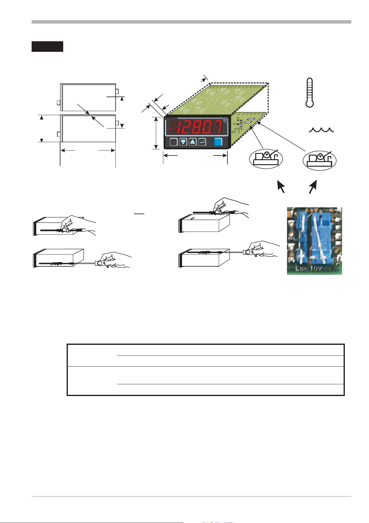
1 Mounting
t
Mounting
+0,6
45
+0.02
10
(0.4")
(4.65")
max.
60°C
0°Cmin.
118
max.
95% rel.
%
10V i mA/P
(1.89")
48
Digital 280-1
OUT1
OUT2
OUT3
ADA
FUNC
ERR
F
min max
96 (3.78")
1..10
(0.04..0.4")
(1.77" )
+0,8
92
+0.03
(3.62" )
min.48
(1.89")
Loc
security switch
or
Ü
Ü
*
a
*
Loc 10V mA/Pt
Safety switch:
For access to the safety switches, the indicator must be withdrawn from the housing. Squeeze the top and bottom of the front bezel between thumb and forefinger
and pull the controller firmly from the housing..
10V i mA/Pt right 1 Current signal / Pt100 / thermocouple/mV at InP
left Voltage signal (V) at InP
Loc open Access to the levels is as adjusted by means of BlueControl
(engineering tool)
2
closed 1 all levels accessible wihout restriction
1 Factory setting 2 Default setting: display of all levels
suppressed, password PASS = OFF
Safety switch 10V i mA/Pt always in position left or right. Leaving the
safety switch open may lead to faulty functions!
l
Digital 280-1 5
Caution! The unit contains ESD-sensitive components.
Page 6
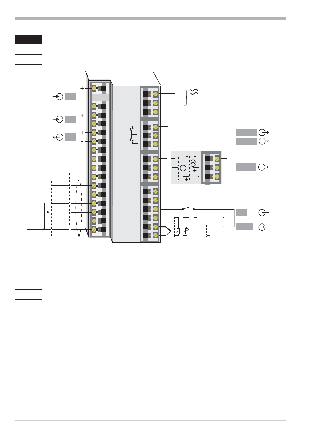
Electrical connections
abcd e
2 Electrical connections
2.1 Connecting diagram
Option
6
6
7
Modbus RTU
RGND
8
DATA B
DATA A
RS485 RS422
RXD-B
GND
RXD-A
TXD-B
TXD-A
di2
di3
U
1
(2)
3
4
5
T
6
7
8
9
10
11
12
13
14
15
16
17
1
2
3
4
5
6
7
8
9
10
11
12
13
14
15
L
N
ghi
Logic
+
U
di1
0
100%
90...250V
24V AC/DC
7
8
9
3
+
mA
mV
+
-
+
4
V*
-
1
OUT1
OUT2
OUT3
5
di1
INP1
2
f
* Safety switch mA i V in position left
g
The indicator is provided with screw terminals from 0,5 to 2,5mm².
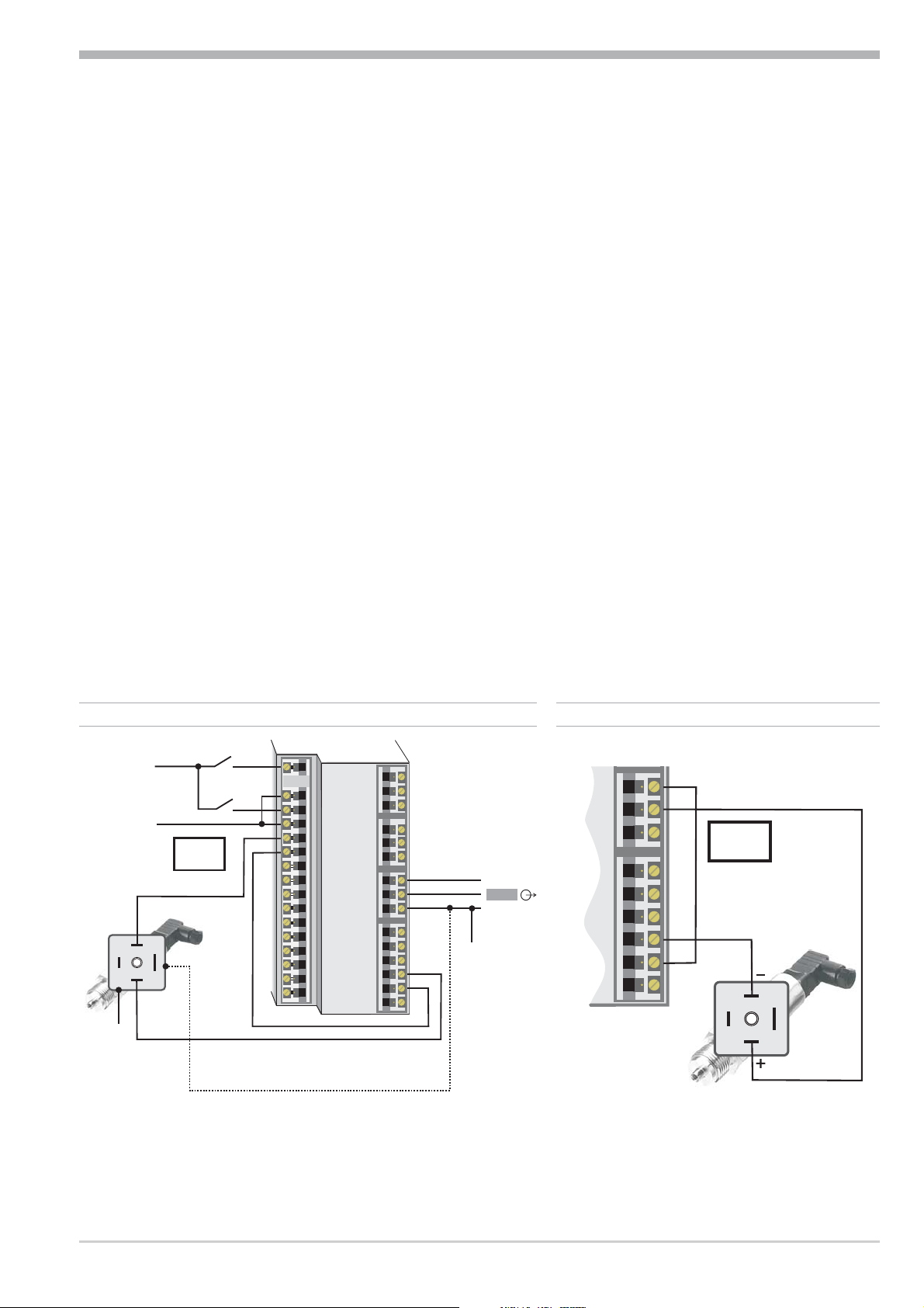
2.2 Terminal connection
Power supply connection 1
See chapter 10 "Technical data"
Connection of input INP1 2
Input for variable x1 (process value)
a thermocouple
b resistance thermometer (Pt100/ Pt1000/ KTY/ ...)
c potentiometer
d current (0/4...20mA)
e voltage (-2,5...115/-25...1150/-25...90/ -500...500mV)
f voltage (0/2...10V/ -5...5V)
6 Connecting diagram Digital 280-1
Page 7
Electrical connections
Connection of input di1 3
Digital input, configurable as switch or push-button
Connection of outputs OUT1/2 4
Relay outputs 250V/2A normally open with common contact connection
Connection of output OUT3 5
g logic (0..20mA / 0..12V)
h voltage (0/2...10V)
i current (0/4...20mA)
i transmitter power supply
Connection of inputs di2/3 6 (option)
Digital inputs (24VDC external), galvanically isolated, configurable as switch or
push-button
Connection of output U
7 (option)
T
Supply voltage connection for external energization
Connection of bus interface 8 (option)
RS422/485 interface with Modbus RTU protocol
67 di2/3, UT2-wire transmitter supply
Option
+24VDC
3
J
0V
17,5V
22mA
+
1
K
2
-
5mA
5mA
1
(2)
3
4
5
+
6
7
-
8
9
10
11
12
13
14
15
16
17
1
5
3
4
5
6
7
8
9
10
11
12
+
13
14
-
15
J
OUT3
6 OUT3 transmitter supply
-
7
8
9
10
11
12
13
14
15
+
13V
22mA
+
-
2
3
K
1
x
a
Digital 280-1 Terminal connection 7
If UTand the universal output OUT3 is used there may be no external galvanic
connection between measuring and output circuits!
Page 8
Electrical connections
+
_
SSR
+
_
SSR
+
_
SSR
+
_
SSR
+
_
SSR
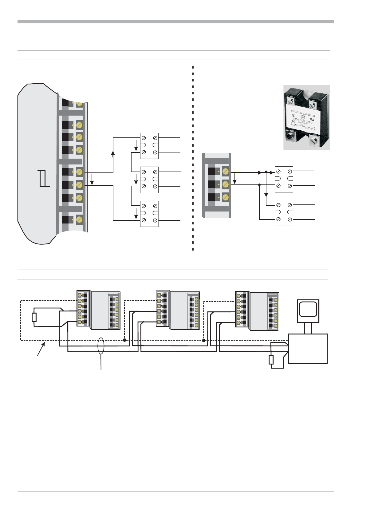
6 OUT 3 als Logikausgang mit Solid-State-Relais (Reihen- und Parallel-Schaltung)
Logic
3
3
4
4
5
5
6
6
7
7
7
8
8
8
9
9
9
10
10
serial installation
I =22mA
max
4V
12V
4V
4V
parallel installation
I =22mA
max
7
7
7
12V
8
8
8
9
9
9
9 RS485 interface (with RS232-RS485 interface converter) *
RT
RGND optional connection
* Interface description Modbus RTU in seperate manual: see page 41.
RGND RGND
DATA B
DATA A
13
13
14
14
15
15
(16)
16
17
17
10
10
11
11
12
12
13
13
14
14
15
15
DATA B
DATA A
12
12
J
12
12
13
13
14
14
15
15
(16)
16
17
17
10
10
11
11
12
12
13
13
14
14
15
15
RGND
DATA B
DATA A
max. 1000m
twisted pair
12
12
13
13
14
14
15
15
(16)
16
17
17
10
10
11
11
12
12
13
13
14
14
15
15
PC
interface
converter
RT
R = line resistanceT
RS485-RS232
8 Terminal connection Digital 280-1
Page 9
+
_
L1
L2
Electrical connections
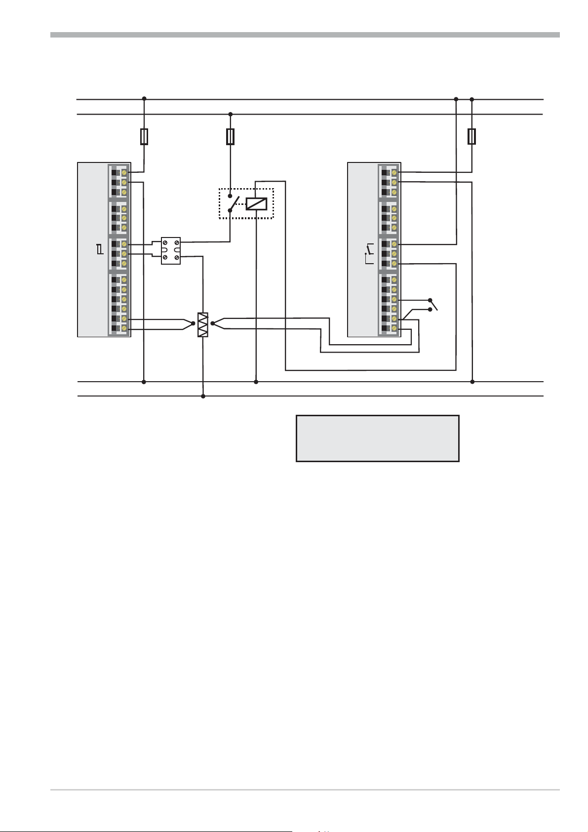
Connecting exampleDigital 280-1:
Digital 280-1
N1
N2
Logic
fuse
fuse
TB 40-1
fuse
1
temperature limiter
1
1
2
2
3
3
4
4
5
5
6
6
7
7
8
8
9
9
10
10
11
11
12
12
13
13
14
14
15
15
SSR
contactor
+
heating
1
1
2
2
3
3
4
4
5
5
6
6
7
7
8
9
10
11
12
13
14
15
resetswitch
+
a
1 TB 40-1 temperature limiter
standard-version (3 relay)
TB40-100-0000D-000
further versions on demandr
CAUTION:
Using a temperature limiter is recommendable in systems where
overtemperature implies a fire hazard or other risks.
Digital 280-1 Terminal connection 9
Page 10
Operation
F
FUNC
ADA
OUT1
OUT2
OUT3
ERR
min max
Digital 280-1
2
3
4
5
6
1
0
987
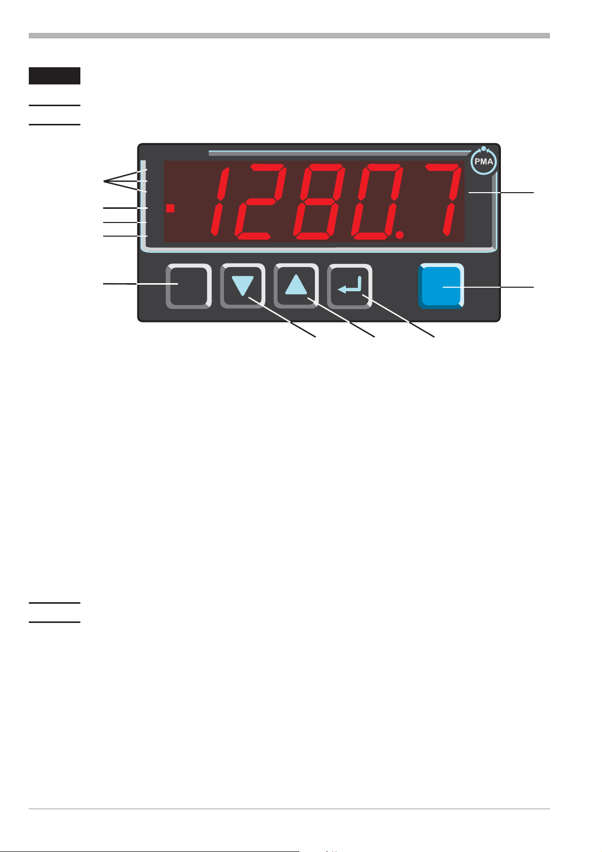
3 Operation
3.1 Front view
1 measured value display
2 statuses of switching outputs OuT.1... 3 (or alarm statuses)
3 lit with self-tuning activated
4 lit with tare or sample & hold function activated
5 lit with entry in the error list
6 function-key
7 down-key
8 up-key
9 enter-key: calls up extended operating level/ errorlist
0 pc connection for BlueControl (engineering-tool)
g
The measured value is displayed as standard. At parameter setting, configuration,
calibration level and at the extended operating level, the display changes
cyclically between parameter name and parameter value.
3.2 Behaviour after power-on
After supply voltage switch-on, the unit starts with the operating level.
The unit is in the condition which was active before power-off.
10 Front view Digital 280-1
Page 11
3.3 Operating level
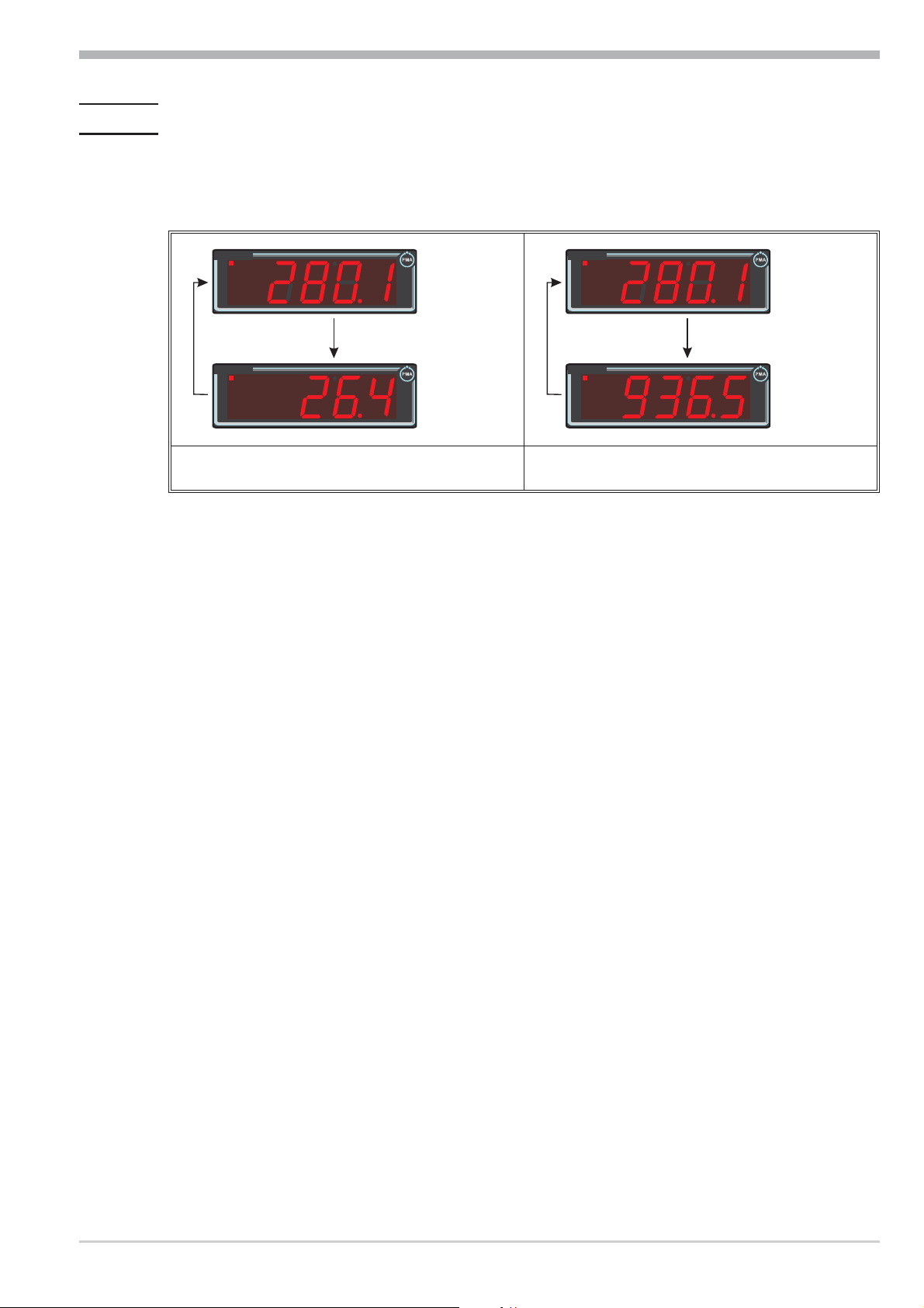
3.3.1 Min/max function
The minimum and maximum values are stored.
Operation
Digital 280-1
OUT1
OUT2
OUT3
ADA
FUNC
ERR
Ì
Digital 280-1
OUT1
OUT2
OUT3
ADA
FUNC
ERR
As long as the Ì key is pressed, the minimum
value is displayed.
min
Digital 280-1
OUT1
OUT2
OUT3
ADA
FUNC
ERR
Ì
Digital 280-1
OUT1
OUT2
OUT3
ADA
FUNC
ERR
As long as the È key is pressed, the maximum
value is displayed.
max
Deleting the minimum value
Keeping the Ì key pressed whilst actuating key È deletes the minimum value.
Additionally, determination whether a digital input or key è should delete the minimum value is possible during configuration (rES.L).
Deleting the minimum and maximum values can be done also via interface.
Deleting the maximum value
Keeping the È key pressed whilst actuating key Ì deletes the maximum value.
Additionally, determination whether a digital input or key è should delete the maximum value is possible during configuration (rES.H).
Deleting the minimum and maximum values can be done also via interface.
g
When switching off Digital 280-1, minimum and maximum values are deleted.
Digital 280-1 Operating level 11
Page 12
3.3.2 Tare function
When switching on the tare function, the instantaneous measured value is set to
zero. In this case, measurement is continued with this offset. By switching off the
tare function, the actual measured value is displayed again.
measured value
effective value
è
ADA
FUNC
ERR
è
è
ADA
ADA
FUNC
FUNC
ERR
ERR
Operation
t
è
ADA
FUNC
ERR
Tare can be activated during configuration (Func r Fnc.1 = 1).
Dependent of configuration, tare can be made effective via one of the digital inputs di1, di2, di3, the
è key or interface (LOGI r tArA).
3.3.3 Sample&hold amplifier
With the sample & hold function activated, the measured value is held on the display. By switching off the sample & hold function, the actual measured value is
displayed again.
measured value
effective value
t
è
è
ADA
FUNC
ERR
è
ADA
FUNC
ERR
è
ADA
FUNC
ERR
è
ADA
ADA
FUNC
FUNC
ERR
ERR
è
ADA
FUNC
ERR
Sample & hold can be activated during configuration (Func r Fnc.1 = 2).
Dependent of configuration, sample & hold can be made effective via one of the
digital inputs di1, di2, di3,the
è -key or via interface (LOGI r HOLd).
Digital 280-1 Operating level 12
Page 13
3.3.4 O2measurement
For measurement, lambda probes (l probes) are used.
The electromotive force (in Volt) supplied by the l probes is dependent of the
instantaneous oxygen content and of the temperature. Therefore, Digital 280-1
can display accurate measurement results only, provided that the probe tempera
ture is known to the indicator.
Enter the temperature in °C in parameter tEmP. When using heated l probes, the
probe temperature can be entered directly. When using non-heated l probes, ho
wever, the displayed values can be accurate only for a narrow temperature band.
Operation
-
-
g
Unless the probe temperature is known, we recommend using our KS90-1
Oxygen (temperature measurement via a second input).
Configuration:
Adjust O
measurement in function 1:
2
Func r Fnc.1 3 O2 measurement
Display: The displayed value is always a % value.
As it is mostly necessary to cover a wide measuring range, we recommend adjusting a high number of digits behind the decimal point during configuration, whereby loss of high values is prevented due to floating decimal point display
(0,0001 (1 ppm) to 99999 is possible) .
Specify the number of digits behind the decimal point below othr :
0 0 digits behind the decimal point
1 1 digit behind the decimal point
othrr dP
2 2 digits behind the decimal point
3 3 digits behind the decimal point
4 4 digits behind the decimal point
Adjust the sensor type to one of the high-impedance voltage inputs in InP:
Specification in BlueControl Effective measuring range
41 Special ( 0...100 mV) -2,5...115 mV
Inp.1r
S.tYP
42 Special ( 0...1000 mV) -25...1150 mV
43 Special ( -25...90 mV)
44 Special ( -500...500 mV)
These high-impedance inputs are not provided with break monitoring. If necessa
ry, measurement input protection is possible via limit value processing.
Digital 280-1 Operating level 13
-
Page 14
Operation
3.3.5 Extended operating level
The content of the extended operating level is determined by means of BlueCon
trol (engineering tool). Parameters which are important or which are used fre
-
quently can be copied into the extended operating level.
Actuating key Ù switches to the first value
Digital 280-1
OUT1
OUT2
OUT3
ADA
FUNC
ERR
of the extended operating level (may be
preceded by error list or set-point).
The selected parameters can be changed
by pressing keys Ì and È.
Ù
Digital 280-1
OUT1
OUT2
OUT3
ADA
FUNC
ERR
Digital 280-1
OUT1
OUT2
OUT3
ADA
FUNC
ERR
Ù
Ù
Digital 280-1
OUT1
OUT2
OUT3
ADA
FUNC
ERR
Press Ù to go to the next parameter.
Digital 280-1
OUT1
OUT2
OUT3
ADA
FUNC
ERR
Press Ù to return to the normal display
after the last parameter .
-
14 Operating level Digital 280-1
Page 15
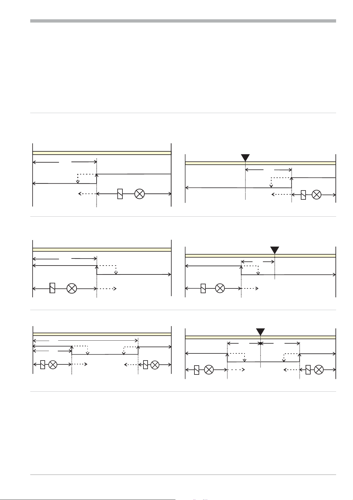
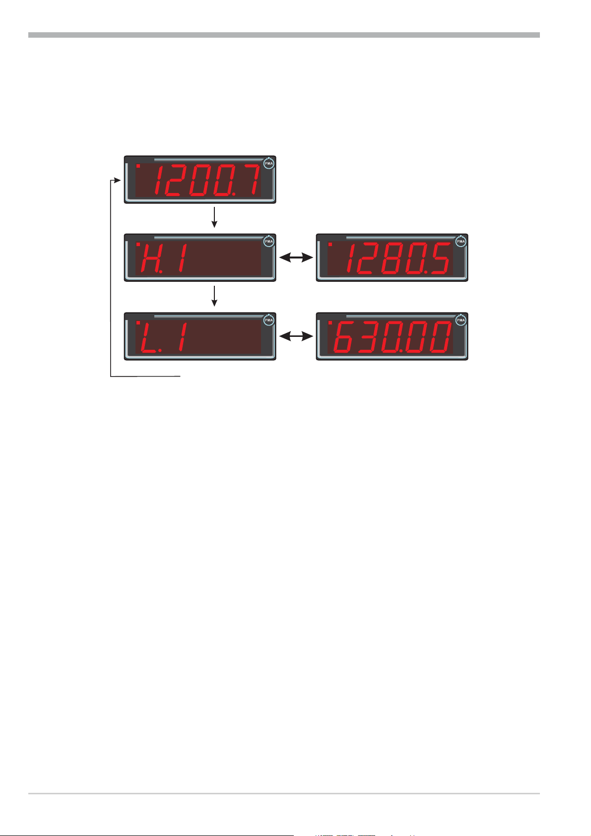
3.3.6 Alarm handling
Operation
Max. three alarms can be configured and assigned to the individual outputs. Ge
nerally, outputs OuT.1... OuT.3 can be used each for alarm signalling. If more
than one signal is linked to one output the signals are OR linked. Each of the 3 li
mit values Lim.1 … Lim.3 has 2 trigger points H.x (Max) and L.x (Min), which
can be switched off individually (parameter = “OFF”). Switching difference
HYS.x of each limit value is adjustable.
Operaing principle absolut alarm
L.1 = OFF
InL.1
H.1
HYS.1
H.1 = OFF
LED
InH.1
Operating principle relative alarm
L.1 = OFFF
SP
InL.1
H.1
HYS.1
H.1 = OFF
-
-
InH.1
LED
InL.1
InL.1
H.1
L.1
L.1
HYS.1
LED
HYS.1 HYS.1
LED
InH.1
InH.1
LED
normally closed ( ConF / Out.x/O.Act = 0 )
normally open ( ConF / Out.x/O.Act = 1 )
InL.1
InL.1
LED
LED
HYS.1
HYS.1
L.1
SP
InH.1
L.1
SP
InH.1
H.1
HYS.1
LED
Digital 280-1 Operating level 15
Page 16

Operation
g
The variable to be monitored can be selected seperately for each alarm via
configuration
The following variables can be monitored:
process value
w
control deviation xw (process value - set-point)
w
control deviation xw + suppression after start-up or set-point change
w
As there is automatically a control deviation after starting up and after
set-point changes, however, the alarm is suppressed, until the signal was
within the limits once.
Set-point
w
Correcting variable y (controller output signal)
w
g
If measured value monitoring + alarm status storage is chosen ( ConF / Lim /
Fnc.x=2), the alarm relay remains switched on until the alarm is resetted in the
error list ( Lim 1..3 = 1) or via interface.
3.4 Maintenance manager / Error list
In case of one or several errors, the extended operating
level always starts with the error list. A current entry
into the error list (alarm or error) is displayed by the
Err LED in the display.
For displaying the error list, pressing 1x Ù is necessary.
(with configuration as a controller, press 2x Ù).
Digital 280-1
OUT1
OUT2
OUT3
ADA
FUNC
ERR
Err LED status Signification Proceed as follows
- Determine the error type in the error list via the error number
- Remove the error
-
Acknowledge the alarm in the error list pressing key È or Ì
-
The alarm entry was deleted.
g
blinks Alarm due to
existing error
lit Error removed,
Alarm not
acknowledged
off No error, all alarm entries deleted
Saved alarms (Err-LED is lit) can be acknowledged and deleted with the digital
input di1/2/3 or the Ò-key.
Configuration, see page 31: ConF / LOGI / Err.r
g
If an alarm is still valid that means the cause of the alarm is not removed so far
(Err-LED blinks), then other saved alarms can not be acknowledged and deleted.
Error status Signification
2 Existing error Change to error status 1 after error removal
1 Stored error Change to error status 0 after acknowledgement in error list
0 No error/message not visible, except with acknowledgement
16 Maintenance manager / Error list Digital 280-1
Page 17

Controller
4 Controller
In addition to the simple indicator function, Digital 280-1 can be used also as a
signaller or an on/off controller, as a two point or a continuous controller.
Prerequisite: Digital 280-1 is fitted with option “with outputs” and is configured
for the controller function.
Configuration:
Function 2 provides selection between indicator and controller:
4.1 Operation
Adjusting the set-point
Digital 280-1
OUT1
OUT2
OUT3
ADA
FUNC
ERR
Digital 280-1
OUT1
OUT2
OUT3
ADA
FUNC
ERR
error list, if errors pending
Func r Fnc.2
Ù
Ù
Ù
Controller
Press key Ù to switch over to the
set-point. The set-point can be changed
by pressing keys Ì und È .
Digital 280-1
OUT1
OUT2
OUT3
ADA
FUNC
ERR
extended operating level, if configured
Ù
4.2 Control parameters
The range of different processes to be controlled is very wide, from very fast
pressure control to very slow thermal processes such as control of a blast furnace.
As the controller behaviour has to be different with each of these processes, the
control parameters must be adjusted for the relevant process individually. Adjust
ment can be done either manually or by the controller itself.
Digital 280-1 Operation 17
-
Page 18

Controller
4.3 Self-tuning
After starting by the operator, the controller makes a self-tuning attempt. The
controller uses the process characteristics for quick line-out to the set-point wit
hout overshoot.
-
g
g
Self-tuning start can be locked via BlueControl (engineering tool) ( P.Loc).
ti and td are taken into account only, if they were ¹ OFF previously.
4.3.1 Self-tuning start ( Ù + È )
The operator can start self-tuning at any time. For
this, keys Ù and È must be pressed simultane
ously. The AdA LED starts blinking.
The controller outputs 0% or Y.Lo, waits until the
process is at rest and starts self-tuning (AdA LED
lit permanently).
The self-tuning attempt is started when the following prerequisite is met:
The difference between process value i set-point must be ³ 10% of the
w
set-point range ( SP.Hi - SP.LO) (with inverse action: process value smaller
than set-point, with direct action: process value higher than set-point).
After successful self-tuning, the AdA-LED is off and the controller continues
operating with the new control parameters.
Digital 280-1
OUT1
-
OUT2
OUT3
ADA
FUNC
ERR
4.3.2 Self-tuning cancellation
By the operator:
Self-tuning can always be cancelled by the operator. For this, press Ù and È
key simultaneously. The controller continues operating with the old parameters.
By the controller:
If the Err LED starts blinking whilst self-tuning is running, successful self-tuning
is prevented due to the control conditions. In this case, self-tuning was cancelled
by the controller.
Dependent of control type, the output status is:
3-pnt. stepping controller:
w
actuator is closed (0% output)
2-pnt./ 3-pnt./ continuous controller:
w
If self-tuning was started from the automatic mode, the controller output is
0%. With self-tuning started from manual mode, the controller output is Y2.
18 Self-tuning Digital 280-1
Page 19

Controller
blinks
lit off
Error-Status Selfoptimization
Error status Description Behaviour
0 No error
3 Faulty control action Re-configure controller (inverse i direct)
4 No response of process variable The control loop is perhaps not closed: check
sensor, connections and process
5 Low reversal point Increase ( ADA.H) max. output limiting Y.Hi or
decrease ( ADA.C) min. output limiting Y.Lo
6 Danger of exceeded set-point
(parameter determined)
7 Output step change too small
(dy > 5%)
8 Set-point reserve too small Increase set-point (inverse), reduce set-point
If necessary, increase (inverse) or reduce (direct)
set-point
Increase ( ADA.H) max. output limiting Y.Hi or
reduce ( ADA.C) min. output limiting Y.Lo
(direct) or increase set-point range(r PArA / SEtp
/ SP.LO and SP.Hi )
4.3.3
Acknowledgement procedures in case of unsuccessful self-tuning
1. Press keys Ù and È simultaneously:
The controller continues controlling using the old parameters
The Err LED continues blinking, until the self-tuning error was
acknowledged in the error list.
2. Press key Ù :
Display of error list at extended operating level. After acknowledgement
of the error message, the controller continues control using the old
parameters.
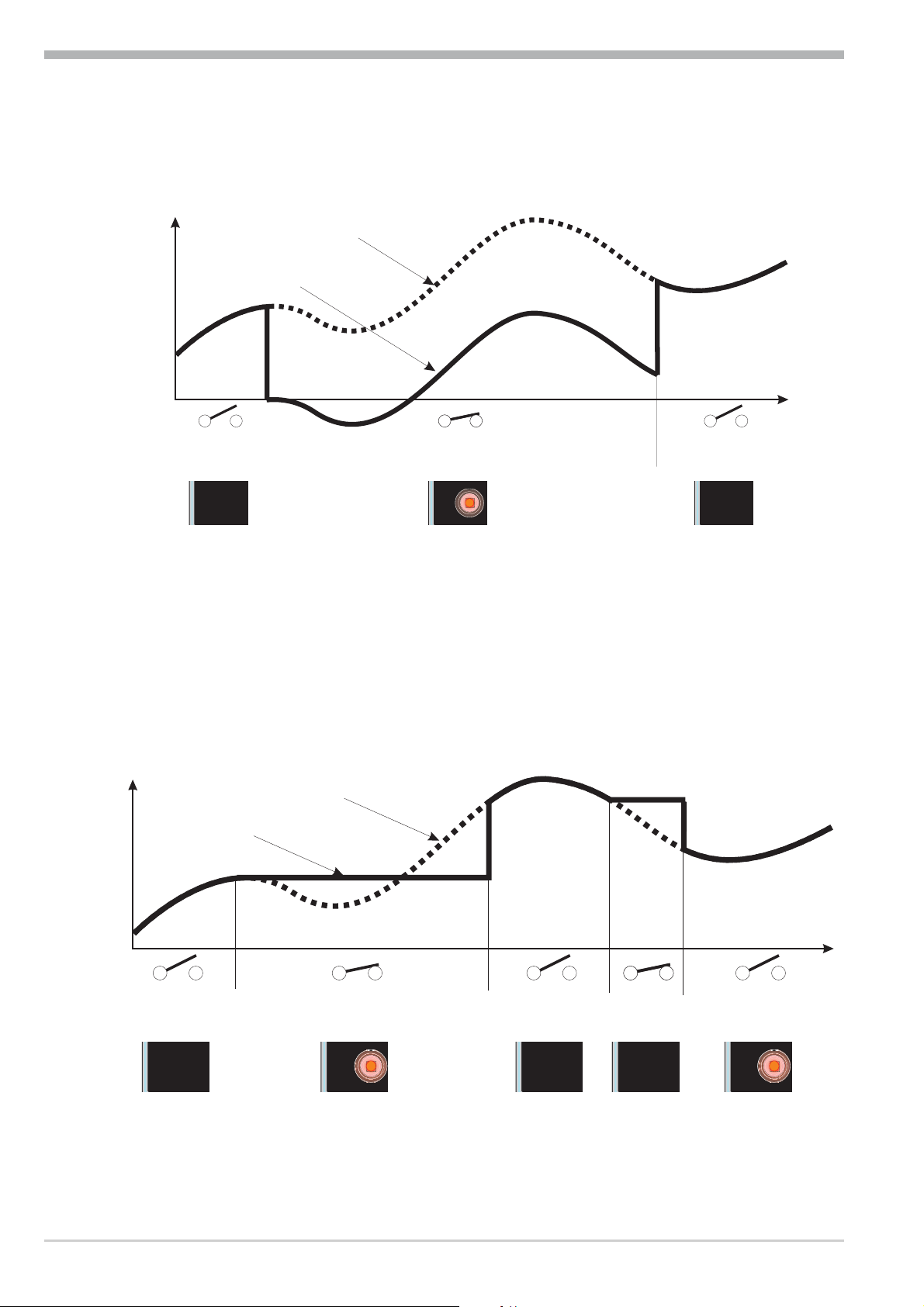
4.3.4 Examples for self-tuning attempts
4.3.5 (controller inverse, heating or heating/cooling)
X
Start: heating power switched on
W
Heating power Y is switched off (1).
When the change of process value X
was constant during one minute (2),
the power is switched on (3).
At the reversal point, the self-tuning at
100%
Y
0%
-
start r
tempt is finished and the new parameter
are used for controlling to set-point W.
1
2
3
t
t turning point
Digital 280-1 Self-tuning 19
Page 20

Controller
blinks lit
off
y
blinks lit off
Start: heating power switched off
The controller waits 1,5 minutes (1).
Heating power Y is switched on (2).
At the reversal point, the self-tuning at
tempt is finished and control to the
set-point is using the new parameters.
Start: at set-point
Heating power Y is switched off (1).
If the change of process value X was
constant during one minute and the con
trol deviation is > 10% of SP.Hi SP.LO (2), the power is switched on
(3). At the reversal point, the self-tu
ning attempt is finished, and control to
set-point W is using the
new parameters.
X
W
-
100%
0%
X
W
Y
start r
1
2
2
t turning point
t
-
100%
0%
Y
start r
1
3
t turning point
t
4.4 Manual tuning
The optimization aid should be used with units on which the control parameters
shall be set without self-tuning.
For this, the response of process variable x after a step change of correcting variable y can be used. Frequently, plotting the complete response curve (0 to
100%) is not possible, because the process must be kept within defined limits.
Values T
sponse) can be used to determine the maximum rate of increase v
100%
Y
h
0%
x
X
max
and x
g
(step change from 0 to 100 %) or Dt and Dx (partial step re-
max
.
max
y = correcting variable
Y
= control range
h
Tu = delay time (s)
t
Tg
{X
{t
Tg = recovery time (s)
X
V
= maximum process value
max
{{x
=
t
max
Xmax
=
Tg
= max. rate of
increase of process value
Tu
t
Digital 280-1 Manual tuning 20
Page 21

Controller
The control parameters can be determined from the values calculated for delay
time T
, maximum rate of increase v
u
, control range Xhand characteristic K ac
max
cording to the formulas given below. Increase Xp, if line-out to the set-point os
cillates.
Parameter adjustment effects
Parameter Control Line-out of disturbances Start-up behaviour
Pb1 higher increased damping slower line-out slower reduction of duty cycle
lower reduced damping faster line-out faster reduction of duty cycle
td1 higher reduced damping faster response to disturbances faster reduction of duty cycle
lower increased damping slower response to disturbances slower reduction of duty cycle
ti1 higher increased damping slower line-out slower reduction of duty cycle
lower reduced damping faster line-out faster reduction of duty cycle
-
-
Formulas
K = Vmax * Tu controller behavior Pb1 [phy. units] td1 [s] ti1 [s]
PID 1,7*K 2*Tu 2*Tu
With 2-point and
3-point controllers,
the cycle time must
be adjusted to
t1 / t2 £ 0,25 * Tu
PD 0,5 * K Tu OFF
PI 2,6 * K OFF 6 * Tu
P K OFF OFF
3-point-stepping 1,7 * K Tu 2 * Tu
Digital 280-1 Manual tuning 21
Page 22

4.5 Operating structure
After supply voltage switch-on, the controller starts with the operating levels.
Controller
g
g
Digital 280-1
OUT1
OUT2
OUT3
ADA
FUNC
ERR
3s
Ù
Digital 280-1
OUT1
OUT2
OUT3
ADA
FUNC
ERR
Ì
Digital 280-1
OUT1
OUT2
OUT3
ADA
FUNC
ERR
Ì
Digital 280-1
OUT1
OUT2
OUT3
ADA
FUNC
ERR
Ì
Digital 280-1
OUT1
OUT2
OUT3
ADA
FUNC
ERR
Ù
PASS
Ù
PASS
Ù
PArA - level:
At PArA - level, the right decimal point of the upper display line is lit
continuously.
ConF - level:
At ConF - level, the right decimal point of the upper display line blinks
When safety switch Loc is open, only the levels enabled by means
of BlueControl (engineering tool) are visible and accessible by entry
PASS
of the password adjusted by means of BlueControl (engineering
tool). Individual parameters accessible without password must be
copied to the extended operating level.
PASS
Ù
Factory setting:
Safety switch Loc closed: all levels accessible without
restriction, password PASS = OFF.
Safety switch
Loc
closed OFF / password disabled / enabled
open OFF / password disabled
open OFF enabled
open Password enabled
Password entered with
BluePort®
Function disabled or enabled
with BluePort®
Access via the instrument
front panel:
enabled
disabled
enabled
enabled after password
entry
Digital 280-1 Operating structure 22
Page 23

5 Configuration level
5.1 Configuration survey
ConF Configuration level
Func
Functions
InP
Input
Lim
Limits
È
Fnc.1 StYP Fnc.1 O.Act
Ì
Fnc.2 S.Lin Src.1 Y.1 O.Act Err.r Addr
C.Fnc Corr Fnc.2 Lim.1 Y.1 tArA PrtY
C.Act Src.2 Lim.2 Lim.1 HOLd dELY
rnG.L Fnc.3 Lim.3 Lim.2 rES.L Unit
rnG.H Src.3 FAi.1 Lim.3 rES.H dP
OUt.1
Output 1
OUt.2
Output 2
OUt.3
Output 3
LOGI
O.tYP L_r bAud
FAi.1 di.Fn DISP
See output 1
OuT.0 C.dEl
Out.1
O.Src
digital Inputs
Othr
Display, operation,
Configuration level
interface
End
g
Adjustment:
The configuratiuons can be adjusted by means of keys ÈÌ .
w
Transition to the next configuration is by pressing key Ù .
w
After the last configuration of a group, donE is displayed and followed by
w
automatic change to the next group
Return to the beginning of a group by pressing the Ù key for 3 sec.
Digital 280-1 Configuration survey 23
Page 24

5.2 Configuration
Configuration level
Dependent of instrument version and configuration, spare parameters are not dis
played.
Func
name value range description default
Fnc.1
Fnc.2
C.Fnc
C.Act
rnG.L
rnG.H
0
1
2
3
0
1
0
1
0
1
-19999...99999
-19999...99999
function 1
no function
tare - function
sample & hold
O2 - measuring
function 2
indicator
controller
controller behavior (algorithm)
on/off controller e.g. signaller with one output
PID-controller (2-point and continuous)
operating principle of the controller
inverse, e.g. heating
direct, e.g. cooling
X0 (lower controlrange limit) 1
X100 (upper controlrange limit) 1
0
0
1
0
-100
1200
-
1 rnG.L and rnG.H indicate the control range to which self-tuning refers.
InP
name value range description default
S.tYP
sensortype
0
1
2
3
4
5
6
7
8
9
thermocouple type L (-100...900°C), Fe-CuNi DIN
thermocouple type J (-100...1200°C), Fe-CuNi
thermocouple type K (-100...1350°C), NiCr-Ni
thermocouple type N (-100...1300°C), Nicrosil-Nisil
thermocouple type S (0...1760°C), PtRh-Pt10%
thermocouple type R (0...1760°C), PtRh-Pt13%
thermocouple type T (-200...400°C), Cu-CuNi
thermocouple type C (0...2315°C), W5%Re-W26%Re
thermocouple type D (0...2315°C), W3%Re-W25%Re
thermocouple type E (-100...1000°C), NiCr-CuNi
10 thermocouple type B (0/100...1820°C), PtRh-Pt6%
18
20
21
22
23
24
30
40
thermocouple Sonder (linearization necessary)
pt100 (-200.0 ... 100,0 °C)
pt100 (-200.0 ... 850,0 °C)
pt1000 (-200.0...8500.0 °C)
special 0...4500 Ohm (preset to KTY11-6)
special 0...450 Ohm (scaling necessary)
0...20mA / 4...20 mA (scaling necessary r page 36)
0...10V / 2...10 V (scaling necessary r page36)
1
Digital 280-1 Configuration 24
Page 25

Configuration level
name value range description default
S.Lin
Corr
fAI1
41
42
43
44
45
50
51
52
special (-2,5...115 mV scaling necessary r page36)
special (-25...1150 mV scaling necessary r page 36)
special (-25...90 mV scaling necessary r page 36)
special (-500...500 mV scaling necessary r page 36)
special (-5...5 V scaling necessary r page 36)
potentiometer 0...160 Ohm
potentiometer 0...450 Ohm
potentiometer 0...1600 Ohm
linearization only adjustable with S.tYP: 18, 23, 24, 30, 40 ... 45
0
1
none
Special linearization
0
Editing the linearization table with BlueControl (engineering tool) is
possible. The characteristic for KTY 11-6 temperature sensors is factory-set.
measurement value correction / scaling
0
1
2
3
no correction
offset-correction (in CAL - level)
2-point-correction (in CAL - level)
scaling (in PArA - level)
forcing INP (only visible with BlueControl!)
0
1
no forcing
forcing via interface
0
0
Lim
name value range description default
Fnc.1
Fnc.2
Fnc.3
Src.1
Src.2
Src.3
Hour
Swit
0
1
2
3
4
0
1
2
3
6
7
OFF..999999
OFF..999999
function of limit 1 (2, 3)
switched off
measured value monitoring
measured value monitoring + storing of alarm status.
A stored limit value can be set back via error list or digital input or
è -key (® LOGI/ Err.r).
signal change
signal change + storing of alarm status.
A stored limit value can be set back via error list or digital input or
è -key (® LOGI/ Err.r).
source for limit value 1 (2, 3)
process value = absolut alarm
control deviation Xw (processvalue - set-point) = relative alarm
control deviation Xw (=relative alarm) with suppression at start
and with set-point change
measured value INP
set-point
y (controller output)
operating hours (only visible with BlueControl!)
operation cycle number (only visible with BlueControl!)
1
0
OFF
OFF
25 Configuration Digital 280-1
Page 26

Configuration level
Out.1 und Out.2
name value range description default
O.Act
Y.1
Lim.1
Lim.2
Lim.3
FAi.1
fOut
circuit direction of output OUT1
0
1
direct / open circuit principle
inverse / closed circuit priciple
controller output Y1
0
1
not active
active
0
0
message limit value 1/2/3
0
1
0
1
0
1
not active
active
message INP error
not active
active
forcing OUT1 (2) (only visible with BlueControl!)
no forcing
forcing via interface
Out. 1/2/3
0
0
Out.3
name value range description default
O.tYP
O.Act
Y.1
Lim.1
Lim.2
Lim.3
FAi.1
Out.0
Out.1
0
1
2
3
4
5
0
1
0
1
0
1
0
1
0
1
-19999...
99999
-19999...
99999
signaltype OUT3
relay / logic
0 ... 20 mA continuous
4 ... 20 mA continuous
0...10V continuous
2...10V continuous
transmitter supply
circuit direction of output OUT3 (only visible with O.TYP=0 )
direct / open circuit principle
inverse / closed circuit priciple
controller output Y1 (only visible with O.TYP=0)
not active
active
message limit value 1 (only visible with O.TYP=0)
not active
active
message limit value 2/3 (only visible with O.TYP=0)
not active
active
message INP-error (only visible with O.TYP=0)
not active
active
scaling of analog output for 0% (0/4mA e.g. 0/2V, only visible
with O.TYP=1..5)
scaling of analog output for 100% (20mA bzw. 10V, only
visible with O.TYP=1..5)
0
1
0
1
0
1
0
100
26 Configuration Digital 280-1
Page 27

Configuration level
name value range description default
O.Src
fOut
signalsource for analog output OUT3 (only visible with O.TYP=1..5)
0
1
3
4
5
not active
controller output y1 (continuous)
process value
effective set-point Weff
control deviation xw (process value - set-point )
forcing OUT3 (only visible with BlueControl!)
0
1
no forcing
forcing via interface
1
0
LOGI
name value range description default
L_r
Err.r
tArA
HoLd
rES.L
local / remote swith-over (remote: adjustment of all values via
front is blocked)
0
1
2
3
4
5
no function (switch-over via interface is possible)
always active
di1 switches
di2 switches(only visible with OPTION)
di3 switches(only visible with OPTION)
è -key switches
reset of all stored messages of the errorlist
0
2
3
4
5
0
2
3
4
5
0
2
3
4
5
0
2
3
4
5
no function (switch-over via interface is possible)
di1 switches
di2 switches (only visible with OPTION)
di3 switches (only visible with OPTION)
è -key switches
no function (switch-over via interface is possible)
di1 switches
di2 switches (only visible with OPTION)
di3 switches (only visible with OPTION)
è -key switches
no function (switch-over via interface is possible)
di1 switches
di2 switches (only visible with OPTION)
di3 switches (only visible with OPTION)
è -key switches
no function (switch-over via interface is possible)
di1 switches
di2 switches (only visible with OPTION)
di3 switches (only visible with OPTION)
è -key switches
0
0
0
0
0
Digital 280-1 Configuration 27
Page 28

Configuration level
name value range description default
rES.H
di.Fn
fDI1
fDI2
fDI3
othr
0
0
2
3
4
5
0
1
2
no function (switch-over via interface is possible)
di1 switches
di2 switches (only visible with OPTION)
di3 switches (only visible with OPTION)
è -key switches
function of digital inputs (valid for all inputs)
direct
inverse
keyfunction (adjustable for 2-point-operation with interface and
0
di1/2/3 or front-key)
forcing di1/di2/di3 (only visible with BlueControl!)
0
1
no forcing
forcing via interface
0
name value range description default
bAud
Addr
PrtY
dELY
Unit
dP
dIsp
0
1
2
3
1...247
0
1
2
3
0...200
0
1
2
0
1
2
3
4
1
2
3
4
5
6
7
baudrate of interface (only visible with OPTION)
2400 baud
4800 baud
9600 baud
19200 baud
adresse of Schnittstelle (only visible with OPTION)
parity of data on interface (only visible with OPTION)
no parity (2 stopbits)
even parity
odd parity
no parity with 1 stopbit
response delay [ms] (only visible with OPTION)
unit
no unit
°C
°F
dezimalpoint (max. dezimalpoint )
no decimalplace
1 decimalplace
2 decimalplaces
3 decimalplaces
4 decimalplaces
measuring value display
full display resolution
display resolution= 2 digits
display resolution= 5 digits
display resolution= 10 digits
display resolution= 20 digits
display resolution= 50 digits
display resolution= 100 digits
2
1
1
0
1
0
1
28 Configuration Digital 280-1
Page 29

Configuration level
name value range description default
C.dEl
FrEq
IAdA
IExo
ILat
Pass
IPar
ICnf
ICal
0..200
0
1
0
1
0
1
0
1
OFF...99999
0
1
0
1
0
1
modem delay [ms]
switch-over 50/60 Hz (only visible with BlueControl!)
netfrequency 50 Hz
netfrequency 60 Hz
blocked selfoptimization (only visible with BlueControl!)
free
blocked
extended operation level blocked (only visible with BlueControl!)
free
blocked
suppression error memory
free
blocked
password -19999 ...99999
parameterlevel blocked (only visible with BlueControl!)
free
blocked
configurationlevel blocked (only visible with BlueControl!)
free
blocked
calibrationlevel blocked (only visible with BlueControl!)
free
blocked
0
0
0
0
OFF
1
1
1
g
+
Resetting the controller configuration to factory setting (Default)
r chapter 11.1 (page 47)
BlueControl - the engineering tool for the BluePortâcontroller series
Three engineering tools with different functionality facilitating Dig 280-1 confi
guration and parameter setting are available (see chapter 8 : Accessory equipment
with ordering information). In addition to configuration and parameter setting,
the engineering tools are used for data acquisition and offer long-term storage
and print functions. The engineering tools are connected to Dig 280-1 via the
front-panel interface "BluePort
â
" by means of PC (Windows 95 / 98 / NT) and a
PC adaptor.
Description BlueControl: see chapter 8: BlueControl (page 40)
-
Digital 280-1 Configuration 29
Page 30

Configuration level
5.3 Configuration examples
5.3.1 On-Off controller / Signaller (inverse)
SP.LO SP
SP.Hi
InH.1InL.1
InP.1Ê
100%
Out.1Â
0%
ConF / Cntr: SP.Fn = 0 set-point controller
C.Fnc = 0 signaller with one output
C.Act = 0 inverse action
ConF / Out.1: O.Act = 0 action Out.1 direct
Y.1 = 1 control output Y1 active
PArA / Cntr: SH = 0...9999 switching difference (symmetrical
PArA / SEtP: SP.LO = -1999...9999 set-point limit low for Weff
SP.Hi = -1999...9999 set-point limit high for Weff
For direct signaller action, the controller action must be changed
(ConF / Cntr / C.Act = 1 )
SH
(e.g. heating applications)
to the trigger point)
process-value
SH
Set-point
Output
30 Configuration examples Digital 280-1
Page 31

5.3.2 2-point controller (inverse)
Configuration level
SP.LO SP
SP.Hi
InH.1InL.1
InP.1Ê
100%
PB1
Out.1Â
0%
ConF / Cntr: SP.Fn=0 set-point controller
C.Fnc = 1 2-point controller (PID)
C.Act = 0 inverse action
(e.g. heating applications)
ConF / Out.1: O.Act = 0 action Out.1 direct
Y.1 = 1 control output Y1 active
PArA / Cntr: Pb1 = 0,1...9999 proportional band 1 (heating)
in units of phys. quantity (e.g. °C)
ti1 = 1...9999 integral time 1 (heating) in sec.
td1 = 1...9999 derivative time 1 (heating) in sec.
t1 = 0,4...9999 min. cycle time 1 (heating)
PArA / SEtP: SP.LO = -1999...9999 set-point limit low for Weff
SP.Hi = -1999...9999 set-point limit high for Weff
g
For direct action, the controller action must be changed
(ConF / Cntr / C.Act = 1 ).
Set-point
Process-value
Output
Digital 280-1 Configuration examples 31
Page 32

Configuration level
5.3.3 Continuous controller (inverse)
SP.LO SP
SP.Hi
InH.1InL.1
InP.1Ê
20 mA
PB1
Out.3Â
0/4 mA
ConF / Cntr: SP.Fn=0 set-point controller
C.Fnc = 1 continuous controller (PID)
C.Act = 0 inverse action
(e.g. heating applications)
ConF / Out.3: O.tYP = 1 / 2 Out.3 type ( 0/4 … 20mA )
Out.0 = -1999...9999 scaling analog output 0/4mA
Out.1 = -1999...9999 scaling analog output 20mA
PArA / Cntr: Pb1 = 0,1...9999 proportional band 1 (heating)
in units of phys. quantity (e.g. °C)
ti1 = 1...9999 integral time 1 (heating) in sec.
td1 = 1...9999 derivative time 1 (heating) in sec.
t1 = 0,4...9999 min. cycle time 1 (heating)
PArA / SEtP: SP.LO = -1999...9999 set-point limit low for Weff
SP.Hi = -1999...9999 set-point limit high for Weff
g
g
For direct action of the continuous controller, the controller action must be
changed ( ConF / Cntr / C.Act = 1 ).
To prevent control outputs Out.1 and Out.2 of the continuous controller from
switching simultaneously, the control function of outputs Out.1 and Out.2
must be switched off ( ConF / Out.1 and Out.2 / Y.1 and Y.2 = 0 ).
32 Configuration examples Digital 280-1
Page 33

5.3.4 Digital 280-1 with measured value output
phys.
unit
Out.1
Configuration level
phys. unit
Logic
U
Out.0
0/4mA
0/2V
7
8
9
20mA
10V
OUT3
mA / V
ConF / Out.3: O.tYP = 1 Out.3 0...20mA continuous
= 2 Out.3 4...20mA continuous
= 3 Out.3 0...10V continuous
= 4 Out.3 2...10V continuous
Out.0 = -1999...9999 scaling Out.3
for 0/4mA or 0/2V
Out.1 = -1999...9999 scaling Out.3
for 20mA or 10V
O.Src=3 signal source for Out.3 is
the process value
Digital 280-1 Configuration examples 33
Page 34

Parameter setting level
6 Parameter setting level
6.1 Parameter survey
Depending on unit version and configuration spare parameters are not shown.
PArA Parameter-Level
È
Ì
Func Functions
tEmP InL L.1
Pb1 OuL H.1
ti1 InH HYS.1
td1 OuH dEL.1
t1 tF L2
SH
Y2
Y.Lo dEL.2
Y.Hi L.3H.3
Y0 HYS.3
SP.LO HYS.3
SP.Hi dEL.3
b.F
E.tc
InP Input
H.2
HYS.2
Lim Limits
End
Adjustment:
The parameters can be adjusted by means of keys ÈÌ
w
Transition to the next parameter is by pressing key Ù
w
After the last parameter of a group, donE is displayed, followed by
w
automatic change to the next group.
g
Return to the beginning of a group is by pressing the Ù key for 3 sec.
If for 30 sec. no keypress is excecuted the controler returns to the process va
lue and setpoint display ( Time Out = 30 sec. )
Digital 280-1 Parameter survey 34
-
Page 35

Parameter setting level
6.2 Parameter
Func
name value range description default
tEmP
Pb1
ti1
td1
t1
SH
Y2
Y.Lo
Y.Hi
Y.0
Sp.LO
SP.Hi
1...99999 1
1...99999 1
1...99999
1...99999
0,4...99999
0...9999
-120...120
-120...120
-120...120
-120...120
-99999...99999
-99999...99999
probetemperature for O2measuring
proportional band in phys. unit (z.B. °C)
reset time 1 [s] (ti1=0= off = switched off)
derivative time1 (heating) [s] (td1=0= off = switched off)
min. cycle duration1 (heating) [s].
The smallest pulse duration is 1/4 x t1
neutral zone, e.g. switching difference signalunit [phys. unit]
2nd control value [%] becomes effective with recognized process
value error -FAIL
lower controller value limit [%]
upper controller value limit [%]
working point for controller value [%]
lower set-point limit [phys. unit]
upper set-point limit [phys. unit]
650
100
180
180
10
2
0
0
100
0
0
100
1 Valid for ConF/ othr/ DP = 0.At DP = 1/ 2/ 3/4 so 0,1 / 0,01 / 0,001, 0,0001.
InP
name value range description default
InL
OuL
InH
OuH
t.F
b.F
E.tc
-19999...99999
-19999...99999
-19999...99999
-19999...99999
0,1...999,9
0...99999
0...100
input value of lower scaling point
display value of lower scaling point
input value of upper scaling point
display value of upper scaling point
filtertime constant [s]
filterbandwidth
external temperaturecompensation
0
0
20
20
0,5
5
OFF
Lim
name value range description default
L.1
H.1
HYS.1
dEL.1
L.2
H.2
HYS.2
dEL.2
L.3
H.3
HYS.3
dEL.3
-19999...99999
-19999...99999
0...99999
0...99999
-19999...99999
-19999...99999
0...99999
0...99999
-19999...99999
-19999...99999
0...99999
0...99999
lower limit value 1 (L.1< -19999 = off)
upper limit value 1 (H.1< -19999 = off)
hysteresis of limit value 1
alarm 1 delay
lower limit value 2 (L.2< -19999 = off)
upper limit value 2 (H.2< -19999 = off)
hysteresis of limit value 2
alarm 2 delay
lower limit value 3 (L.3< -19999 = off)
upper limit value 3 (H.3< -19999 = off)
hysteresis of limit value 3
alarm 3 delay
-10
10
1
0
OFF
OFF
1
0
OFF
OFF
1
0
g
Resetting the controller configuration to factory setting (Default)
r chapter 11.1 (page 47)
Digital 280-1 Parameter 35
Page 36

Parameter setting level
6.3 Input scaling
When using current or voltage signals as input variables for InP.1 or InP.2,
scaling of input and display values at parameter setting level is required. Specifi
cation of the input value for lower and higher scaling point is in the relevant elec
trical unit (mA / V).
phys.
unit
OuH.x
-
-
mA / V
6.3.1 Input Inp
g
Parameters InL.1 , OuL.1, InH.1 and OuH.1 are only visible if
ConF / InP.1 / Corr = 3 is chosen.
The parameters InL and InH determine the input range
Example mA:
InL= 4 and InH 0 20 means, the measurement is from 4 to 20 mA.
a
For using the predetermined scaling with thermocouple and resistance
thermometer (Pt100), the settings for InL.1 and OuL.1 and for InH.1 and
OuH.1 must have the same value.
OuL.x
InL.x
InH.x
phys. unit
mA/V
36 Input scaling Digital 280-1
Page 37

7 Calibration level
Calibration level
g
Measured value correction ( CAL) is only visible if ConF / InP.1 / Corr = 1
or 2 is chosen.
The measured value can be matched in the calibration menu ( CAL). Two me
thods are available:
7.1 Offset correction
( ConF/ InP.1 / Corr =1 ):
possible on-line at the process
display
OuL
OuLold
-
standard-setting
Offset-correction
new
2-point correction
( ConF/ InP.1 / Corr = 2 ):
is possible off-line with process
w
value simulator
online in 2 Schritten zunächst
w
den einen Wert korrigieren und
später, z.B. nach dem Aufheizen
des Ofens, den zweiten Wert
korrigieren.
Display
OuH
OuH
OuLneu
OuLalt
alt
neu
InL
InL
Standardeinstellung
2-Punkt-Korrektur
InH
X
X
Digital 280-1 Offset correction 37
Page 38

Calibration level
Offset correction ( ConF/ InP.1 / Corr =1 ):
Digital 280-1
OUT1
OUT2
OUT3
ADA
FUNC
ERR
r
Ù
3sec.
r
PArA
r
Ì
ConF
r
Ì
CAL
r
Ù
r
InP
r
Ù
r
r
InL
È
InL
Ù
OuL
r
È
Ì
Ù
Ù
InL.1: The input value of the scaling point is displayed.
The operator must wait, until the process is at rest.
Subsequently, the operator acknowledges the input value by pressing
key Ù.
OuL.1: The display value of the scaling point is displayed.
Before calibration, OuL.1 is equal to InL.1.
The operator can correct the display value by pressing keys ÈÌ .
Subsequently, he confirms the display value by pressing key Ù.
r
End
r
Ù
38 Offset correction Digital 280-1
Page 39

2-point correction ( ConF/ InP.1 / Corr =1 ):
Digital 280-1
OUT1
OUT2
OUT3
ADA
FUNC
ERR
r
Ù
3sec.
r
PArA
r
Ì
ConF
r
Ì
CAL
r
Ù
r
InP
rr
Ù
InL
È
InL
Ù
OuL
InH
È
InH
Ù
OuH
Calibration level
r
Ù
È
r
Ù
Ì
r
Ù
È
r
Ù
Ì
r
End
r
InL.1: The input value of the lower scaling point is displayed.
The operator must adjust the lower input value by means of a
process value simulator and confirm the input value by pressing key Ù.
OuL.1: The display value of the lower scaling point is displayed.
Before calibration, OuL.1 equals InL.1.
The operator can correct the lower display value by pressing the ÈÌ
keys. Subsequently, he confirms the display value by pressing key Ù.
InH.1: The input value of the upper scaling point is displayed. .
The operator must adjust the upper input value by means of the
process value simulator and confirm the input value by pressing key Ù.
OuH.1: The display value of the upper scaling point is displayed.
Before calibration OuH.1 equals InH.1.
Ù
Digital 280-1 Offset correction 39
Page 40

BlueControl
8 BlueControl
BlueControl is the projection environment for the BluePortâcontroller series of
PMA. The following 3 versions with graded functionality are available:
Functionality Mini Basic Expert
parameter and configuration setting
controller and control loop simulation
download: writes an engineering to the controller
online mode/ visualisation
creation of user defined linearizations
configuration of extended operating level
upload: reads an engineering from the controller
diagnosis function
file, save engineering data
printer function
online documentation, help system
measurement correction (calibration procedure)
program editor
data acquisition and trend function
network and multiuser licence
personal assistant function
extended simulation
extended diagnose and service
yes yes yes
yes yes yes
yes yes yes
SIM only yes yes
yes yes yes
yes yes yes
SIM only yes yes
no no yes
no yes yes
no yes yes
no yes yes
no yes yes
no no yes
SIM only yes yes
no no yes
yes yes yes
no no yes
no no yes
The mini version is - free of charge - at your disposal as download at PMA homepage www.pma-online.de or on the PMA-CD (please ask for).
At the end of
the installation the licence
number has to
be stated or
DEMO mode
must be cho
sen. At
DEMO mode
the licence
number can
be stated sub
sequently un
-
-
der Help r
Licence r
Change.
40 Digital 280-1
Page 41

9 Versions
D
Digital 280-1
Connection via screw-terminal 1
90..250V AC 0
24VAC / 18..30VDC 1
90..250V AC, 2 relay+ mA/V/logic 2
24VAC / 18..30VDC, 2 relay+ mA/V/logic 3
No option 0
Modbus RTU + transmitter supply
Digital inputs di2, di3 (optocoupler)
Standard configuration 0
Configuration to specification 9
no operation manual 0
operation manual german D
operation manual english E
operation manual french F
Standard (CE - certified
UL-certified
280 1 00 00
1
Versions
0
U
Accessories delivered with the unit
Operating manual (if selected by the ordering code)
2 fixing clamps
w
Accessory equipment with ordering information
Description Order no.
Heating current transformer 50A AC 9404-407-50001
PC-adaptor for the front-panel interface 9407-998-00001
Standard rail adaptor 9407-998-00061
Operating manual German 9499-040-62718
Operating manual English 9499-040-62711
Operating manual French 9499-040-62732
Interface description Modbus RTU German 9499-040-63518
Interface description Modbus RTU English 9499-040-63511
BlueControl (engineering tool) Mini Download www.pma-online.de
BlueControl (engineering tool) Basic 9407-999-11001
BlueControl (engineering tool) Expert 9407-999-11011
Digital 280-1 41
Page 42

Technical data
10 Technical data
INPUTS
Switched voltage: 2,5 V
Current: 50mA
PROCESS VALUE INPUT INP1
Resolution: > 15 bits
Decimal point: 0 to 4 digits behind the decimal
point
Limiting frequency: 2 Hz (analog)
Dig. input filter: adjustable 0,1...100 s
Scanning cycle: 100 ms
Measured value
correction:
Thermocouple ® Table 1
Input resistance:
Source resistance effect: 1 mV/W
Temperature compensation
Internal temperature compensation
Maximum additional error ± 0,5 K
External temperature compensation
between 0 and 100 °C or adjustable 32 und 212 °F
Break monitoring
Sensor current:
2-point or offfset correction
‡1MW
A
£1m
CONTROL INPUTS DI2, DI3 (OPTION)
Configurable as switch or push-button!
Optocoupler input for active triggering
Nominal voltage 24 V DC external
Current sink (IEC 1131 type 1)
Logic “0” -3...5 V
Logic “1” 15...30 V
Current requirement approx.. 5 mA
Transmitter supply UT (Option)
Power: 22 mA /‡18 V
If the universal output OUT3 is used there may
be no external galvanic connection between
measuring and output circuits!
FILTER
A first order mathematic filter which is adjustable for time
constant and bandwidth is built in.
The bandwidth is the adjustable tolerance around the process
value within which the filter is active. Measured value changes
exceeding the adjusted bandwidth are output directly.
Resistance thermometer ® Table 2
Connection technique: 3-wire
Lead resistance: max. 30 Ohm
Input circuit monitoring: break and short circuit
Resistance measuring range
The BlueControl software can be used for adaptation of the
characteristic stored for temperature sensor KTY 11-6.
Physical measuring range: 0...450 Ohm
0...4500 Ohm
Number of linearization segments 15
Current and voltage measuring ranges
® Table 3
Span start, span end: anywhere within the measuring
range
Scaling: selectable -19999...99999
Linearization: 15 segments, adaptable via
BlueControl
Decimal point: adjustable
Input circuit monitoring: with 4..20mA and 2..10V:
12,5% below span start (2mA,
1V)
CONTROL INPUT DI1
Configurable as switch or push-button!
Connection of a potential-free contact suitable
for switching “dry” circuits.
OUTPUTS
Survey of outputs
Output
OUT1 (relay)
OUT2 (relay)
OUT3 (logic)
OUT3 (continuous)
Limit contacts, alarms, control output
Control output, process value, set-point,
Used as
control deviation,
13V/22mA transmitter power supply
* All logic signals can be combined in an OR function!
RELAY OUTPUTS OUT1, OUT2
Contact type: 2 NO contacts with common
connection
Max. contact rating: 500 VA, 250 V, 2A at 48...62 Hz,
resistive load
Min. contact rating: 6V, 1 mA DC
Operating life (electr.): 800.000 duty cycles with max.
rating
Note:
If the relays OUT1...OUT3 operate external contactors, these
must be fitted with RC snubber circuits to manufacturer
specifications to prevent excessive switch-off voltage peaks..
42 Digital 280-1
Page 43

OUT3 AS UNIVERSAL OUTPUT
Galvanically isolated from the inputs.
Technical data
Measured value change
w
Measured value change and storage
w
Freely scalable
Resolution: 11 Bit
Timeconstant of DA-transducer T90 50 ms
Limitfrequency of the whole continuous
controller >2Hz
Current output
0/4...20 mA configurable.
Signal range: 0...ca.21,5 mA
Max. load:
Load effect: 0,02%/100
Resolution:
Accuracy
500
£
£22m
£40m
W
W
A (0,1%)
A (0,2%)
Voltage output (short-circuit proof)
0/2...10V configurable
Signal range: 0...ca.11 V
Min. load: ³ 2k
Load effect: kein Einfluß
Resolution:
Accuracy
W
11 mV (0,1%)
£
20 mV (0,2%)
£
OUT3 used as transmitter supply
Output power: 22 mA /³13 V
OUT3 used as logic output
Several limit values and alarms can be combined by a logic OR
function and output e.g. as a common alarm.
ALARM + MAINTENANCE MANAGER
Displayof error messages, warnings and stored limit signallings
in the error list.
Messages are stored and can be reset manually.
Possible elements of the error list:
Sensor break, short circuit, polarity error
w
Self-tuning error
w
Stored limit values
w
- E.g. recalibration warning
(when exceeding an adjustable number of
operating hours, a message is displayed)
- E.g. maintenance interval of switching element
(when exceeding an adjustable number of
switching cycles, a message is displayed)
Internal errors (RAM, EEPROM, ...)
w
DISPLAY
Display
5-digit 19 mm LED
Load£500
Load > 500
W
W
0/£20 mA
0/> 13 V
FUNCTIONS
Control behaviour
w
Signaller with adjustable siwtching
difference (ON/OFF controller)
w
PID controller (2-point and continuous)
Control parameters self-adjusting or manually adjustable via
front panel keys or BlueControl software.
Limit value functions
Monitoring is provided for: exceeded max., min. or max. and
min. limit value with adjustable hysteresis.
The following signals can be monitored:
w
Measured value
w
Process value
w
Control deviation
w
Control deviation with suppression after
start-up or set-point changes
w
Set-point
w
Correcting variable Y
POWER SUPPLY
Dependent of order:
AC SUPPLY
Voltage: 90...250 V AC
Frequency: 48...62 Hz
Power consumption approx. 7.3 VA
UNIVERSAL SUPPLY 24 V UC
AC voltage: 20,4...26,4 V AC
Frequency: 48...62 Hz
DC voltage: 18...31 V DC
Power consumption: approx.. 7.3 VA
BEHAVIOUR WITH POWER FAILURE
Configuration, parameters and adjusted
set-points, control mode:
Non-volatile storage in EEPROM
BLUEPORT FRONT INTERFACE
Connection of PC via PC adapter (see "Accessory equipment").
The BlueControl software is used to configure, set parameters
and operate the KS4x-1.
Functions
w
Measured value monitoring
w
Measured value monitoring with storage.
Reset via front panel keys or digital input
BUS INTERFACE (OPTION)
Galvanically isolated
Physical: RS 422/485
Digital 280-1 43
Page 44

Technical data
Protocol: Modbus RTU
Transmission speed: 2400, 4800, 9600, 19.200 bits/sec
Address range: 1...247
Number of controllers per bus: 32
Repeaters must be used to connect a higher number of
controllers.
ENVIRONMENTAL CONDITIONS
Protection modes
Front panel: IP 65
Housing: IP 20
Terminals: IP 00
Permissible temperatures
For specified accuracy: 0...60°C
Warm-up time: ³ 15 minutes
For operation: -20...65°C
For storage: -40...70°C
Humidity
75% yearly average, no condensation
Shock and vibration
Electrical connections
Screw terminals for 0,5 to 2,5 mm²
Mounting
Panel mounting with two fixing clamps at
top/bottom or right/left,
High-density mounting possible
Mounting position: uncritical
Weight: 0,27kg
Accessories delivered with the unit
Operating manual
Fixing clamps
Vibration test Fc (DIN 68-2-6)
Frequency: 10...150 Hz
Unit in operation: 1g or 0,075 mm
Unit not in operation: 2g or 0,15 mm
Shock test Ea (DIN IEC 68-2-27)
Shock: 15g
Duration: 11ms
Electromagnetic compatibility
Complies with EN 61 326-1
(for continuous, non-attended operation)
ALLGEMEINES
Housing
Material: Makrolon 9415 flame-retardant
Flammability class: UL 94 VO, self-extinguishing
Plug-in module, inserted from the front
Safety test
Complies with EN 61010-1 (VDE 0411-1):
Overvoltage category II
Contamination class 2
Working voltage range 300 V
Protection class II
cUL certification
(Type 1, indoor use)
File: E 208286
Digital 280-1 44
Page 45

Tabelle 1 thermocouple measuring range
Technical data
thermocouple type
L Fe-CuNi (DIN) -100...900°C -148...1652°F £ 2 K 0,05 K
J Fe-CuNi -100...1200°C -148...2192°F £ 2 K 0,05 K
K NiCr-Ni -100...1350°C -148...2462°F £ 2 K 0,1 K
N Nicrosil/Nisil -100...1300°C -148...2372°F £ 2 K 0,1 K
S PtRh-Pt 10% 0...1760°C 32...3200°F £ 2 K 0,1 K
R PtRh-Pt 13% 0...1760°C 32...3200°F £ 2 K 0,1 K
T Cu-CuNi -200...400°C -328...752°F £ 2 K 0,025 K
C W5%Re-W26%Re 0...2315°C 32...4199°F £ 2 K 0,2 K
D W3%Re-W25%Re 0...2315°C 32...4199°F £ 2 K 0,2 K
E NiCr-CuNi -100...1000°C -148...1832°F £ 2 K 0,05 K
(1)
B
PtRh-Pt6% 0(100)...1820°C 32(212)...3308°F £ 3 K 0,15 K
special -25....75 mV £ 0,1 % 0,005 %
(1)
Values for type B are valid from 100°C.
measuring range accuracy resolution (Æ)
Table 2 Resistance transducer measuring ranges
Type
Pt100
Pt1000
Special
Special
Pot.
Pot.
Pot.
Meas.curr. Measuring range Accuracy Resolution (Æ)
*
0,2 mA
-200...850°C -328...1562°F £ 1K
-200...850°C -328...1562°F £ 2K
0...4500 [**
0...450 [**
0...160 [**
0...450 [**
0...1600 [**
£ 0,1 % 0,005 %
0,05 K
* Characteristic KTY 11-6 (-50...150°C) is factory-set.
** inclusive of lead resistance
Table 3 Current and voltage measuring ranges
Measuring range
0...20 mA
0...10 Volt
-2,5...115 mV*
-25...1150 mV*
-25...90 mV*
-500...500 mV*
-5...5Volt
Input resistance Accuracy Resolution (Æ)
49 W (voltage requirement
£ 2,5 V)
» 110 kW£0,1 % 0,4 mV
? 1M[ £ 0,1 % 4 µV
? 1M[ £ 0,1 % 40 µV
? 1M[ £ 0,1 % 4µV
? 1M[ £ 0,1 % 40 µV
» 110 kW£0,1 % 0,4 mV
£ 0,1 % 0,75 mA
* high-impedance voltage ranges without break monitoring
Digital 280-1 45
Page 46

Safety hints
11 Safety hints
This unit was built and tested in compliance with VDE 0411-1 / EN 61010-1 and
was delivered in safe condition.
The unit complies with European guideline 89/336/EWG (EMC) and is provided
with CE marking.
The unit was tested before delivery and has passed the tests required by the test
schedule. To maintain this condition and to ensure safe operation, the user must
follow the hints and warnings given in this operating manual.
The unit is intended exclusively for use as a measurement and control instrument
in technical installations.
a
Warning
If the unit is damaged to an extent that safe operation seems impossible, the unit
must not be taken into operation.
ELECTRICAL CONNECTIONS
The electrical wiring must conform to local standards (e.g. VDE 0100). The input
measurement and control leads must be kept separate from signal and power
supply leads.
In the installation of the controller a switch or a circuit-breaker must be used and
signified. The switch or circuit-breaker must be installed near by the controller
and the user must have easy access to the controller.
COMMISSIONING
Before instrument switch-on, check that the following information is taken into
account:
Ensure that the supply voltage corresponds to the specifications on the type
w
label.
All covers required for contact protection must be fitted.
w
If the controller is connected with other units in the same signal loop, check
w
that the equipment in the output circuit is not affected before switch-on. If
necessary, suitable protective measures must be taken.
The unit may be operated only in installed condition.
w
Before and during operation, the temperature restrictions specified for
w
controller operation must be met.
SHUT-DOWN
For taking the unit out of operation, disconnect it from all voltage sources and
protect it against accidental operation.
If the controller is connected with other equipment in the same signal loop, check
that other equipment in the output circuit is not affected before switch-off. If ne
cessary, suitable protective measures must be taken.
-
46 Digital 280-1
Page 47

a
Safety hints
MAINTENANCE, REPAIR AND MODIFICATION
The units do not need particular maintenance.
Warning
When opening the units, or when removing covers or components, live parts and
terminals may be exposed.
Before starting this work, the unit must be disconnected completely.
After completing this work, re-shut the unit and re-fit all covers and components.
Check if specifications on the type label must be changed and correct them, if ne
cessary.
-
l
Caution
When opening the units, components which are sensitive to electrostatic dischar
ge (ESD) can be exposed. The following work may be done only at workstations
with suitable ESD protection.
Modification, maintenance and repair work may be done only by trained and aut
horized personnel. For this purpose, the PMA service should be contacted.
a
The cleaning of the front of the controller should be done with a dry or a wetted
(spirit, water) kerchief.
11.1 Resetting to factory setting
In case of faulty configuration, Digital 280-1
can be reset to the default condition.
For this, keep the following two keys pressed
during power-on :
ÈÌ
Digital 280-1
OUT1
OUT2
OUT3
ADA
FUNC
ERR
-
-
The digital indicator reset to default is signalled by displaying rEsEt shortly
in the display. Subsequently, the digital indicator returns to normal operation.
Digital 280-1 Resetting to factory setting 47
Page 48

Index
Input scaling ..............36
0-9
2-point correction............37
A
Alarm handling .............15
Anschlußbeispiele
OUT3 als Logikausgang .....8
B
BlueControl...............40
Bus interface
Technical Data..........43
C
Calibration (CAL)...........37
Calibration level (CAL)......37-39
Configuration examples
2-point controller ........31
Signaller .............30
Configuration level
Parameter survey ........23
Configuration-level (ConF)
Configuration-Parameter . . 24 - 29
Connecting diagram ...........6
Connecting examples
di2/3, 2-wire transmitter supply . 7
OUT3 transmitter supply .....7
RS485 interface ..........8
continuous controller ..........32
control inputs di1, di2, di3
Configuration ..........27
L
LED
Ada-LED............10
Err-LED ............10
ì -LED.............10
SP.x-LED............10
M
Maintenance manager .........16
measured value output .........33
Mounting.................5
O
Offset correction..........37-39
operating structure ...........22
Output OUT1
Configuration ..........26
Technical data ..........42
Output OUT2
Configuration ..........26
Technical data ..........42
Output OUT3
Configuration ..........26
P
Parameter setting level
Parameter survey ........34
Parameter-Level (PArA)
Parameter ............35
R
Resetting to factory setting .......47
D
Digital inputs di1, di2, di3
Technical data ..........42
E
Equipment ...............41
F
Factory setting .............22
Front view ...............10
Frontansicht ..............10
I
Input INP1
configuration...........24
Parameter setting ........35
S
Safety hints ............46-47
Safety switch...............5
Safety test................44
Selbstoptimierung
Start ...............18
Self-tuning
Cancelation ...........18
Start ...............18
V
Versions ................41
Digital 280-1 48
Page 49

A5 auf A6 gefaltet 2-fach geheftet, SW-Druck, Normalpapier 70g weiß
Subject to alterations without notice © PMA Prozeß- und Maschinen-Automation GmbH
Änderungen vorbehalten P.O.B. 310 229, D-34058 Kassel, Germany
Sous réserve de toutes modifications Printed in Germany 9499-040-67311 (08/2013)
A6
 Loading...