

Page 1
1/32-DIN Temperature Controller
Operator's Manual
1
-DIN
32
TEMPERATURE CONTROLLER
OPERATOR’S MANUAL
Part No. 59096
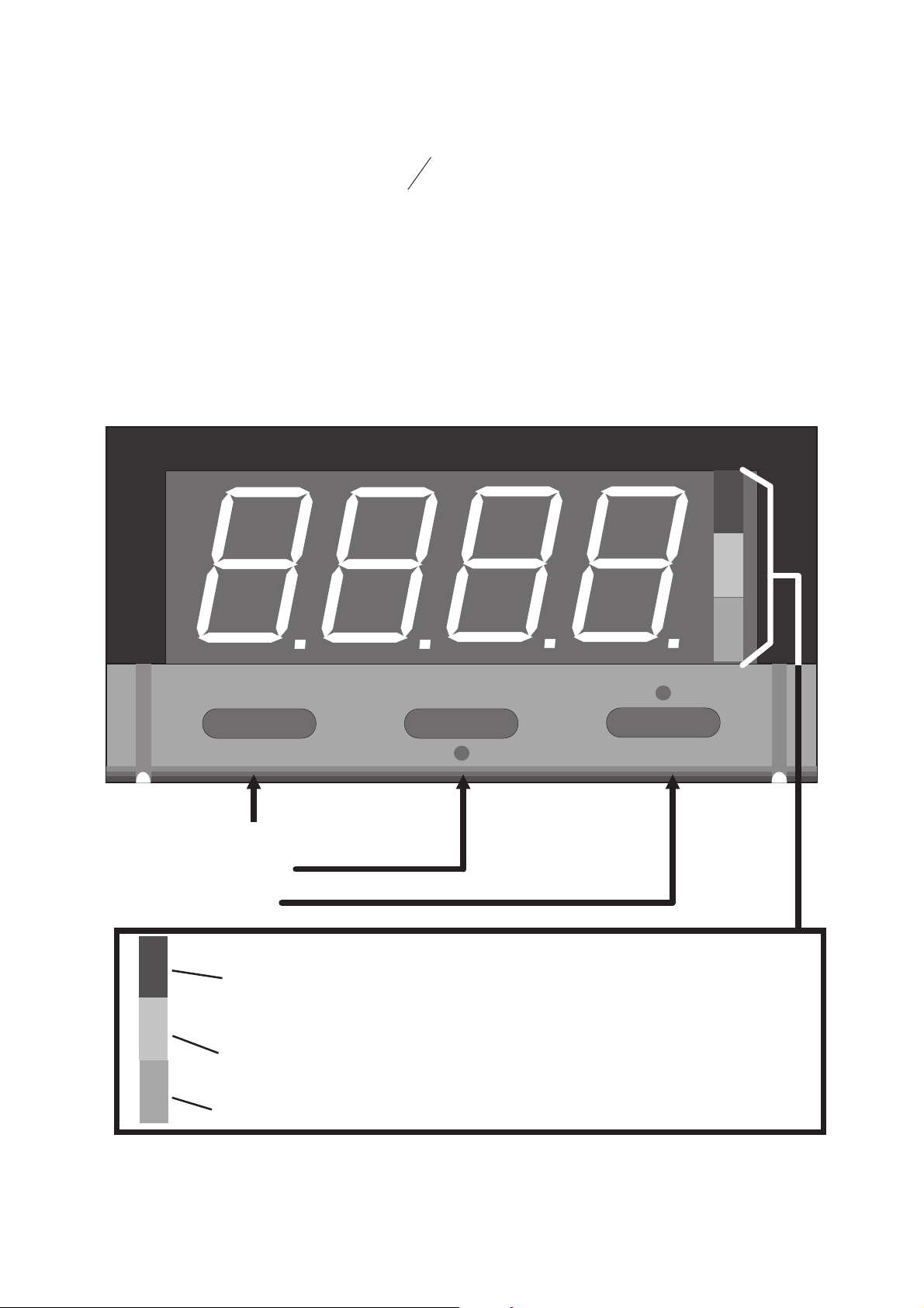
Scroll Key
Down key
Up key
INDICATORS
Green: OFF - Process Variable less than
Setpoint
ON - Process Variable equals Setpoint
Flashing - Process Variable greater than
Setpoint
Yellow: OFF - Normal Operation
OM076 Page 1 June 1997
Page 2
1/32-DIN Temperature Controller
Operator's Manual
1 NORMAL OPERATION (Yellow LED OFF)
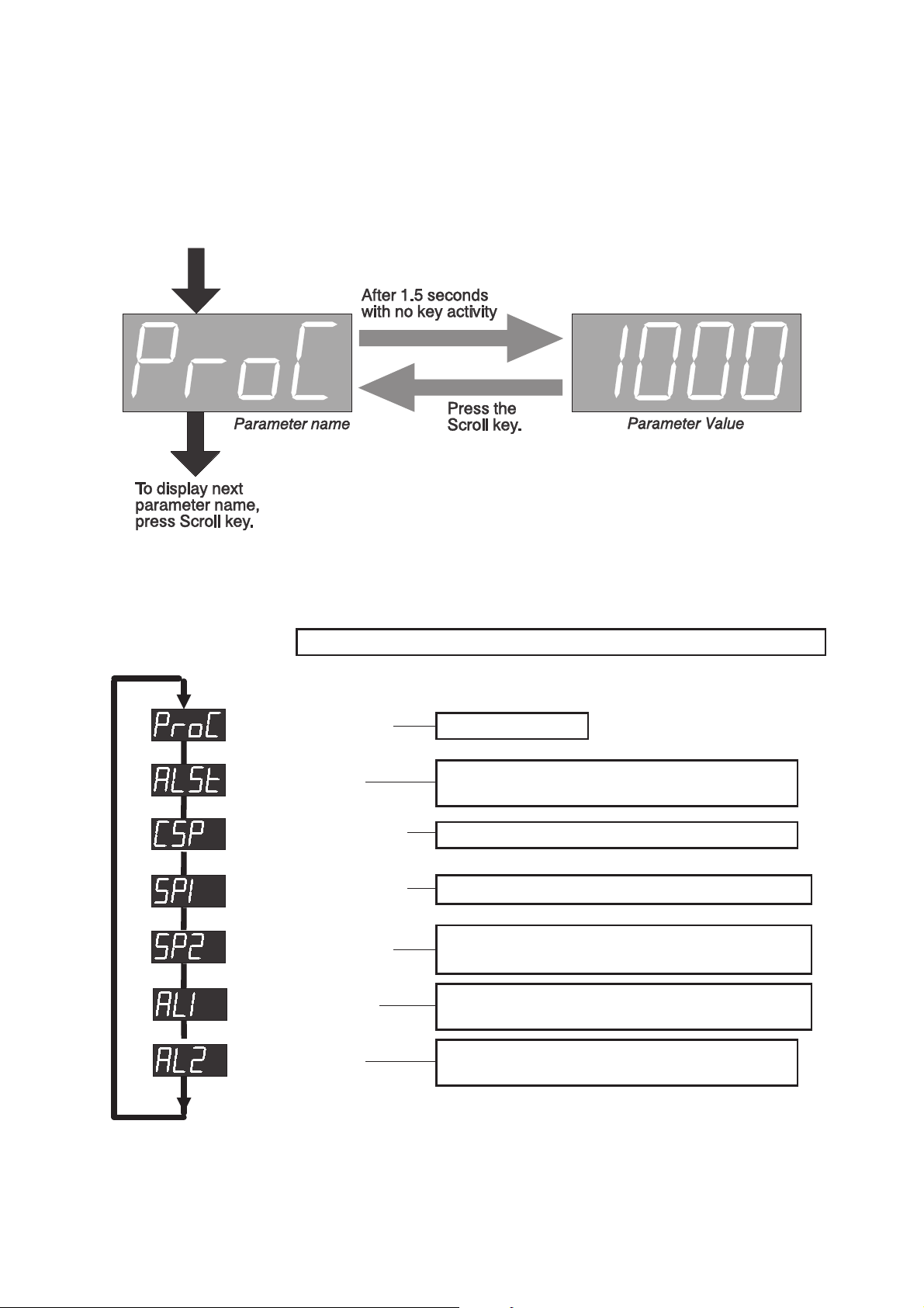
In this mode, the display normallyshowstheprocessvariablevalue.UsetheScrollkeyto
step through a sequence of parameters as follows:
The following parameters are available in Normal Operation:
Scroll key steps through displays; Up/Down keys adjust displayed values.
Process Variable
Alarm Status
Not adjustable
Included only if two alarms configured
and if either or both is (are) active.
Setpoint Selection
Setpoint (1)
Setpoint 2
Included only if Dual Setpoint configured
Adjustable only if enabled (see Section 2)
Included only if Dual Setpoint configured;
adjustable only if enabled (see Section 2)
Alarm (1) value
Included only if enabled (see Section 2)
and an alarm is configured
Alarm 2 value
Included only if enabled (see Section 2)
and two alarms are configured
June 1997 Page 2 OM076
Page 3
1/32-DIN Temperature Controller
Operator's Manual
1.1 Easy Tune
If the Controller has been configured for Easy Tune operation, all tuning is executed
automatically; no operator action is required.
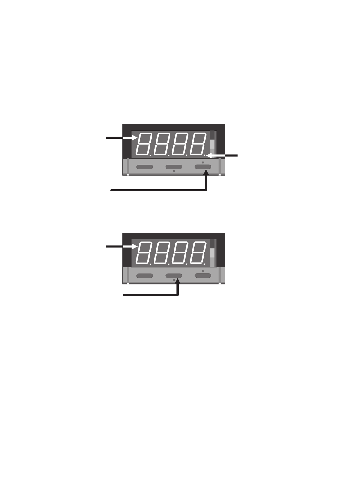
1.2 Manual Tuning with Pre-Tune
When the Controller is configured for Manual Tuning, the Pre-Tune facility is available.
Pre-Tune is used to optimise system start-up (normally after power-up or after a major
change to the process being controlled). To activate Pre-Tune:
1. Select the
Process Variable
display.
2. Press Up key.
NOTE: Pre-Tune cannot be activated if the ProcessVariableiswithin5%of
input span from the setpoint.
To dis-engage Pre-Tune:
1. Select the
Process Variable
display.
2. Press the Down key.
This decimal point
indicator will flash
whilst Pre-Tune is
active.
NOTE: Pre-Tune is a single-shot operation and, therefore, when it is
completed, Pre-Tune will dis-engage itself automatically.
OM076 Page 3 June 1997
Page 4
1/32-DIN Temperature Controller
Operator's Manual
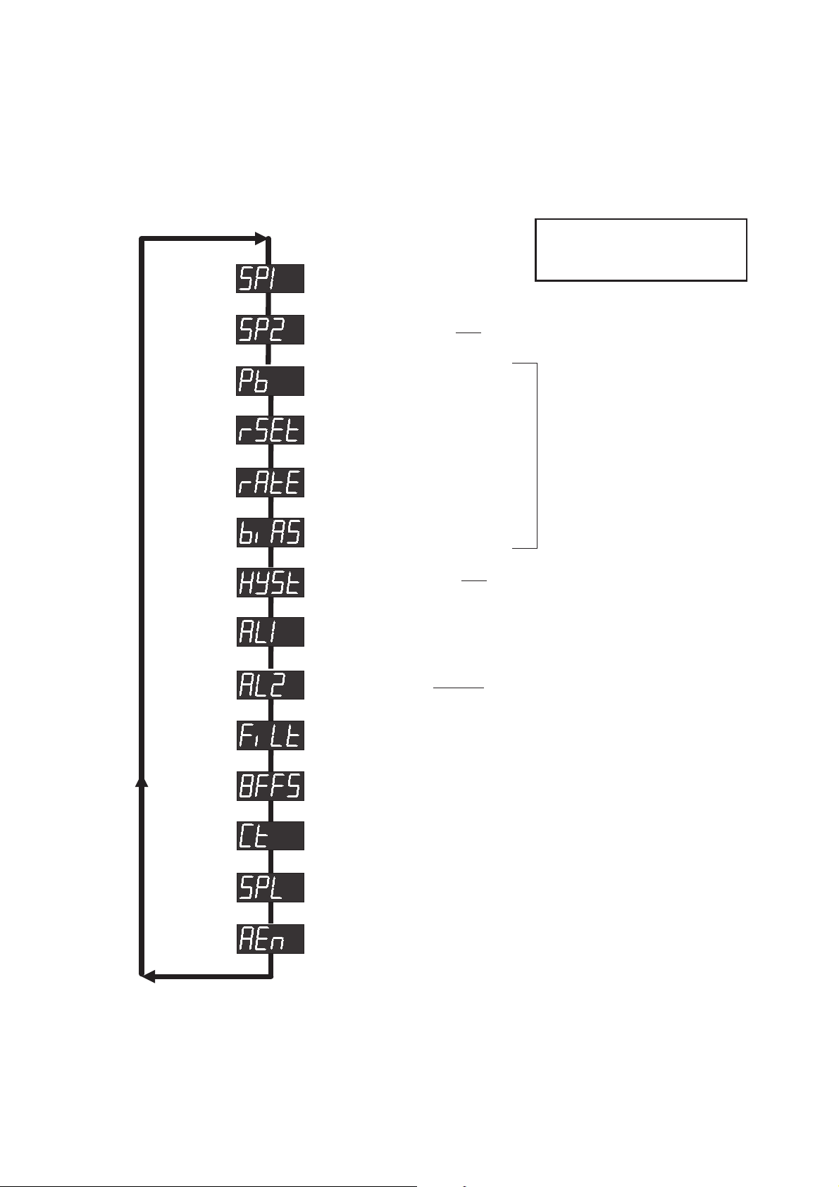
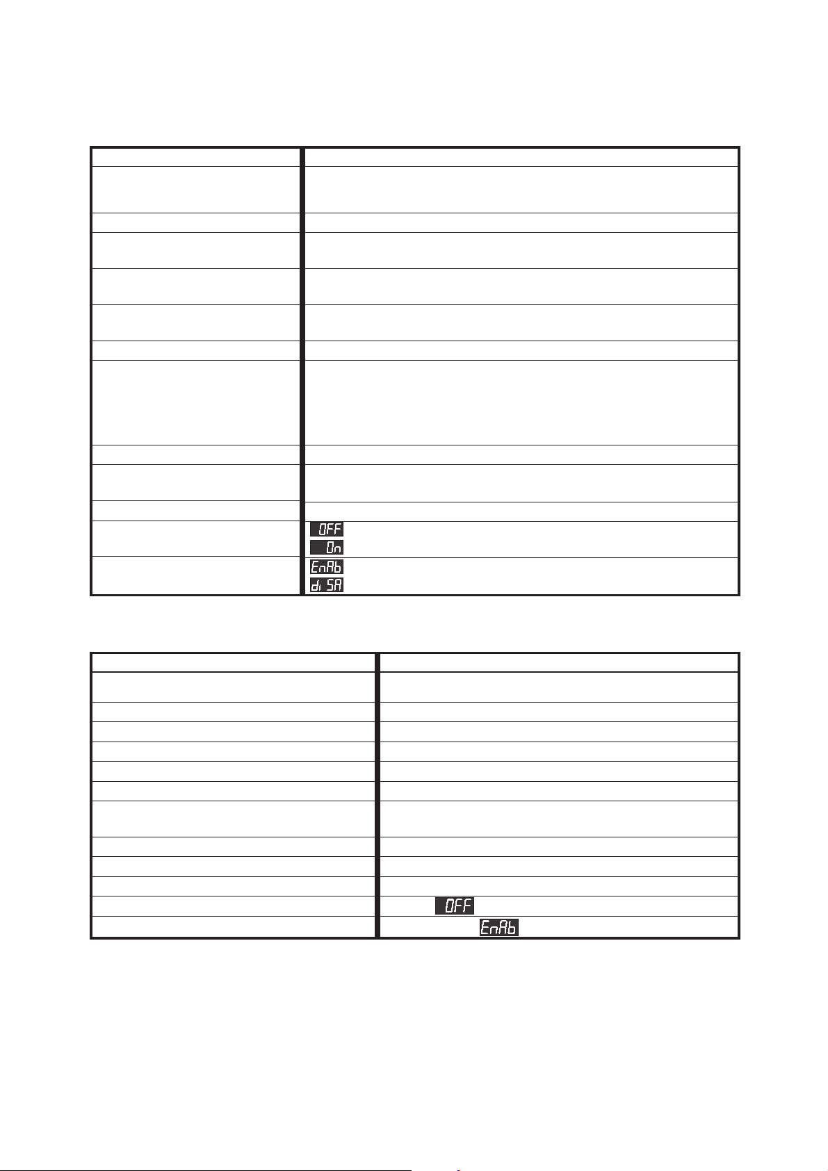
2 CONTROL SETUP (Yellow LED ON)
To enter Control Setup mode, press the Upand Down keys simultaneously for more than
three seconds. The same key action exits this mode. The parameters are as follows:
Scroll key steps through
displays; Up/Down keys adjust
displayed values.
Setpoint (1) value
Setpoint 2 value
Proportional
Band value
Reset (Integral) value
Rate (Derivative)
Bias (Manual Reset)
ON/OFF
Hysteresis value
Alarm 1 value
Alarm 2 value
Appears only if Dual Setpoint
operation is configured.
Appear only if Manual
Tuning and PID Control
are configured.
Appears only if ON/OFF
Control is configured.
Appears only if two alarms are
configured.
Input Filter Time Constant value
Input Offset value
Output Cycle Time value
Setpoint Lock
Disable/enable access to Alarm Value in
Normal Operation mode
June 1997 Page 4 OM076
Page 5
2.1 Adjustment Ranges
1/32-DIN Temperature Controller
Operator's Manual
Parameter
Setpoint(s)
Proportional Band
Reset
Rate
Bias
(Manual Reset)
ON/OFF Hysteresis
Alarm (1 & 2) level
Input Filter Time Constant
Input Offset
Output Cycle Time
Setpoint Lock
Alarm Value Display
Enable/Disable
Adjustment Range
Input Range Min. to Input Range Max.
NOTE: Negative values limited by display to –1999
0.5% to 999.9% (0.1% increments)
1 sec. to 99 min. 59 sec.
and OFF (>99min. 59 secs.)
0 (OFF) to 99 min. 59 sec.
0% to 100%
0.1% to 10.0% of input span
Process High: Input Range Min. to Input Range Max.
Process Low: Input Range Min. to Input Range Max.
Deviation (High or Low): –(input span) to +(input span)
Band: 1 LSD to Input Span
NOTE: Negative values limited by display to –1999
0sec. to 100sec.
±input span
NOTE: Negative values limited by display to –1999
0.5 (SSR only), 1, 2, 4, 8, 16, 32, 64, 128, 256 & 512 sec.
adjustment enabled in Normal Operation
adjustment disabled in Normal Operation
display/adjustment enabled in Normal Operation
display/adjustment disabled in Normal Operation
2.2 Default Values/Settings
Parameter
Setpoint(s)
Proportional Band
Reset
Rate
Bias (Manual Reset)
ON/OFF Hysteresis
Alarm (1 & 2) level
Input Filter Time Constant
Input Offset
Output Cycle Time
Setpoint Lock
Alarm Value Display Enable/Disable
Default Value/Setting
Input Range Min.
10.0%
5 minutes
1 minute 15 seconds
25%
0.5% of input span
Alarm 1 Process High: Input Range Max.
Alarm 2 Process Low: Input Range Min.
2 seconds
0
16 seconds
(adjustment enabled)
(enabled)
OM076 Page 5 June 1997
Page 6

1/32-DIN Temperature Controller
Operator's Manual
June 1997 Page 6 OM076
Page 7

Régulateur de Température 24mm x 48mm (1/32-DIN)
Manuel d’Utilisation
REGULATEUR DE TEMPERATURE
24 X 48mm (
1
-DIN)
32
MANUEL D’UTILISATION
Part No. 59096
Touche de Scrutation
Touche de Décrémentation
Touche d’Incrémentation
LEDs
Vert: OFF - Mesure < Consigne
ON - Mesure = Consigne
Clignotant - Mesure > Consigne
Jaune: OFF - Mode Fonctionnement
ON - Mode Réglage
Rouge: Clignotant - Alarme(s) active(s)
OM0076 Page 1 Décembre 1997
Page 8

Régulateur de Température 24mm x 48mm (1/32-DIN)
Manuel d’Utilisation
1 MODE FONCTIONNEMENT (LED Jaune est sur OFF)
Dans ce mode, l’afficheur indique la valeur de la mesure. Appuyer sur la touche de
Scrutation pour faire dérouler les paramètres comme suite:
Les paramètres suivant sont accessibles en Mode Fonctionnement:
La touche de Scrutation provoque le changement d’affichage.
Les touches d’Incrémentation et de Décrémentation font changer la valeur.
Mesure
Etat des Alarmes
Lecture uniquement
Apparaît si les 2 alarmes sont
configurées et si 1 ou les 2 sont activées.
Choix de la
Consigne
Consigne 1
Apparaît si la double consigne est
configurée.
Valeur modifiable si autorisée
(voir Section 2)
Consigne 2
Alarme 1
Apparaît si la consigne 2 est configurée;
Apparaît si l’Alarme 1 est configurée et
autorisée (voir Section 2)
Alarme 2
Apparaît si autorisée et si les 2 alarmes
sont configurée (voir Section 2)
Décembre 1997 Page 2 OM0076
Page 9

Régulateur de Température 24mm x 48mm (1/32-DIN)
Manuel d’Utilisation
1.1 Autoadaptatif Automatique
Lorsquelerégulateurest configuréen fonctionnementautoadaptatif automatique,aucune
action de la part de l’utilisateur n’est nécessaire.
1.2 Autoadaptatif Manuel avec Préréglage
Lorsque le régulateur est configuré en autoadaptatif manuel, un préréglage est
souhaitable. Le préréglage est utilisée pour optimiser le système au démarrage
(normalement après la mise sous tension ou à un changement majeur du process). Pour
activer le préréglage:
1. Affichage
de la mesure
sélectionnée.
2. Appuyer sur la
touche
d’Incrémentation.
Cette virgule
clignote lorsque le
préréglage est
active.
NOTA:Le préréglagene peutêtreactivéquesi lamesure estau moinsà 5%
de l’échelle d’entrée de la valeur de la consigne.
Annulation du préréglage:
1. L’affichage de
la mesure
sélectionnée.
2. Appuyer sur la
touche de
Décrémentation.
NOTA:Le préréglageest effectuéen uneseule opération;donc,l’annulation
du préréglage se fait automatiquement.
OM0076 Page 3 Décembre 1997
Page 10

Régulateur de Température 24mm x 48mm (1/32-DIN)
Manuel d’Utilisation
2 MODE REGLAGE (LED jaune est sur ON)
Pouraccéder auMode Réglage,appuyer simultanémentsur lestouchesd’Incrémentation
et de Décrémentation pendant au noins 3 secondes. La même opération est à faire pour
quitter le Mode Réglage. Les paramètres accessibles sont:
La touche de Scrutation provoque
le changement d’affichage;
Les touches d’Incrénentation et de
Valeur de Consigne
Décrémentation font changer la
valeur.
Valeur de Consigne
Bande
Proportionell
Intégrale
Temps de Dérivée
Centrage de Bande
Valeur
Valeur Alarme 1
Valeur Alarme 2
N’apparaît que si double
consigne est configurée.
N’apparaît que
autoadaptatif manuel et
réglage PID sont
configurés.
N’apparaît que si réglage
ON/OFF est configuré.
N’apparaît que si 2 alarmes
sont configurées.
Constant de Filtre Numérique
Décalage de la Mesure
Temps de Cycle
Verrouillage de la Consigne
Accès Valeur de l’Alarme
Décembre 1997 Page 4 OM0076
Page 11

Régulateur de Température 24mm x 48mm (1/32-DIN)
Manuel d’Utilisation
2.1 AJUSTEMENT DE L’ECHELLE
Paramètre
Consigne(s)
Bande Proportionelle
Intégrale
Temps de Dérivée
Centrage de Bande
Hystérésis ON/OFF
Valeur de l’Alarme
(1 et 2)
Constante Filtre
Numérique
Décalage de la
Mesure
Temps de Cycle
Verrouillage
Consigne
Accèss Valeur
d’Alarme
Ajustement de l’Echelle
Echelle d’entrée mini. à échelle d’entrée maxi.
NOTA: Valeur négative limitée par l’affichage à –1999
0.5% à 999,9% (par pas de 0,1%)
1 seconde à 99 minutes 59 secondes
et OFF (>99minutes 59 secondes)
0(OFF) à 99 minutes 59 secondes
0% à 100%
0,1% à 10,0% de l’échelle
Process Haute/Process Basse: échelle d’entrée mini. à échelle
d’entrée maxi.
Déviation (Haute ou Basse): –(échelle d’entrée) à +(échelle
d’entrée)
Bande: 1 digit à échelle d’entrée
NOTA: Valeur négative limitée par l’affichage à –1999
0 seconde à 100 secondes
l’échelle d’entrée
NOTA: Valeur négative limitée par l’affichage à –1999
0,5 (SSR seul), 1, 2, 4, 8, 16, 32, 64, 128, 256 & 512 sec.
Modification de consigne en Mode Fonctionnement
Pas de modification Mode Fonctionnement
affichage/modification possible en Mode Fonctionnement
affichage/modification bloqués en Mode Fonctionnement
2.2 VALEURS DES PARAMETRES PAR DEFAUT
Paramètre
Consigne(s)
Bande Proportionnelle
Intégrale
Temps de Dérivée
Centrage de Bande
Hystérésis ON/OFF
Valeur de l’Alarme (1 et 2)
Alarme 1 - Process Haute: Echelle d’Entrée Maxi.
Valeur par Défaut
Echelle d’Entrée Mini.
10,0%
5 minutes
1 minute 15 secondes
25%
0,5% de l’Echelle d’Entrée
Alarme 2 - Process Basse: Echelle d’Entrée Mini.
Constante Filtre Numérique
Decalage de la Mesure
Tenmps de Cycle
Verrouillage Consigne
Accès Valeur d’Alarme
OM0076 Page 5 Décembre 1997
Modification de consigne
Affichage/modification possible
2 secondes
0
16 secondes
Page 12

Régulateur de Température 24mm x 48mm (1/32-DIN)
Manuel d’Utilisation
Décembre 1997 Page 6 OM0076
Page 13

Mini Industrieregler und Anzeiger (1/32-DIN)
Bedienungsanleitung
MINI INDUSTRIEREGLER UND
ANZEIGER (
1
-DIN)
32
BEDIENUNGSANLEITUNG
Part No. 59096
Scroll-Taste
AB-Taste
AUF-Taste
ANZEIGE
Grun: AUS - Istwert < Sollwert
AN - Istwert = Sollwert
Blinkend - Istwert > Sollwert
Gelb: AUS - Normalbetrieb
AN - Einstelllungsbetrieb
Rot: Blinkt bei aktivierten Alarmen
OM076G Seite 1 December 1997
Page 14

Mini Industrieregler und Anzeiger
Bedienungsanleitung
1 NORMALBETRIEB (Gelb LED AUS)
Nornalische, in diesen Mode, die Anzeige zeigt der Istwert. Mit Hilfe der Scroll-Taste
können die Parameter in Reihenfolge angezeigt werden:
Die Reihenfolge der Parameter im Normalbetrieb ist:
Scroll-Taste = Parameterauswahl; AUF- und AB-Taste = Werteinstellung.
Istwert
Alarmstatus
Nur Anzeige.
Nur bei Geräten mit 2 Alarmen und ein
alarm aktiv ist.
Sollwertauswah
Sollwert 1
Sollwert 2
Nur wenn Wechselsollwert gekonfigiert ist.
Einstellbar wenn möglich (siehe Kapitel 2).
Nur wenn Wechselsollwert konfiguriert ist.
Einstellbar wenn möglich (siehe Kapitel 2).
Alarm 1
Nur wenn möglich (siehe Kapitel 2) und 1
alarm konfiguriert ist.
Alarm 2
Nur wenn möglich (siehe Kapitel 2) und 2
alarmen konfiguriert sind.
December 1997 Seite 2 OM076G
Page 15

Mini Industrieregler und Anzeiger (1/32-DIN)
Bedienungsanleitung
1.1 Easy Tune
Wenn das Gerät mit Easy Tune konfiguriert ist, alle abgleichung automatische ist.
1.2 Manuelle Abgleichung (Automatische Vorabgleich möglich)
Wenn dar Gerät für Manuelle Abgleichung konfiguriert ist, Automatische Vorabgleich ist
möglich. Um Automatische Vorabgleich zu aktivieren, gehen Sie wie folgt vor:
1. Auswahlen Sie
der Istwertzeigt.
Wenn Vorabgleich ist
aktiv, diese
dezimalpunktindikator
blinkt.
2. Betätigen Sie die AUF-Taste.
ANMERKUNG: Für die Zuschaltung des Vorabgleichs ist eine
Soll-Istwert-Differenz von 5% (des Meßbereiches) erforderlich.
1. Auswahlen Sie
der Istwertzeigt.
2. Betätigen Sie die AB-Taste.
Um Vorabgleich zu beenden:
ANMERKUNG: Der Vorabgleich wird nur einmal aktiviert. Die Funktion
schaltet sich selbsttätig aus, wenn sie durchgeführt ist.
OM076G Seite 3 December 1997
Page 16

Mini Industrieregler und Anzeiger
Bedienungsanleitung
2 EINSTELLUNGSBETRIEB (Gelb LED AN)
Zu Einstellungsbetrieb auswählen, betätigen Sie die AUF- und AB-Tasten gleichzeitig
nach 3 Sekunden minimum. Dieselbe Tastenwirkung verlasst Einstellungsbetrieb. Die
Reihenfolge der Parameter ist:
Scroll-Taste = Parameterauswahl;
AUF- und AB-Taste = Werteinstellung.
Sollwert 1
Sollwert 2
Proportionalband
Integralzeitkonstante
Differentialzeitkonstante
xpArbeitspunkt (Bias)
EIN/AUS
Regelunghysterese
Alarm 1
Alarm 2
Nur wenn Wechselsollwert
gekonfigiert ist.
Nur wenn Manuelle
Abgleich und
PID-regelung sind
konfiguriert
Appears only if ON/OFF
Control is configured.
Appears only if two alarms are
configured.
Digitalfilterzeitkonstante
Istwert Offset
Ausgangproportionalzeit
Sollwertverriegelung
Lähmen/befähigen der Zugang zu Alarmwert im
Normalbetrieb.
December 1997 Seite 4 OM076G
Page 17

Mini Industrieregler und Anzeiger (1/32-DIN)
2.1 Verstellbereiche
Parameter
Bedienungsanleitung
Verstellbereich
Sollwert(en)
Proportionalband
Integralzeitkonstante
Differentialzeitkonstante
xpArbeitspunkt
(Bias)
EIN/AUS
Regelunghysterese
Alarm (1 und 2)
Digitalfilterzeitkonstante
Istwert Offset
Ausgang-
proportionalzeit
Sollwert-
verriegelung
Lähmen/befähigen
der Zugang zu
Alarmwert im
Normalbetrieb.
Min. Eingangsbereich bis Max. Eingangsbereich
ANMERKUNG: Negativwerte beschränkt auf –1999
0,5% bis 999,9% (0,1% Zunahmen)
1 Sekunde bis 99 Minuten 59 Sekunden
und OFF (>99Minuten 59 Sekunden)
0(OFF) bis 99 Minuten 59 Sekunden
0% bis 100%
0,1% bis 10,0% des Eingangsbereichs
Proceßalarm Übersollwert oder Untersollwert:
Eingangsbereich Min. bis Eingangsbereich Max.
Abweichungsalarm: –(Eingangsbereich) bis +(Eingangsbereich)
Bandalarm: 1 digit bis Eingangsbereich
ANMERKUNG: Negativwerte beschränkt auf –1999
0 Sekunde bis 100 Sekunden.
Eingangsbereich
ANMERKUNG: Negativwerte beschränkt auf –1999
0.5 (nur SSR), 1, 2, 4, 8, 16, 32, 64, 128, 256 & 512 Sekunden
Einstellung möglich im Normalbetrieb
Einstellung nicht möglich im Normalbetrieb
Alarmwertzeigt/Einstellung möglich im Normalbetrieb
Alarmwertzeigt/Einstellung nicht möglich im
Normalbetrieb
2.2 Grundeinstellunge
Parameter
Sollwert(en)
Proportionalband
Integralzeitkonstante
Differentilazeitkonstante
xpArbeitspunkt (Bias)
EIN/AUS Regelunghysterese
Alarm (1 und 2)
Proceßalarm 1 Übersollwert: Eingangsbereich Max.
Grundeinstellung
Min. Eingangsbereich
10,0%
5 Minuten
1 Minute 15 Sekunden
25%
0,5% des Eingangsbereich
Proceßalarm 2 Untersollwert: Eingangsbereich Min.
Digitalfilterzeitkonstante
Istwert Offset
Ausgangproportionalzeit
Sollwertverriegelung
Lähmen/befähigen der Zugang
(Alarmwertzeigt/Einstellung möglich)
2 Sekunden
0
16 Sekunden
(Einstellung möglich)
zu Alarmwert im Normalbetrieb.
OM076G Seite 5 December 1997
Page 18

Mini Industrieregler und Anzeiger
Bedienungsanleitung
December 1997 Seite 6 OM076G
 Loading...