

Westcode Semiconductors N4803FC300-350 Data Sheet
Date:- 25 Jul, 2002
WESTCODE
An IXYS Company
Phase Control Thyristor
Type N4803FC300-350
Old Type No.: N1683CH29-35
Absolute Maximum Ratings
VOLTAGE RATINGS
V
DRM
V
DSM
V
RRM
V
RSM
I
T(AV)
I
T(AV)
I
T(AV)
I
T(RMS)
I
T(d.c.)
I
TSM
I
TSM2
I2tI
I2t
diT/dt
V
RGM
P
G(AV)
P
GM
V
GD
T
HS
T
stg
Repetitive peak off-state voltage, (note 1) 3000-3500 V
Non-repetitive peak off-state voltage, (note 1) 3000-3500 V
Repetitive peak reverse voltage, (note 1) 3000-3500 V
Non-repetitive peak reverse voltage, (note 1) 3100-3600 V
OTHER RATINGS
Mean on-state current. T
Mean on-state current. T
Mean on-state current. T
Nominal RMS on-state current. T
D.C. on-state current. T
Peak non-repetitive surge tp=10ms, Vrm=0.6V
Peak non-repetitive surge tp=10ms, Vrm≤10V, (note 5)
2
t capacity for fusing tp=10ms, Vrm=0.6V
2
I
t capacity for fusing tp=10ms, Vrm≤10V, (note 5)
Maximum rate of rise of on-state current (repetitive), (Note 6) 150 A/µs
Maximum rate of rise of on-state current (non-repetitive), (Note 6) 300 A/µs
Peak reverse gate voltage 5 V
Mean forward gate power 5 W
Peak forward gate power 50 W
Non-trigger gate voltage, (Note 7) 0.25 V
Operating temperature range -40 to +125 °C
Storage temperature range -40 to +150 °C
=55°C, (note 2) 4803 A
sink
=85°C, (note 2) 3356 A
sink
=85°C, (note 3) 2072 A
sink
=25°C, (note 2) 9453 A
sink
=25°C, (note 4) 8362 A
sink
Data Sheet Issue:- 1
MAXIMUM
MAXIMUM
, (note 5) 60 kA
RRM
, (note 5) 18.0×10
RRM
LIMITS
LIMITS
67 kA
6
22.5×10
6
UNITS
UNITS
A2s
A2s
Notes: -
1) De-rating factor of 0.13% per °C is applicable for T
2) Double side cooled, single phase; 50Hz, 180° half-sinewave.
3) Single side cooled, single phase; 50Hz, 180° half-sinewave.
4) Double side cooled.
5) Half-sinewave, 125°C T
6) V
=67% V
D
7) Rated V
Data Sheet. Type N4803FC300-350 Issue 1 Page 1 of 10 July, 2002
, ITM=1000A, IFG=2A, tr≤0.5µs, T
DRM
.
DRM
initial.
j
below 25°C.
j
=125°C.
case
WESTCODE
WESTCODE An IXYS Company Phase Control Thyristor Types N4803FC300-350
WESTCODEWESTCODE
Characteristics
PARAMETER MIN. TYP. MAX. TEST CONDITIONS (Note 1) UNITS
V
Maximum peak on-state voltage - - 1.6 ITM=6000A V
TM
V
Threshold voltage - - 0.92 V
0
r
Slope resistance - - 0.11
S
dv/dt Critical rate of rise of off-state voltage 1000 - - VD=80% V
I
Peak off-state current - - 300 Rated V
DRM
I
Peak reverse current - - 300 Rated V
RRM
V
Gate trigger voltage - - 3.0 V
GT
I
Gate trigger current - - 300
GT
I
Holding current - - 1000 Tj=25°C mA
H
t
Gate controlled turn-on delay time - 1.0 2.0
gd
t
Turn-on time - 2.0 3.0
gt
Q
Recovered Charge - 12000 - µC
rr
Q
Recovered Charge, 50% chord - 7000 10500 µC
ra
I
Reverse recovery current - 280 - A
rm
t
Reverse recovery time, 50% chord - 50 -
rr
- 620 -
t
Turn-off time
q
- 850 -
Thermal resistance, junction to
R
θ
heatsink
- - 0.0065 Double side cooled K/W
- - 0.013 Single side cooled K/W
=25°C, VD=10V, IT=3A
T
j
=2A, tr=0.5µs, VD=67%V
I
FG
I
=2000A, di/dt=10A/µs, Tj=25°C
TM
I
=4000A, tp=2ms, di/dt=10A/µs, Vr=50V
TM
ITM=4000A, tp=2ms, di/dt=10A/µs,
V
=50V, Vdr=67%V
r
ITM=4000A, tp=2ms, di/dt=10A/µs,
V
=50V, Vdr=67%V
r
, Linear ramp, gate o/c
DRM
DRM
RRM
, dVdr/dt=20V/µs
DRM
, dVdr/dt=200V/µs
DRM
DRM
,
F Mounting force 81 - 99 kN
WtWeight - 2.8 - kg
mΩ
V/µs
mA
mA
mA
µs
µs
µs
Notes: -
1) Unless otherwise indicated T
Data Sheet. Type N4803FC300-350 Issue 1 Page 2 of 10 July, 2002
=125°C.
j
WESTCODE
WESTCODE An IXYS Company Phase Control Thyristor Types N4803FC300-350
WESTCODEWESTCODE
Notes on Ratings and Characteristics
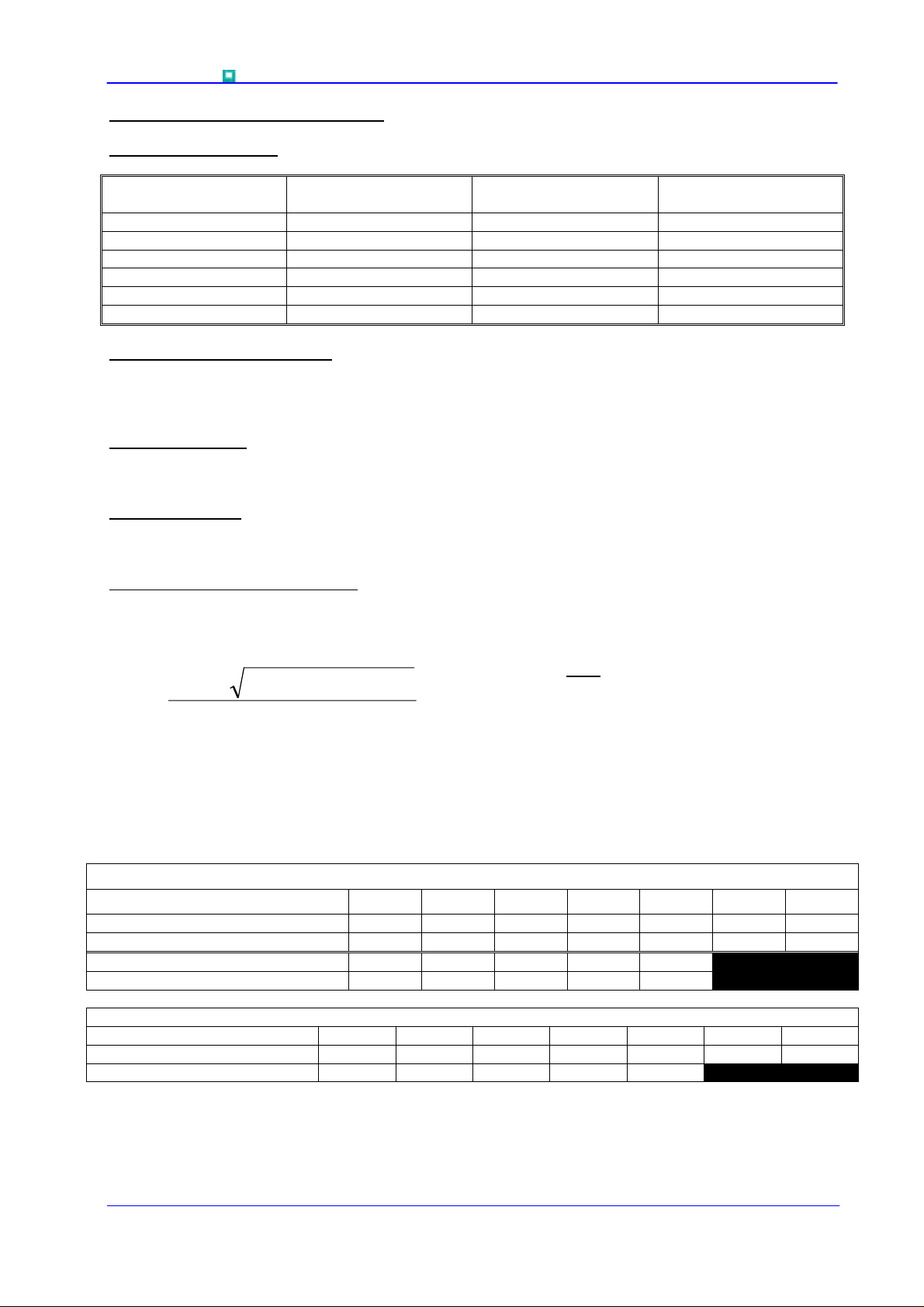
1.0 Voltage Grade Table V
Voltage Grade
30 3000 3100 1860
31 3100 3200 1920
32 3200 3300 1980
33 3300 3400 2040
34 3400 3500 2100
35 3500 3600 2160
2.0 Extension of Voltage Grades
This report is applicable to other and higher voltage grades when supply has been agreed by
Sales/Production.
3.0 De-rating Factor
A blocking voltage de-rating factor of 0.13%/°C is applicable to this device for Tj below 25°C.
4.0 Repetitive dv/dt
Standard dv/dt is 1000V/µs.
5.0 Computer Modelling Parameters
5.1 Device Dissipation Calculations
DRM VDSM VRRM
V
V
RSM
V
V
V
D
DC V
R
T
WrffVV
4
I
=
AV
Where V0=0.92V, rs=0.11mΩ,
R
= Supplementary thermal impedance, see table below.
th
00
rff
2
⋅⋅
⋅⋅⋅++−
AVs
and:
s
W
AV
=
∆
R
th
max
TTT
−=∆
Hsj
ff = Form factor, see table below.
Supplementary Thermal Impedance
Conduction Angle 30° 60° 90° 120° 180° 270° d.c.
Square wave Double Side Cooled 0.00717 0.00707 0.00698 0.00689 0.00673 0.00652 0.0065
Square wave Single Side Cooled 0.0137 0.01359 0.01349 0.0134 0.01323 0.01301 0.013
Sine wave Double Side Cooled 0.00709 0.00697 0.00687 0.00678 0.00654
Sine wave Single Side Cooled 0.0136 0.01348 0.01337 0.01328 0.01303
Form Factors
Conduction Angle 30° 60° 90° 120° 180° 270° d.c.
Square wave 3.46 2.45 2 1.73 1.41 1.15 1
Sine wave 3.98 2.78 2.22 1.88 1.57
Data Sheet. Type N4803FC300-350 Issue 1 Page 3 of 10 July, 2002
 Loading...