

Westcode Semiconductors M2408N#020, M2408N#060 Data Sheet
EVALUATION LABORATORY
Rating Report
Origin
Issue 2
-
PAR 985
-
Date
Total Pages
23 July, 2004
-
13
-
Fast Recovery Diode
Types M2408N#020 to M2408N#060
Old Type No.: SM02-06CXC504
Author EL Check/Approval QA Approval S & M Approval
N. A. Tarling
Abstract
The M2408N#020-060 fast recovery diode consists of a 50mm diameter silicon slice (manufacturing
reference FFA), mounted in a cold weld caps ule. It has soft recovery characteristics and low values of
stored charge.
Summary of changes to previous issue.
Issue 1
Issue 2 Addition of ‘D’ Housing option (21mm Clamp height)
The information contained herein is confidential and is protected by Copyright. The information may not be
used or disclosed except with the written permis sion of and in the manner permitted by the propr ietors
Westcode Semiconductors Ltd.
In the interest of product im provement, W estcode res erves the right to change specif ications at any time
without prior notice.
Devices with a suffix code (2-letter, 3-letter or letter/digit/letter combination) added to their generic code
are not necessarily subject to the conditions and limits contained in this report.
First issue – Device T
Previous Datasheet M1825NC020-060 (June 2004) is now obsolete
uprated to 150°C. All ratings reflect this change.
JMAX
Rating Report. Types M2408N#020 to M2408N#060 Issue 2 Page i July, 2004

Contents
Abstract......................................................................................................................................................... i
Contents.......................................................................................................................................................ii
Absolute Maximum Ratings....................................................................................................................... 1
Characteristics ............................................................................................................................................2
Notes on Ratings and Characteristics......................................................................................................3
1.0 Voltage Grade Table ........................................................................................................................... 3
2.0 De-rating Factor...................................................................................................................................3
3.0 ABCD Constants ................................................................................................................................. 3
4.0 Reverse recovery ratings.....................................................................................................................3
5.0 Reverse Recovery Loss ......................................................................................................................4
NOTE 1 - Reverse Recovery Loss by Measurement...............................................................................................................4
6.0 Snubber Components.......................................................................................................................... 4
7.0 Computer Modelling Parameters.........................................................................................................5
7.1 Device Dissipation Calculations.........................................................................................................................................5
7.2 Calculation of V
using ABCD Coefficients.......................................................................................................................5
F
8.0 Frequency Ratings...............................................................................................................................5
9.0 Square wave ratings............................................................................................................................ 5
10.0 Duty cycle lines.................................................................................................................................. 5
Curves..........................................................................................................................................................6
Figure 1 – Forward characteristics of Limit device.................................................................................... 6
Figure 2 – Maximum forward recovery voltage .........................................................................................6
Figure 3 - Recovered charge, Q
Figure 4 - Recovered charge, Q
Figure 5 - Maximum reverse current, I
Figure 6 - Maximum recovery time, t
..............................................................................................................6
rr
(50% chord)......................................................................................... 6
ra
...................................................................................................7
rm
(50% chord)................................................................................... 7
rr
Figure 7 – Reverse recovery energy per pulse..........................................................................................7
Figure 8 - Sine wave energy per pulse...................................................................................................... 7
Figure 9 - Sine wave frequency vs. pulse width, 55°C heatsink................................................................ 8
Figure 10 - Sine wave frequency vs. pulse width, 85°C heatsink.............................................................. 8
Figure 11 - Square wave energy per pulse, 100A/µs................................................................................ 8
Figure 12 - Square wave energy per pulse, 500A/µs................................................................................ 8
Figure 13 - Square wave frequency vs. pulse width, 55°C heatsink, 100A/µs.......................................... 9
Figure 14 - Square wave frequency vs. pulse width, 55°C heatsink, 500A/µs.......................................... 9
Figure 15 - Square wave frequency vs. pulse width, 85°C heatsink, 100A/µs.......................................... 9
Figure 16 - Square wave frequency vs. pulse width, 85°C heatsink, 500A/µs.......................................... 9
Figure 17 – Maximum surge and I
2
t ratings.............................................................................................10
Figure 18 – Transient thermal impedance............................................................................................... 10
Outline Drawing & Ordering Information................................................................................................11
Rating Report. Types M2408N#020 to M2408N#060 Issue 2 Page ii July, 2004

Date:- 23 Jul, 2004
WESTCODE
An IXYS Company
Fast Recovery Diode
Type M2408N#020 to M2408N#060
Old Type No.: SM02-06CXC504
Absolute Maximum Ratings
VOLTAGE RATINGS
V
RRM
V
RSM
I
F(AV)M
I
F(AV)M
I
F(AV)M
I
F(RMS)
I
F(d.c.)
I
FSM
I
FSM2
I2tI
I2t
T
j op
T
stg
Repetitive peak reverse voltage, (note 1) 200-600 V
Non-repetitive peak reverse voltage, (note 1) 300-700 V
OTHER RATINGS
Maximum average forward current, T
Maximum average forward current. T
Maximum average forward. T
Nominal RMS forward current, T
D.C. forward current, T
Peak non-repetitive surge tp=10ms, VRM=60%V
Peak non-repetitive surge tp=10ms, VRM≤10V, (note 5)
2
t capacity for fusing tp=10ms, VRM=60%V
2
I
t capacity for fusing tp=10ms, VRM≤10V, (note 5)
Operating temperature range -40 to +150 °C
Storage temperature range -40 to +150 °C
sink
=100°C, (note 3) 857 A
sink
=25°C, (note 4) 3736 A
=55°C, (note 2) 2408 A
sink
=100°C, (note 2) 1497 A
sink
=25°C, (note 2) 4585 A
sink
, (note 5) 24.0 kA
RRM
, (note 5) 2.88×10
RRM
Data Sheet Issue:- 1
MAXIMUM
LIMITS
MAXIMUM
LIMITS
26.4 kA
6
3.48×10
6
UNITS
UNITS
A2s
A2s
Notes:-
1) De-rating factor of 0.13% per °C is applicable for T
2) Double side cooled, single phase; 50Hz, 180° half-sinewave.
3) Single side cooled, single phase; 50Hz, 180° half-sinewave.
4) Double side cooled.
5) Half-sinewave, 150°C T
Data Sheet. Types M2408N#020 to M2408N#060 Issue 2 Page 1 of 11 July, 2004
initial.
j
below 25°C.
j
WESTCODE
WESTCODE An IXYS Company Fast Recovery Diode Types M2408N#020 to M2408N#060
WESTCODEWESTCODE
Characteristics
PARAMETER MIN. TYP. MAX. TEST CONDITIONS (Note 1) UNITS
V
V
r
V
I
Q
Q
I
t
R
FM
T0
T
FRM
RRM
rr
ra
rm
rr
thJK
Maximum peak forward voltage
Threshold voltage - - 1.065 V
Slope resistance - - 0.122
Maximum forward recovery voltage
Peak reverse current - - 50 Rated V
Recovered charge - 250 - µC
Recovered charge, 50% Chord - 160 190 µC
Reverse recovery current - 170 - A
Reverse recovery time, 50% Chord - 1.9 -
Thermal resistance, junction to heatsink
- - 1.45 IFM=3000A
- - 1.70 I
=4800A
FM
- - 5 di/dt = 1000A/µs, 25°C
- - 8 di/dt = 1000A/µs
RRM
I
=1000A, tp=1000µs, di/dt=200A/µs,
FM
V
=50V, 50% Chord.
r
- - 0.022 Double side cooled
- - 0.044 Single side cooled
V
mΩ
V
mA
µs
K/W
F Mounting force 19 - 26 kN
- 480 - Housing option NC and NT
W
Weight
t
- 360 - Housing option ND
g
Notes:-
1) Unless otherwise indicated T
=150°C.
j
Notes on rupture rated packages.
This product is available with a non-rupture rated package.
For additional details on these products, please consult factory.
Data Sheet. Types M2408N#020 to M2408N#060 Issue 2 Page 2 of 11 July, 2004
WESTCODE
WESTCODE An IXYS Company Fast Recovery Diode Types M2408N#020 to M2408N#060
WESTCODEWESTCODE
Notes on Ratings and Characteristics
1.0 Voltage Grade Table Voltage Grade V
02 200 300 140
04 400 500 260
06 600 700 420
2.0 De-rating Factor
A blocking voltage de-rating factor of 0.13% per °C is applicable to this device for Tj below 25°C.
3.0 ABCD Constants
These constants (applicable only over current range of VF characteristic in Figure 1) are the coefficients of
the expression for the forward characteristic given below:
where IF = instantaneous forward current.
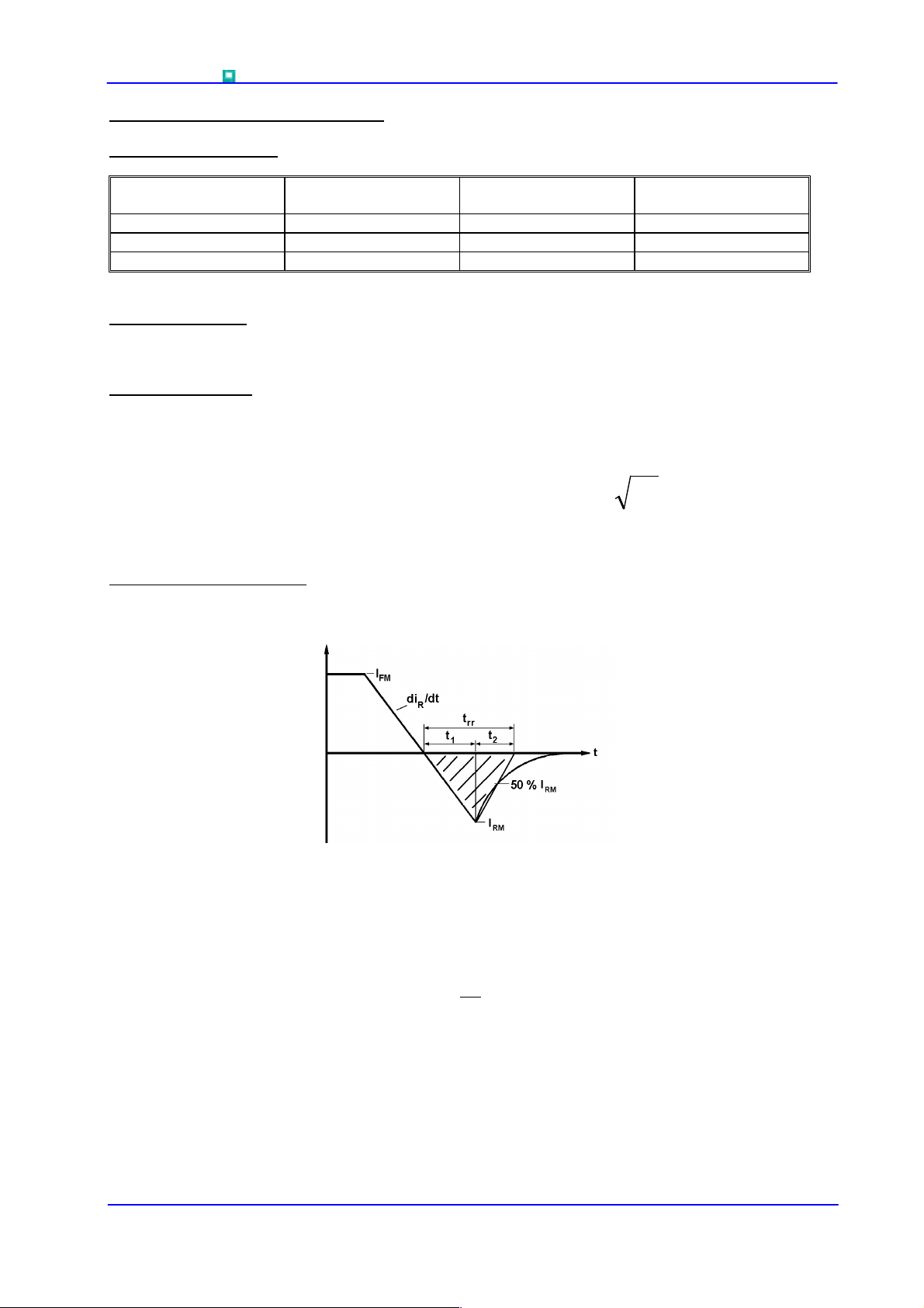
4.0 Reverse recovery ratings
(i) Qra is based on 50% Irm chord as shown in Fig.(a) below.
RRM
(V)
V
RSM
(V)
IDICIBAV ⋅+⋅+⋅+= )ln(
FFFF
V
dc
R
(V)
(ii) Qrr is based on a 150µs integration time.
s
µ
150
I.e.
(iii)
Data Sheet. Types M2408N#020 to M2408N#060 Issue 2 Page 3 of 11 July, 2004
=
FactorK =
dtiQ
.
rrrr
∫
0
t
1
t
2
 Loading...