

@)
WESTCODE
@)
SEMICONDUCTORS
Fast Recovery Stud-Base Diode Type PHN/PHR170
150
amperes average: up
to
1200 volts V
RRM
Technical
Publication
DFP170
Issue 1
February
1981
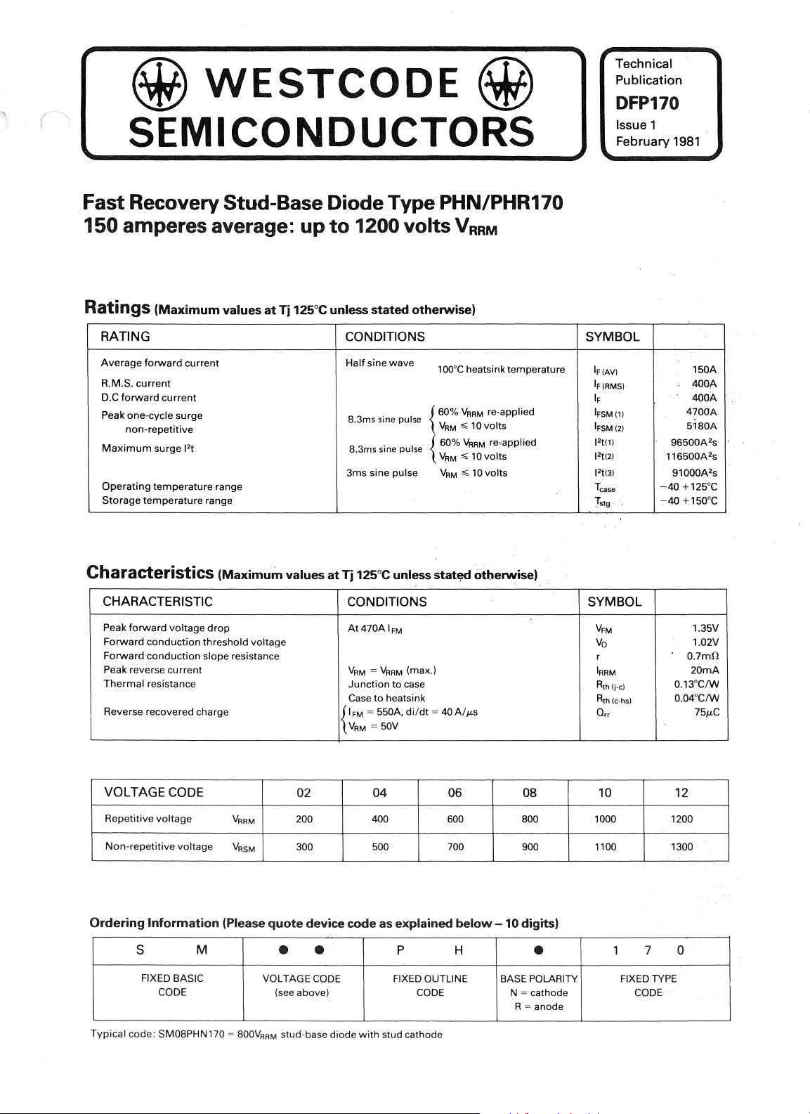
Ratings
(Maximum
values
at
Tj
125°C unless
stated
RATING CONDITIONS
Average
R.M.S.
D.C
Peak one-cycle surge
Maximum
Operating
Storage
Characteristics
forward
current
current
forward
current
non-repetitive
surge 12t
temperature
temperature
range
range
(Maximum
CHARACTERISTIC
Peak
forward
voltage
drop
Forward
Forward
Peak reverse
Thermal
Reverse recovered charge
conduction
conduction
current
resistance
threshold voltage
slope resistance
values
Half
sine
. { 60%
8.3ms
sme
8.3ms
sine
3ms sine pulse
at
Tj
125°C unless
CONDITIONS
At
470AIFM
VRM = VRRM
Junction
Case
to
tFM = 550A,di/dt
VRM
= 50V
otherwise)
wave
pulse
pulse
(max.)
to
case
heatsink
100°C
heatsink temperature
VARM
10
M';;
VARM
,;;
10
,;;
10
otberwise)
re-applied
I
vots
re-applied
volts
volts
VA
60%
{
VRM
VRM
Stat~
= 4OA/p,s
SYMBOL
IF
(AVI
IF
(RMSI
IF
IFSM(ll
IFSM(21
J2t(lI
J2t(21
12~(31
Tease
T
,
stg
SYMBOL
VFM
Va
r
IRRM
Rth(j.el
Rth(e.hsl
Q,.,
150A
4bOA
460A
4700A
5180A
96500Azs
116500A2s
91000A2
-40
+125°C
-40
+ 150°C
1.35V
1.02V
0.7mO
20mA
0.13°CIW
O.04°CIW
75p,C
s
VOLTAGE CODE
Repetitive
Non-repetitive
Ordering
voltage
Information
S
FIXED BASIC
CODE
Typical
code; SM08PHN 170 = 800V
voltage
M
VRRM
VRSM
(Please
02 04
200 400 600 800
300 500 700 900
quote
device code as explained
with
stud cathode
P
FIXED OUTLINE
• •
VOLTAGE
(see above)
stud-base
RRM
CODE
diode
06
below
H
CODE
08
-10
digits)
•
BASE POLARITY
N = cathode
= anode
R
10
1000 1200
1100 1300
1 7
FIXED TYPE
12
0
CODE
INTRODUCTION
1.
The
SM2-12PHN/R170
recovery
under
24mm
spring
housings
controlled
good'S'
factors. These devices
applications
switching
2. NOTES
(a)
Square
ON
wave
These ratings are given
rates
of
rise
(b)
Energy
for
the
enable
per
curves,
appropriate
maximum
These
dissipations
(c)
Junction
Single
pulse
for
all rating conditions.
Let: Ep be
T be
Rs
and
T
CASE
the
operating
f =
125-
diode
series comprises fast
all diffused silicon slices
pressure in stud base,
with
flexible leads. All these diodes have
top
reverse recovery characteristics
will
as 'free wheel' diodes in
find
transistor
circuits.
THE RATINGS
ratings
for
oftorward
pulse characteristics
when
operating frequencies and
to
be obtained.
temperature
junction
the
Energy
and pulse
the
appropriate junction
rise, in degrees Centigrade
be
the
steady-state thermal resistance
(junction
to
be
the
case temperature
frequency
T
-tCASE
leading edge linear
current
of
100
and 200AI fLS.
used in conjunction
junction
temperature rise,
rise
per
pulse
temperature rises are
per
pulse
for
width,
in Joules
a given
case)
may
be obtained
temperature
mounted
hat
with
with
those
given
current
from
where
t =
duration
pulse in microseconds
where
A = Area
pulse in microjoules
The
Energy
include
A x
to
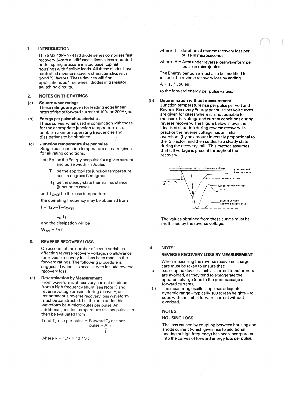
(b)
Determination
Junction
the
per
the
reverse recovery loss
6
10-
Joules
forward
energy
temperature
Reverse Recovery Energy
are
given
for
measure
the
cases
voltage
reverse recovery. The Figure
idealised situation
practice
overshoot
the'S'
during
that
the
reverse voltage has an initial
(by an
Factor) and then settles
the
recovery 'tail'. This
full
voltage
recovery.
-_
.....
commutating
di/dt
L
of
reverse recovery loss per
under
reverse loss
pulse
must
also be
per
pulse values.
without
measurement
rise
per
per
where
it
pulse per
pulse
is
not
and current conditions
below
during
reverse recovery. In
amount
inversely proportional
to
method
is present
throughout
....-.-
reverse
...-
typical
waveform
modified
by
adding
volt
per
volt
possible
curves
to
during
shows
the
a steady state
assumes
the
recovery
current
reverse
voltage
per
to
and
to
EpRe
and
the
dissipation
WAY
=
Epf
3.
REVERSE RECOVERY LOSS
On account
affecting
for
forward
suggested
reverse recovery voltage, no allowance
reverse recovery ioss has been
ratings. The
when
of
the
will
number
following
it
is necessary
recovery loss.
(a)
Determination
From
waveforms
from a high
reverse
frequency
voltage
by
Measurement
of
recovery current obtained
present
instantaneous reverse recovery loss
must
be constructed. Let
waveform
additional
then
Total
where
be A microjoules per pulse.
junction
be evaluated
TJ
rise
rt
= 1.77 x 10-
ternperature rise
from:
per
pulse = Forward
4
be
of
circuit variables
procedure is
shunt
(see Note
during
the
area
pulse
\,It
made
in the
to
include reverse
1)
and
recovery, an
waveform
under
this
An
per
pulse can
TJ
rise
+Arj
per
The
values obtained
multiplied
by
from
the
reverse voltage.
these curves
4. NOTE 1
REVERSE RECOVERY LOSS BY MEASUREMENT
When
care
(a) a.c.
are
apparent
measuring
must
coupled
avoided, as
charge (due
the reverse recovered charge
be taken
to
ensure that:
devices such as
they
tend
to
to
the
current
exaggerate the
prior
passage
fOf'\'Vard current).
(b)
The
measuring
dynamic
cope
with
oscilloscope has adequate
range -
the
typically
initial
100 screen heights -
forward
current
overload.
NOTE 2
HOUSING
The
anode
heating
into
lOSS
loss caused
cu
at
the
curves
by
coupling
rrent (which gives rise
high
frequency) has been incorporated
of
forward
between housing and
to
additional
energy loss
must
be
transformers
of
to
without
per
pUlse.

-
100
f'
10
~
~
"""
'"
I'-..
,I"
200A
1t,
I"-
'\
'\ri"~<'
'"
r--t-
-
1-+-.
r---t'~
0.1
N
I
I-
>£
,,::
u
Q)
"
:J
0-
0.01
~
0.01
pulse
Figure
1 Frequency v. pulse
II~~
T
&'lll-~
.,,,,
jA~
8000A
~~
\
0.1
width,
m.sees
Tease
200AIJLs
square
~<t:
~'?!
..
~
-It;
..
;'<q,,,
I,
'iT
'\
\[\
\
1\
width
85°C
wave
1\
100
~-200A
~ll
I
t---~
f::::
~~
10
55°C
Tease
200AIJLS
square
wave
I
,
ft.,
1\,['),
1\
i'f~
f\
~
..
,,~
\
'-\1
~~
~
I>rt-~
.,
.,
~~
1\
\
\"
v.
.,
111
\
n
pulse
~
m.secs
\
1"'-
\
1\
width
\
\
1'\
10
10
0.1
N
I
>£
,,::
u
Q)
"
:J
0-
0.01
~
0.01 0.1
Figure
\
1\
t\
f=j::::
~""'~
8000 A
II
10000 A
I
pulse
width,
2 Frequency
100
10
Q)
'"
~
0.1
.,;
'"
'S
a.
<;
a.
,.
E'
1!
" 0,01
figure
/'
Vv
./
/'
V
/'
0,01
pulse
width,
3 Energy
If/
71/
til!
1/
I/V
/
/
/
0.1
m,secs
per
r;p
~
?/.
it(!"/"j
;WI
;/J',-'-
:tV
-.-
r~
'#" ,(
',,/
~II
...
"J
",.<
'#-.-
Jj>"
v
~V
III
1]
~1125°C
/
200AIJLs
square
wave
Ililll
I I
pulse
v.
pulse
III
width
10
100
10000 A
-
~~
I
/v
VI
V
)/
10
/
1/1/
1/1,/
V
R
p
.,;
v
'"
."
E!
V
2
l'?
r-
c.
"
E
~
0.1
0.01
pulse
width,
Figure 4 Temperature
pulse
V
V
V
/
/
0,1
m.secs
width
7
~#y;
,<if'
~
df'~
,
~"17
{
<if'
~
~I
,0'''
1]
==
125°C
-200A/JLs
square
11t'111
rise
per
pulse v.
I
wave
111111
10
'S
§'
E
'S
"
E'
.,
l(l
0
g
a.
~
a.
>-
<:
'"
0.1
0,03
commutating
20
dUdt,
50 100
AIILS
200
Figure
5 Max, reverse energy
per
recovery volt
at
loss
Tj
125°C
per
pulse

100
,~
200A
~~
~f',
10
"-f---
,
I"
f\
0.1
F=
r--
N
J:
'"
~
c:
Q)
::l
C"
!
Figure 6 Frequency
6000A t
0.01
0.Q1
pulse
","
j.j~~
~~
,i"~
5000A
!
IT
0.1
width,
m.secs
Tease
100AIJ.Ls
square
,
il.r'l
'\
~~~
~
-Jb~
~
-i\,"1
"'11
~~
\
v.
pulse width
'\
\\
\
1\
85°C
wave
1\
10
100
3DOA
"-
~~
10
1\
1\
f\
0.1
N
~
I--
~
ai
::l
_
w
0.01
0.01
pulse
Figure 7 Frequency
1\
N~~
'I""l't
II
0.1
width,
m.secs
Tease
100AIJ.Ls
square
'</,
\;
1\1
f~~
N~
~
't:1
,,~
\
1:1
~~
~
~
~
\
i\
11
\
I
v.
pulse width
55°C
wave
'\
1\
1'\'\
1\
\
1\
[\
10
100
-.
10
~
'j
!)TIll
rill
/
1/
0.1
0.01
./
P'"
0.01
pulse
1/
V
/V
Xl
:;
.2.
~
~
~
>
2'
Q)
~
Figure 8 Energy per pulse
width,
I~
/
7
0.1
m.secs
;~vL:
~~
"V
~":/
~
~"I/
--r
'(fJ~
'#-~X
'
~v
~/'
IV~/
'#..~
~~
~~
V
III
Tj
= 125°C
100
AIJ.Ls
I
~quarewa
v.
pulse width
ve,
10
100
l==.'ooor7
~~"zS~
/V
//
/
10
1/
II
I
V
~
V
.~
i!!
V
~
Q)
c.
V
E
0.1
!
0.01
pulse
width,
Figure 9 Temperature
pulse
/
V
/
/
0.1
m.secs
width
~~
~
/
/
II
1j
100AIJ.Ls
squarew~
rise
per pulse
~
II/'
~y
~}
II
~
,(i!'
~
..
/
;j>"
<
~
,<f>"
II
I
II
~
125°C
v.
10
~
0.1
Q)
"0
., >
:;
~
i
~0.03
3l
·c
~
0.01
~
~
E
J!l
0.003
c:
V
o
'u
c:
."- 0.001
10
commutating
~~
20
~
r:::::-
dildt,
AI
50
ILS
~
100
200
'
....
""
.
....
,
....
Figure 10 Max. junction temperature
per
pulse
per recovery volt
lj
125°C
rise
at

100
200
A
~
~
300
A
r------I'--
I"--
10
r---
r---
--
----~~,~~~~
0.1
-f-'
N
=s~~"
-,
I
~
-'~
,;.
c:
"
1"'1
Q)
:J
C"
~
0.01
0.01 0.1
pulse
Figure
11
100
,
~-f
~~I
f'
I":
"
width,
Frequency v. pulse
"l)fk
,\~'?
Il'f..
rn'\:"
..
.,
\"
I
m.secs
~
1;.'1...
"
~
g'
1\
..
..
85°C
Tease
sine
wave
i
..
[\.
"
[\.\
1\
1\
1\
\
10
width
tl.t:7;:'"
rr(~~;;~
.
~.A
100
~
300
A!
I'
Tease
sine
' I I
t---.J,
I'--
f--
10
""""
~I\
-......
\
0.1
I
~
N
?i
c:
OJ
:J
r=~
==
-
f--
I 0.01
0.01
pulse
Figure 12 Frequency v. pulse
SOOA
1b
'f~,
•.
1-
1\
I,,{
r"~
1'\
N~"
~r"
1ij;
..
;:;;\.
\
.Y
i~~'
r\
~
..
~~~~
y~.,
1\
~I
0.1
width,
m.secs
wave
4;
1\
1\ \
K
width
55°C
,
I
I
1\
I"
10
20
V/I/
VV
/
VI?
/
/
/
/
0.1
m.secs
di/dt,
1/
~
'J';
.7-
',f"
f,f)"'{
,,'l
r~j;
~
.j?
#"
1/
lJ;fy
1%"
V
/
,#"
1)
/
= 125°C
11~lilne
~f~TI
--=====
~
50
100
A/p.s
10
po'
~
I---"
II>
I---"
OJ
:;
0.1
E
.Q.
ill-
:;
c.
~
>
~
OJ
m
Figure 13 Energy per pulse v. pulse
1l
E
o
:;
o
"
e
"
'f'
o~
oi
~
.c
'"
"
"0
Q)
Q;
>
o
"
~
0.01
0.01
1000
200
100
50
30
10
10
P'"
~
f-
V
pulse
width,
~
~
----
commutating
10
width
200
'000'
..,.
"".
,,,,.
MIN
(915%
AT400A
CQNFIOEHCEI
pulse
width,
m.secs
Figure 14 Temperature rise per pulse v.
Figure
pulse
15
width
Maximum
at
lj
125°C
recovered charge

1.1
"l"f-c------._-
..
_'.-
.. -
__ ' ..
-._'.-
...
"-rr-rr-_.-.-
1.0
t---t--+-I--+-++1-++-I./-' ....
0.9
t---1--+--+-++14-1+---+
0.8
t---t--IV--7'H-+-++++---+---+-t--++H-t-
f---t/r-
~
0.7L/
J!!
1/
(/)
0.6 M<-
__
10 20 50
recovered charge,
Figure 16
10000
3000
Minimum
v--t---+--+-+·+~
-.
+.
"-----"_L-Li-LLU
JLC
S factor
,/
_.-
..
-r-.--,---r-
7f
,L.
-11-.
__
---"_-L--'--'--L.LL.L
100 20
at
li
125°C
-+-+-+H++1
1
"""
I
-1--1-+++++1
1.0m.~~.
1G.13"CIW
0.1
~
P
oj
c:
"
co
0.Q1
.,
"
"-
.5
iii
E
Q;
0.001
-5
0.001
Figure 17
time,
0.Q1
seconds
Junction
0.1
to
case transient thermal impedance
:j!,
,
,I
i
l~
II
II
.
,
•
I
10
V
V
,/'
1000
/'
/
/
~
~
500
E
to
i
~
5 300
"
'E
~
.E
In
:::l
iil
c:
5
c:
~
.E
100
1.0
max.
Figure 18 Forward voltage characteristic
V
125"C
/
/
/
1.2
instantaneous forward voltage, volts
1.4
1.6 1.8
2.0
V
V
2.2 2.4
of
limit
V
diode
100.51
m.secs
duration
Figure 19 Max. non-repetitive surge current
initial
junction temperature
010.5
i.<1i
21.4
5
cycles at 50Hz
of
surge
125°C
l
:;;
"
i!
10
'"
~
dimensions in
mounting
thread
weight:
mm
torque: 27-24.5 Nm.
must
250 grams
(inches)
(2.77-2.5 kgf m)
not
be lubricated
at
In
the
interest
of
product
WESTCODE
improvement,
SEMICONDUCTORS
Westcode reserves
0-02 Fair Lawn Avenue, Fair Lawn,
Telephone (201)
.....
HAWKER
SIDDELEY
Westinghouse
791-3020
Brake
• Telex
and
New
Jersey
130389
Signal
the
Co_
right
to
07410
Ltd.
change
specifications
at
any
time
without
notice.
 Loading...