

Page 1

Date: 13th February 2015
Issue: 4
Application note for device mounting
instructions
Introduction
This document outlines the minimum mounting conditions for IXYS UK Westcode Ltd high
power press-pack diodes, thyristors, GTO’s, IGBT’s and pressure contacted modules.
Recommendations for interface properties
The interfaces to the device pole faces/baseplate (either heatsink or busbar) must conduct both
thermal and electrical energy from the device. It is important that these interfaces maintain a
stable contact throughout the lifetime of the equipment to ensure reliable operation of the
device. Both the surface geometry and finish are important factors to consider.
Surface roughness
The surface roughness is a measure of the microstructure of the surface and is expressed as a
R
value as per BS EN ISO 4287:1998+A1 2009. Prior to heatsink preparation a surface
a
roughness, R
Surface flatness
Flatness is a measure of the net variation of a surface defined by two parallel planes. A flatness
of 30µm is required for thyristors, diodes and GTO’s and 10µm for IGBT’s for all interface
surfaces within the clamping structure and clamp force range specified in the device data sheet.
Note 1: The flatness of an IGBT greater than that specified in the clamped condition may be
seen prior to the device being clamped. This is due to differential thermal expansion of the
housing components post manufacture and in no way reflects or impacts the device flatness
once it is clamped to the nominal force.
Note 2: The stack components must only deflect elastically. A flatness greater than the
maximum specified may result if plastic deformation of the contact surfaces (such as cooler
collapse) occurs under loading.
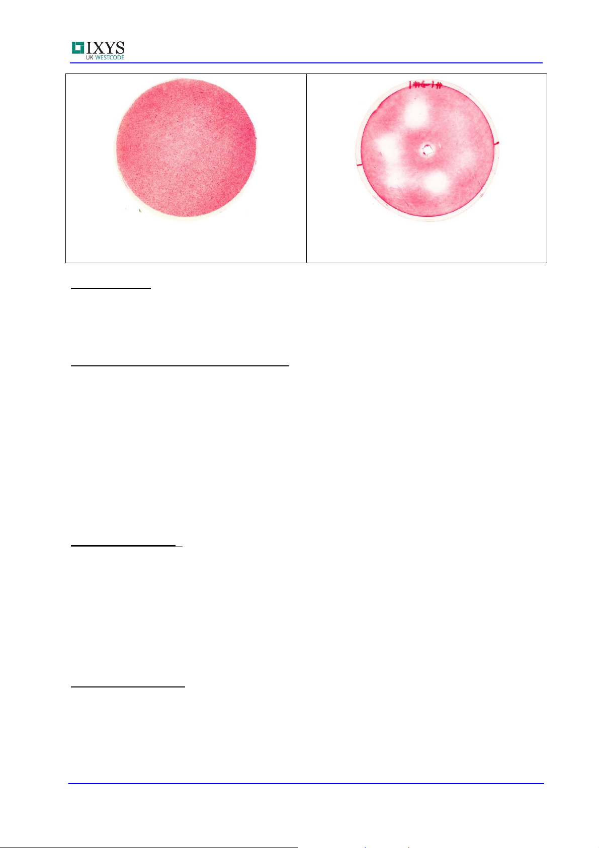
Westcode recommends the use of Fuji Prescale film; see
film product to confirm the pressure uniformity of the mechanical design of the assembly. The
film is manufactured in a number of different pressure ranges and should be inserted between
the device contact face and the cooler or heatsink. A good pressure distribution and a nonuniform pressure distribution are shown in figures 1 and 2 respectively.
≤1.6µm for all contact surfaces is recommended.
a
www.fujifilm-prescale.eu or a similar
Application Note Type: Mounting instructions Page 1 of 7 February, 2015
Page 2
Application Note 2008AN01 Issue 4
Figure 1: Example of good pressure
distribution
Figure 2: Example of poor pressure
distribution
Surface finish
In order to maintain a good electrical connection and avoid corrosion over time, Westcode
recommends that all non-aluminium contact surfaces be nickel-plated. Chemical plating is
preferable to electroplating in high reliability applications. Plating depth should be 4-6µm in
accordance with that applied to the device or module.
Surface preparation prior to assembly
All contact surfaces should be clean and dry prior to assembly. If necessary all non-plated
contact surfaces should be lightly abraded to remove oxide films with a rotary wire brush using
a suitable contact grease to form a slurry or alternatively polished using 3M Scotchbright™ or a
similar product. Note that the slurry produced by the abrasion should be left on the contact
surface until the device is ready to be mounted (to prevent re-oxidation). The contact surfaces
should then be cleaned using ethanol or similar solvent and a lint free cloth. Lint free gloves
should be worn when handling prepared parts. A very thin film of suitable mounting grease,
such as Jetlube SCX13 (Westcode part number XSGSCX13) should be applied to the device.
When the device has been clamped to full load a small bead approximately 0.1mm in diameter
should be squeezed out from between the contact surfaces.
Pictures of the surface preparation process are shown in appendix 1.
Mounting Force, F
M
The mounting force, FM is the recommended force to be applied for optimal device performance.
The data sheet ratings are not guaranteed if the mounting force is lower than that specified in
the data sheet. The thermal impedance and the on-state voltage drop will increase, and the
short circuit current rating will decrease when the force is reduced below the rated value.
Too high a mounting force could reduce the load cycling capability. The mounting force must be
uniformly applied across the whole area of the pole face or baseplate, this is particularly
important for press-pack IGBT’s. Variations in contact pressure of more than 10% across the
pole face or baseplate are not permitted.
Application support
A full range of clamps, coolers and other assembly parts are available from IXYS UK Westcode
Ltd. Please contact your local distributor, Area Sales Manager or the factory direct for more
information.
Application Note Type: Mounting instructions Page 2 of 7 February, 2015
Page 3
Application Note 2008AN01 Issue 4
Appendix 1: Press pack mounting instructions
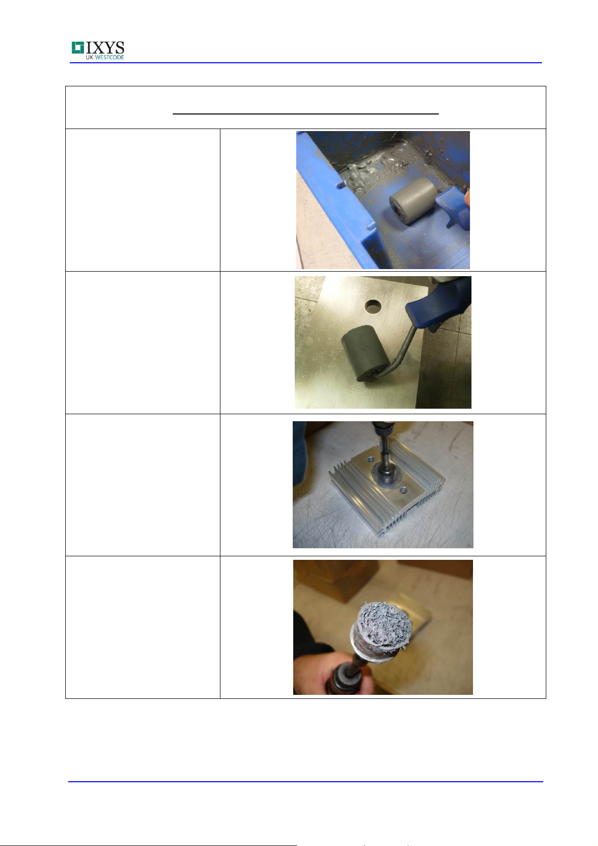
Load the roller with a small
amount of Jetlube SCX 13.
Apply the grease to the
heatsink close to the spirol
pin as shown.
An air operated rotary wire
brush is used to abrade the
paste onto the heatsink.
Note that the rotary wire
brush must be replaced
when the bristles are too
short.
Application Note Type: Mounting instructions Page 3 of 7 February, 2015
Page 4

Application Note 2008AN01 Issue 4
These bristles are of an
acceptable length.
Leave the heatsink slurried
with the thermal grease until
the device is ready to be
mounted.
When ready to mount the
devices remove the paste
with a lint free tissue as
shown.
Appendix 1 (continued)
The heatsink mounting
surface should appear lightly
abraded as shown.
Apply a small amount of
thermal grease to a roller as
shown.
Application Note Type: Mounting instructions Page 4 of 7 February, 2015
Page 5

Application Note 2008AN01 Issue 4
Apply a small amount of
thermal grease to the device
anode and cathode contact
surfaces.
Ensure that no debris or
hairs are left on the contact
surface.
The contact surface should
have a thin film of grease
applied to the surface as
shown.
Appendix 1 (continued)
Place the device onto the
heatsink.
Note that a small amount of
grease should be squeezed
out of the device/ heatsink
joint when the clamp is
tightened. Excessive grease
will cause a high volt drop
across the joint and affect
heat transfer.
The bead of grease should
be no more than 0.1mm.
Application Note Type: Mounting instructions Page 5 of 7 February, 2015
Page 6

Application Note 2008AN01 Issue 4
Heatsink after the device
was removed to show the
bead of thermal grease that
has been squeezed out of
the contact area when the
pressure was applied.
Close up of the device
mounting area after the
device was removed.
The bead of grease is no
more than 0.1mm in
diameter.
Appendix 1 (continued)
Appendix 2: Pressure contacted module mounting instructions
Apply the thermal grease to
the baseplate using the
roller.
Ensure that no debris or
hairs are left on the
baseplate.
The baseplate should have a
thin film of grease applied to
the surface as shown.
Application Note Type: Mounting instructions Page 6 of 7 February, 2015
Page 7

Application Note 2008AN01 Issue 4
Mount the module to the
heatsink
Torque the screws to the
correct torque wrench setting
as detailed in the datasheet.
Ensure that the screws are
tightened evenly.
Appendix 2 (continued)
Blank
Application Note Type: Mounting instructions Page 7 of 7 February, 2015
 Loading...