

Page 1
®
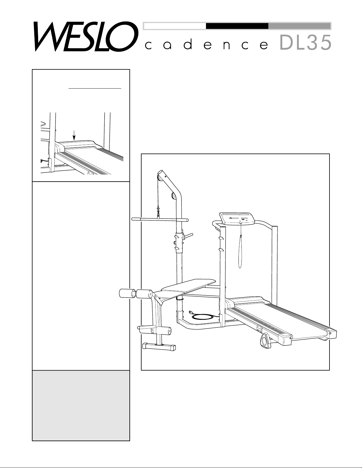
USER'S MANUAL
CAUTION
Read all precautions and
instructions in this manual
before using this equipment.
Keep this manual for future
reference.
Model No. WLTL46080
Serial No.
QUESTIONS?
As a manufacturer, we are
committed to providing complete customer satisfaction. If
you have questions, or if
there are missing parts, we
will guarantee complete satisfaction through direct assistance from our factory.
TO AVOID UNNECESSARY
DELAYS, PLEASE CALL DIRECT TO OUR TOLL-FREE
CUSTOMER HOT LINE.
The trained technicians on
our customer hot line will
provide immediate assistance, free of charge to you.
CUSTOMER HOT LINE:
1-800-999-3756
Mon.–Fri., 6 a.m.–6 p.m. MST
Write the serial number in the
space above for future reference.
Patent Pending
Serial
Number
Decal
Page 2

2
Table of Contents
IMPORTANT PRECAUTIONS . . . . . . . . . . . . . . . . . . . . . . . . . . . . . . . . . . . . . . . . . . . . . . . . . . . . . . . . . . . . . . . . .3
BEFORE YOU BEGIN . . . . . . . . . . . . . . . . . . . . . . . . . . . . . . . . . . . . . . . . . . . . . . . . . . . . . . . . . . . . . . . . . . . . . . .5
PART IDENTIFICATION CHART . . . . . . . . . . . . . . . . . . . . . . . . . . . . . . . . . . . . . . . . . . . . . . . . . . . . . . . . . . . . . . .6
ASSEMBLY . . . . . . . . . . . . . . . . . . . . . . . . . . . . . . . . . . . . . . . . . . . . . . . . . . . . . . . . . . . . . . . . . . . . . . . . . . . . . . .7
HOW TO OPERATE THE TREADMILL . . . . . . . . . . . . . . . . . . . . . . . . . . . . . . . . . . . . . . . . . . . . . . . . . . . . . . . . .13
HOW TO EXERCISE ON THE TREADMILL . . . . . . . . . . . . . . . . . . . . . . . . . . . . . . . . . . . . . . . . . . . . . . . . . . . . .17
HOW TO OPERATE THE WEIGHT BENCH . . . . . . . . . . . . . . . . . . . . . . . . . . . . . . . . . . . . . . . . . . . . . . . . . . . . .18
HOW TO EXERCISE ON THE WEIGHT BENCH . . . . . . . . . . . . . . . . . . . . . . . . . . . . . . . . . . . . . . . . . . . . . . . . .20
TROUBLE-SHOOTING AND MAINTENANCE . . . . . . . . . . . . . . . . . . . . . . . . . . . . . . . . . . . . . . . . . . . . . . . . . . .21
PART LIST . . . . . . . . . . . . . . . . . . . . . . . . . . . . . . . . . . . . . . . . . . . . . . . . . . . . . . . . . . . . . . . . . . . . . . . . . . . . . . .23
ORDERING REPLACEMENT PARTS . . . . . . . . . . . . . . . . . . . . . . . . . . . . . . . . . . . . . . . . . . . . . . . . . .Back Cover
LIMITED WARRANTY . . . . . . . . . . . . . . . . . . . . . . . . . . . . . . . . . . . . . . . . . . . . . . . . . . . . . . . . . . . . . . .Back Cover
Note: An Exploded Drawing is attached in the center of this manual. Save the Exploded Drawing for future reference.
®
Page 3

3
1. It is the responsibility of the owner to
ensure that all users of the CADENCE DL35
are adequately informed of all warnings and
precautions.
2. Use the CADENCE DL35 only as described
in this manual.
3. Place the CADENCE DL35 on a level surface,
with eight feet of clearance behind it. Do not
place it on a surface that blocks any air
openings. To protect the floor or carpet from
damage, place a mat under the CADENCE
DL35.
4. Keep the CADENCE DL35 indoors, away
from moisture and dust. Do not put it in a
garage or covered patio, or near water.
5. Do not operate the treadmill where aerosol
products are used or where oxygen is being
administered.
6. Keep children under the age of 12 and pets
away from the CADENCE DL35 at all times.
7. The CADENCE DL35 should be used only by
persons weighing 250 pounds or less.
8. The CADENCE DL35 should never be used
by more than one person at a time.
9. Wear appropriate exercise clothing when
using the CADENCE DL35. Do not wear
loose clothing that could become caught in
the treadmill. Athletic support clothes are
recommended for both men and women.
10. Always wear athletic shoes when using the
CADENCE DL35. Never use it with bare feet,
wearing only stockings, or in sandals.
11. Inspect and tighten all parts of the
CADENCE DL35 regularly.
12. To connect the power cord (see page 13),
plug the power cord into a surge suppressor
(not included) and plug the surge suppressor into a grounded circuit capable of carry-
ing 15 or more amps. No other appliance
should be on the same circuit. Do not use an
extension cord.
13. Use only a UL-listed surge suppressor, rated
at 15 amps, with a 14-gauge cord of five feet
or less in length. Do not use an extension
cord.
14. Keep the power cord and surge suppressor
away from heated surfaces.
15. Never move the walking belt while the power
is turned off. Do not operate the treadmill if
the power cord or plug is damaged, or if the
treadmill is not working properly. (See
Before You Begin on page 5 if the treadmill
is not working properly.)
16. Never start the treadmill while you are
standing on the walking belt. Always hold
the handrail while using the treadmill.
17. The treadmill is capable of high speeds.
Adjust the speed in small increments to
avoid sudden jumps in speed.
18. To reduce the possibility of the treadmill
overheating, do not operate the treadmill
continuously for longer than one hour.
19. Never leave the treadmill unattended while it
is running. Always remove the key when the
treadmill is not in use.
20. You must be able to safely lift 50 pounds (23
kg) in order to raise or lower the treadmill.
21. Never insert any object into any opening.
22. Always unplug the power cord before performing the maintenance and adjustment
procedures described in this manual. Never
remove the motor hood unless instructed to
do so by an authorized service representative. Servicing other than the procedures in
this manual should be performed only by an
authorized service representative.
WARNING:To reduce the risk of burns, fire, electric shock, or injury to persons, read the
following important precautions and information before operating the WESLO®CADENCE DL35.
Important Precautions
Page 4
4
WARNING:Before beginning this or any exercise program, consult your physician. This
is especially important for persons over the age of 35 or persons with pre-existing health problems.
Read all instructions before using. ICON assumes no responsibility for personal injury or property
damage sustained by or through the use of this product.
SAVE THESE INSTRUCTIONS
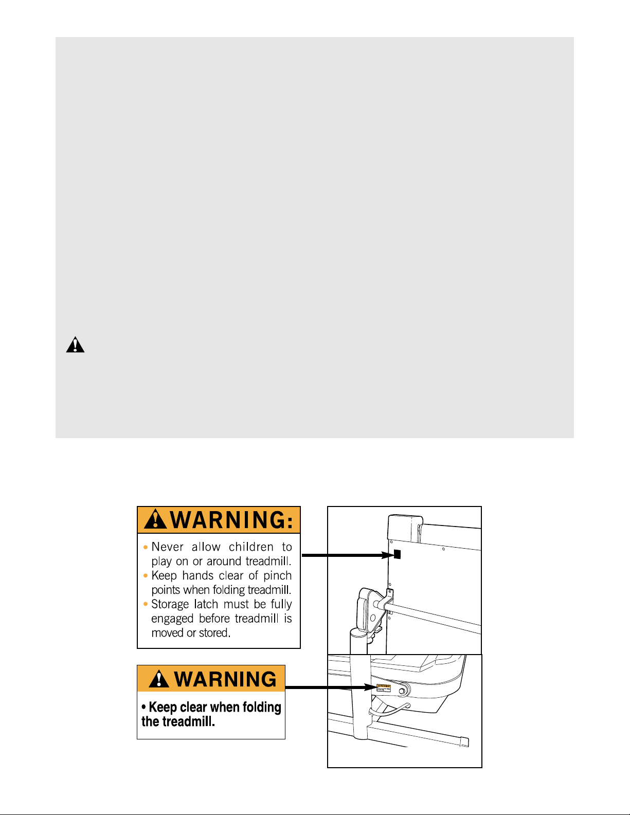
The decals shown below have been placed in the indicated locations on the treadmill. If a decal is missing, or if it is not legible, please call our Customer Service Department toll-free at 1-800-999-3756 to order
a free replacement decal. Apply the decal in the location shown.
23.The pulse sensor is not a medical device.
Various factors, including the user's movement, may affect the accuracy of heart rate
readings. The pulse sensor is intended only
as an exercise aid in determining heart rate
trends in general.
24. When using a barbell (not included), always
make sure that there is an equal amount of
weight on each side of the barbell.
25. Do not use a barbell that is longer than five
feet with the weight bench.
26. When using the backrest in the inclined posi-
tion, make sure that the support rod is fully
inserted into the lat tower and the upright,
and that the support rod is turned to the
locked position (see page 19).
27. Always perform bench press exercises with a
partner. Your partner should stand behind
you to catch the barbell if you cannot complete a repetition.
28. The weight bench does not include weights.
The weight bench is designed to support a
maximum of 360 pounds, including the user,
a weight bar and weights. Do not place more
that 110 pounds, including a weight bar and
weights, on the weight rests. Do not place
more that 50 pounds on the leg lever. Do not
place more that 30 pounds on the weight carriage on the lat tower.
29. If you feel pain or dizziness at any time while
exercising, stop immediately and begin cooling down.
30. The CADENCE DL35 is intended for in-home
use only. Do not use the CADENCE DL35 in
any commercial, rental, or institutional setting.
One decal on each side
Page 5
5
Congratulations for purchasing the revolutionary
WESLO®CADENCE DL35 treadmill. The CADENCE
DL35 offers both aerobic exercise and strength training
exercise to help you achieve total fitness in the convenience and privacy of your home. And when you’re not
exercising, the CADENCE DL35 can be folded up,
taking a fraction of the space needed for both a
treadmill and a weight bench.
For your benefit, read this manual carefully before
using the CADENCE DL35. If you have additional
questions, please call our Customer Service
Department toll-free at 1-800-999-3756, Monday
through Friday, 6 a.m. until 6 p.m. Mountain Time (excluding holidays). Please note the product model number and serial number before calling. The model number is WLTL46080. The serial number can be found on
a decal attached to the CADENCE DL35 (see the front
cover of this manual for the location of the decal).
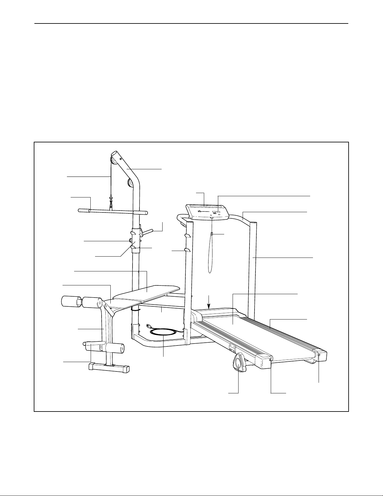
Before reading further, please familiarize yourself with
the parts that are labeled in the drawing below.
Before You Begin
Handrail
Console
Key/
Clip
Cable
Lat Bar
Circuit
Breaker
Walking Belt
Foot Rail
Power
Cord
Rear Roller
Adjustment Bolts
Towel Rack
Incline Leg
Seat
Backrest
Carriage Pin
Weight Carriage
Leg Lever
Weight
Tube
Weight
Tube
Weight
Rests
Support
Rod
Lat Tower
Upright
Page 6
6
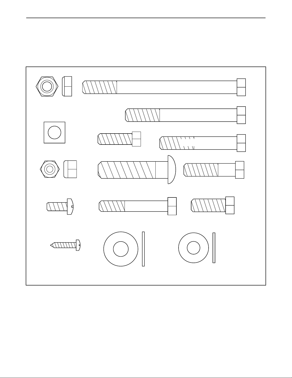
Part Identification Chart
This chart is provided to help you identify the small
parts used in assembly. The number in parenthesis
below each part refers to the key number of the part,
from the Part List on page 23.
Important: Some parts may have been pre-assembled for shipping purposes. If you cannot find a
part in the parts bag(s), check to see if it has been
pre-assembled.
3/8" Jam Nut (11)
Square Nut (30)
Bench Pivot Bolt (41)
3/8" x 4 1/2" Pulley Bolt (44)
3/8" x 3 1/4" Bolt (32)
3/8" x 2 1/4" Bolt (10)
5/16" Nylon Locknut (15)
1/4 x 3/4” Screw (3)
Catch Screw (126)
1/2" x 2" Carriage Bolt (22)
5/16" x 2" Bolt (19)
3/8" Washer (31)
3/8" x 1 1/2" Pulley Bolt (46)
3/8" x 1" Lat Bolt (141)
5/16" Washer (102)
Page 7
7
Assembly
Everything in this manual is designed to ensure
that the CADENCE DL35 can be assembled successfully by anyone. However, it is important to
recognize that the CADENCE DL35 contains
many parts and that the assembly process will
take time. Most people find that by setting aside
plenty of time and by deciding to make the task
enjoyable, assembly will go more smoothly.
Before beginning, make sure that you understand the following important points:
• Assembly requires two people.
• Place all parts in a cleared area and remove the
packing materials. Do not dispose of the packing
materials until assembly is completed.
• Tighten all parts as you assemble them, unless
instructed to do otherwise.
• For help identifying small parts, refer to the Part
Identification Chart on page 6.
• During assembly, make sure that all parts are oriented as shown in the drawings.
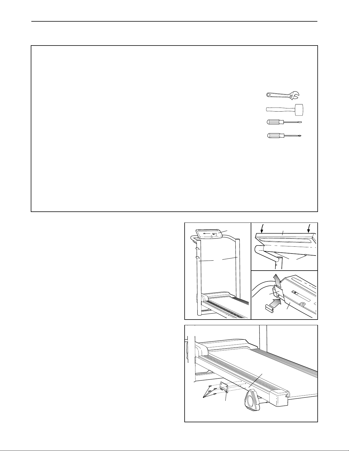
The following tools (not included) are required
for assembly:
• Two (2) adjustable wrenches
• One (1) rubber mallet
• One (1) standard screwdriver
• One (1) phillips screwdriver
• Lubricant, such as grease or petroleum jelly,
and soapy water.
Assembly will be more convenient if you have the
following tools: A socket set, a set of open-end or
closed-end wrenches, or a set of ratchet wrenches.
1. With the help of a second person, raise the Uprights
(70) to the position shown in drawing 1. Next, pivot
the Console (51) to the position shown in drawings
1 and 1a. Tighten the two Console Bolts (56).
The Console (51) requires two “AA” batteries (not
included). Alkaline batteries are recommended.
Refer to drawing 1b. Slide the Battery Cover (52)
upward and remove it. Insert two “AA” batteries into
the Console (51), making sure that the negative
ends of the batteries (marked “–”) are touching the
springs in the Console. Reattach the Battery Cover.
2. Attach the the Catch (124) to the left side of the
Frame (123) with four Catch Screws (126). Make
sure that the Catch is turned as shown. Note: It
may be necessary to remove the Catch Screws
from the left side of the Frame before beginning this
step.
1
1a
1b
70
51
51
51
126
124
123
56
52
2
Page 8
8
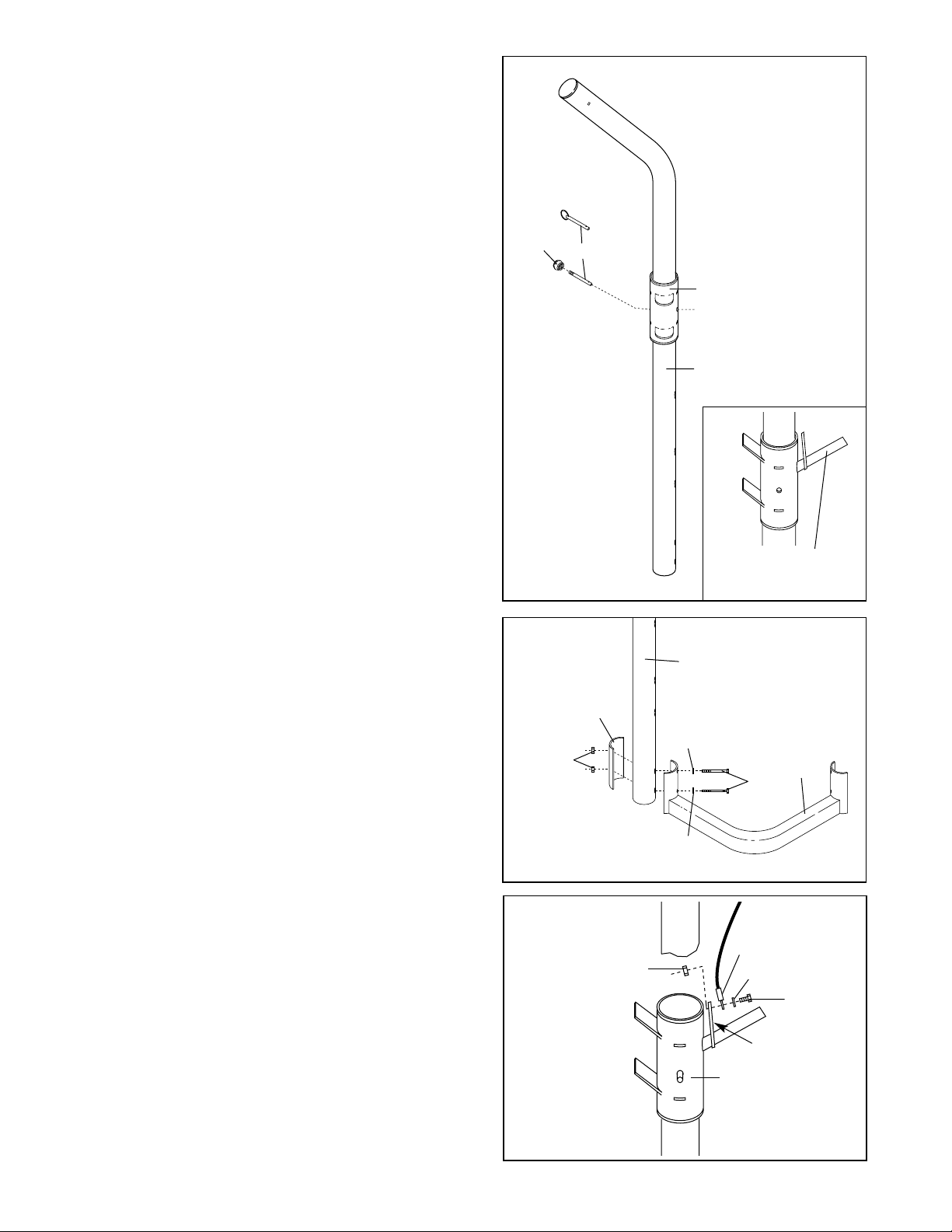
3. You have one of two types of Carriage Pins (38). If
you have type 2 (refer to the drawing), make sure
the Carriage Pin Knob (39) is attached to the
Carriage Pin (38).
Slide the Weight Carriage (23) onto the Lat Tower
(34). Make sure that the Weight Carriage is
turned as shown in the inset drawing. Slide the
Weight Carriage to the position shown and insert
the Carriage Pin (38) through the Weight Carriage
and the Lat Tower.
4. Hold the Lat Tower (34) in the position shown. Make
sure that the Lat Tower is turned as shown on page 5.
Attach the Base Plate (27) and the Corner Base
(33) to the Lat Tower (34) with two 3/8” x 3 1/4”
Bolts (32), two 3/8” Washers (31), and two 3/8” Jam
Nuts (11).
Lay the Lat Tower (34) down on the floor so that
it cannot be tipped over. The assembly of the
Lat Tower will be completed in step 17.
38
Type 2
Type 1
39
34
23
3
4
11
27
33
34
32
31
31
5. Identify the indicated end of the Lat Cable (40).
Attach the Lat Cable to the tab on the Weight
Carriage (23) with a 3/8” x 1” Lat Bolt (141), a 3/8”
Washer (31), and a 3/8” Jam Nut (11). Note: Do
not fully tighten the Jam Nut.
5
141
31
40
11
Tab
23
Weight Tube
must angle upward
Page 9

9
6. Lay the Lat Cable (40) over a Pulley (42). Slide the
Cable Trap (47) and Pulley onto a 3/8” x 1 1/2”
Pulley Bolt (46). Next, insert a Square Nut (30) into
the bracket on the Lat Tower (34) and insert a
screwdriver up into the bracket to hold the Square
Nut in place. Insert the 3/8” x 1 1/2” Pulley Bolt (46)
into the bracket and tighten it into the Square Nut.
Make sure that the Cable Trap (47) is turned to
the position shown, and that the Pulley (42)
turns freely.
7. Lay the Lat Cable (40) over another Pulley (42).
Attach the Pulley to the Lat Tower (34) with a 3/8” x
4 1/2” Pulley Bolt (44), a 3/8” Washer (31), a Pulley
Spacer (48), and a 3/8” Jam Nut (11).
Make sure that the Lat Cable (40) is between the
Pulley (42) and the welded pin, and that the
Pulley turns freely.
7
34
44
31
42
48
40
Pin
11
6
40
42
30
Bracket
34
46
47
8. Press a Stabilizer Cap (81) onto each end of the
Bench Stabilizer (21).
Attach the Bench Stabilizer (21) to the Bench Frame
(5) with two 1/2” x 2” Carriage Bolts (22) and two
5/16” Nylon Locknuts (15).
9. Attach the Weight Tube (17) to the Leg Lever (14)
with a 5/16” x 2” Bolt (19) and a 5/16” Nylon Locknut
(15).
Press a 1” Inner Cap (16) into the indicated end of
the Weight Tube (17). Press the 1” Outer Cap (18)
onto the other end of the Weight Tube. Slide the
Weight Bushing (74) onto the Weight Tube.
Press a Frame Cap (7) into each end of the Leg
Lever (14).
9
81
81
21
15
5
22
74
16
17
15
19
18
14
7
7
8
Page 10

10
11. Tap two 3/4” Inner Caps (12) into each Pad Tube
(20).
Insert the Pad Tubes (20) through the holes in the
Leg Lever (14). Center the Pad Tubes and slide two
Foam Pads (12) onto each Pad Tube.
10. Lubricate the 3/8” x 2 1/4” Bolt (10). Attach the Leg
Lever (14) to the Bench Frame (5) with the Bolt and
a 3/8” Jam Nut (11). Do not overtighten the Jam
Nut. The Leg Lever must pivot freely.
10
14
5
10
11
11
14
13
12
20
13
12
12. Attach a Backrest Bracket (2) to the Backrest (1)
with two 1/4” x 3/4” Screws (3). Make sure that the
Backrest Bracket is oriented as shown. Do not
tighten the Screws yet.
13. Refer to drawing 13a. Hold the Backrest (1) in a
vertical position as shown and slide the end of the
attached Backrest Bracket (2) onto the welded rod
on the Bench Frame (5). Hold the other Backrest
Bracket (2) at an angle as shown and slide it onto
the rod.
Refer to drawing 13b. Attach the Backrest Bracket
(2) to the Backrest (1) with two 1/4” x 3/4” Screws
(3). Note: The Screw nearest the rod should be
attached first.
Fully tighten all four 1/4” x 3/4” Screws (3) used
in steps 12 and 13.
13a
1
12
1
3
3
2
1
3
2
5
Rod
Rod
3
2
2
13b
Page 11

11
14. Attach the Seat (9) to the bracket on the Bench
Frame (5) with two 1/4” x 3/4” Screws (3).
15. Press a Frame Cap (7), into the Bench Frame (5).
Insert the Bench Pivot Rod (8) through the Bench
Frame (5) as shown. Center the Bench Pivot Rod
and slide a Bench Spacer (4) onto each end of it.
15
4
8
5
7
4
14
9
3
5
16. Press a 3/4” Inner Cap (12) into each end of the
Support Rod (25).
16
12
12
25
Page 12

12
17. Insert the left end of the Bench Pivot Rod (8) into
the indicated hole in the Lat Tower (34). Loosely
thread a Bench Pivot Bolt (41) with a 5/16” Washer
(102) into the end of the Bench Pivot Rod.
Next, insert the right end of the Bench Pivot Rod (8)
into the Upright (70) and slide the Corner Base (33)
against the lower end of the Upright. Loosely thread
a Bench Pivot Bolt (41) with a 5/16” Washer (102)
into the end of the Bench Pivot Rod.
Loosely attach the Corner Base (33) to the Upright
(70) with two 3/8” x 3 1/4” Bolts (32), two 3/8”
Washers (31), and two 3/8” Jam Nuts (11).
20. Make sure that all parts are properly tightened before you use the CADENCE DL35. If desired, attach
the included allen wrench to the treadmill frame with the plastic adhesive clip.
17
34
32
31
31
11
33
8
102
41
102
70
41
19. Make sure that there are Handgrips (35) on the
ends of the Lat Bar (36).
Attach the Lat Bar (36) to the Lat Cable (40) with a
Cable Clip (37).
19
36
37
40
35
35
18. Raise the Bench Frame (5) to the position shown
and hold it in place. Insert the Support Rod (25)
through the indicated holes in the Lat Tower (34),
the Bench Frame (5), and the Upright (70). Rotate
the Support Rod to the locked position, with the
hook clipped onto the Lat Tower as shown in the
inset drawing.
Refer to step 17. Tighten all parts assembled in
step 17.
18
5
34
25
70
Hook
Page 13

13
How to Operate the Treadmill
THE PERFORMANT LUBETMWALKING BELT
Your treadmill features a walking belt coated with
PERFORMANT LUBE
TM
, a high-performance lubricant.
Important: Never apply silicone spray or other substances to the walking belt or the walking platform.
They will deteriorate the walking belt and cause excessive wear.
HOW TO PLUG IN THE POWER CORD
Your treadmill, like any other type of sophisticated
electronic equipment, can be seriously damaged by
sudden voltage changes in your home’s power.
Voltage surges, spikes, and noise interference can result from weather conditions or from other appliances
being turned on or off.
To decrease the possibility of your treadmill being damaged,
always use a surge
suppressor (not
included) with your
treadmill.
Surge suppressors are
sold at most hardware
stores and department
stores. Use only a ULlisted surge suppressor,
rated at 15 amps, with a
14-gauge cord of five
feet or less in length.
This product must be
grounded. If it should
malfunction or break
down, grounding provides a path of least resistance for electric current to reduce the risk of
electric shock. This product is equipped with a cord
having an equipment-grounding conductor and a
grounding plug. Plug the power cord into a surge
suppressor, and plug the surge suppressor into an
appropriate outlet that is properly installed and
grounded in accordance with all local codes and
ordinances.
This product is for use on a nominal 120-volt circuit,
and has a grounding plug that looks like the plug illustrated in drawing 1 below. A temporary adapter that
looks like the adapter illustrated in drawing 2 may be
used to connect the surge suppressor to a 2-pole
receptacle as shown in drawing 2 if a properly
grounded outlet is not available.
The temporary adapter should be used only until a
properly grounded outlet (drawing 1) can be installed
by a qualified electrician.
The green-colored rigid ear, lug, or the like extending
from the adapter must be connected to a permanent
ground such as a properly grounded outlet box cover.
Whenever the adapter is used it must be held in place
by a metal screw. Some 2-pole receptacle outlet box
covers are not grounded. Contact a qualified electrician to determine if the outlet box cover is
grounded before using an adapter.
DANGER:Improper connection
of the equipment-grounding conductor can
result in an increased risk of electric shock.
Check with a qualified electrician or serviceman if you are in doubt as to whether the
product is properly grounded. Do not modify
the plug provided with the product—if it will
not fit the outlet, have a proper outlet installed by a qualified electrician.
1
2
Grounded Outlet Box
Grounded Outlet Box
Grounding Plug
Treadmill Power Cord
Grounding Plug
Grounding Plug
Grounding Pin
Surge Suppressor
Grounding Pin
Grounding Pin
Adapter
Lug
Metal Screw
Grounded Outlet
Page 14

14
HOW TO LOWER THE TREADMILL FOR USE
CAUTION: You must be able to safely lift 50
pounds (23 kg) in order to lower the treadmill.
To lower the
treadmill, hold the
upper end of the
treadmill with your
right hand as
shown. Using
your left hand,
slide the storage
latch to the left.
Pivot the treadmill
down until all
parts are past the
storage latch.
Note: It may be
necessary to turn the incline leg in order to lower the
treadmill.
Next, hold the treadmill firmly with both hands and
lower the treadmill to the floor. To decrease the pos-
sibility of injury, bend your legs and keep your
back straight.
HOW TO FOLD THE TREADMILL FOR STORAGE
Before folding the treadmill, unplug the power
cord. CAUTION: You must be able to safely lift 50
pounds (23 kg) in order to raise the treadmill.
To raise the treadmill, hold the treadmill with your
hands in the locations shown below. To decrease the
possibility of injury, bend your legs and keep your
back straight. As you raise the treadmill, make
sure to lift with your legs rather than your back.
Raise the treadmill about halfway to the vertical position.
Next, move your
right hand to the
position shown,
and hold the
treadmill firmly.
Using your left
hand, slide the
storage latch to
the left. Raise the
treadmill until the
storage latch
locks over the
catch. Make sure
that the latch
closes fully over the catch.
To protect the floor or carpet from damage, place a
mat under the treadmill. Keep the treadmill out of
direct sunlight. Do not leave the treadmill in the
storage position in temperatures above 85°
Fahrenheit.
Latch
Incline
Leg
Latch
Incline
Leg
Page 15

STEP BY STEP CONSOLE OPERATION
Make sure that batteries are installed in the console.
(See assembly step 1 on page 7.) Next, make sure
that the power cord is properly plugged in. (See How
to Plug in the Power Cord on page 13). Step onto the
foot rails of the treadmill. Find the clip attached to the
key (see the drawing above), and slide the clip onto
your waistband. Follow the steps on pages 15 and 16
to operate the console.
Insert the key fully into the power switch.
Note: The two displays will not appear when the key
is first inserted.
Press the ON/OFF button.
The two displays
will appear. Note: If
batteries were just
installed, the displays will
already appear.
Reset the speed control and start the walking
belt.
Slide the speed
control all of the
way to the left, to
the "SPEED
RESET" position.
Next, slide the control to the right until
the walking belt begins to move at slow speed.
Carefully step onto the walking belt and begin
walking. Change the speed of the walking belt as
desired by sliding the speed control. Note: To stop
the walking belt, slide the speed control to the
"SPEED RESET" position.
3
2
1
15
DIAGRAM OF THE CONSOLE
Key
Speed Control
Pulse Sensor
Monitor Display
Pulse Display
Clip
Note: If there is a thin sheet of clear
plastic on the console, remove it.
Key
CAUTION:Before operating the con-
sole, read the following important precautions.
• Do not stand on the walking belt when turning
on the power.
• Always wear the clip while operating the treadmill. When the key is removed from the console, the power will shut off.
• After the speed control is moved, there will be
a pause before the walking belt begins to move.
• Adjust the speed in small increments until you
are familiar with the treadmill.
• The training zones marked above the speed
control are guidelines only. Read How to
Exercise on the Treadmill on page 17 to determine the proper exercise level.
• To reduce the risk of electric shock, keep the
console dry. Avoid spilling liquid on the console and use only a sealed water bottle.
Page 16

Press the MODE button to select the desired
monitor mode.
The monitor offers five different modes to provide
instant exercise feedback:
• SPEED—displays
your speed, in
miles per hour.
• TIME—displays
the elapsed time.
• DISTANCE—displays the distance
that you have
walked or run, in miles.
• CALORIES—displays the approximate number of
Calories you have burned. Note: The actual number of Calories you have burned may differ
slightly from the number displayed if the speed or
incline is near the lowest or highest setting.
• SCAN—displays the SPEED, TIME, DISTANCE,
and CALORIES modes, for five seconds each, in
a repeating cycle.
When the power is turned on, the SCAN mode will
automatically be selected. One mode indicator
(see the drawing above), will appear by the word
SCAN, and a second mode indicator will show
which mode is currently displayed.
If desired, the SPEED, TIME, DISTANCE or
CALORIES mode can be displayed continuously.
Press the MODE button repeatedly until the mode
indicator bythe word SCANdisappears,and a mode
indicator appears by the name of the desired mode.
Note: The monitor displays can be reset by pressing the ON/OFF button twice.
Measure your pulse, if desired.
To use the pulse sensor, stand on the foot rails
and place your
thumb on the
pulse sensor as
shown. The pulse
sensor is pressure-activated—
fully press it down.
Do not press too
hard, or the circulation in your
thumb will be restricted, and your pulse will not
be detected. Next, slightly raise your thumb until
the heart-shaped indicator in the pulse display
flashes steadily. Hold your thumb at this level.
After 5 to 10 seconds, your pulse will be displayed.
Hold your thumb on the sensor for another 15 seconds for the most accurate reading.
If the displayed pulse appears to be too high or too
low, or if your pulse is not displayed, lift your thumb
off the sensor and allow the display to reset. Press
down again on the sensor as described above.
Make sure that your thumb is positioned as shown,
and that you are applying the proper amount of
pressure. Try the sensor several times until you
become familiar with it. Always stand still while
measuring your pulse.
When you are finished, stop the walking belt
and remove the key.
Step onto the foot rails, slide the speed control to
the “SPEED RESET” position, and remove the
key. Store the key in a secure location.
Press the ON/OFF button.
To turn off the displays, press the ON/OFF button.
Note: If the walking belt is stopped and the console
buttons are not pressed for 3 to 6 minutes, the displays will turn off automatically.
HOW TO CHANGE THE INCLINE OF THE TREADMILL
To vary the intensity of your exercise, the incline of the
treadmill can be changed. There are three different incline levels. Before changing the incline, remove the
key and unplug the power cord.
To change the incline
of the treadmill, first
hold the rear roller
endcap with one hand
and raise the back of
the treadmill a few
inches. Using your
other hand, rotate the
incline leg to one of
the three incline positions. The inset drawing at the right shows
the incline leg rotated
to the “max fat burn”
position. Lower the treadmill, making sure that the incline leg is resting flat on the floor.
7
6
5
4
16
Pulse Sensor
Mode
Indicators
Incline
Leg
Page 17

17
How to Exercise on the Treadmill
EXERCISE INTENSITY
Whether your goal is to burn fat or to strengthen your
cardiovascular system, the key to achieving the
desired results is to exercise with the proper intensity.
The proper intensity level can be found by using your
heart rate as a guide. The chart below shows recommended heart rates for fat burning and aerobic exercise.
To find the proper heart rate for you, first find your age
on the left side of the chart (ages are rounded off to
the nearest ten years). Next, find the three numbers to
the right of your age. The three numbers are your
“training zone.” The lower two numbers are recommended heart rates for fat burning; the higher number
is the recommended heart rate for aerobic exercise.
Fat Burning
To burn fat effectively, you must exercise at a relatively
low intensity level for a sustained period of time. During
the first few minutes of exercise, your body uses easily
accessible carbohydrate calories for energy. Only after
the first few minutes does your body begin to use
stored fat calories for energy. If your goal is to burn fat,
adjust the speed and incline of the treadmill until your
heart rate is near one of the lower two numbers in your
training zone.
Aerobic Exercise
If your goal is to strengthen your cardiovascular system,
your exercise must be “aerobic.” Aerobic exercise is
activity that requires large amounts of oxygen for prolonged periods of time. This increases the demand on
the heart to pump blood to the muscles, and on the
lungs to oxygenate the blood. For aerobic exercise,
adjust the speed and incline of the treadmill until your
heart rate is near the highest number in your training
zone.
WORKOUT GUIDELINES
Each workout should include the following three important parts:
A warm-up—Start each workout with 5 to 8 minutes
of stretching and light exercise (see SUGGESTED
STRETCHES on page 18). A proper warm-up
increases your body temperature, heart rate, and
circulation in preparation for exercise.
Training zone exercise—After warming up, increase
the intensity of your exercise until your heart rate is in
your training zone for 20 to 60 minutes. (During the
first few weeks of your exercise program, do not keep
your heart rate in your training zone for longer than 20
minutes.) Breathe regularly and deeply as you exercise—do not hold your breath.
A cool-down—Finish each workout with 5 to 8 minutes of stretching to cool down. This will increase the
flexibility of your muscles and will help to prevent postexercise problems.
Exercise Frequency
To maintain or improve your condition, complete three
workouts each week, with at least one day of rest between workouts. After a few months, you may complete up to five workouts each week if desired.
The key to success is to make exercise a regular and
enjoyable part of your everyday life.
WARNING:Before beginning
this or any exercise program, consult your
physician. This is especially important for individuals over the age of 35 or individuals
with pre-existing health problems.
The pulse sensor is not a medical device.
Various factors, including the user's movement, may affect the accuracy of heart rate
readings. The pulse sensor is intended only
as an exercise aid in determining heart rate
trends in general.
Page 18

18
SUGGESTED STRETCHES
Move slowly as you stretch—never bounce.
1. Hamstring Stretch
Sit with one leg extended. Bring the sole of the opposite foot
toward you and rest it against the inner thigh of your extended
leg. Reach toward your toes as far as possible. Hold for 15
counts, then relax. Repeat 3 times for each leg. Stretches:
Hamstrings, lower back, and groin.
2. Calf/Achilles Stretch
With one leg in front of the other, reach forward and place your
hands against a wall. Keep your back leg straight and your
back foot flat on the floor. Bend your front leg, lean forward and
move your hips toward the wall. Hold for 15 counts, then relax.
Repeat 3 times for each leg. To cause further stretching of the
achilles tendons, bend your back leg as well. Stretches:
Calves, achilles tendons, and ankles.
3. Quadriceps Stretch
With one hand against a wall for balance, reach back and
grasp one foot with your other hand. Bring your heel as close
to your buttocks as possible. Hold for 15 counts, then relax.
Repeat 3 times for both legs. Stretches: Quadriceps and hip
muscles.
4. Inner Thigh Stretch
Sit with the soles of your feet together and your knees outward.
Pull your feet toward your groin area as far as possible. Hold
for 15 counts, then relax. Repeat 3 times. Stretches:
Quadriceps and hip muscles.
1
2
3
4
HOW TO LOWER THE BENCH FOR USE
To lower the bench, first hold the bench firmly and
remove the support rod from the upright and the lat
tower as shown.
Next, carefully lower the bench until the bench stabilizer is resting on the floor.
Reinsert the support rod into the holes in the lat tower
and the upright.
Support
Rod
Bench
Stabilizer
How to Operate the Weight Bench
Page 19

19
HOW TO ADJUST THE BACKREST
To use the
backrest in an
inclined position, first lift the
backrest. Insert
the support rod
through the indicated holes
in the lat tower
and the upright. Rotate
the support rod
to the locked
position, with the hook clipped onto the lat tower as
shown. Lay the backrest on the support rod.
To use the backrest in the level position, remove the
support rod and lay the backrest on the bench frame.
Insert the support rod into the lower holes for storage.
LOCKING/UNLOCKING THE WEIGHT CARRIAGE
To set a barbell
(not included)
on the weight
rests, slide the
weight carriage
to the position
shown and
insert the
carriage pin
fully through
the weight carriage and the lat tower.
To use the lat tower, remove the carriage pin.
ATTACHING WEIGHTS TO THE LEG LEVER
To use the leg
lever, slide the
desired
weights (not included) onto
the weight
tube. WARN-
ING: Do not
place more
than 50
pounds on the
leg lever.
ATTACHING WEIGHTS TO THE WEIGHT CARRIAGE
To use the
weight carriage,
slide the desired
weights (not included) onto the
weight tube.
WARNING: Do
not place more
than 30 pounds
on the weight
carriage.
ATTACHING THE LAT BAR
The lat bar can
be attached to
the lat cable with
the cable clip.
Always remove
the lat bar when
you are not
using it.
HOW TO FOLD THE BENCH TO THE STORAGE
POSITION
Before folding the bench, remove any weights from the
leg lever and adjust the backrest to the level position.
Next, remove the support rod. Raise the bench to the
position shown above and hold it in place. Insert the
support rod through the indicated holes in the lat
tower, the bench frame, and the upright. Rotate the
support rod to the locked position, with the hook
clipped onto the lat tower as shown in the inset drawing.
Support
Rod
Hook
Bench
Frame
Backrest
Weight
Carriage
Weight
Rests
Carriage
Pin
Weights
Weight
Tube
Weight
Tube
Weights
Cable
Clip
Lat
Cable
Lat Bar
Support
Rod
Hook
Page 20

20
The treadmill offers a variety of exercises designed to
trim, tone, and strengthen the body. Please read these
guidelines before using the weight bench.
WARNING: Before beginning any exercise program, consult your physician. This is especially
important for persons over the age of 35 or persons with pre-existing health problems.
STRENGTH TRAINING GUIDELINES
Your strength training program should include 3 workouts each week. To give your body time to rest, workouts should be on alternating days, such as Monday,
Wednesday, and Friday.
Instead of waiting for a convenient time to exercise,
plan a specific time. The morning hours work well for
many, and the self-discipline required to rise early and
exercise may result in greater productivity throughout
the day. For others, exercising before dinner offers a
chance to wind down from the day’s activities. Whatever time you choose, be consistent and stick with it.
Each workout should include the following three
important parts: (1) a warm-up, (2) 6 to 10 exercises,
and (3) a cool-down.
Begin each workout with 5 to 8 minutes of stretching to
warm up (see Suggested Stretches on page 18). This
will prepare the body for exercise by increasing circulation, delivering more oxygen to the muscles, and raising the body temperature.
Next, perform 6 to 10 of the exercises shown on the included exercise poster. To give balance and variety to
your workouts, vary the exercises from workout to
workout. Note: Exercises 7, 13, and 14 on the exer-
cise poster cannot be performed while sitting on
the weight bench. To perform these exercises,
stand or kneel in front of the lat tower.
Begin with 1 set of 12 repetitions for each exercise. (A
“repetition” is one complete cycle of an exercise, such
as one sit-up. A “set” is a series of repetitions performed without pausing.) As your fitness level increases, perform 2 or 3 sets for each exercise. Always
rest for at least 1 minute after each set. When you can
complete 3 sets of 12 repetitions without difficulty, you
may choose to use heavier weights (weights are not
included).
Finish each workout with 5 to 8 minutes of stretching to
cool down. This will increase your flexibility, and will
help to reduce soreness.
It is very important to avoid overdoing it during the first
few months of your exercise program, and to progress
at your own pace. CAUTION: If you feel pain or
dizziness at any time, stop immediately and begin
cooling down.
EXERCISE FORM
For the best results, correct form is important.
Maintaining proper form means moving through the full
range of motion for each exercise, and moving only the
appropriate parts of the body. The photographs on the
included poster show the correct positions for each exercise. Make sure to perform each exercise with a
smooth, steady motion. Exhale as you exert yourself,
and inhale as you return to the starting position; never
hold your breath.
STAYING MOTIVATED
To stay motivated, try listening to music or watching
television while you exercise. If desired, use a calendar to keep a record of your workouts, and write key
body measurements at the end of every month.
Remember, the key to lasting results is to make exercise a regular and enjoyable part of your daily life.
How to Exercise on the Weight Bench
Page 21

21
Trouble-Shooting and Maintenance
Most treadmill problems can be solved by following the steps below. Find the symptom that applies, and
follow the steps listed. If further assistance is needed, please call our Customer Service Department tollfree at 1-800-999-3756, Monday through Friday, 6 a.m. until 6 p.m. Mountain Time (excluding holidays).
PROBLEM: The power does not turn on
SOLUTION: a. Make sure that the power cord is plugged into a surge suppressor, and that the surge suppressor
is plugged into a properly grounded outlet. (See How to Plug in the Power Cord on page 13.) Use
only a UL-listed surge suppressor, rated at 15 amps, with a 14-gauge cord of five feet or less in
length.
b. After the power cord has been plugged in, make sure that the key is fully inserted into the con-
sole. See step 1 on page 15.
c. Check the circuit breaker located on the treadmill
frame near the power cord. If the switch protrudes
as shown, the circuit breaker has tripped. To reset
the circuit breaker, wait for five minutes and then
press the switch back in.
PROBLEM: The power turns off during use
SOLUTION: a. Check the circuit breaker located on the treadmill frame near the power cord (see the drawing
above). If the circuit breaker has tripped, wait for five minutes and then press the switch back in.
b. Make sure that the power cord is plugged in.
c. Remove the key from the console. Reinsert the key fully into the console. See step 1 on page 15.
d. If the treadmill still will not run, please call our Customer Service Department, toll-free.
PROBLEM: The displays of the console do not function properly
SOLUTION: a. Check the batteries in the console. If the batteries need to be replaced, see assembly step 1 on
page 7. Most problems are the result of drained batteries.
b. If the speed display does not show a correct reading,
remove the key and UNPLUG THE POWER CORD.
Remove the screws from the sides and front of the
hood. Carefully remove the hood. Locate the Reed
Switch (134) and the Magnet (131) on the left side of
the Pulley (97). Turn the Pulley until the Magnet is
aligned with the Reed Switch. Make sure that the
gap between the Magnet and the Reed Switch is
about 1/8”. If necessary, loosen the Screw (135) and
move the Reed Switch slightly. Retighten the Screw.
Re-attach the hood and run the treadmill for a few
minutes to check for a correct speed reading.
Tripped
Reset
c
131
134
135
Top View
1/8”
97
Tripped
Reset
Page 22

22
PROBLEM: The walking belt is off-center or slips when walked on
SOLUTION: a. If the walking belt has shifted to the left, first re-
move the key and UNPLUG THE POWER CORD.
Using the allen wrench, turn the left rear roller adjust-
ment bolt clockwise, and the right bolt counterclock-
wise, 1/4 of a turn each. Be careful not to overtighten
the walking belt. Plug in the power cord, insert the
key and run the treadmill for a few minutes. Repeat
until the walking belt is centered.
b. If the walking belt has shifted to the right, first re-
move the key and UNPLUG THE POWER CORD.
Using the allen wrench, turn the left rear roller adjust-
ment bolt counterclockwise, and the right bolt clock-
wise, 1/4 of a turn each. Be careful not to overtighten
the walking belt. Plug in the power cord, insert the
key and run the treadmill for a few minutes. Repeat
until the walking belt is centered.
c. If the walking belt slips when walked on, first re-
move the key and UNPLUG THE POWER CORD.
Using the allen wrench, turn both rear roller adjust-
ment bolts clockwise, 1/4 of a turn. When the walking
belt is correctly tightened, you should be able to lift
each side of the walking belt 2 to 3 inches off the
walking platform. Be careful to keep the walking belt
centered. Plug in the power cord, insert the key and
run the treadmill for a few minutes. Repeat until the
walking belt is properly tightened.
PROBLEM: The walking belt slows when walked on
SOLUTION: a. Use only a UL-listed surge suppressor, rated at 15 amps, with a 14-gauge cord of five feet or less
in length.
b. If the walking belt is overtightened, treadmill perfor-
mance may decrease and the walking belt may be
permanently damaged. Remove the key and UN-
PLUG THE POWER CORD. Using the allen wrench,
turn both rear roller adjustment bolts counterclock-
wise, 1/4 of a turn. When the walking belt is properly
tightened, you should be able to lift each side of the
walking belt 2 to 3 inches off the walking platform. Be
careful to keep the walking belt centered. Plug in the
power cord, insert the key and run the treadmill for a
few minutes. Repeat until the walking belt is properly
tightened.
c. If the walking belt still slows when walked on, please call our toll-free Customer Service Department.
PROBLEM: The weight carriage sticks when the lat bar is used
SOLUTION: a. To help the weight carraige slide more freely, apply a light coat of a silicone-base lubricant to the
lat tower.
b
c
a
Rear Roller
Adjustment Bolts
2”–3”
b
Page 23

Part List—Model No. WLTL46080 R0898E
1 1 Backrest
2 2 Backrest Bracket
3 6 1/4” x 3/4” Screw
4 2 Bench Spacer
5 1 Bench Frame
6 2 Bench Frame Bushing
7 3 Frame Cap
8 1 Bench Pivot Rod
9 1 Seat
10 1 3/8” x 2 1/4” Bolt
11 7 3/8” Jam Nut
12 4 3/4” Inner Cap
13 4 Foam Pad
14 1 Leg Lever
15 3 5/16” Nylon Locknut
16 1 1” Inner Cap
17 1 Weight Tube
18 1 1” Outer Cap
19 1 5/16” x 2” Bolt
20 2 Pad Tube
21 1 Bench Stabilizer
22 2 1/2” x 2” Crg. Bolt
23 1 Weight Carriage Slide
24 1 Carriage Sleeve
25 1 Support Rod
26 2 Base Cap
27 1 Base Plate
28 7 Base Pad
29 16 Base Pad Screw
30 1 Square Nut
31 7 3/8” Washer
32 4 3/8” x 3 1/4” Bolt
33 1 Corner Base
34 1 Lat Tower
35 2 Handgrip
36 2 Lat Bar
37 1 Cable Clip
38 1 Carriage Pin
39 1 Carriage Pin Knob
40 1 Lat Cable
41 2 Bench Pivot Bolt
42 2 Pulley
43 2 Front Roller Nut
44 1 3/8” x 4 1/2” Pulley Bolt
45 2 Console Washer
46 1 3/8” x 1 1/2” Pulley Bolt
47 1 Cable Trap
48 1 Pulley Spacer
49* 1 Console Assembly
50 1 Speed Control
51 1 Console
52 1 Battery Cover
53 4 Carriage Nut
54 1 Console Plate
55 1 Left Handrail
56 2 Console Bolt
57 7 Console Screw
58 1 Latch Spacer
59 1 Latch Base
60 1 Latch
61 6 Latch/Hood Screw
62 2 Latch Spring
63 3 Handrail/Motor Bolt
64 1 Key/Clip
65 1 Right Handrail
66 6 Screw
67 1 Controller
68 1 Electronics Bracket
69 1 Choke
70 1 Treadmill Upright/Base
71 1 Wire Clip
72 1 Power Cord
73 1 Power Cord Grommet
74 1 Weight Bushing
75 4 Hood Anchor
76 1 Circuit Breaker
77 1 Motor Belt
78 1 Motor
79 1 Pulley/Flywheel/Fan
80* 1 Motor/Pulley/Fly./Fan
81 2 Stabilizer Cap
82 1 Motor Tension Washer
83 1 Star Washer
84 1 Motor Nut
85 1 Motor Pivot Bolt
86 1 Motor Hood
87 1 Hood Screw
88 1 Releasable Cable Tie
89 1 Clamp Screw
90 1 Tie Clamp
91 3 8” Cable Tie
92 1 Right Foot Rail
93 2 Frame Pivot Spacer
94 1 Front Roller Adj. Bolt
95 3 Roller Adj. Washer
96 2 Treadmill Pivot Nut
97 1 Front Roller/Pulley
98 1 Walking Deck
99 1 Walking Belt
100 1 Left Foot Rail
101 8 Deck Screw
102 2 5/16” Washer
103 1 Right Frame Guide
104 4 Belt Guide Screw
105 2 Incline Leg Plate
106 6 Incline Leg Pad
107 2 Incline Leg Bolt
108 2 Incline Leg
109 2 Roller Guard
110 2 Incline Leg Bushing
111 2 Incline Leg Bracket
112 1 Adhesive Clip
113 1 Allen Wrench
114 1 Right Treadmill Endcap
115 2 Rear Roller Adj. Bolt
116 1 Left Treadmill Endcap
117 14 Belly Pan Screw
118 1 Rear Roller
119 5 Ground/Control. Screw
120 1 Ground Wire
121 1 Latch Warning Decal
122 1 Treadmill Incline Rod
123 1 Frame
124 1 Catch
125 2 Front Roller Bolt
126 4 Catch Screw
127 1 Rear Belly Pan
128 1 Interface Bracket
129 1 Motor Belly Pan
130 2 Belt Guide
131 1 Magnet
132 1 Motor Pivot Spacer
133 1 Reed Switch Clip
134 1 Reed Switch
135 3 Clip Screw
136 2 Treadmill Pivot Bolt
137 2 Treadmill Pivot Washer
138 1 Ground Screw
139 1 Wire Harness
140 1 Power Cord Grommet
141 1 3/8” x 1” Lat Bolt
142 3 Upright/Tower Endcap
143 2 Warning Decal
144 1 Bottom Tower Endcap
# 1 8” White Wire, M/F
# 1 14” White Wire, M/F
# 1 User’s Manual
# 1 Exercise Poster
Key
No. Qty. Description
Key
No. Qty. Description
Key
No. Qty. Description
To identify parts listed below, refer to the Exploded Drawing attached in the center of this manual. To order
replacement parts, see the back cover of this manual. Specifications are subject to change without notice.
Page 24

Part No. 148099 H02442DC R0898E Printed in USA © 1998 ICON Health & Fitness, Inc.
How to Order Replacement Parts
To order replacement parts, simply call our Customer Service Department toll-free at 1-800-999-3756, Monday
through Friday, 6 a.m. until 6 p.m. Mountain Time (excluding holidays). To help us assist you, please be
prepared to give the following information when calling:
• The MODEL NUMBER of the product (WLTL46080).
• The NAME of the product (WESLO
®
CADENCE DL35 treadmill).
• The SERIAL NUMBER of the product (see the front cover of this manual).
• The KEY NUMBER and DESCRIPTION of the part(s) (see the Part List on page 23 of this manual and the
Exploded Drawing attached in the center of this manual).
WESLO is a registered trademark of ICON Health & Fitness, Inc.
Limited Warranty
ICON Health & Fitness, Inc. (ICON), warrants this product to be free from defects in workmanship and
material, under normal use and service conditions, for a period of ninety (90) days from the date of purchase. This warranty extends only to the original purchaser. ICON's obligation under this warranty is limited to replacing or repairing, at ICON's option, the product at one of its authorized service centers. All
products for which warranty claim is made must be received by ICON at one of its authorized service
centers with all freight and other transportation charges prepaid, accompanied by sufficient proof of purchase. All returns must be pre-authorized by ICON. This warranty does not extend to any product or
damage to a product caused by or attributable to freight damage, abuse, misuse, improper or abnormal
usage or repairs not provided by an ICON authorized service center, to products used for commercial or
rental purposes, or to products used as store display models. No other warranty beyond that specifically
set forth above is authorized by ICON.
ICON is not responsible or liable for indirect, special or consequential damages arising out of or in connection with the use or performance of the product or damages with respect to any economic loss, loss
of property, loss of revenues or profits, loss of enjoyment or use, costs of removal, installation or other
consequential damages of whatsoever nature. Some states do not allow the exclusion or limitation of incidental or consequential damages. Accordingly, the above limitation may not apply to you.
The warranty extended hereunder is in lieu of any and all other warranties and any implied warranties of
merchantability or fitness for a particular purpose is limited in its scope and duration to the terms set
forth herein. Some states do not allow limitations on how long an implied warranty lasts. Accordingly,
the above limitation may not apply to you.
This warranty gives you specific legal rights. You may also have other rights which vary from state to state.
ICON HEALTH & FITNESS, INC., 1500 S. 1000 W., LOGAN, UT 84321-9813
Page 25

28
29
142
11
33
32
141
30
42
47
46
48
42
31
44
40
11
40
35
11
31
37
36
34
12
35
25
12
24
31
27
11
23
28
29
28
29
24
144
8
7
2
6
3
5
4
102
3
41
9
1
2
4
11
10
12
18
14
15
13
38
39
13
20
3
15
19
7
81
17
16
7
74
21
12
13
81
22
Page 26
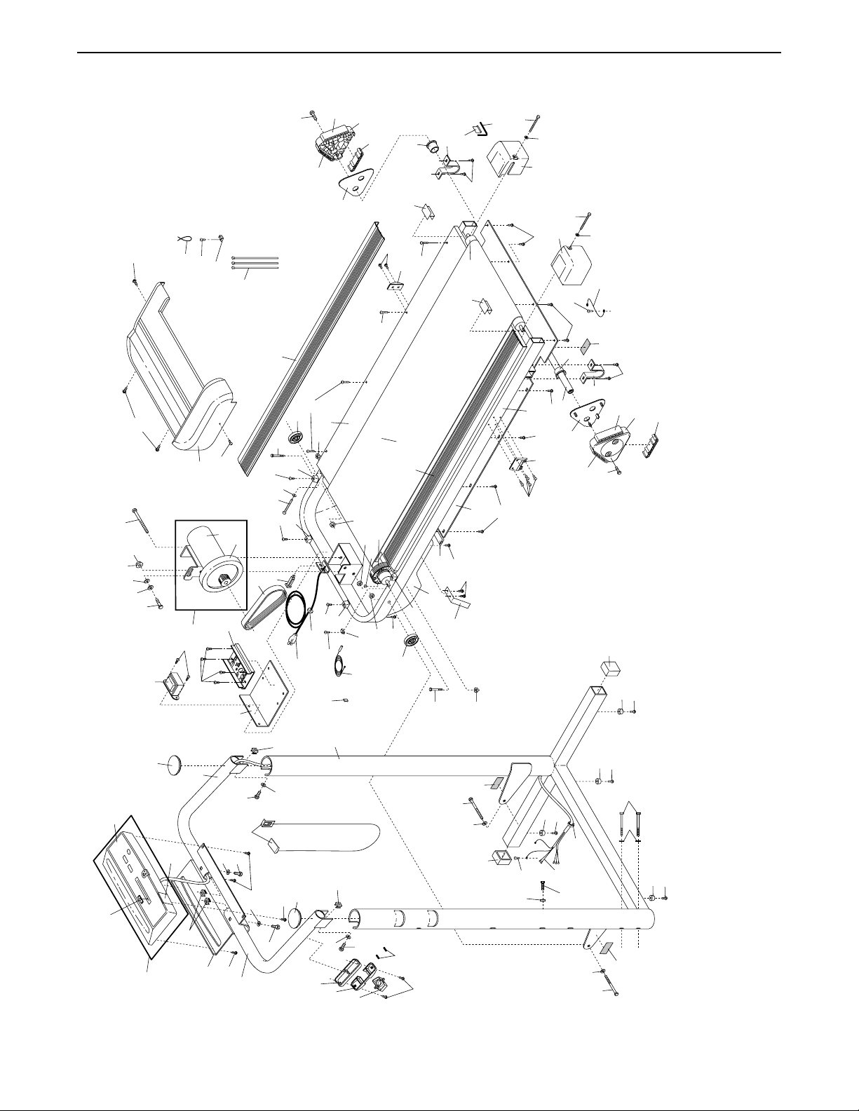
Exploded Drawing—Model No. WLTL46080 R0898E
106
107
106
61
61
85
84
83
82
63
88
89
90
91
92
101
93
43
125
61
86
78
79
67
80*
66
69
119
68
75
29
95
94
75
29
76
77
73
72
108
112
109
100
111
110
66
101
75
129
125
128
118
109
127
29
104
130
43
106
105
66
103
101
98
99
96
97
132
131
29
75
135
71
134
133
29
96
93
115
113
95
114
115
116
117
123
117
124
126
117
95
120
119
117
121
110
66
111
122
117
105
106
107
106
108
106
26
28
29
142
70
28
29
143
136
137
26
53
45
63
62
58
59
60
61
138
102
28
29
140
139
41
137
136
143
32
31
28
29
53
142
51
50
49*
65
45
63
64
52
45
56
57
57
45
53
54
56
57
55
 Loading...