

Weslo WCTL41305.0 User Manual
Model No. WCTL41305.0
www.weslo.com
Visit our website at
Serial No.
Serial Number Decal
QUESTIONS?
As a manufacturer, we are committed to providing complete
customer satisfaction. If you
have questions, or if there are
missing parts, please call:
1-888-936-4266
Mon.–Fri. 8h00 until 17h00 EST
(excluding holidays).
USER'S MANUAL
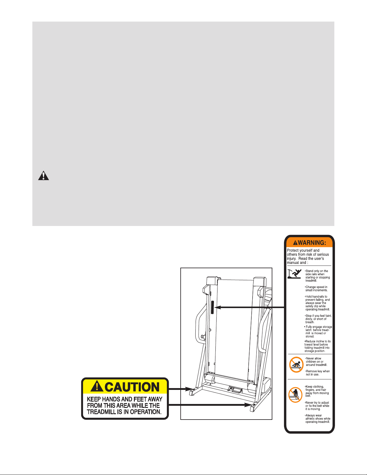
CAUTION
Read all precautions and instructions in this manual before using
this equipment. Save this manual
for future reference.

TABLE OF CONTENTS
IMPORTANT PRECAUTIONS . . . . . . . . . . . . . . . . . . . . . . . . . . . . . . . . . . . . . . . . . . . . . . . . . . . . . . . . . . . . . . . . .3
BEFORE YOU BEGIN . . . . . . . . . . . . . . . . . . . . . . . . . . . . . . . . . . . . . . . . . . . . . . . . . . . . . . . . . . . . . . . . . . . . . . .5
ASSEMBLY . . . . . . . . . . . . . . . . . . . . . . . . . . . . . . . . . . . . . . . . . . . . . . . . . . . . . . . . . . . . . . . . . . . . . . . . . . . . . . .6
OPERATION AND ADJUSTMENT . . . . . . . . . . . . . . . . . . . . . . . . . . . . . . . . . . . . . . . . . . . . . . . . . . . . . . . . . . . .10
HOW TO FOLD AND MOVE THE TREADMILL . . . . . . . . . . . . . . . . . . . . . . . . . . . . . . . . . . . . . . . . . . . . . . . . . .21
TROUBLESHOOTING . . . . . . . . . . . . . . . . . . . . . . . . . . . . . . . . . . . . . . . . . . . . . . . . . . . . . . . . . . . . . . . . . . . . . .23
CONDITIONING GUIDELINES . . . . . . . . . . . . . . . . . . . . . . . . . . . . . . . . . . . . . . . . . . . . . . . . . . . . . . . . . . . . . . .25
PART LIST . . . . . . . . . . . . . . . . . . . . . . . . . . . . . . . . . . . . . . . . . . . . . . . . . . . . . . . . . . . . . . . . . . . . . . . . . . . . . . .28
EXPLODED DRAWING . . . . . . . . . . . . . . . . . . . . . . . . . . . . . . . . . . . . . . . . . . . . . . . . . . . . . . . . . . . . . . . . . . . . .29
HOW TO ORDER REPLACEMENT PARTS . . . . . . . . . . . . . . . . . . . . . . . . . . . . . . . . . . . . . . . . . . . . . .Back Cover
LIMITED WARRANTY . . . . . . . . . . . . . . . . . . . . . . . . . . . . . . . . . . . . . . . . . . . . . . . . . . . . . . . . . . . . . . .Back Cover
WESLO is a registered trademark of ICON IP, Inc.
2

IMPORTANT PRECAUTIONS
WARNING: T
following important precautions and information before operating the treadmill.
1. It is the responsibility of the owner to ensure
hat all users of this treadmill are adequately
t
informed of all warnings and precautions.
2. Use the treadmill only as described in this
manual.
3. Place the treadmill on a level surface, with at
least 2 m (8 ft.) of clearance behind it and 0.5 m
(2 ft.) on each side. Do not place the treadmill
on any surface that blocks air openings. To
protect the floor or carpet from damage, place
a mat under the treadmill.
4. Keep the treadmill indoors, away from mois-
ture and dust. Do not put the treadmill in a
garage or covered patio, or near water.
5. Do not operate the treadmill where aerosol
products are used or oxygen is administered.
6. Keep children under the age of 12 and pets
away from the treadmill at all times.
7. The treadmill should not be used by persons
weighing more than 136 kg (300 lbs.). Never
allow more than one person on the treadmill at
a time.
o reduce the risk of burns, fire, electric shock, or injury to persons, read the
tem is damaged, the walking belt may change
peed, accelerate, or stop unexpectedly,
s
which may result in a fall and serious injury.
12. Keep the power cord and the surge suppressor away from heated surfaces.
13. Never move the walking belt while the power
is turned off. Do not operate the treadmill if
the power cord or plug is damaged, or if the
treadmill is not working properly. (See
BEFORE YOU BEGIN on page 5 if the treadmill is not working properly.)
Never start the treadmill while you are stand-
14.
ing on the walking belt. Always hold the
handrails while using the treadmill.
15. The treadmill is capable of high speeds.
Adjust the speed in small increments to avoid
sudden jumps in speed.
16. The pulse sensor is not a medical device.
Various factors, including the user's movement, may affect the accuracy of heart rate
readings. The pulse sensor is intended only
as an exercise aid in determining heart rate
trends in general.
8. Wear appropriate exercise clothes when
using the treadmill. Do not wear loose clothes
that could become caught in the treadmill.
Athletic support clothes are recommended
for both men and women.
Always wear athletic shoes. Never use the treadmill with bare
feet, wearing only stockings, or in sandals.
When connecting the power cord (see page 10),
9.
plug the power cord into a surge suppressor
(not included) and plug the surge suppressor
into a grounded circuit capable of carrying 15
or more amps. No other appliance should be on
the same circuit. Do not use an extension cord.
10. Use only a single-outlet surge suppressor that
meets all of the specifications described on
page 10.
11. Failure to use a properly functioning surge
suppressor could result in damage to the con
trol system of the treadmill. If the control sys-
17. Never leave the treadmill unattended while it
is running. Always remove the key, unplug
the power cord, and move the reset/off circuit
breaker to the off position when the treadmill
is not in use. (See the drawing on
the location of the circuit breaker.)
Do not use the hand weights at speeds faster
18.
than walking speeds. Using weights and not
holding the handrails may compromise your
ability to maintain your balance. Exercises
using weights should be attempted only by
experienced users.
19. Do not attempt to raise, lower, or move the
treadmill until it is properly assembled. (See
ASSEMBLY on page 6, and HOW TO FOLD
AND MOVE THE TREADMILL on page 21.)
You must be able to safely lift 20 kg (45 lbs.)
-
to raise, lower, or move the treadmill.
When folding or moving the treadmill, make
20.
sure that the storage latch is fully closed.
page 5 for
3
21. When using iFIT.com CDs and videos, an
lectronic “chirping” sound will alert you
e
hen the speed of the treadmill is about to
w
change. Always listen for the “chirp” and be
prepared for speed changes. In some instances, the speed may change before the
ersonal trainer describes the change.
p
22. When using iFIT.com CDs and videos, you can
manually override the speed setting at any time
by pressing the speed buttons. However, when
the next “chirp” is heard, the speed will change
to the next setting of the CD or video program.
23. Always remove iFIT.com CDs and videos from
your CD player or VCR when you are not
using them.
24. Inspect and properly tighten all parts of the
treadmill every three months.
25. Never drop or insert any object into any openng.
i
26.
DANGER: Always unplug the power
cord immediately after use, before cleaning
the treadmill, and before performing the main-
enance and adjustment procedures de-
t
scribed in this manual. Never remove the
motor hood unless instructed to do so by an
authorized service representative. Servicing
other than the procedures in this manual
should be performed by an authorized service
representative only.
27. The treadmill is intended for in-home use
only. Do not use the treadmill in any
commercial, rental, or institutional setting.
WARNING: Before beginning this or any exercise program, consult your physician. This
is especially important for persons over the age of 35 or persons with pre-existing health problems.
Read all instructions before using. ICON assumes no responsibility for personal injury or property
damage sustained by or through the use of this product.
SAVE THESE INSTRUCTIONS
The decals shown here have been placed on your treadmill. If a decal is missing,
or if it is not legible, please call the toll-free telephone number on the front cover of
this manual and order a free replacement decal. Apply the decal in the location
shown. Note: The decals are not shown at actual size.
4
BEFORE YOU BEGIN
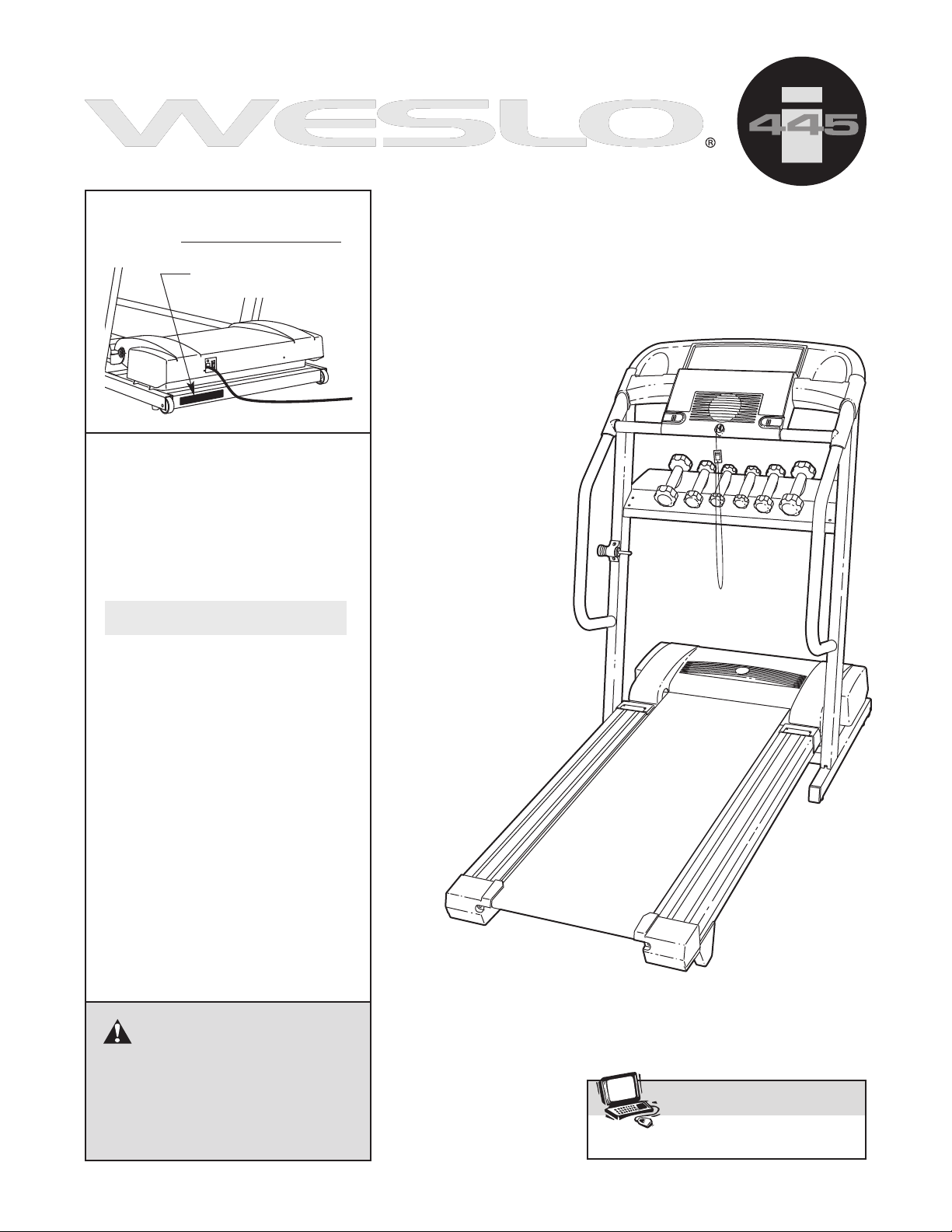
Thank you for selecting the revolutionary WESLO®445i
treadmill. The WESLO 445i treadmill combines advanced technology with innovative design to help you
et the most from your exercise program in the conve-
g
ience and privacy of your home. And when you’re not
n
exercising, the unique WESLO 445i treadmill can be
folded up, requiring less than half the floor space of
other treadmills.
For your benefit, read this manual carefully before
you use the treadmill. If you have questions after
Tray
Pulse Sensor
Handrail
reading this manual, please see the front cover of this
manual. To help us assist you, note the product model
number and serial number before calling. The model
umber of the treadmill is WCTL41305.0. The serial
n
umber can be found on a decal attached to the tread-
n
mill (see the front cover of this manual for the location).
Before reading further, please review the drawing
below and familiarize yourself with the labeled parts.
Fan
Console
Key/Clip
Walking Belt
Foot Rail
BACK
Rear Roller
Adjustment Bolts
Reset/Off
Circuit Breaker
Power Cord
Cushioned Walking Platform
RIGHT SIDE
5
ASSEMBLY
2 3/4” Bolt (47)–4
Wheel Bolt (86)–2
Star Washer (81)–4
Washer (29)–4
3/4” Screw (39)–6
1/2” Silver Screw (107)–1
Weight Rack Bolt (121)–4
Nut (122)–4
2 1/2” Bolt (56)–4
1” Tek Screw (115)–4
4” Bolt (120)–2
Assembly requires two persons. Set the treadmill in a cleared area and remove all packing materials. Do not
ispose of the packing materials until assembly is completed.Assembly requires the included allen wrench
d
and 90° screwdriver and your own Phillips screwdriver and needlenose pliers .
Note: The underside of the treadmill walking belt is coated with high-performance lubricant. During shipping, a
mall amount of lubricant may be transferred to the top of the walking belt or the shipping carton. This is a normal
s
condition and does not affect treadmill performance. If there is lubricant on top of the walking belt, simply wipe off
the lubricant with a soft cloth and a mild, non-abrasive cleaner.
For help identifying the assembly hardware, see the drawings below. Note: The assembly hardware and other
small parts are packaged in separate part bags.
1. Make sure that the power cord is not plugged in.
With the help of a second person, carefully tip the
treadmill onto its left side. Partially fold the Frame (12) so
that the treadmill will be more stable. Do not fully fold
the treadmill until it is completely assembled.
Attach the four Base Pads (97) to the bottom of the Base
(82) with four 1” Tek Screws (115) (only two Base Pads
and 1” Tek Screws are shown).
1
115
97
97
82
12
115
6
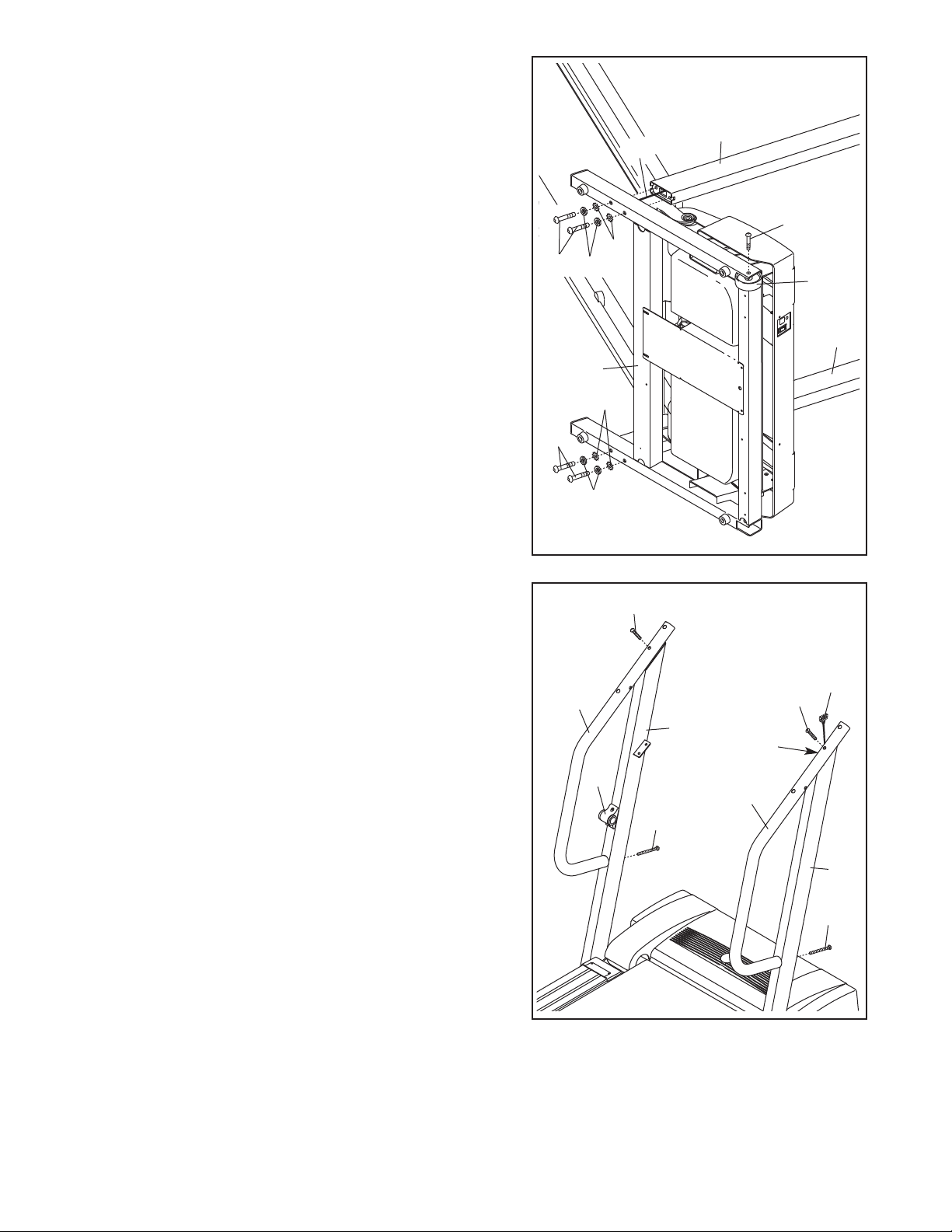
2. Identify the Right Upright (10). Note: The Left Upright (9)
has the Latch Housing (77, see step 3) attached to it.
2
Have a second person hold the Right Upright (10) near the
ase (82) as shown. Orient the Right Upright so that it is
B
angled forward (see step 3). Feed the Upright Wire
Harness (17) into the lower end of the Right Upright and
out of the upper end.
Next, hold the Right Upright (10) against the Base (82). Be
careful not to pinch the wires. Insert two 2 3/4” Bolts
(47), with two Washers (29) and two Star Washers (81),
into the Base, and
end of the Right Upright (10).
Attach a Wheel (95) to the Base (82) with a Wheel Bolt (86).
Do not overtighten the Wheel Bolt; the Wheel must be
able to turn freely.
With the help of a second person, tip the treadmill onto its
right side.
Harness (17). Have a second person hold the Left Upright
(9) near the Base (82). Orient the Left Upright so that it is
angled forward (see step 3). Attach the Left Upright and
the other Wheel (not shown) as described above. Note:
There are no wires in the Left Upright.
Be careful not to damage the Upright Wire
loosely thread the Bolts into the lower
47
47
10
17
86
81
29
95
9
82
81
29
3. With the help of a second person, set the treadmill on the
floor with the Left and Right Uprights (9, 10) vertical.
Identify the Right Handrail (93), which has a large hole in
the left side. Feed the Upright Wire Harness (17) up
through the hole in the bottom of the Right Handrail and
out of the large hole in the left side. Note: It may be helpful to use needlenose pliers to pull the Wire Harness out
of the large hole.
Set the Right Handrail (93) on the Right Upright (10).
Finger tighten a 4” Bolt (120) through the Right Upright into
the lower end of the Right Handrail. Attach the upper end
of the Right Handrail with a 2 1/2” Bolt (56).
tighten the Bolts yet.
Attach the Left Handrail (123) as described above. Note:
There is not a wire in the Left Handrail.
Do not
3
123
77
56
120
17
56
9
Large
Hole
93
10
120
7
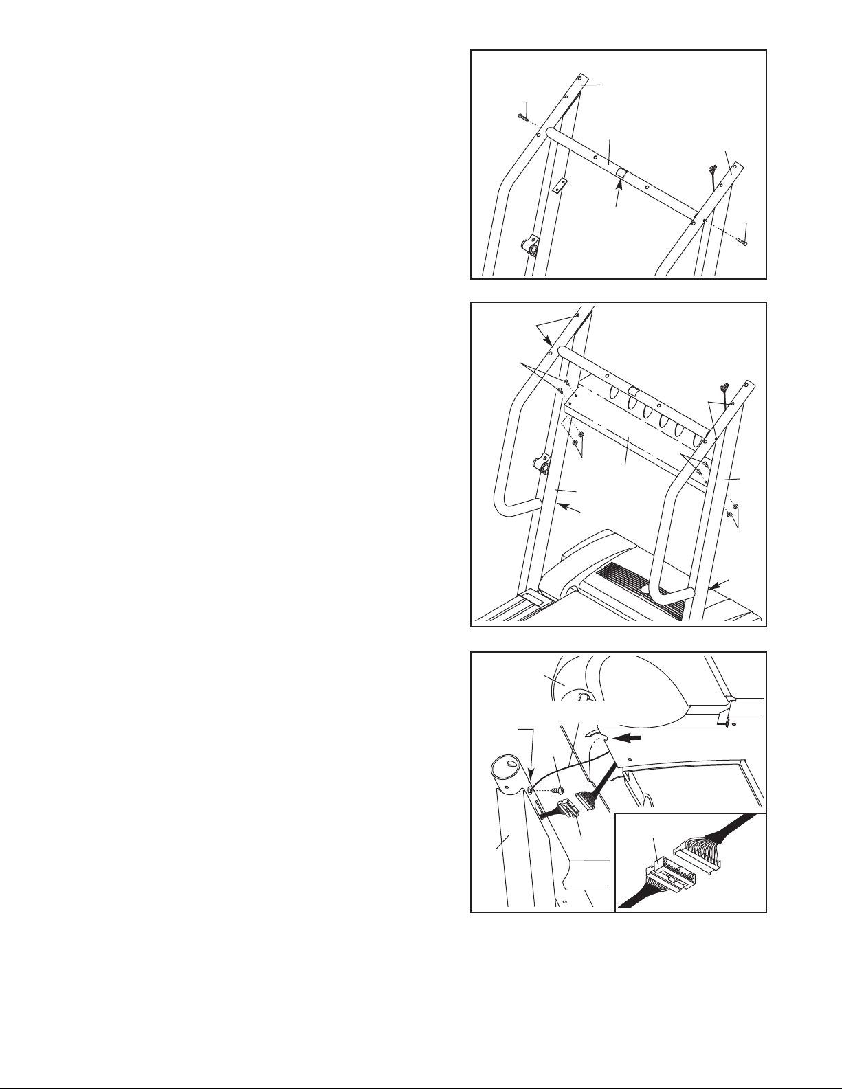
4. Hold the Console Crossbar (88) between the Handrails
(123, 93). Make sure that the square hole in the
rossbar is on top as shown. Attach the Crossbar with
C
two 2 1/2” Bolts (56).
olts yet.
B
Do not tighten the Crossbar
4
123
56
88
93
5. Attach the Weight Rack (87) to the brackets on the Left
and Right Uprights (9, 10) with four Weight Rack Bolts
(121) and four Nuts (122). Attach all of the Weight
Rack Bolts and Nuts before tightening any of them.
Firmly tighten the four 2 1/2” Bolts (56). Next, firmly
tighten the two 4” Bolts (120).
Square
Hole
5
56
121
56
121
122
87
9
120
56
10
122
120
6. Have a second person hold the Console (78) near the
Right Upright (10). Attach the ground wire from the
Console to the Right Upright with the 1/2” Silver Screw
(107). Note: There may be two small holes in the Right
Upright.
lower hole and not to the higher hole.
Connect the Upright Wire Harness (17) to the wire harness on the Console (78).
connectors properly (see the inset drawing). The
connectors should slide together easily and snap
into place. IF THE CONNECTORS ARE NOT CONNECTED PROPERLY, THE CONSOLE MAY BE DAMAGED WHEN THE POWER IS TURNED ON. Insert the
connectors into the Console.
Be sure to attach the ground wire to the
Make sure to connect the
6
Higher
Hole
10
78
Ground Wire
107
17
17
8
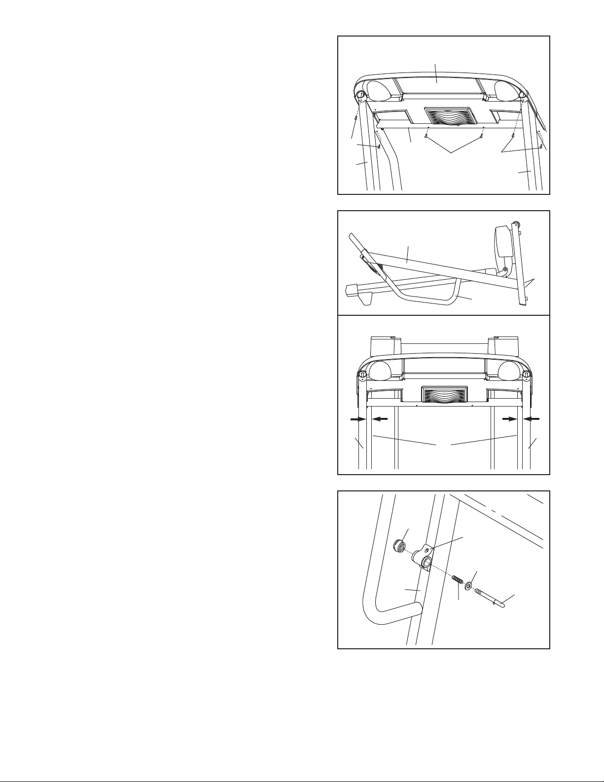
7. Set the Console (78) on the Left and Right Uprights (9,
10). Be careful not to pinch any wires. See drawing 6
n page 8. Make sure that the Upright Wire Harness (17)
o
not in the small cutout shown by the arrow.
is
Using the included 90° screwdriver and a phillips screwdriver, attach the Console (78) to the Uprights (9, 10) and
the Crossbar (88) with six 3/4” Screws (39). Start all six
Screws before tightening any of them; be careful not
to overtighten the Screws.
7
39
10
88
8
7
39
39
9
8. Lower the Uprights (9, 10) until the handrails are touching the floor.
See the lower drawing. Position the Uprights (9, 10) so
that the treadmill Frame (12) is centered between the
Uprights.
Firmly tighten the four 2 3/4” Bolts (47). Then, raise the
Uprights (9, 10) back to the vertical position.
9. Remove the knob from the pin. Make sure that the collar
and the spring are on the pin as shown. Insert the pin
into the Latch Housing (77), and tighten the knob back
onto the pin.
8
10
9
9, 10
47
Handrail
Top View
9
12
Knob
77
Collar
9
Spring
10. Make sure that all parts are properly tightened before you use the treadmill. Note: Extra hardware may
be included. Keep the included allen wrench in a secure place. The allen wrench is used to adjust the walking
belt (see page 24). To protect the floor or carpet, place a mat under the treadmill.
Pin
9

OPERATION AND ADJUSTMENT
THE PERFORMANT LUBETMWALKING BELT
Your treadmill features a walking belt coated with
PERFORMANT LUBE
MPORTANT: Never apply silicone spray or other
I
substances to the walking belt or the walking platform. Such substances will deteriorate the walking
belt and cause excessive wear.
HOW TO PLUG IN THE POWER CORD
TM
, a high-performance lubricant.
DANGER: Improper connection
of the equipment-grounding conductor can
result in an increased risk of electric shock.
Check with a qualified electrician or serviceman if you are in doubt as to whether the
product is properly grounded. Do not modify
the plug provided with the product—if it will
not fit the outlet, have a proper outlet
installed by a qualified electrician.
Your treadmill, like any other type of sophisticated
electronic equipment, can be seriously damaged by
sudden voltage changes in your home’s power.
Voltage surges, spikes, and noise interference can
result from weather conditions or from other appliances
being turned on or off. To decrease the possibility of
your treadmill being damaged, always use a surge
suppressor with your treadmill (see drawing 1 at
the right).
plug.
Plug the power cord into a surge suppressor,
and plug the surge suppressor into an appropriate
outlet that is properly installed and grounded in
accordance with all local codes and ordinances.
mportant: The treadmill is not compatible with
I
GFCI-equipped outlets.
This product is for use on a nominal 120-volt circuit,
and has a grounding plug that looks like the plug illustrated in drawing 1 below. A temporary adapter that
looks like the adapter illustrated in drawing 2 may be
used to connect the surge suppressor to a 2-pole
receptacle as shown in drawing 2 if a properly
grounded outlet is not available.
1
Grounded Outlet Box
Surge Suppressor
Grounding Pin
Grounding Pin
Grounded Outlet
2
Grounded Outlet Box
Adapter
Grounding Plug
Surge Suppressor
Use only a single-outlet surge suppressor that is
UL 1449 listed as a transient voltage surge suppressor (TVSS). The surge suppressor must have a
UL suppressed voltage rating of 400 volts or less
and a minimum surge dissipation of 450 joules.
The surge suppressor must be electrically rated
for 120 volts AC and 15 amps. There must be a
monitoring light on the surge suppressor to indicate whether it is functioning properly. Failure to
use a properly functioning surge suppressor could
result in damage to the control system of the
treadmill. If the control system is damaged, the
walking belt may change speed or stop unexpectedly, which may result in a fall and serious injury.
This product must be grounded. If it should malfunc
tion or break down, grounding provides a path of least
resistance for electric current to reduce the risk of elec
tric shock. This product is equipped with a cord having
an equipment-grounding conductor and a grounding
Lug
Metal Screw
The temporary adapter should be used only until a
properly grounded outlet (drawing 1) can be installed
by a qualified electrician.
The green-colored rigid ear, lug, or the like extending
from the adapter must be connected to a permanent
ground such as a properly grounded outlet box cover.
Whenever the adapter is used it must be held in place
-
by a metal screw.
covers are not grounded. Contact a qualified elec-
-
trician to determine if the outlet box cover is
grounded before using an adapter.
Some 2-pole receptacle outlet box
10
 Loading...