

Page 1

NSN 3920 Truck, Hand Lift, Pallet.
Manual-Hydraulic, Shipboard, HS Safety
Rating, 42-27-60XTSB
PALLET MULE
SHIPBOARD PALLET TRUCK
42-27-60XTSB
PARTS / SERVICE MANUAL
REVISED – FEBRUARY 2003
WESLEY INTERNATIONAL
3680 Chestnut Street Scottdale, GA 30079
800-241-2869 404-292-7441 404-292-8469 Fax
WWW.PALLETMULE.COM
1
Page 2

INTRODUCTION
The factory-installed oil in the Shipboard Pallet Mule is automatic transmission fluid, type dextron 2.
The hydraulic system holds approximately one pint of fluid and operates on approximately ½ pint of
fluid.
The oil level and filler plug is located on the left-hand side on the pump assembly approximately 2
inches down from the top of the pump.
To properly fill the reservoir, lower forks, remove level-filler plug, squirt fluid from squirt-type oil can
into hole until oil trickles out the bottom edge of the hole. This is the maximum amount of fluid necessary to operate properly.
The wiper seals around the top of the pump piston and lift ram are fully functional wiper rings and do
not need to be replaced unless they are damaged, as both the pump piston and lift ram can be removed
directly from and reinstalled through the wiper seals without their having to be removed.
USE OF LOCTITE WHEN NECESSARY TO INSTALL:
(A) Preparation on the B1-15.5 pump piston seal involving installation in its oversize casting bore.
1. The seal and its respective casting bore must be clean and free of debris and oil.
2. To clean: Spray the casting bore surface, and the outer perimeter of the pump seal with Locquic
Primer-Cleaner grade T, and then wipe with a clean rag.
3. Next: Spray the casting bore surface, and outer perimeter of the pump seal again with Locquic
Primer-Cleaner grade T, this time allowing to dry for approximately 5 minutes.
4. Loctite Locquic Primer-Cleaner grade T causes the Loctite retaining compound to harden faster
and insures best results. MIL Spec. 22473
(B) Application of the Loctite Retaining Compound to the B1-15.5 pump seal and its respective over-
size casting bore. MIL Spec. R46082
1. Apply a coating of retaining co mpound to the inside perimeter of the casting bore. Also apply a
coating of retaining compound to the outside perimeter seal.
2. Insert seal in casting bore: allow 1 hour for proper hardening.
3. It is of great importance that the clearances between the mating parts be completely filled in order to obtain a leak-proof seal. Make certain not to remove require material while wiping any
excess, specifically where the pump piston is involved. Loctite is a material that hardens from a
liquid state into a solid state when confined between mating parts without the presence of air.
The pump piston, lift ram and release plunger cylinders are all burnished to a #10 finish. In conjunction
with this fine finish, the Pallet Mule uses simplified packing, consisting of polyurethane O-rings and Ucups. This packing is made of the same tough, resilient material that the wheels are coated with. The
combination of polyurethane working against this fine finish means years of trouble free hydraulic operation.
2
Page 3

SAFETY AND
OPERATIONAL CONSIDERATIONS
• Read Manual before operating hand pallet jack.
• Always make sure hand pallet truck is operated by trained personnel.
• Keep hands, feet and loose clothing clear of area beneath hand pallet truck.
• Always make certain that your view is unobstructed in the direction that you are
moving.
• Do balance the load evenly on the forks.
• Do Not exceed the maximum lifting capacity as shown on the id plate.
• Do Not ride or carry personnel on hand pallet truck.
• Do Not lift loads or objects with the fork tips.
• Do Not use hand pallet truck on grades.
How to Operate
• To raise the load, pump handle until load reaches desired height
• Hold the release lever up – The truck will lower load.
• Hold brake handle up to move. Releasing brake handle will immediately apply
brakes.
Take Hand Pallet Truck out of service immediately if:
• Hydraulic pump is leaking
• Any fasteners are loose or missing
• Any part of the hand pallet truck is bent or damaged.
• Brake does not automatically hold hand pallet truck in a locked position.
3
Page 4
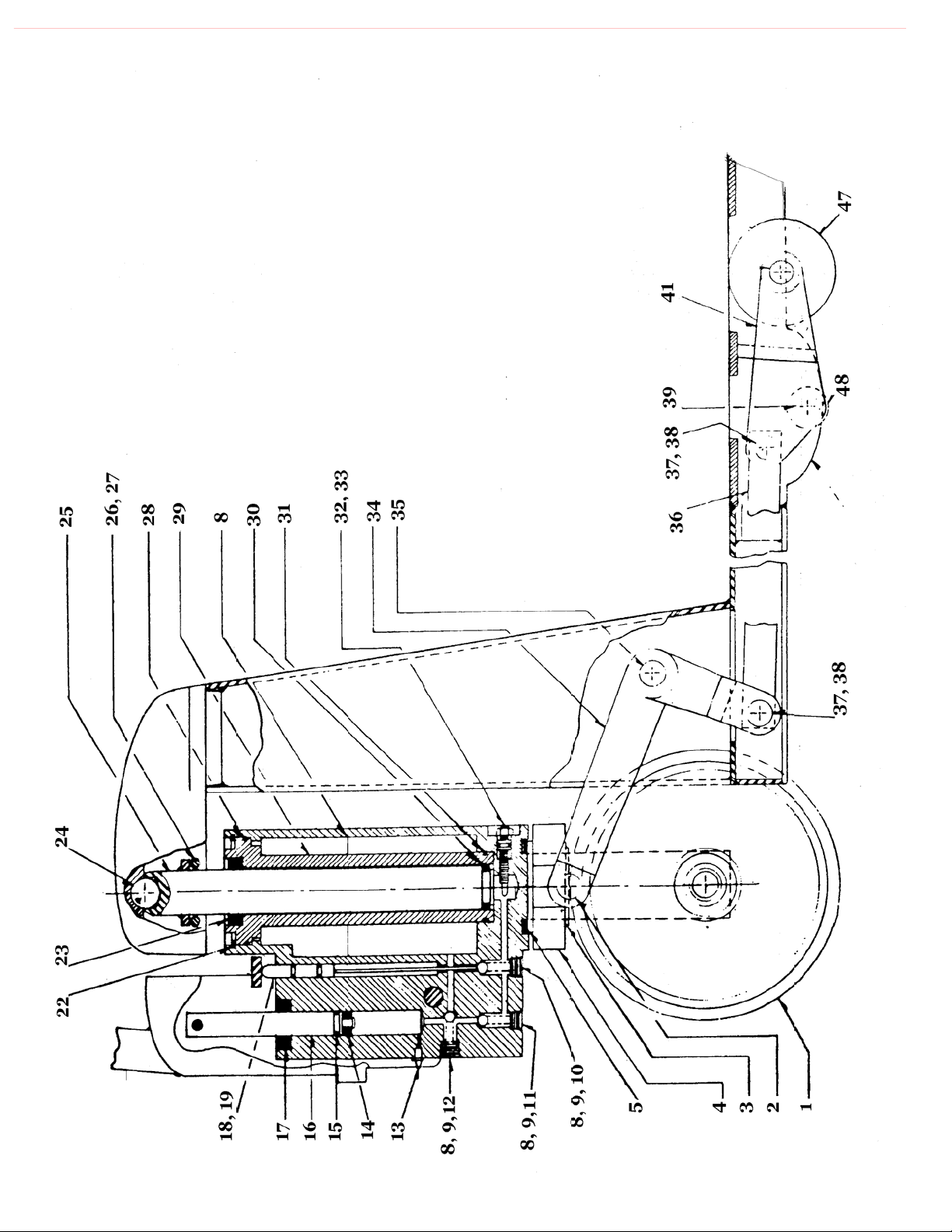
Drawing 1
(Parts List on Following Page)
SIDE VIEW
4
Page 5
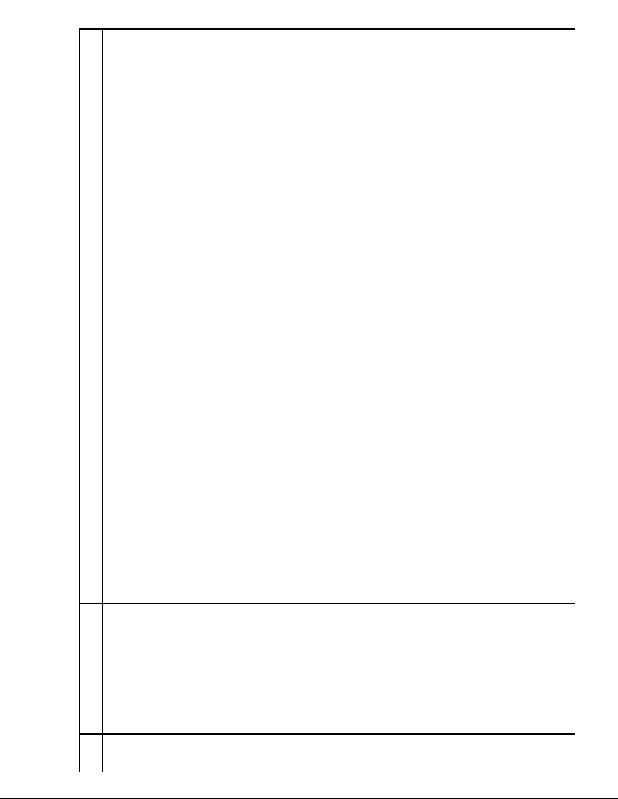
SIDE VIEW PARTS
1 DM-09 2 Steer Wheel Assembly 25 B1-26 10M SS 1 Lift Ram 10M, Stainless Steel
Item Part # Qty Description Item Part # Qty Description
3 B1-08B 1 Load Arm Snap Ring 27 B1-34B 2 Nut
2 B1-03C SS 2 Load Arm Pivot, Stainless Steel 26 B1.34 2 Stripper Bolt
5 AA-30 CR 1 Thrust Bearing 29 B1-01C 10M 1 Center Cylinder 10M
4 B1-03 Spec 1 Load Arm 28 B1-29 1 Center Cylinder O-ring, Top
9 B1-16 3 Ball 31 B1-06 1 Center Cylinder O-ring, Bottom
8 B1-20 4 Plug 30 B1-32 10M 1 Lift Ram U-cup, 10M
11 B1-33 1 High Pressure Spring 33 B1-38B 1 Restrictor O-ring
10 B1-35 1 Low Valve Ball Spring 32 B1-38 1 Restrictor
12 B1-31 1 Low Pressure Spring 34 B3-01 L7 Spec 1 Left Bell Crank
13 B1-11 1 Bleeder Valve 34 B3-01 R7 Spec 1 Right Bell Crank
15 B1-36.5 1 Air Seal 36 B6-01 Spec 2 Push Rod
14 B1-18.5 1 Pump Piston U-Cup 35 B3-02 1 Bell Crank Axle
16 B1.17.5 SS 1 Pump Piston, Stainless Steel 37 B6-02 4 Push Rod Axle
17 B1-15.5 1 Pump Piston Seal 39 B4-02 Spec 2 Load Wheel Fork Axle
19 B1-14 2 Release Plunger O-ring 42 B4-04 SS Spec 2 Load Wheel Axle, Stainless Steel
18 B1-13 SS 1 Release Plunger, Stainless Steel 41 B4-01T GF 2 Load Wheel Fork, w/ Grease Fit
23 B1-27 10M 1 Lift Ram Seal 47 A3X4POSB 4 Load Wheel
22 B1-28 1 Cylinder Snap Ring 43 B4-07 OSB 8 Load Wheel Bearing
24 B1-25 1 Load Pivot Ball 49 Roll Pin
5
Page 6
73
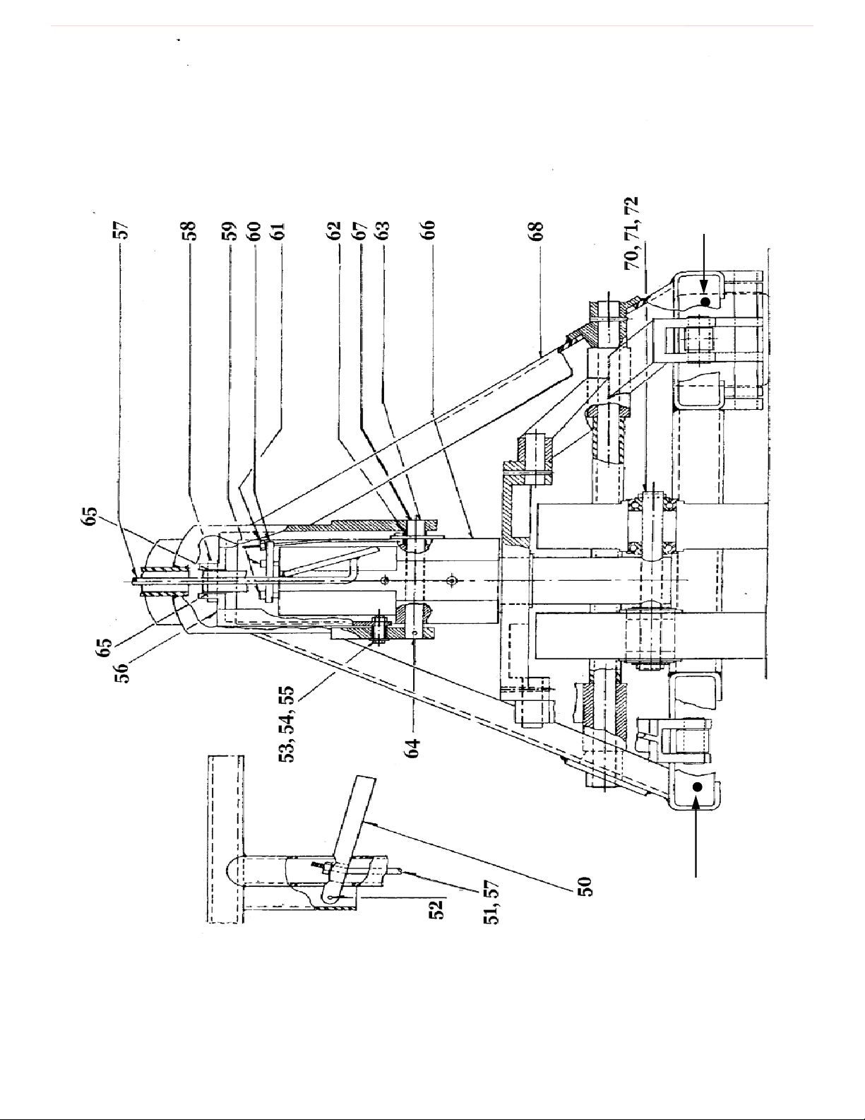
Drawing 2
(Parts List on Following Page)
Rear Pump View
73
6
Page 7
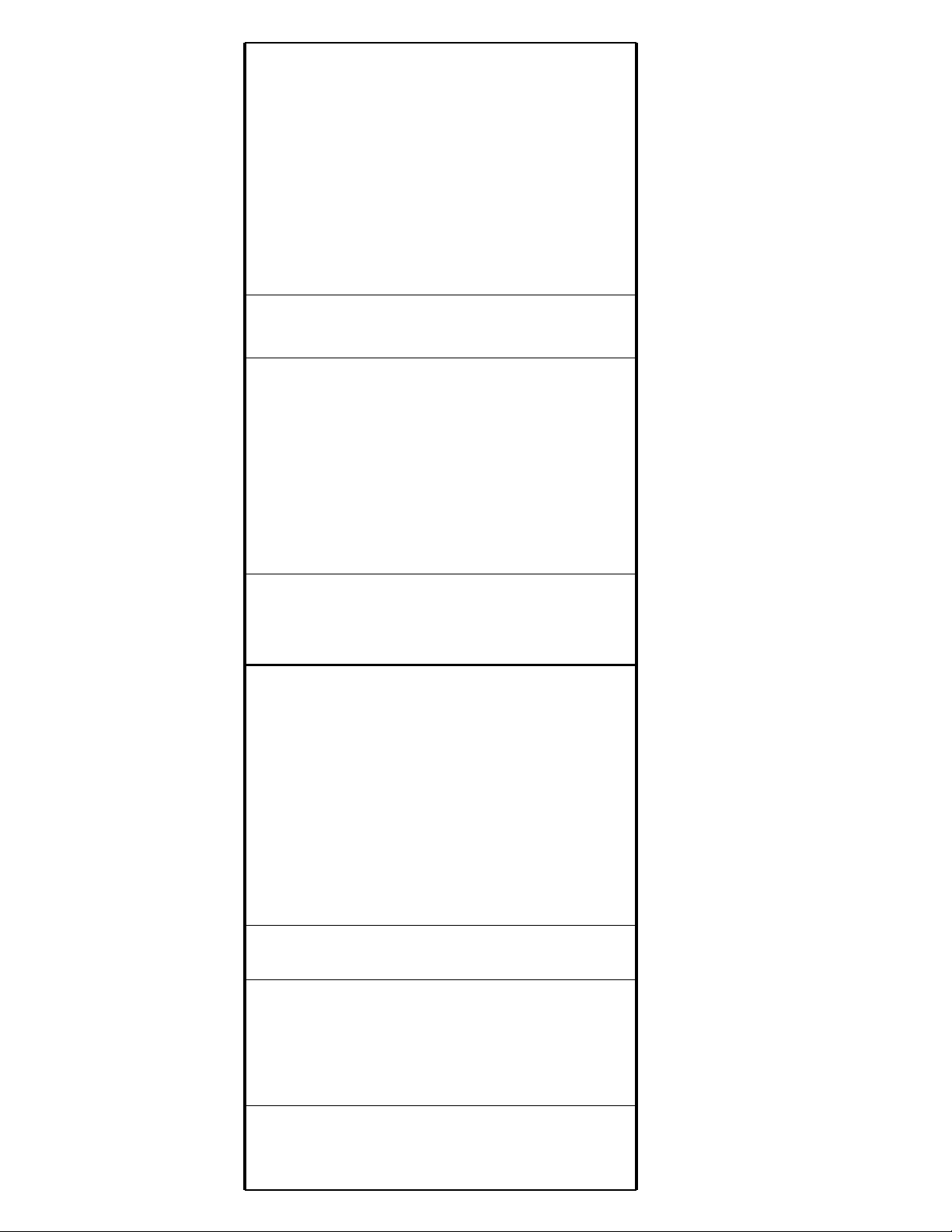
Rear Pump View Parts
Kit contains all necessary seals, wipers, o-rings, springs, and balls required to rebuild pump.
B1-10M 5/8 Hydraulic Repair Kit for Shipboard Pallet Truck (42-27-60XTSB)
Item # Part # Qty Description Item # Part # Qty Description
51 B5-B 1 Nut 63 B4-04 1 Handle Pivot
50 B5-A 1 Hand Release 62 B1-39 1 Spacer
52 B1-03B 1 Screw Post 64 B1-40R SS 1 Roll Pin, Stainless Steel
53 B1-04B 2 Cap Screw 66 B1-01 10DM 1 Hydraulic Pump Housing
55 B5-6 2 Bushing 68 B2 1 Frame
54 B1-04W SS 2 Washer, Stainless Steel 67 B4-1R SS 2 Roll Pin, Stainless Steel
57 B5-04A 1 Release Link Assembly 70 DM-20 1 Steer Wheel Axle
56 B1-04 L/R 1 Pump Link Assembly 69 B1-40CP SS 1 Cotter Pin, Stainless Steel
59 B1-42 2 Release Guide 72 B1-07 RB OSB 4 Steer Wheel Bearing
58 B1-41N 1 Lock Nut 71 B6-04 SS 2 Steer Wheel Axle Pin
61 B1-44A 1 Handle Release Adj. Nut
60 B1-43 1 Release Bar 73 DM-14 2 Static Strips
7
Page 8

SHIPBOARD PUMP
REBUILD PROCEDURE
(Requires B1-10M 5/8 Hydraulic Kit)
1. Remove B1-28 Snap Ring at top of pump cylinder
2. Fluid level under Lift Ram (B1-26 10M SS) mush have approximately 1.5 – 2” under Lift
Ram U-cup. Procedure is as follows…Place shop rag around the top of the pump to prevent
oil splatter. Firmly strike the top of the Lift Ram with a rubber mallet. The fluid back pressure will cause the B1-01 C Center Cylinder to lift out. Remove the lift ram ,part B1-26
10MSS.
3. Remove B1-04 R/L pump straps.
4. Lift out B1-17.5SS pump piston.
5. Remove both the B1-42 release guides and B1-13SS release plunger.
6. Remove the B1-20 hydraulic plugs (4 plugs), along with the B1-35, B1-33, B1-31 springs.
7. Remove B1-16 balls (3) and the B1-13 RP release plunger.
8. Keep all parts clean during the reassemble process.
9. Replace all O-rings, U-cups, Wipers, Springs, and Balls.
10. Reassemble pump in reverse order of part removal, applying one drop of non-detergent
SAE 30 oil to all o-rings, wipers and seals.
11. Fill pump in the upright position with Dextron Type 2 Automatic Transmission Fluid. Fill
to the bottom of the B1-20 filler plug, with the Lift Ram in the lowered position.
12. Open B1-11 Bleeder Valve 1/8 turn to remove air trapped under the pump piston. Close
valve when fluid runs free of air. Do not over tighten.
13. Reinstall pump and adjust B1-38 Restrictor screw to set lowering speed.
8
Page 9
9
Page 10
10
Page 11
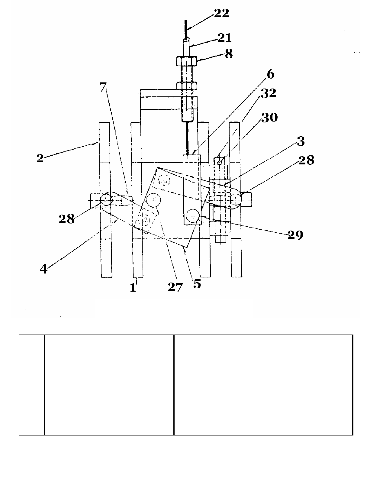
Item # Part # Qty Description Item # Part # Qty Description
1
DM-01 1 Spindle Stop 21 DM-21 1 Cable Housing
2
DM-02 2 Clapper Plate 22 DM-22 1 Cable, Stainless Steel
3
DM-03 1 Long Link 27 DM-27 1 Pivot Shoulder Screw
4
DM-04 2 Short Link 28 DM-28 2 Link Shoulder Screw
5
DM-05 1 Pivot 29 DM-29 1 Pivot Pull Shoulder
6
DM-06 2 Pivot Pull 30 DM-30 2 Roll Pin
7
DM-07 2 Heavy Duty Spring 32 DM-32 2 Clapper Plate Pin
8
DM-08 2 Clamp for Housing
Internal Brake Parts
Drawing 3
11
Page 12
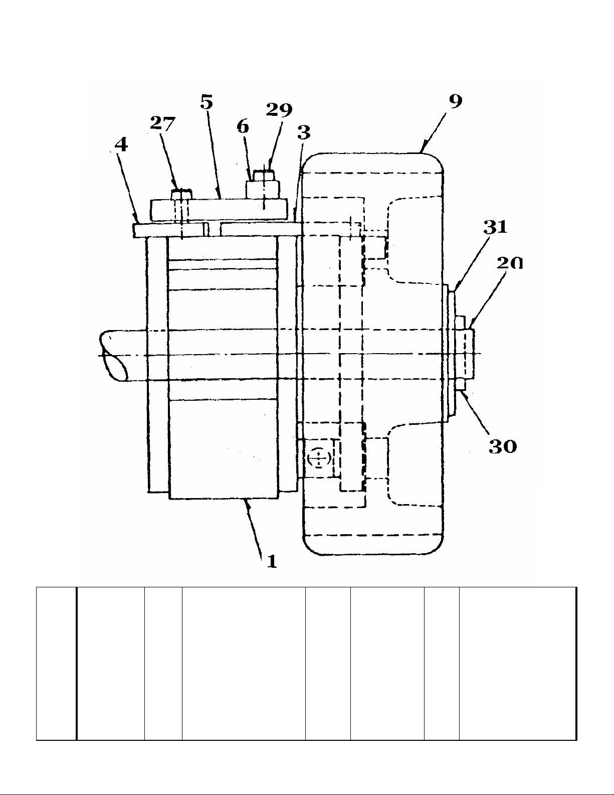
BRAKE / WHEEL PARTS
Drawing 4
Item # Part # Qty Description Item # Part # Qty Description
1
3
4
5
6
9
DM-01 1 Spindle Stop
DM-03 1 Long Link
DM-04 2 Short Link
DM-05 1 Pivot
DM-06 2 Pivot Pull
DM-09 2 Steer Wheel
20
27
29
30
31
DM-20 1 Steer Wheel Axle
DM-27 1 Pivot Shoulder Screw
DM-29 1 Pivot Pull Shoulder
DM-30 2 Roll Pin
DM-31 2 Axle Washer
12
Page 13
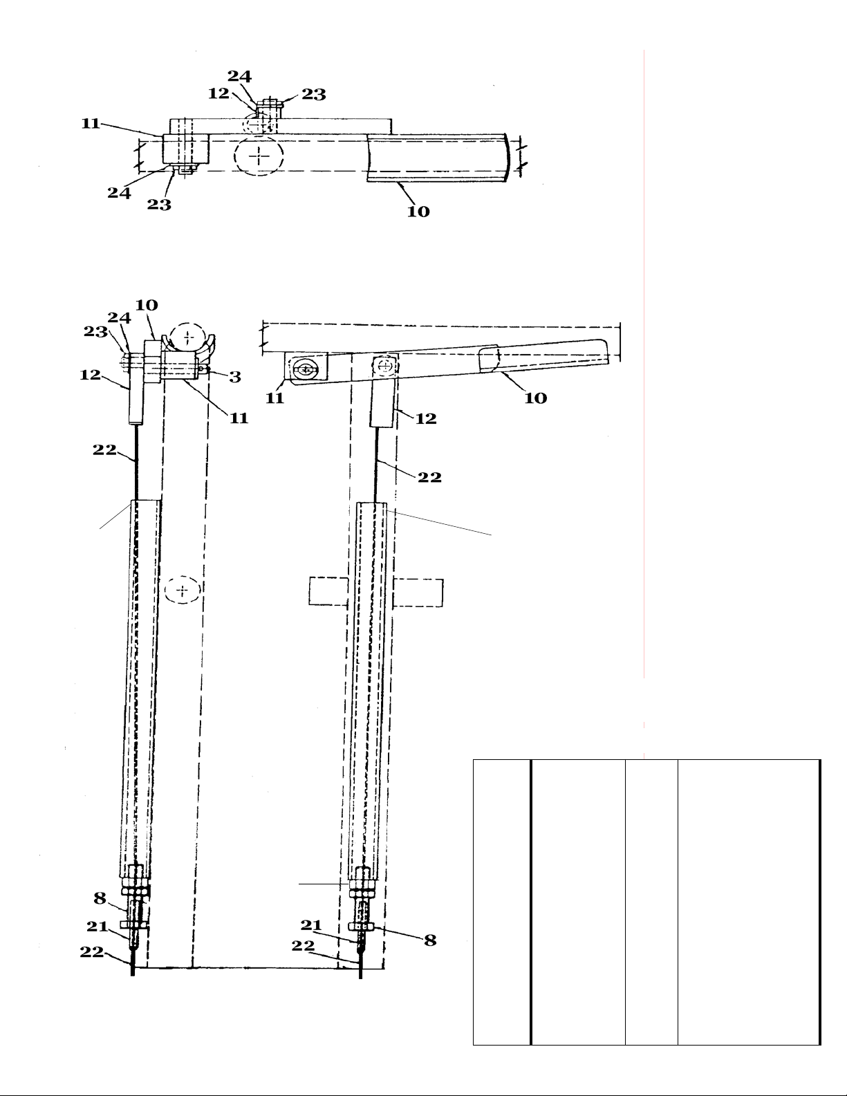
HANDLE VIEW – TOP DOWN
15 15
26
HANDLE VIEW – SIDE
Handle Parts
Drawing 5
Item # Part # Qty Description
8
10
11
12
15
21
22
23
24
26
DM-08 2 Clamp for Housing
DM-10 1 Brake Handle Assy
DM-11 1 Handle Pivot
DM-12 1 Pivot Cable Lock
DM-15 1 Cable Tube
DM-21 1 Cable Housing
DM-22 1 Cable, Stainless
DM-23 SS 4 Roll Pin, Stainless
DM-24 2 Washer
DM-26 1 Jam Nut
13
Page 14

SHIPBOARD DEADMAN BRAKE
CABLE REMOVAL AND ADJUSTMENT
1. Remove both DM-06 and DM-12 pivot pulls
2. Loosen associated set screws in the pivot pulls.
3. Remove DM-08 short and long bolts followed by the brak e cable housing and the brake ca-
ble.
4. Replace the DM-21 brake cable housing and DM-22 brake cable. Insert the DM-22 brake
cable through both the DM-08 short and long bolts. Install the DM-08 long bolt into han-
dle tube and DM-08 short bolt in the DM-01 spindle stop.
5. Replace both the DM-06 and DM-12 onto DM-22 brake cable. Insert the brake cable into
the bottom of the 3/32 hole. Tighten associated set screws.
6. To set the brake release, the DM-10 brake handle assembly Must be in Contac t with the
Steer Handle when the brake is fully disengaged.
7. If the handle is not making contact with the steer handle, proceed as follows: Turn the DM08 long & short bolts in a clockwise rotation until the DM-10 brake handle makes contact
with the steering handle.
8. If the brake is not releasing, proceed as follows: Turn DM-08 long & short bolts in counter
clockwise rotation until the brake releases with DM-10 brake handle making contact with
the steering handle.
14
Page 15

DEADMAN BRAKE ASSEMBLY &
FRAME MAINTENANCE INSTRUCTIONS
1. Inspect visually that all pins are in place.
2. Check tightness of all pivot screws (Item # 27, 28, Drawing 3)
3. Wipe down – removing excess grease and foreign materials
4. Oil any visible rust or corrosion spots.
5. One drop of moly-disulfide bearing grease on each projecting clapper plate stop pins, visible through holes in the Steer Wheel.
6. One drop of non-detergent SAE 30 oil on the top end of Item # 26 (Drawing 5) on handle.
This will migrate down into Item # 8, lubricating both Item # 21 and Item # 22.
7. One drop of non-detergent SAE 30 oil applied to the following locations:
Drawing # Item Part # Description
1 18 B1-13 SS Release Plunger, Stainless Steel
1 25 B1-26 10M SS Lift Ram 10M, Stainless Steel
1 33 B1-38B Restrictor O-ring
1 17 B1-15.5 Pump Piston Seal
1 16 B1-17.5 SS Pump Piston, Stainless Steel
5 8 DM-8 Housing Clamp, Adjustable
3 28 DM-28 Link Shoulder Screw
5 27 DM-27 Pivot Shoulder Screw
5 26 DM-26 Jam Nut
5 15 DM-15 Cable Tube, Welded to Handle
8. With pump handle turned 90 degrees, reach inside of wheels and apply oil to Clapper Plate
Pin, Item #32 (Drawing 3), one inside of each wheel.
9. Apply grease to ¼” fitting with Corrosion Control ( Mystic Mfg. P/N JT6-HI-T-P) type
grease in the following locations:
Part # Description # of Fittings
DM-09 Steer Wheel Assembly 2
B3-01 R7 Spec Right Bellcrank 2
B3-01 L7 Spec Left Bellcrank 2
B4-01T GF Load Wheel Fork, 2 3
15
Page 16

COMMON HARDWARE ITEMS
Part # Description Size Quantity
B1-03B Bolt, Socket Head 10-24 x 1 1/4 1
B1-04B Hex Bolt, Grade 5 1/4-20 x 1 1/4 2
B1-34 Bolt 3/8-16 x 4 1/4 2
B1-34B Nut, Nylon Lock 3/8-16 2
B1-40CPSS Cotter Pin, Stainless Steel 3/16 x 1 1/4 1
B1-40RSS Roll Pin, Stainless Steel 3/16 x 1 1/2 1
B1-40SS Roll Pin, Stainless Steel 3/16 x 2 10
B1-41 Shoulder Bolt 3/8-18 x 1 1/2 1
B1-41N Nut, Nylon Lock 5/16 1
B1-42 Bolt, Hex 1/4-20 x 1 1/2 2
B5-B Nut 10-24 1
B6-04SS Roll Pin, Stainless Steel 3/16 x 1 1/2 2
DM-30 Roll Pin, Stainless Steel 1/8 x 3/4 2
DM-23 Roll Pin, Stainless Steel 1/8 x 3/4 2
Suggested Spare Parts
Part # Description Quantity
A3x4 POSB Load Wheel Assembly 1
AA-30 CR Thrust Bearing 1
B1-10M 5/8 Hydraulic Repair Kit 1
B5-HRS Handle Return Spring 2
DM-02 Clapper Plate 1
DM-07 Spring for Deadman Brake 2
DM-09 Steer Wheel Assembly 1
DM-14 Static Strap Kit 2
DM-22 Brake Cable 2
DM-21 Brake Cable Housing 1
16
Page 17

Parts Index
(Order Parts from Wesley International, Cage 56250)
Part # Quantity Description Drawing #
A3X4POSB 4 Load Wheel 1
AA-30 CR 1 Thrust Bearing 1
B1-01 10DM 1 Hydraulic Pump Housing 2
B1-01C 10M 1 Center Cylinder 10M 1
B1-03B 1 Screw Post 2
B1-03 Spec 1 Load Arm 1
B1-03C SS 2 Load Arm Pivot, Stainless Steel 1
B1-04B 2 Cap Screw 2
B1-04 L/R 1 Pump Link Assembly 2
B1-04R SS 2 Roll Pin, Stainless Steel 2
B1-04W 2 Washer, Stainless Steel 2
B1-06 1 Center Cylinder O-ring, Bottom 1
B1-07RB OSB 4 Steer Wheel Bearing 2
B1-08B 1 Load Arm Snap Ring 1
B1-11 1 Bleeder Valve 1
B1-13 SS 1 Release Plunger, Stainless Steel 1
B1-14 2 Release Plunger O-ring 1
B1-15.5 1 Pump Piston Seal 1
B1-16 3 Ball 1
B1.17.5 SS 1 Pump Piston, Stainless Steel 1
B1-18.5 1 Pump Piston U-Cup 1
B1-20 4 Plug 1
B1-25 1 Load Pivot Ball 1
B1-26 10M SS 1 Lift Ram 10M, Stainless Steel 1
B1-27 10M 1 Lift Ram Seal 1
B1-28 1 Cylinder Snap Ring 1
B1-29 1 Center Cylinder O-ring, Top 1
B1-31 1 Low Pressure Spring 1
B1-32 10M 1 Lift Ram U-cup, 10M 1
B1-33 1 High Pressure Spring 1
B1-34 2 Stripper Bolt 1
B1-34B 2 Nut 1
B1-35 1 Low Valve Ball Spring 1
B1-36.5 1 Air Seal 1
B1-38 1 Restrictor 1
B1-38B 1 Restrictor O-ring 1
B1-39 1 Spacer 2
B1-40CP SS 1 Cotter Pin, Stainless Steel 2
B1-40R SS 1 Roll Pin, Stainless Steel 2
B1-41N 1 Lock Nut 2
17
Page 18

Parts Index (Continued)
Part # Quantity Description Drawing #
B1-41N 1 Lock Nut 2
B1-40SS 10 Roll Pin
B1-42 2 Release Guide 2
B1-43 1 Release Bar 2
B1-44A 1 Handle Release Adj. Nut 2
B2 1 Frame 2
B3-01 L7 Spec 1 Left Bell Crank 1
B3-01 R7 Spec 1 Right Bell Crank 1
B3-02 1 Bell Crank Axle 1
B4-01T GF 2 Load Wheel Fork, w/ Grease Fit 1
B4-02 Spec 2 Load Wheel Fork Axle 1
B4-04 XD 1 Handle Pivot 2
B4-04 SS Spec 2 Load Wheel Axle, Stainless Steel 1
B4-07 OSB 8 Load Wheel Bearing 1
B5-04A 1 Release Link Assembly 2
B5-6 2 Bushing 2
B5-A 1 Hand Release 2
B5-B 1 Nut 2
B6-01 Spec 2 Push Rod 1
B6-02 4 Push Rod Axle 1
B6-04 SS 2 Steer Wheel Axle Pin 2
DM-01 1 Spindle Stop 3, 4
DM-02 2 Clapper Plate 3
DM-03 1 Long Link 3, 4
DM-04 2 Short Link 3, 4
DM-05 1 Pivot 3, 4
DM-06 2 Pivot Pull 3, 4
DM-07 2 Heavy Duty Spring 3
DM-08 Long 2 Clamp for Housing Assembly 3, 5
DM-09 2 Steer Wheel Assembly 1,4
DM-10 1 Brake Handle Assembly 5
DM-11 1 Handle Pivot 5
DM-12 1 Pivot Cable Lock 5
DM-14 2 Static Strap (includes mounting hardware)
DM-20 1 Steer Wheel Axle 2, 4
DM-21 1 Cable Housing 3
DM-22 1 Cable, Stainless Steel 3
DM-23 SS 4 Roll Pin, Stainless 5
DM-24 2 Washer 5
DM-26 1 Jam Nut 5
DM-27 1 Pivot Shoulder Screw 3, 4
DM-28 2 Link Shoulder Screw 3
DM-29 1 Pivot Pull Shoulder 3, 4
DM-30 2 Roll Pin 3, 4
DM-31 2 Axle Washer 3, 4
DM-32 2 Clapper Plate Pin 3
1
18
 Loading...