

Page 1

Pack Mule
Power Mule
Electric Utility Vehicle Owner’s Manual
for DC-Powered Vehicles
Effective May 22, 2009
Page 2

Wesley International
3680 Chestnut Street
Scottdale, Georgia 30079
Phone (404) 292-7441 • Toll Free (800) 241-2869 • Fax (404) 292-8469
www.WesleyInternational.com
Page 3

Table of Contents
Wesley’s Service Partnership With You ................................................................................................. 4
Vehicle Inspection Checklist .................................................................................................................. 5
Safety Instructions ................................................................................................................................ 6
Operating Instructions .......................................................................................................................... 9
Maintenance ........................................................................................................................................ 12
Basic Mechanical Components ............................................................................................................. 14
Electrical Components ......................................................................................................................... 15
Transaxle Maintenance and Repair ...................................................................................................... 16
Front Wheel Steering Assembly ........................................................................................................... 22
Accelerator Linkage Assembly ............................................................................................................ 23
Troubleshooting ................................................................................................................................... 24
Warranty ............................................................................................................................................ 28
EUV Owner’s Manual 2 May 22, 2009
Page 4

Wesley’s Service Partnership With You
Introduction
Thank you for choosing a Wesley International electric utility vehicle. We are committed to delivering
excellent service before, during and after the sale. By following the operating and maintenance instructions provided in this manual, we can work together to ensure you get the best from your Pack Mule
TM
Power Mule
Record Your Product Information
Model #: Serial #:
Purchase Date:
product.
®
or
Register Your Product
PRODUCT REGISTRATION IS REQUIRED FOR WARRANTY COVERAGE. Complete and return
the enclosed warranty card immediately. See “Warranty” in this manual for coverage information.
Read This Manual
Before operating your new electric vehicle, read this manual to become familiar with the safety guidelines,
operating instructions and maintenance procedures.
If You Need Service
You will fi nd many answers to common problems in the Troubleshooting section. If do not fi nd an
answer there, we are always ready and willing to help you. Just e-mail us at [email protected] or call
800-241-2869.
Phone (404) 292-7441 • Toll Free (800) 241-2869 • Fax (404) 292-8469
Wesley International
3680 Chestnut Street
Scottdale, Georgia
www.WesleyInternational.com
EUV Owner’s Manual 2 May 22, 2009
4
Page 5
Vehicle Inspection Checklist
After Delivery
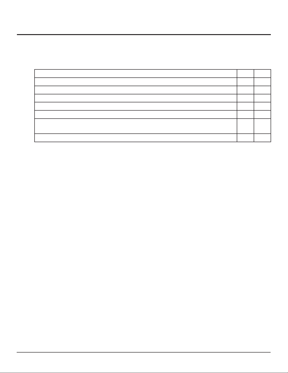
Use the following checklist to inspect your vehicle upon delivery.
Item Yes No
1. Did you receive all accessories?
2. Did you open and inspect all accessories?
3. Are any accessories damaged?
4. Are there dents or cracks on the vehicle?
5. Are the tires in good condition and properly infl ated to 60 psi?
6. If you received an optional external battery charger, is the battery charger in good
condition?
7. Are the steering controls and front steering gears operating freely and properly?
IMPORTANT: Notify the carrier immediately of any damage that occurred during shipping. Call Wesley at
800-241-2869 for all other problems or questions.
Before Operating the Vehicle
Before operating the vehicle, make sure the:
tire pressure is at least 60 psi.
•
wheel lug nuts are tight.
•
all battery connections are tight.
•
EUV Owner’s Manual 2 May 22, 2009
5
Page 6

Safety Instructions
Introduction
The responsibility for safety lies with four main groups: manufacturers, owners, operators and maintenance
personnel. As a manufacturer, our responsibility is to ensure that you are acquainted with the capabilities
of the vehicle and to recommend guidelines for safe operation based on the vehicle’s characteristics.
Training
Vehicle owners are responsible for instructing their personnel in its safe operation. Owners must explain
the vehicle’s characteristics, features and the operation of its controls. We strongly recommend that owners
fi rst become familiar with the conditions of the place where the vehicle will be operated in order to assess
their effect on safe operation. Training should occur under the conditions of the operating environment
while adhering to the safety guidelines and include:
Safety guidelines
•
Operation of the vehicle under the conditions in which it will be operated
•
Operation of all controls
•
A driving and operating test
•
Operator Qualifi cations
Operators should be selected based on their ability to safely operate the vehicle, including vision, hearing,
physical and mental capabilities. Operators must:
demonstrate a working knowledge of all controls.
•
understand all safety guidelines.
•
be able to properly drive and park the vehicle under the conditions in which the vehicle will be used.
•
know how to properly load and unload cargo and passengers.
•
recognize maintenance problems.
•
Safety Guidelines
All Pack Mule and Power Mule vehicles are designed for use on smooth surfaces in and around industrial
plants, warehouses, nurseries and greenhouses. They are not designed for use on public highways.
Driving
Follow these guidelines to safely drive the vehicle:
Read this manual before operating the vehicle.
•
Do not start the vehicle without checking the brakes fi rst.
•
Do not mount or dismount the vehicle when the key is in the ON position.
•
Do not drive the vehicle if the accelerator requires excessive pressure.
•
Do not park or operate the vehicle near fl ammable objects or in a fl ammable or hazardous
•
environment.
Use only necessary power.
•
Keep both hands on the steering wheel while operating the vehicle.
•
Accelerate and decelerate slowly.
•
EUV Owner’s Manual 2 May 22, 2009
6
Page 7

Safety Instructions (cont’d)
Safety Guidelines (continued)
Driving (continued)
Exercise extreme caution when driving in reverse.
•
Keep arms and legs within the operator’s platform while driving.
•
Do not use the vehicle to push objects.
•
Perform all recommended maintenance procedures at the specifi ed intervals.
•
Do not operate in sand, gravel or snow.
•
Do not use the accelerator to hold the vehicle at a standstill on an incline.
•
Do not allow the tires to lose contact with the ground.
•
Do not overload the vehicle above its rated load or towing capacity.
•
Make sure the area of operation is clear of trash, litter and other foreign objects.
•
Proceed around low overhangs with caution. Be sure there is enough clearance for the operator’s head
•
and the ladder and/or backrest.
Never abruptly change direction.
•
Adjust speed according to the surface conditions.
•
Always drive directly up an incline; never across.
•
Remain in the operator’s position when operating the vehicle.
•
Do not exceed the designated passenger, load or towing capacity.
•
Loading and Unloading
Follow these guidelines when loading and unloading cargo:
Turn the vehicle off while loading.
•
Do not exceed the maximum passenger or cargo load capacity.
•
Carefully and evenly position all loads.
•
Secure cargo so that nothing can easily fall off of the vehicle.
•
Be extremely careful carrying loads that extend beyond the vehicle’s deck.
•
Towing
Follow these guidelines when towing:
Turn the vehicle off when connecting to the equipment that will be towed.
•
Always use a properly installed hitch. (Optional hitches are available from Wesley International. Call
•
800-241-2869 to order.)
Do not exceed the maximum towing capacity.
•
Do not exceed 5 mph when towing.
•
EUV Owner’s Manual 2 May 22, 2009
7
Page 8

Safety Instructions (cont’d)
Fuses
Follow these instructions when servicing the electrical system:
Never install a wire instead of the proper fuse, even for a temporary fi x. It may cause extensive damage
•
and possibly a fi re.
Do not use a screwdriver or other metal object to remove fuses. Doing so may cause an electrical short
•
circuit and damage the system.
Do not modify or tamper with any part of the operating or speed control systems. All inspections and
•
adjustments must be made by a qualifi ed technician.
Wheels and Tires
When replacing tires, make sure the new wheels and tires are equivalent in diameter, rim width, off-set
and load range rating to those you are removing. An incorrect size may adversely affect the wheel and
bearing life, braking and stopping capability, handling characteristics, ground clearance and body-to-tire
clearance.
General Safety Practices
Follow these instructions each time you service the vehicle:
Completely remove and secure the deck lid before checking any portion of the drive train,
•
batteries, etc.
Chock the wheels at all times.
•
Before returning the deck lid to its normal position, make sure the battery charging plug is discon-
•
nected from the receptacle, the battery-charging wires are securely tied and all tools removed before
operating the vehicle.
EUV Owner’s Manual 2 May 22, 2009
8
Page 9
Operating Instructions
Vehicle Controls
Accelerator Pedal
Seated Vehicles: The accelerator pedal is located to the right of the brake pedal. It controls the speed of
the vehicle. It is operated with the right foot like the accelerator of an automobile.
Standing Vehicles: One pedal functions as the accelerator and the brake. The speed is proportionate to the
amount of pressure applied to the pedal. The vehicle brakes as pressure on the pedal is decreased.
Key Switch
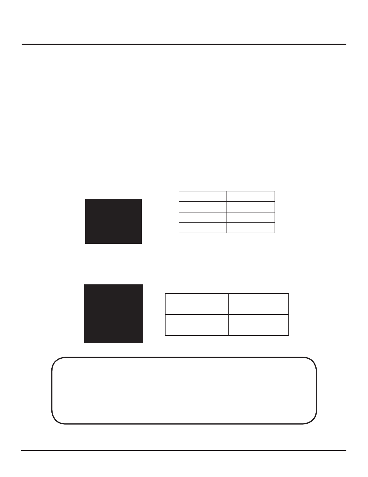
The vehicle only operates when the key is in the switch. The switch (Part # EV-E100) has three positions:
run, off and charge only.
Function Key Position
Run Right
Off Center
Charge Only Left
Directional Switch
The directional switch (Part # EV-E035) is on the instrument panel. It has three positions: forward, reverse
and neutral.
Direction Switch Position
Forward Up
Reverse Down
Park/Neutral Center
WARNING
Be sure the vehicle has completely stopped before changing directions. Rapidly changing direction
while the vehicle is moving may cause the cargo to shift and possibly injure the operator and/or others.
Damage resulting from failure to operate the vehicle according to the instructions in this manual is not
covered by the warranty.
EUV Owner’s Manual 2 May 22, 2009
9
Page 10

Operating Instructions (cont’d)
Charging
Place the vehicle in a well-ventilated area and follow these steps to charge the battery:
Remove the deck for battery ventilation.
1.
Check the battery’s water levels.
2.
Plug the charger cord into the wall receptacle and into the charger receptacle located on the rear of the
3.
vehicle.
Turn the key switch to the CHARGE position.
4.
Driving
Follow these steps to operate your Pack Mule or Power Mule vehicle:
Disconnect the battery charger.
1.
Remove the charger cord from the 120-Volt power outlet. Disconnect the charger cord from the charger
receptacle located on the rear of the vehicle. Ensure that the area is clear of all obstructions.
Turn the key switch to the ON position.
2.
Be sure that the direction switch is in the neutral position and the accelerator pedal is not depressed.
Insert the key into the ignition switch located on the instrument panel. Turn the key completely to the
right. The indicator light (BDI) located immediately above the ignition switch should come on. If not,
do not attempt to operate the vehicle.
Move the directional switch to the desired setting.
3.
The vehicle will not operate if the accelerator pedal is depressed and the directional switch is in the
middle or neutral position. (See “Key Switch” on page 8.)
NOTE: If the directional switch is left in the FORWARD or REVERSE position for 10 seconds or
more without depressing on the accelerator pedal, the delay safety feature engages, and the vehicle
will not move. The operator must turn the directional swith to the NEUTRAL position, and then back
to the desired direction to resume motion.
Press the accelerator.
4.
Depress the accelerator with your foot. The speed of the vehicle will be proportional to the amount
of pressure that is applied to the pedal. The controller regulates the speed, acting as an automatic
transmission.
Stopping.
5.
Standing Vehicles: Remove your foot from the accelerator pedal. The brake will automatically engage
upon releasing the accelerator.
Seated Vehicles: Press on the separate brake pedal.
EUV Owner’s Manual 2 May 22, 2009
10
Page 11

Operating Instructions (cont’d)
Loading
Follow these guidelines when loading:
Do not exceed the specifi ed number of passengers or load capacity for the vehicle. The maximum load
•
capacity includes the combined weight of the passengers and cargo.
Make sure the cargo is balanced and securely loaded. Do not load cargo that can easily fall off of the
•
vehicle.
Be very careful when handling cargo that is longer or wider than the vehicle.
•
Do not stack cargo so that the driver’s view is obstructed.
•
Unloading
Follow these guidelines when unloading:
•
Make sure the vehicle has come to a complete stop before passengers disembark.
•
Turn off the vehicle when unloading cargo.
•
Be careful to place cargo a safe distance away from the vehicle and out of its path.
Parking
Towing
Follow these guidelines when parking the vehicle:
Do not block fi re aisles, fi re equipment or stairways.
•
Place the directional switch in the PARK/NEUTRAL position.
•
Turn the key switch to OFF.
•
If parking on an incline, block the wheels.
•
Following these guidelines when towing:
Attach one of the optional hitches from Wesley International to the vehicle. (We offer a variety of
•
hitches. Call 800-241-2869 to order.)
Make sure the hitch is properly installed and secure.
•
Do not exceed the specifi ed towing capacity of the vehicle. The maximum capacity includes the
•
combined weight of the passengers and cargo.
Do not exceed 5 mph when towing.
•
NOTICE
Performance parameters (e.g., maximum speeds, acceleration, braking and back-up/proximity
alarm) may be adjusted on some models using a diagnostic handset. Call Wesley International at
800-241-2869 to determine if a handset is available for your vehicle and what variables may be
adjusted on your unit.
EUV Owner’s Manual 2 May 22, 2009
11
Page 12
Maintenance
Maintenance Schedule
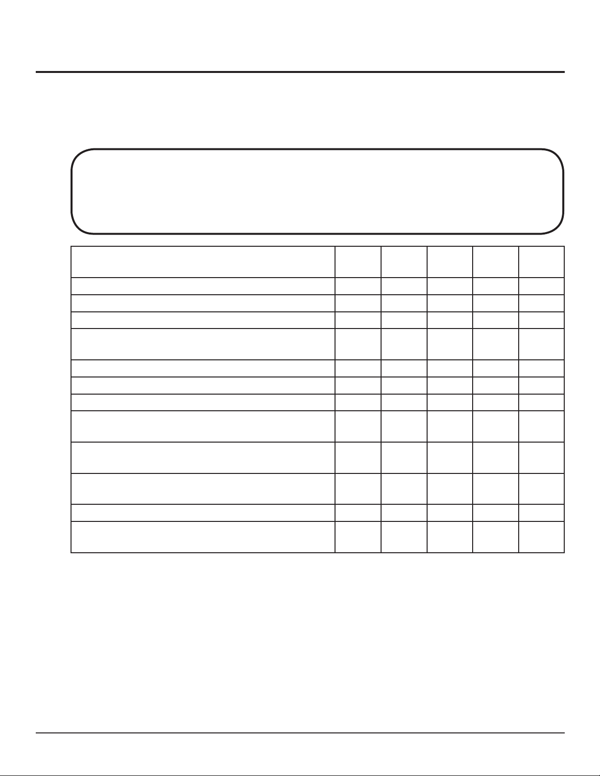
Safe, trouble-free operation of your electric utility vehicle depends on regular and proper preventive maintenance. The following chart is a guide for servicing all Pack Mule and Power Mule vehicles.
Always disconnect the battery ground cable before servicing your vehicle. Failure to do so may
result in serious injury or vehicle damage.
WARNING
Service Daily Weekly Monthly 3–6
Check all gauges. X
Check horn. X
Check BDI for battery charge. X
Plug in battery charger when the vehicle is not in
service. Leave it on charge overnight, if possible.
1
X
Check all battery cells for water levels. X
Check the pneumatic tire pressure with tires cold.
2
X
Check brake linkage. X
Check brake linings and other components for wear
and deterioration.
Oil all moving parts that do not have fi ttings with an
oilier or brush (SAE 30).
Tighten any loose battery terminals and coat terminals
with petroleum jelly.
X
X
X
Tighten nuts and bolts. X
Check the electrolyte levels of all battery cells using
a hydrometer.
3
Annually
Months
X
NOTES:
In freezing temperatures, recharge the batteries after adding distilled water to make sure the water
1.
mixes with the electrolyte properly. Otherwise, the water may freeze and damage the batteries.
The recommended tire pressure is 60 psi for all tires except the foam-fi lled and solid tires. Over or
2.
under infl ation can reduce tire life and adversely affect vehicle handling. It may also lead to sudden tire
failure, which can result in the driver losing control of the vehicle.
A hydrometer is used to determine if a battery is properly charged. It measures the specifi c gravity of
3.
the electrolyte (liquid) in the battery. The electrolyte is about 1260 in specifi c gravity when the battery
is fully charged and about 1100 in specifi c gravity when the battery is fully discharged.
EUV Owner’s Manual 2 May 22, 2009
12
Page 13
Maintenance (cont’d)
Maintenance Schedule (continued)
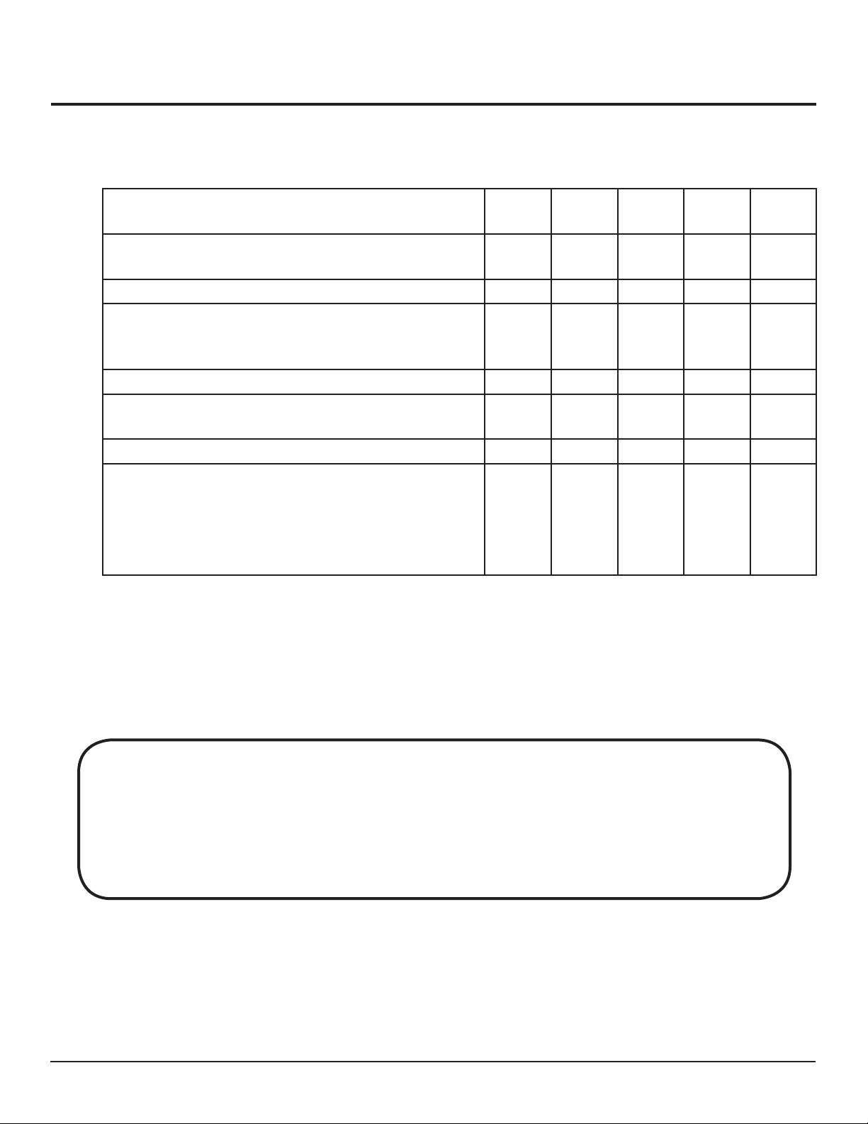
Service Daily Weekly Monthly
Grease fork pivot fi ttings and gears with automotive
grease using a grease gun.
Inspect steering operations, gear housing and linkage. X
Wash batteries with baking soda and water. (Be sure
charger is not plugged in). Dry batteries thoroughly
before returning to service.
Change oil level in transaxle. X
Clean, inspect, repack and reseal front axle and steering fork bearings.
Lubricate steering chain and sprockets. X
Check steering drive chain (link from steering wheel
to steer gear) for wear.
NOTE: This does not apply to PC 300, PC 325, and
PCT 3500 units.
3–6
Months
X
X
Annually
X
X
WARNING
Do not expose the batteries to fl ames or electrical sparks. Hydrogen gas is generated during the
battery charging operation. Hydrogen gas is explosive. Do not allow battery acid to come in contact
with skin, eyes, clothing or painted surfaces. If it gets into eyes or on skin, immediately fl ush with
water for 15 minutes and seek medical attention right away.
EUV Owner’s Manual 2 May 22, 2009
13
Page 14
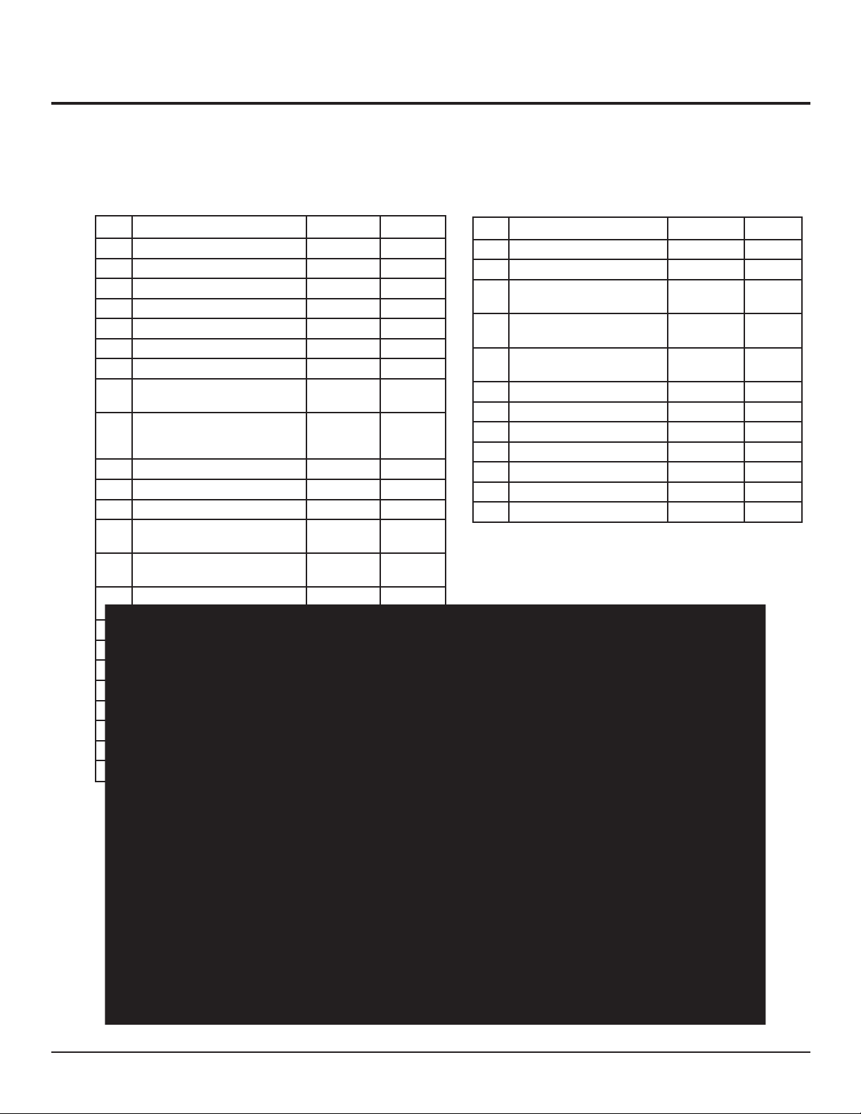
Basic Mechanical Components
The following diagram shows the basic mechanical components in all Pack Mule and Power Mule
vehicles. Although this is a drawing of the Stock Chaser SC 775, it generally applies to all vehicles.
# Description Part # Qty
3 Caution Sticker EV-A003 2
6 Transaxle 29˝ (4 lug) EV-D007 1
6 Transaxle 32˝ (4 lug) EV-D031 1
6 Transaxle 32˝ Tugger (5 lug) EV-D041 1
6 Transaxle 36˝ (4 lug) EV-D036 1
6 Transaxle 36˝ Tugger (5 lug) EV-D037 1
7 Motor, Separated Excited EV-D040 1
7 Motor, Brush Assembly
(Separated Excited Motor)
8 Battery, 6 volt, 220 amp Not for resale 4 - 24 volt
8 Battery, 6 volt, 245 amp Not for resale 4, 6, 8
8 Battery, 8 volt Not for resale 6
11 Treadle Rod EV-F022 1
15 Accelerator Pedal
(Standing Vehicles)
15 Accelerator Pedal
(Sit-down Vehicles)
16 Electronic Throttle Control
Assembly
19 Backrest Pad (Seated Vehicles) EV-F037 1
20 Drive Chain #40 EV-S001 1
21 Master Link EV-S002 1
22 Steer Rod (Stock Chaser) EV-S008 1
23 Insulator, Steering EV-S009 1
24 Lower Steering Sprocket EV-S029 1
25 Flange Bearing EV-S033 2
25A Insert Bearing EV-S011 1
EV-E193 1
6 - 36 volt
8 - 48 volt
EV-F034 1
EV-528 1
EV-E278 1
# Description Part # Qty
26 Pillow Block EV-S021 1
27 Pinion Gear EV-S022 1
28 Pneumatic Tire/Rim Assembly
(4 lug)
28 Pneumatic Tire/Rim Assembly
(5 lug)
28 Lug Nut EV-W023 4 or 5
54 Solenoid, 4 Terminal EV-E014 HD 1
66 Charger Cord EV-E026 1
68 Battery Charger, 24 volt, 25 amp EV-E028 1
68 Battery Charger, 36 volt, 25 amp EV-E075 1
68 Battery Charger, 48 volt, 25 amp EV-E099 1
70 Controller EV-E177 1
71 Steering Wheel EV-S037 1
EV-W002 4
EV-W037 4
per wheel
25A
EUV Owner’s Manual 2 May 22, 2009
14
Page 15

Electrical Components
The following table lists all of the parts in the electrical system.
Part Part Number QTY
Motor EV-D040 1
Resilient Bumper (Inside Motor Spine) EV-D030 1
Key Switch, 3-Position EV-E100 1
Horn (24, 36 and 48 volt vehicles) EV-E130 1
Battery Discharge Indicator (24 and 36 volt vehicles) EV-E093 1
Battery Discharge Indicator (48 volt vehicles) EV-E126 1
Solenoid, 4-Terminal (24, 36 and 48 volt vehicles) EV-E014 HD 1
10 Amp Fuse EV-E015 1
Fuse Holder EV-E016 1
Charger Receptacle EV-E027 1
Charger Cord EV-E026 1
Battery Charger, 24 volt EV-E028 1
Battery Charger, 36 volt EV-E075 1
Battery Charger, 48 volt EV-E099 1
DC Motor Controller, 350 amp EV-E177 1
External Resistor for Controller EV-E125 1
Electronic Throttle Control - Stand-up Units (24, 36 and 48 volt
vehicles)
Electronic Throttle Control - Seated Units (24, 36 and 48 volt
vehicles)
Direction Switch - Toggle
(all models except PC 300, PC 325, PCT 3500)
Direction Switch - Rocker (for PC 300, PC 325, PCT 3500) EV-E156 1
Horn Button (all models except PC 300, PC 325, PCT 3500) EV-E041 1
Horn Button - Foot Operated (for PC 300, PC 325, PCT 3500) EV-E120 1
Key Replacement (set of 2) EV-E160 1
Seat Safety Switch - Seated Unites EV-E127 1
Brake Light Switch EV-E119 1
EV-E278 1
EV-E528 1
EV-E035 1
EUV Owner’s Manual 2 May 22, 2009
15
Page 16

Transaxle Maintenance and Repair
Introduction
Important considerations in assembling and disassembling the transaxle for the Pack Mules and Power
Mules include cleanliness, replacement of bearings and seals, careful removal of snap rings, and the application of adequate torque on bolts, bearings and screws. For these procedures, the proper tools are required.
Some of the service operations require special tools, e.g., oil seal, bearing and slide hammer pullers.
Wesley International recommends that original Wesley service parts be used if parts need to be replaced.
Call 800-241-2869 to order replacement parts.
All maintenance personnel should be aware that the
transaxle is a precision assembly, and as such, repair
and replacement of parts must be done with great care
in a clean environment. The following are general
recommendations that relate to working on the transaxle:
Handle all gears with extreme care.
•
Degrease the transaxle assembly before disassembling.
•
Clean parts in a small wash tank prior to assembly.
•
Replace bearings, seals, and O-rings if removed, regardless of hours of use.
•
Replace nuts used on the ring gear and brake installation during service regardless of the hours
•
of use.
Remove bearings and seals with special pullers.
•
When removing the cover plate, position the transaxle over a drain pan.
•
Bearing caps are marked for identifi cation. Letter or numbers are stamped in horizontal or vertical
•
positions. During reassembly, use caution to not damage sealing surfaces such as the housing sealing
surfaces. Snap rings must be removed or installed with care to prevent damage to bearings, seals and
bearing boxes.
Use soft, clean, lintless towels to dry components after cleaning.
•
Do not air dry bearings with compressed air.
•
Apply anti-seize compound to the axle shaft spline to prevent wear and corrosion.
•
Use SAE 90 wt. (ISO 220) gear oil. (The vehicle uses 12 oz. of oil when empty.)
•
Safety glasses should be worn at all times
when assembling and disassembling the
transaxle.
WARNING
EUV Owner’s Manual 2 May 22, 2009
16
Page 17

Transaxle Maintenance and Repair (cont’d)
Torque Information
Apply the following torque to the components listed below:
Differential Bearing Caps ..................................................................................................... 35–45 Ft. Lbs.
Ring Gear Bolts ..................................................................................................................... 35–45 Ft. Lbs.
Cover Plate Screws ................................................................................................................ 18–25 Ft. Lbs.
Brake Hardware .................................................................................................................... 23–35 Ft. Lbs.
Spindle Nut ............................................................................... 65–75 Ft. Lbs. (Then tighten to next slot.)
EUV Owner’s Manual 2 May 22, 2009
17
Page 18
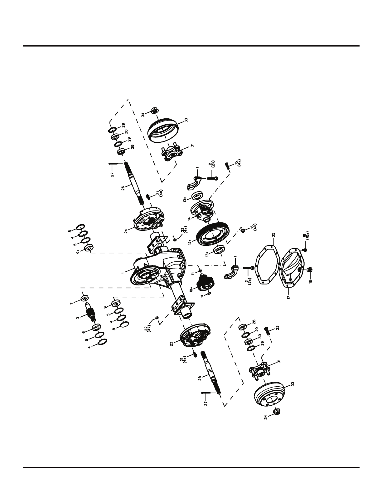
Transaxle Maintenance and Repair (cont’d)
Pack Mule Transaxle Assembly
EUV Owner’s Manual 2 May 22, 2009
18
Page 19

Transaxle Maintenance and Repair (cont’d)
Pack Mule Transaxle Parts List
# Part Part Number QTY
3 Gear, Input See Kit 1
4 Ring, Retaining EV-T016 3
5 O-Ring EV-T014 3
6 Bearing, Ball EV-T015 1
7 Bearing, Ball EV-T013 1
8 Plug, End Cap EV-T017 2
9 Bearing, Ball EV-T011 2
10 Gear, Intermediate Assembly See Kit 1
11 O-Ring EV-T010 2
12 Gear, Final Drive See Kit
13 Bearing, Ball EV-T008 2
15 Screw, Cap EV-T006 4
16 Nut, Lock EV-T007 4
17 Plate, Cover EV-T018 1
18 Plug, Fill EV-T020 1
19 Screw, Cover Plate EV-T021 10
23 Brake Assembly, Left Hand Shoe Type EV-T054 1
23 Brake Assembly, Left Hand Shoe Type (Stock Chaser) EV-T054-S 1
24 Brake Assembly, Right Hand Shoe Type EV-T055 1
24 Brake Assembly, Right Hand Shoe Type (Stock Chaser) EV-T055-S 1
25 Shaft, Axle 29˝ Left Hand (15 1/4˝ length) EV-T023-29 1
25 Shaft, Axle 32˝ Left Hand (18 1/8˝ length) EV-T023-32 1
25 Shaft, Axle 36˝ Left Hand (23 1/4˝ length) EV-T023-36 1
26 Shaft, Axle Right Hand EV-T025 1
28 Seal, Oil EV-T030 2
29 Ring, Retaining EV-T029 4
30 Bearing, Ball EV-T028 2
31, 32, 33 Hub and Drum – 4-lug assembly with studs EV-T058 2
34 Nut, Flange Hex EV-T064 2
Kit Kit, Gear Set (Includes #3, #10, #12) EV-T065 1
EUV Owner’s Manual 2 May 22, 2009
19
Page 20
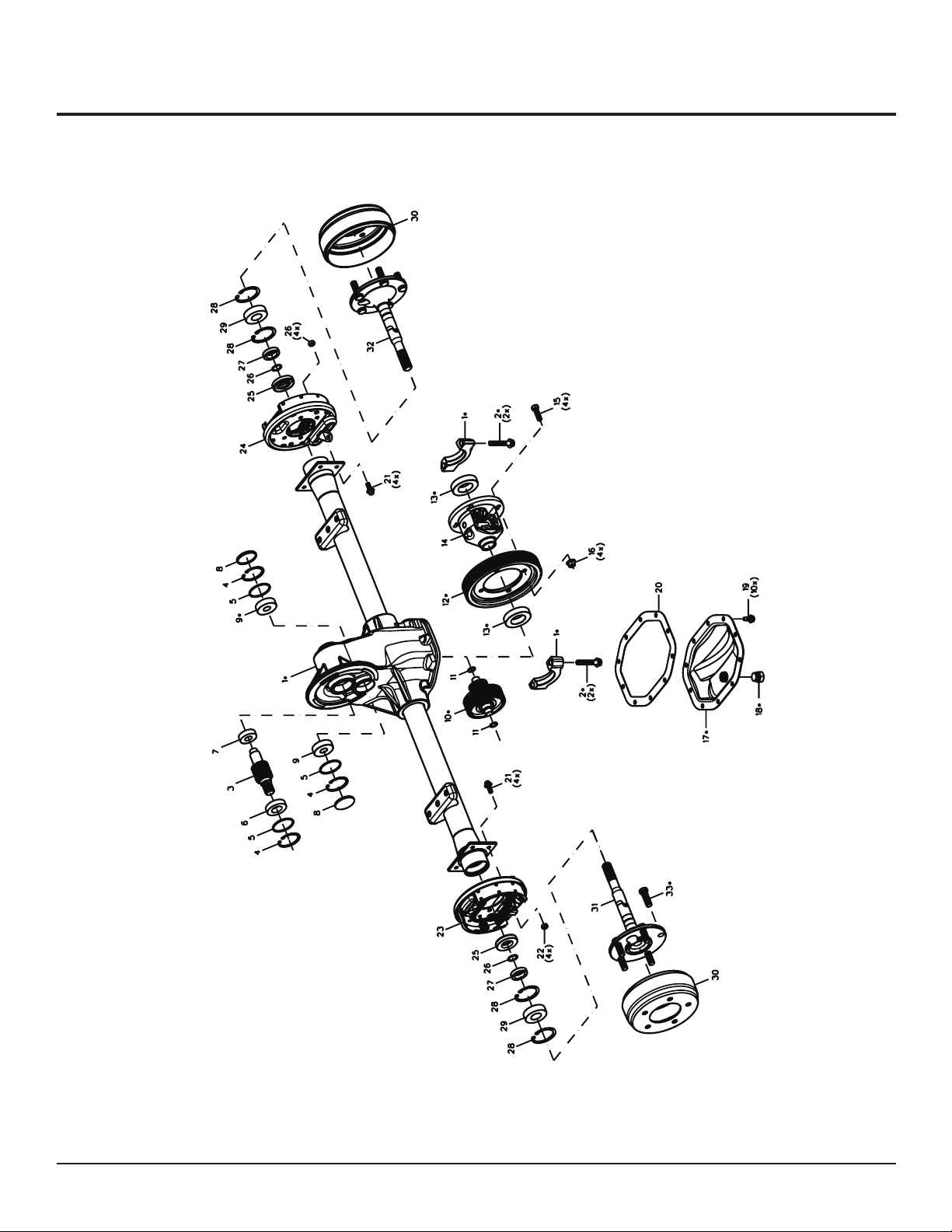
Transaxle Maintenance and Repair (cont’d)
Power Mule Tugger Transaxle Assembly
EUV Owner’s Manual 2 May 22, 2009
20
Page 21

Transaxle Maintenance and Repair (cont’d)
Power Mule Tugger Transaxle Parts List
# Part Part Number QTY
3 Gear, Input See Kit 1
4 Retaining, Ring EV-T016 3
5 O-Ring EV-T014 3
6 Bearing, Ball EV-T015 1
7 Bearing, Ball EV-T013 1
8 Plug, End Cap EV-T017 2
9 Bearing, Ball EV-T011 2
10 Gear, Intermediate Assembly See Kit 1
11 O-Ring EV-T010 2
12 Gear, Final Drive See Kit 1
13 Bearing, Ball EV-T008 2
15 Screw, Cap EV-T006 4
16 Nut, Lock EV-T007 4
17 Plate, Cover EV-T018 1
18 Plug, Fill EV-T020 1
19 Screw, Cover Plate EV-T021 10
23 Brake Assembly, Left Hand Shoe Type EV-T054 1
23 Brake Assembly, Left Hand Shoe Type (Stock Chaser) EV-T054-S 1
24 Brake Assembly, Right Hand Shoe Type EV-T055 1
24 Brake Assembly, Right Hand Shoe Type (Stock Chaser) EV-T055-S 1
25 Seal, Oil EV-T076 2
26 Ring, Retaining EV-T077 2
27 Ring, Retaining, Wheel Bearing EV-T078 2
28 Ring, Retaining EV-T079 4
29 Bearing, Ball EV-T080 2
30 Drum, Brake (5 lug) EV-T075 2
31 Shaft, Left Hand Axle 32˝ EV-T081-32 1
31 Shaft, Left Hand Axle 36˝ EV-T081-36 1
32 Shaft, Right Hand Axle EV-T082 1
Kit Kit, Gear Set (Input, Intermediate Assembly, Final Drive) EV-T083 1
37 Drum Assembly (5 lug) EV-T075 1
EUV Owner’s Manual 2 May 22, 2009
21
Page 22
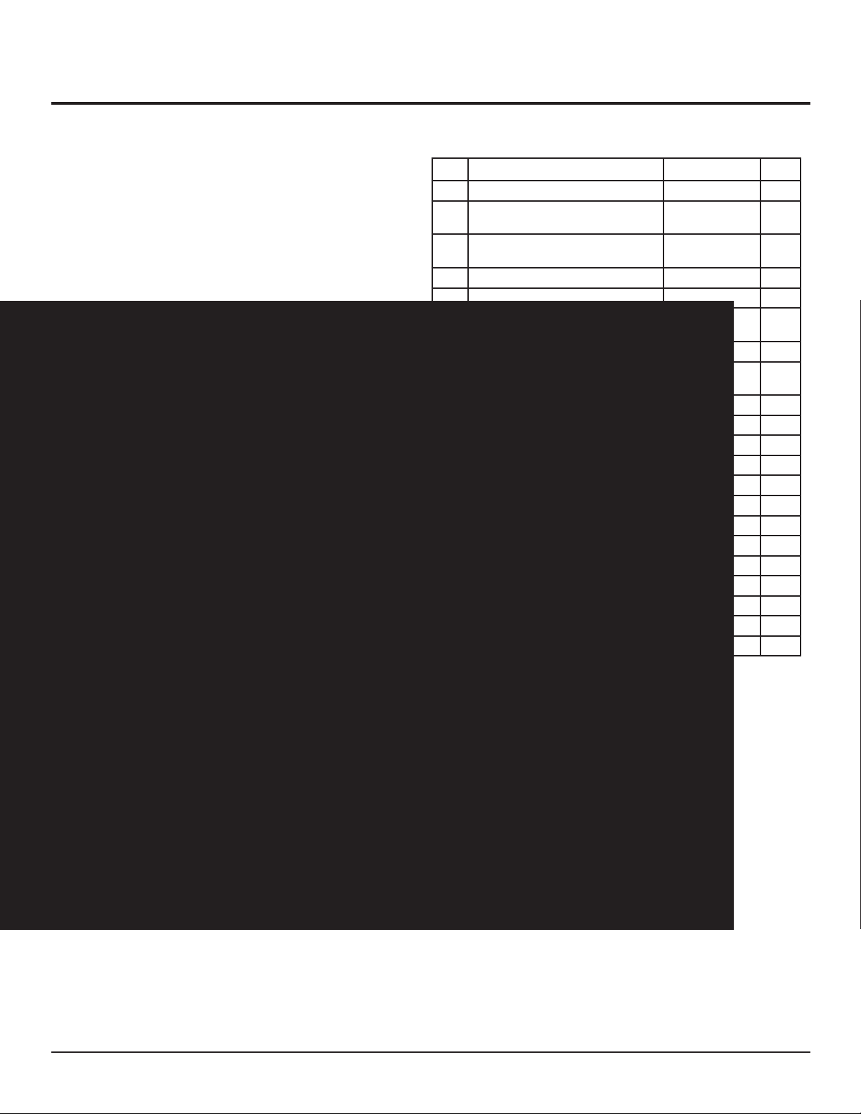
Front Wheel Steering Assembly
Front Wheel Assembly
# Description Part # Qty
1 Dual Fork Assembly EV-W016 1
1 Dual Fork Assembly, for PC series units
(Not Shown)
1 Dual Fork Assembly, for PMT series
units (Not Shown)
2 Dual Front Wheel Axle, 1˝ X 18˝ EV-W017 1
3 Sleeve EV-W007 2
3 Sleeve, for PMT series/Wide Tire units
(Not Shown)
4 Spacer EV-W014 2
4 Spacer, for PMT series/Wide Tire units
(Not Shown)
5 1˝ Flat Washer EV-W027 6
6 1˝ Lock Washer EV-W026 2
7 1˝ Slotted Hex Nut EV-W006 4
8 Hub with 4 Studs EV-W001 2
8 Hub with 5 Studs EV-W034 2
9 Race, Bearing EV-W010 6
10 Tapered Roller Bearing EV-W009 6
11 Bushing, 1˝ X 1.25˝ X 0.625˝ EV-W011 1
12 Bushing, 1˝ X 1.25˝ X 0.5˝ EV-W011-S 1
13 Seal, Oil EV-W008 6
14 1˝ Thin Slotted Hex Nut EV-W013 1
15 Pin, Cotter 3/16˝ – 1 1/4˝ EV-W025 1
16 Lug Nuts EV-W023 4 or 5
EV-W016-PC 1
EV-W016-PMT 1
EV-W007L 2
EV-W011 2
EUV Owner’s Manual 2 May 22, 2009
22
Page 23
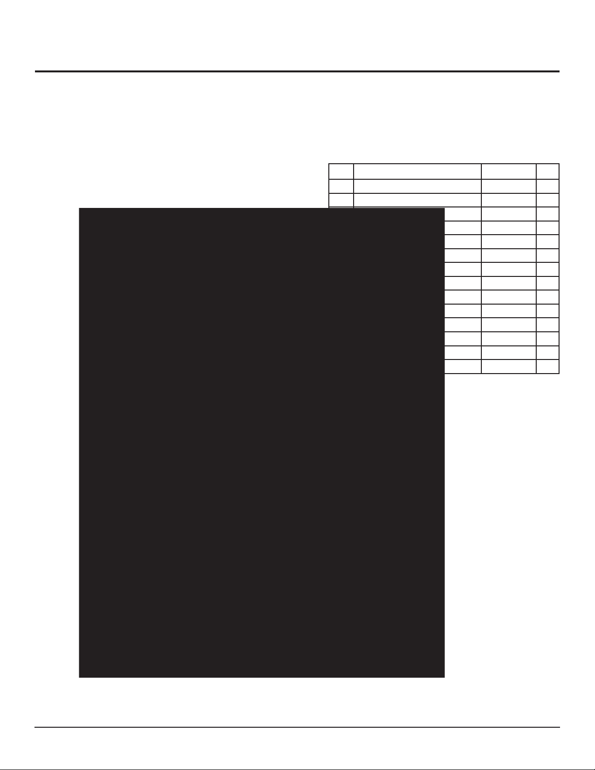
Accelerator Linkage Assembly
Accelerator Linkage (Standing Vehicles Only)
# Description Part # Qty
150 ETC Throttle Assembly EV-E278 1
151 Chain EV-F216 1
152 Clevis Pin, 5/16˝ EV-D004 1
153 Cotter Pin, 1/8˝ EV-D016 1
157 Yoke End, 5/16˝ - 24 EV-D015 1
158 Spring EV-D006 3
159 Yoke End, 1/2˝ Right Hand Tread EV-D001 2
160 Brake Rod, 1/2˝ EV-D005 2
161 Yoke End, 1/2˝ Left Hand Tread EV-D003 2
162 Clevis Pin, 1/2˝ – 1 1/2˝ EV-D010 4
163 Lockwasher, 1/2˝ EV-D011 2
164 Cotter Pin EV-D012 4
165 Hex Nut, 1/2˝ - 20 EV-D017 2
166 Flat Washer, 1/2˝ EV-D018 4
EUV Owner’s Manual 2 May 22, 2009
23
Page 24

Troubleshooting
Introduction
Be sure to follow all safety precautions when checking or repairing any part of the vehicle. Electrical
adjustments control system adjustments should only be made by qualifi ed personnel due to the use of
special equipment and instruments. If you have questions about the sensitivity or diffi culty of an adjustment, call Wesley International at 800-241-2869.
Troubleshooting Tips
Problem Possible Causes What to Do
Vehicle does not run
Motor Send the motor to an authorized motor
service center or replace the motor.
Small 10 amp fuse blown Trace the wires from the fuse and check
for a short (any bare wire that touches
the chassis or common ground wire).
Faulty control circuit:
Solenoid
•
Battery
•
Key Switch
•
Fuse
•
Faulty batteries Check electrolyte levels with a hydrom-
Malfunction of motor controller Check controller faults.
Replace the faulty component.
Check all connections to ensure that all
are clean and tight.
eter, and replace batteries if necessary.
Consult the manufacturer and replace if
necessary.
Motor runs in the
wrong direction
Vehicle loses speed
Reversed toggle switch wires Check the forward and reverse toggle
switch for proper connections.
Malfunction of solid state DC motor
controller or accelerator
EUV Owner’s Manual 2 May 22, 2009
24
Consult the manufacturer and replace if
necessary.
Page 25

Troubleshooting (cont’d)
Troubleshooting Tips (continued)
Problem Possible Causes What to Do
Rough or insuffi cient
braking
Battery charger does
not operate
Batteries do not fully
recharge
Worn brake shoes Replace and adjust brake shoes.
Blown fuse or tripped circuit breaker Inspect the circuit and replace the fuse
or reset the circuit breaker.
Faulty connections Check all battery and charger
connections.
Batteries fully charged Unplug the battery charger.
Battery charger failure Replace the battery charger.
Battery fl uid level low Check water level of batteries and fi ll
with distilled water. (DO NOT OVER
FILL.)
Batteries worn out After allowing enough time for the
batteries to recharge, check specifi c
gravity with a hydrometer.
Replace batteries, if necessary.
EUV Owner’s Manual 2 May 22, 2009
25
Page 26
Troubleshooting (cont’d)
Diagnosing Faults
The controller includes a number of features designed to help the user track down operational, wiring, or
internal controller faults. The diagnostic LED mounted next to the calibrator connectors on the front of the
controller serves as a simple diagnostic tool. Use the table below to identify faults. Faults are cleared by
re-initiating the start sequence.
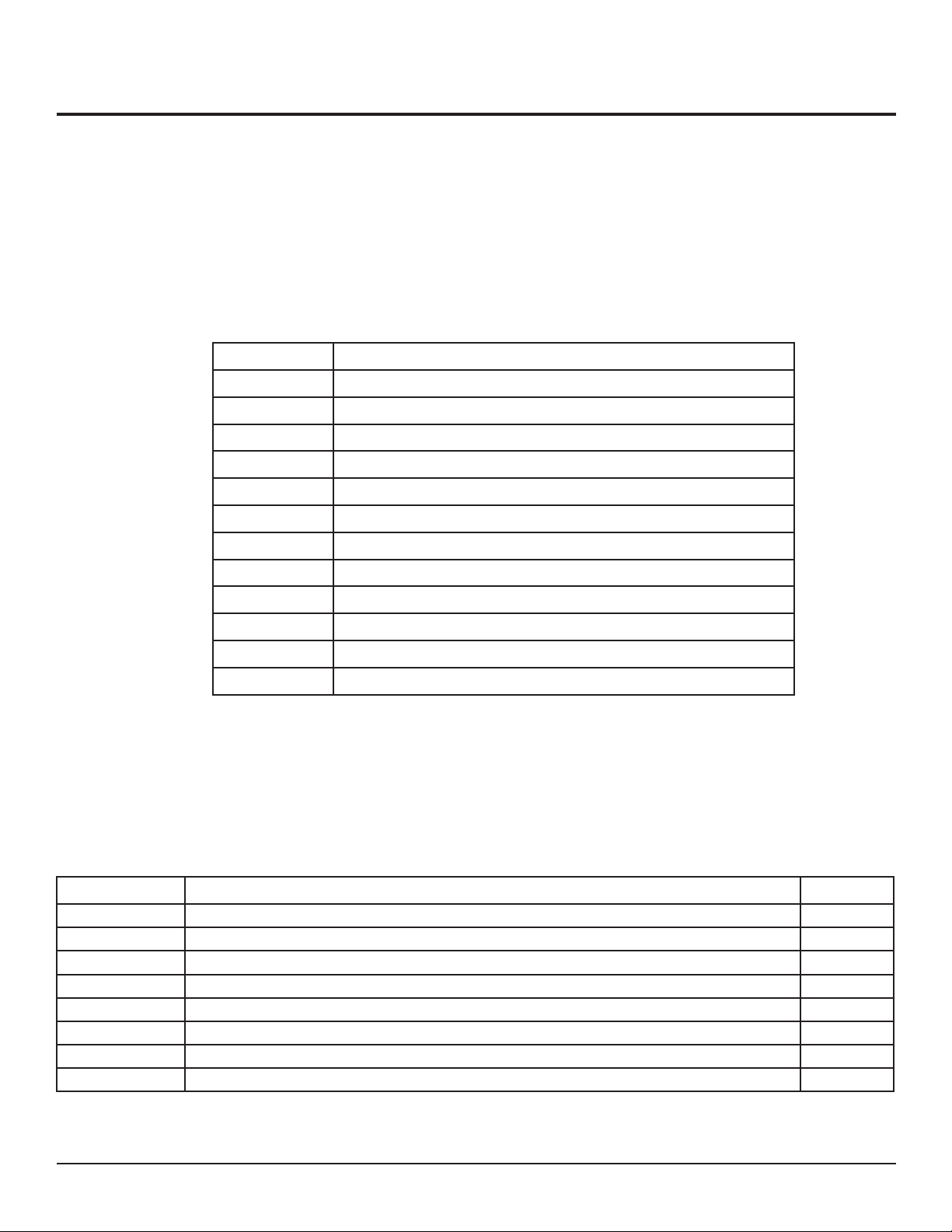
Diagnostic LED Flash Fault Descriptions
LED Display Description
ON No fault, normal conditions
OFF Internal controller fault
1 Flash Personality out of range
2 Flashes Illegal start condition (Traction)
3 Flashes MOSFET Short circuit
4 Flashes Contactor fault or motor open circuit
5 Flashes Motor stalled
6 Flashes Accelerator wire off fault
7 Flashes Low or high battery voltage or BDI cutout operating
8 Flashes Over temperature or timed cutback
9 Flashes Internal monitor function tripped / Maintenance required
10 Flashes Power up autozero has not been completed
Calibrator Fault Identifi cation Codes
In addition to the LED indication, a more detailed description of the fault may be found by using the
calibrator. Menu item 13.01 gives a fault identifi cation code which further defi nes the detected fault. The
following table lists the fault ID codes.
ID Code Fault Name Flash Fault
0 NO_FAULT LED_ON
1 UNIT_TOO_HOT 8
2 MONITOR_TRIPPED 11
3 I2T_CURRENT_LIMIT 8
4 MOTOR_TOO_HOT 12
5 MAINTENANCE_CLOSE_FAULT 9
6 ACCELERATOR_FAULT 6
7 ACCELERATOR_POWER_UP_FAULT 6
EUV Owner’s Manual 2 May 22, 2009
26
Page 27

Troubleshooting (cont’d)
Calibrator Fault Identifi cation Codes (cont’d)
ID Code Fault Name Flash Fault
7 BELLY_SWITCH_PRESSED 2
8 SEAT_FAULT 2
9 IDLE_FAULT 2
10 MAINTENANCE_FAULT 9
11 FS1_RECYCLE_FAULT 2
12 SRO_FAULT 2
13 TWO_DIRECTION_FAULT 2
14 SEQUENCE_FAULT 2
15 LOW_BATTERY_FAULT 7
16 HIGH_BATTERY_FAULT 7
17 HIGH_CAP_VOLTAGE_FAULT 7
18 MOTOR_STALL_DETECTED 5
19 HIGH_BATTERY_WITHOUT_LINE_FAULT 7
20 CONFIGURATION_RANGE_FAULT 1
21 CONFIGURATION_CRC_FAULT 1
22 LINE_CONTACTOR_WELDED 4
23 LINE_CONTACTOR_DID_NOT_CLOSE 4
24 NO_FAULT LED_ON
25 MOTOR_OPEN_CIRCUIT 4
26 ARMATURE_MOSFET_SHORT_CIRCUIT 3
27 VA_DETECT_FAIL LED_OFF
28 ARMATURE_MOSFETS_OFF LED_OFF
29 ARMATURE_MOSFETS_ON LED_OFF
30 ARMATURE_P_UP_MOSFET_SHORT_CIRCUIT 3
31 DRIVE_2_OFF LED_OFF
32 DRIVE_2_ON LED_OFF
33 DRIVE_1_OFF LED_OFF
34 DRIVE_1_ON LED_OFF
35 DRIVE_3_ON LED_OFF
36 DRIVE_3_OFF LED_OFF
37 AUTOZERO_NOT_VALID 10
EUV Owner’s Manual 2 May 22, 2009
27
Page 28

Warranty
Warranty Policy
PRODUCT REGISTRATION IS REQUIRED FOR WARRANTY COVERAGE.
To register your product, complete and return the enclosed warranty card to Wesley International. Wesley
International warrants to the original purchaser that their Pack Mule and Power Mule electric utility vehicles are free from defective factory material and workmanship. All warranties begin on the date of delivery
to the fi rst user. All warranty service must be approved by Wesley International prior to initiating
repairs.
Components, which fail under normal usage within the following specifi ed time periods and are proven
to be defective will be replaced by Wesley International without charge for parts unless stated otherwise
herein. Faulty components must be returned to Wesley International for inspection and warranty consideration.
Warranty Time Periods
Battery Charger: 2 years or 4,000 hours (whichever occurs fi rst)
•
Electronic throttle control: 2 years or 4,000 hours (whichever occurs fi rst)
•
Drive Motor: 1 year or 2,000 hours (whichever occurs fi rst)
•
DC Motor Controller: 1 year or 2,000 hours (whichever occurs fi rst)
•
Transaxle: 1 year or 2,000 hours (whichever occurs fi rst)
•
All other components except tires and batteries: 6 months or 1,000 hours (whichever occurs fi rst)
•
Batteries: Manufacturer’s limited warranty applies. Contact the local Exide battery distributor in
•
your area.
Tires are warranted against defects and workmanship by their manufacturer.
•
Warranty is void if:
The equipment is modifi ed or repaired in any manner not approved by Wesley International.
•
The vehicle is overloaded beyond its rated capacity.
•
The following are not covered under warranty:
Warranty service not authorized by Wesley International
•
Repairs to faulty components (Faulty components must be replaced and returned to Wesley
•
International for inspection.)
Adjustments, including initial fi eld set-up (Adjustments are considered part of normal
•
maintenance procedures.)
Purchaser’s labor costs or other charges for correcting defects or making additions
•
Repairs or service calls required as a result of:
•
Failure to follow maintenance, lubrication, or operational procedures specifi ed in the owner’s
-
manual
Abuse, willful damage, accident or neglect
-
Shipping damage (Such claims must be made with the freight carrier.)
-
Damage caused by using components or accessories not supplied or approved by
-
Wesley International
EUV Owner’s Manual 2 May 22, 2009
28
Page 29

Warranty (cont’d)
NOTICE OF LIABILITY
All other warranties or conditions, expressed or implied, including merchantability, fi tness for
a particular purpose or otherwise, are limited in duration to the expressed warranty period and
disclaimed in their entirety thereafter.
Wesley International’s obligation under this warranty is strictly and exclusively limited to the
replacement of defective parts. Wesley International does not assume or authorize anyone to assume
any other obligation.
Wesley International assumes no responsibility for incidental, consequential or other damages.
Wesley International
3680 Chestnut Street
Scottdale, Georgia 30079
Phone (404) 292-7441 • Toll Free (800) 241-2869 • Fax (404) 292-8469
www.WesleyInternational.com
EUV Owner’s Manual 2 May 22, 2009
29
Page 30

Notes
EUV Owner’s Manual 2 May 22, 2009
30
Page 31

Page 32

Wesley International
3680 Chestnut Street
Scottdale, Georgia 30079
Phone (404) 292-7441 • Toll Free (800) 241-2869 • Fax (404) 292-8469
www.WesleyInternational.com
 Loading...