

Page 1

SEPT 2013
OWNER’S MANUAL
AND SERVICE GUIDE
INDUSTRIAL ELECTRIC VEHICLE
Owner”s Manual and Service Guide – BCG Series
BCG-SERIES
Page 2

FOREWARD
NOTE
CAUTION
WARNING
A NOTE indicates a condition that should be observed.
A CAUTION indicates a condition that may result in damage to the vehicle.
A WARNING indicates a hazardous condition that could result in severe injury or death.
UPON RECEIPT OF VEHICLE/EQUIPMENT:
Please visually inspect the vehicle for any damage that may have occurred during shipping and have it noted on the
carrier’s bill immediately. Be sure to specify the nature of the damage.
This manual is a VERY IMPORTANT tool. Please keep it with the vehicle/equipment at all times. The purpose of this
manual is to provide owner, users, lessors and/or lessees with the operating instructions and precautions for the safe
and proper operation of the vehicle or equipment. It is the owner, user, lessor or lessees responsibility to ensure that
the vehicle/equipment is being used in accordance with its designed intended use.
Please read this ENTIRE manual to familiarize yourself with the safe operation of this vehicle/equipment. Pay
particular attention to anything labeled CAUTION, NOTE, OR WARNING!
Due to continuous product improvements, changes or updates may be made to this Manual, making it subject to
change without notice. For the most up to date version of the manual, please go to our website:
http://www.packmule.com/support/product-manuals/ OR call Wesley International at: 1-800-241-2869.
The Pack Mule Division of Wesley International, reserves the right to incorporate engineering and design changes to
products in this manual without any obligation to include these changes on any units/vehicles already purchased or
leased.
The Pack Mule Division and/or Wesley International accepts no liability in connection with any errors or omissions in
this Manual, and SPECIFICALLY DISCLAIMS any liability for any incidental and consequential damages arising from
the use of the information in this Manual.
The use of non OEM (Original Equipment Manufacturer) parts may void the warranty.
Overfilling the batteries may void your warranty.
The BCG tow vehicle is a Class VI Industrial Truck. Only operators trained per OSHA requirements shall operate this
vehicle.
NOTES, CAUTIONS AND WARNINGS
Throughout this guide NOTE, CAUTION, and WARNING will be used. Please observe these notes, cautions and warnings.
Owner’s Manual and Service Guide – BCG Series 2
Page 3

TABLE OF CONTENTS
INTRODUCTION ................................................................................................................................................................................ 5
SAFETY INFORMATION .................................................................................................................................................................... 6
Training ........................................................................................................................................................................................... 6
Operator Qualifications ................................................................................................................................................................... 6
Safety Guidelines ............................................................................................................................................................................ 6
Loading and Unloading ................................................................................................................................................................... 7
Towing ............................................................................................................................................................................................ 7
Maintenance ................................................................................................................................................................................... 7
Ventilation ................................................................ ................................ ....................................................................................... 7
INDUSTRY STANDARDS ................................................................................................................................................................. 8
OPERATING INSTRUCTIONS .............................................................................................................................................................. 12
Initial Checklist .............................................................................................................................................................................. 12
Identification.................................................................................................................................................................................. 12
Charging ....................................................................................................................................................................................... 12
Vehicle Controls, Meters, Switches .............................................................................................................................................. 12
Driving .......................................................................................................................................................................................... 17
Towing………………………………………………………………………………………………………………………………………....17
Coasting ....................................................................................................................................................................................... 17
Loading/Unloading ........................................................................................................................................................................ 17
Parking ......................................................................................................................................................................................... 17
Startup Checklist for Industrial Trucks………………………………………………………………………………………………………18
MAINTENANCE INSTRUCTIONS ......................................................................................................................................................... 19
Maintenance Schedule ................................................................................................................................................................. 19
Routine Maintenance .................................................................................................................................................................... 20
Batteries ....................................................................................................................................................................................... 20
Battery Safety………………………………………………………………………………………………………………………………….20
Battery Care.................................................................................................................................................................................. 20
Electrolyte Levels .......................................................................................................................................................................... 21
Battery Watering System .............................................................................................................................................................. 21
Cleaning Batteries ........................................................................................................................................................................ 21
Battery Replacement .................................................................................................................................................................... 21
Lifting the Vehicle ......................................................................................................................................................................... 22
Lubrication .................................................................................................................................................................................... 22
Brakes .......................................................................................................................................................................................... 23
Tires and Wheels .......................................................................................................................................................................... 23
COMPONENTS - ELECTRICAL ............................................................................................................................................................. 24
Basic Electrical Components ........................................................................................................................................................ 25
Special Order Onboard Battery Charger ....................................................................................................................................... 26
Motor ............................................................................................................................................................................................ 28
Controller ...................................................................................................................................................................................... 28
3 Owner’s Manual and Service Guide – BCG Series
Page 4

Battery Discharge Indicator (BDI) ................................................................................................................................................. 43
Speed Control Pedal ..................................................................................................................................................................... 43
Solenoid ........................................................................................................................................................................................ 43
Parts List – Electrical .................................................................................................................................................................... 44
Parts List – Available Options ..................................................................................................................................................... 455
COMPONENTS - MECHANICAL .......................................................................................................................................................... 46
Parts List – Front Wheel Steer Assembly ..................................................................................................................................... 46
Hitch Options…………………………………………………………………………………………………………………………………..47
Owner’s Manual and Service Guide – BCG Series 4
Page 5

INTRODUCTION
Thank you for choosing a Pack Mule Industrial Electric Vehicle, proudly built by Wesley International in the USA. At Wesley
International, we are committed to providing you the best quality product backed by exceptional customer service. This owner’s
manual and service guide is provided to help you get the most out of your new vehicle, for many years to come.
RECORD YOUR PRODUCT INFOR MATION
Model #: Serial #:
Purchase Date:
REGISTER YOUR PRODUCT
PRODUCT REGISTRATION IS REQUIRED FOR WARRANTY COVERAGE.
Registration is easy. Simply go to http://www.packmule.com/support/warranty/ and complete the online form and click submit.
That’s it! And it will entitle you to free parts for any defective items, as outlined in our warranty document.
IF YOU NEED HELP
You will find many answers to common problems within this manual or online at www.packmule.com. If you do not find
what you need, we are always ready and willing to help. Just email us at [email protected] or call
(800) 241-2869 or (404) 292-7441.
Wesley International
3680 Chestnut Street
Scottdale, GA 30079
Phone (404) 292-7441 • Toll Free (800) 241-2869 • Fax (404) 292-8469
www.wesleyinternational.com
5 Owner’s Manual and Service Guide – BCG Series
Page 6

SAFETY INFORMATION
The responsibility of safety lies with four main groups: manufacturers, owners/lessees, operators and maintenance personnel.
This manual has been designed to assist the owner-operator in operating and maintaining the vehicle in a safe manner, in
accordance with the procedures and standards to which the vehicle was designed and intended for use.
TRAINING
Vehicle owners/lessees are responsible for instructing their personnel in its safe operation. Owner/lessees must explain the
vehicle’s characteristics, features, operation of its controls, and safe driving practices. We strongly recommend that
owners/lessees first become familiar with the conditions of the place where the vehicle will be operated in order to assess its effect
on safe operation. Training should occur under the conditions of the operating environment while adhering to the safety guidelines
and include:
Safety guidelines
Operation of the vehicle under the conditions in which it will be operated
Operation of all controls
Safe driving practices
A driving and operating test
OPER ATOR QUALIFICATIONS
Operators should be selected based on their ability to safely operate the vehicle, including vision, hearing, physical and mental
capabilities. Operators must:
Demonstrate a working knowledge of all controls
Understand all safety guidelines
Be evaluated by a designated trainer who certifies the operator’s ability to properly drive and park the vehicle under the
conditions in which the vehicle will be used
Know how to properly load and unload cargo and passengers
Recognize maintenance problems
SAFETY GUIDELINES
All Pack Mule vehicles are designed for use on smooth surfaces in and around industrial plants and warehouses. Not intended for
agricultural use. While made of components that are unaffected by the rain, they are not intended for continuous outdoor use,
traversing up and down steep grades, or travelling on public roads/highways as the tires are not configured for these purposes.
Follow these guidelines to safely drive the vehicle:
Read, understand and observe all labels affixed to the vehicle
Do not start the vehicle without checking the brakes first
Do not mount or dismount the vehicle when the key is in the ON position
Do not drive the vehicle if the accelerator requires excessive pressure
Do not park or operate the vehicle near flammable objects or in a flammable or hazardous environment
Use only necessary power
Keep both hands on the steering wheel while operating the vehicle
Accelerate and decelerate slowly and in a controlled manner
Always reduce speed to compensate for poor terrain or conditions
Always maintain adequate distance between vehicles, people, and obstacles
Do not use the vehicle to push objects
Do not allow the tires to lose contact with the ground
Proceed around low overhangs with caution. Be sure there is enough clearance for the operator’s head and the highest
point of the vehicle or any attached accessories.
Never abruptly change direction
Always drive directly up an incline; never across
Never exceed the designated passenger, load or towing capacity
On grades, it is possible for vehicles to coast at greater than normal speeds encountered on a flat surface. To prevent loss of
vehicle control and possible serious injury, speeds should be limited to no more than maximum speed on level ground.
.
Owner’s Manual and Service Guide – BCG Series 6
Page 7

WARNING
WARNING
SAFETY INFORMATION
Good common sense and prudent driving practices do more to prevent accidents and injuries than all of the warnings and
instructions combined. Wesley International strongly suggests that the owner-operator read this entire manual paying particular
attention to the CAUTIONS and WARNINGS contained therein
Loading and Unloading
Follow these guidelines when loading and unloading cargo from the vehicle or trailers:
Turn the vehicle off while loading
Do not exceed the maximum passenger or cargo load capacity
Carefully and evenly position all loads
Secure cargo so that nothing can easily fall off of the vehicle or trailer
Be extremely careful carrying loads that extend beyond the vehicle’s deck
TOWING
Follow these guidelines when towing:
Turn the vehicle off when connecting equipment that will be towed
Always use a properly installed hitch that matches the trailer tongue (Optional hitches available from Wesley International)
Do not exceed the maximum towing capacity
Do not exceed 5 mph when towing
Take extreme care when towing down an incline. Do not tow trailers down an incline with a grade of more than 15%.
MAINTENANCE
Always maintain your vehicle in accordance with the service schedule within this manual and keep complete records of the
maintenance history of the vehicle. Ensure the maintenance personnel performing any service or repair work on the vehicle are
trained and qualified to do so. Be sure to disable the vehicle before performing any maintenance including removing the key from
the key switch and removal of a battery cable.
Always insulate any tools used within the battery area in order to prevent sparks or battery
explosion caused by shorting the battery terminals or associated wiring.
Be sure to check the polarity of each battery terminal and be sure to rewire the batteries correctly. Never install a wire instead of a
proper fuse, even for a temporary fix. It may cause extensive damage and possible fire. Do not use a screwdriver or other metal
object to remove fuses. Doing so may cause an electrical short and damage the system. Do not modify or tamper with any part of
the operating or speed control systems. All inspections and adjustments must be made by a qualified technician.
Always support the vehicle using wheel chocks and safety stands. Never get under a vehicle that is supported by a jack. Lift the
vehicle in accordance with the instructions in this manual.
Always test drive the vehicle after any repairs or maintenance in a safe area free of any other vehicles or pedestrians.
VENTILATIO N
Hydrogen gas is generated in the charging cycle of batteries and is explosive in concentrations
as low as 4%. Because hydrogen gas is lighter than air, it will collect in the ceilings of buildings
and therefore, proper ventilation is required. Five air exchanges per hour is considered the
minimum ventilation required.
Always use a dedicated circuit for each battery charger. Do not permit other appliances to be plugged into the receptacle when the
charger is in operation.
7 Owner’s Manual and Service Guide – BCG Series
Page 8

INDUSTRY STANDARDS
The following text is provided as recommended by Part II,
“For the User”, of ANSI/ITSDF B56.8-2011, Safety Standard
for Personnel and Burden Carriers. The manufacturer
strongly endorses the contents of this specification.
6 GENERAL SAFETY PRACTICES
6.1 Introduction
6.1.1 Like other machines, carriers can cause injury if
improperly used or maintained. Part II contains broad safety
practices applicable to carrier operation. Before operation,
the user shall establish such additional specific safety
practices as may reasonably be required for safe operation.
6.1.2 Premise review — The user shall periodically
review their premises, and as conditions warrant, identify
areas where carriers should not be operated and to identify
possible hazards such as the following examples:
(a) Steep Grade — In areas where steep grades exist,
carrier operation should be restricted to the designated
vehicle’s pathways where possible, and shall be identified
with a suitable warning giving the following information:
“Warning, steep grade.”
(b) Wet Areas — Wet areas could cause a carrier to lose
traction and could affect steering, stability and braking.
(c) Sharp Turns, Blind Spots, Bridge Approaches —
Sharp turns, blind spots, bridge approaches, and other
potentially hazardous areas shall be identified with a suitable
warning to the operator of the nature of the hazard and
stating the proper precautions to be taken to avoid the
hazard.
(d) Loose Terrain — Loose terrain could cause a carrier
to lose traction and could affect steering, stability, and
braking.
6.2 Operation
Experience has shown that carriers, which comply with the
provisions, stated in paragraphs 9.4, 9.5, and 9.6 are stable
when properly operated and when operated in accordance
with specific safety rules and practices established to meet
actual operating terrain and conditions. However, improper
operation, faulty maintenance, or poor housekeeping may
contribute to a condition of instability and defeat the purpose
of the standard. Some of the conditions which may affect
stability are failure of the user to follow safety practices; also,
ground and floor conditions, grade, speed, loading, the
operation of the carrier with improper loads, battery weight,
dynamic and static forces, and the judgment exercised by
the carrier operator.
(a) The user shall train carrier operators to adhere
strictly to the operating instructions stated in this Standard.
(b) The user shall survey specific operating conditions
and environment, and establish and train carrier operators to
comply with additional, specific safety practices.
6.3 Nameplates, Markings, Capacity, and Modifications
6.3.1 The user shall maintain in a legible condition all
nameplates, warnings, and instructions, which are supplied
by the manufacturer.
6.3.2 Except as provided in 6.3.4, no modifications or
alterations to a carrier, which may affect the capacity,
stability, or safe operation of the carrier, shall be made
without the prior written approval of the original carrier
manufacturer or a successor thereof. When the carrier
manufacturer or its successor approves a modification or
alteration, appropriate changes shall be made to capacity
plates, decals, tags, and operation and maintenance
manuals.
6.3.3 As required under paragraphs 6.3.1 or 6.3.2, the
manufacturer shall be contacted to secure new nameplates,
warnings, or instructions, which shall then be affixed in their
proper place on the carrier.
6.3.4 In the event that the carrier manufacturer is no
longer in business and there is no successor in interest to
the business, the user may arrange for a modification or
alteration to a carrier, provided however, the controlling party
shall:
(1) Arrange for the modification or alteration to be
designed, tested, and implemented by an engineer(s) expert
in carrier(s) and their safety;
(2) Maintain a permanent record of the design, test(s),
and implementation of the modification or alteration;
(3) Make appropriate changes to the capacity plate(s),
decals, tags, and operation and maintenance manuals;
(4) Affix a permanent and readily visible label on the
carrier stating the manner in which the carrier has been
modified or altered together with the date of the modification
or alteration, and the name of the organization that
accomplished the tasks.
6.4 Changing and Charging Storage Batteries for
Electric Personnel and Burden Carriers
6.4.1 The user shall require battery changing and
charging facilities and procedures to be in accordance with
ANSI/NFPA 505 or as required by local ordinance.
6.4.2 The user shall periodically inspect facilities and
review procedures to be certain that ANSI/NFPA 505 or as
required by local ordinance, are strictly complied with, and
shall familiarize carrier operators with it.
Owner’s Manual and Service Guide – BCG Series 8
Page 9

INDUSTRY STANDARDS
6.4.3 Maintenance and storage areas for carriers shall be
properly ventilated to avoid fire hazards in accordance with
applicable fire codes and ordinances.
Ventilation for internal combustion engine powered carriers
shall be provided to remove flammable vapors (gases),
fumes and other flammable materials. Consult applicable fire
codes for specific levels of ventilation.
Ventilation for electric powered carriers shall be provided to
remove the accumulation of flammable hydrogen gas
emitted during the battery charging process.
The amount of hydrogen gas emitted depends upon a
number of factors such as the condition of the batteries, the
output rate of the battery charger and the amount of time the
batteries are on charge. Because of the highly volatile nature
of hydrogen gas and its propensity to accumulate in pockets,
a minimum number of air changes per hour is required
during charging.
Consult applicable fire and safety codes for the specific
ventilation levels required as well as the use of explosion
proof electrical apparatus. SAE J1718 can be followed to
check for hydrogen gas levels.
6.5 Hazardous Locations
6.5.1 The user shall determine the hazard classification
of the particular atmosphere or location in which the carrier
is to be use in the accordance with ANSI/NFPA 505.
6.5.2 The user shall permit in hazardous areas only those
carriers approved and of the type required by ANSI/NFPA
505.
6.6 Lighting for Operating Area
The user, in accordance with his responsibility to survey the
environment and operating conditions, shall determine if the
carrier requires lights and, if so, shall equip the carrier with
appropriate lights.
6.7 Control of Noxious Gases and Fumes
When equipment powered by internal combustion engines is
used in enclosed areas, the atmosphere shall be maintained
within limits specified in the American Conference of
Governmental Industrial Hygienists publication, “Threshold
Limit Values for Chemical Substances and Physical Agents
in the Workroom Environment.” This may be accomplished
by ventilation provided by the user, or the installation, use,
and proper maintenance of emission control equipment
recommended or provided by the manufacturer of the
equipment.
6.8 Warning Device(s)
6.8.1 The user shall make periodic inspections of the
carrier to be certain that the sound-producing and/or visual
device(s) if so equipped are maintained in good operating
condition.
6.8.2 The user shall determine if operating conditions
require the carrier to be equipped with additional sound
producing or visual devices or both and be responsible for
providing and maintaining such devices, in accordance with
the manufacturer’s recommendations.
6.9 Safety Interlocks
The user shall make periodic inspections of the carrier to be
certain that the safety interlock system, if so equipped, is
operating properly.
7 OPERATING SAFETY RULES AND PRACTICES
7.1 Personnel and Burden Carrier Operator
Qualifications
Only persons who are trained in the proper operation of the
carrier shall be authorized to operate the carrier. Operators
shall be qualified as to visual, auditory, physical, and mental
ability to safely operate the equipment according to Section
7, all other applicable parts of this Standard and the
operators’ manual.
7.2 Personnel and Burden Carrier Operators’ Training
7.2.1 The user shall conduct an operators’ training
program.
7.2.2 Successful completion of the operators’ training
program by the operator shall be required before operation
of the carrier. The program shall be presented in its entirely
to all-new operators and not condensed for those claiming
previous experience.
7.2.3 The user shall include as a minimum in the
operators’ training program the following:
(a) Instructional material provided by the manufacturer
including the operators’ manual;
(b) Emphasis on safety of passengers, material loads,
carrier operator, and other person(s);
(c) General safety rules contained within this Standard
and the additional specific rules determined by the user in
accordance with this Standard, and why they were
formulated;
(d) Introduction of equipment, control locations and
functions, and explanation of how they work when used
properly and when used improperly; and surface conditions,
grade, and other conditions of the environment which could
affect carrier operation;
(e) Operator competency evaluations.
9 Owner’s Manual and Service Guide – BCG Series
Page 10

INDUSTRY STANDARDS
7.3 Personnel and Burden Carrier Operator
Responsibility
7.3.1 General Operator Responsibility
7.3.1.1 Read and follow operators’ manual.
7.3.1.2 Do not operate carrier under the influence of drugs
and alcohol.
7.3.1.3 Safeguard the pedestrians at all times. Do not drive
carrier in a manner that would endanger other persons.
7.3.1.4 Riding on the carrier by persons other than the
operator is authorized only on personnel seat(s) provided by
the manufacturer. All parts of each person’s body shall
remain within the plan view outline of the carrier.
7.3.1.5 When a carrier is to be left unattended, stop the
carrier, apply the parking brake, stop the engine or turn off
power, turn off the control or ignition circuit, and remove the
key if provided. Additionally, for electric carriers, the forward
and reverse directional controls, should be neutralized if a
means is provided. Block the wheels if the carrier is on an
incline.
7.3.1.6 A carrier is considered unattended when the
operator is 7.6m (25 ft) or more from the carrier which
remains in his view, or whenever the operator leaves the
carrier and it is not within his view. When the operator is
dismounted and within 7.6m (25 ft) of the carrier still in his
view, he still must have controls neutralized, and the parking
brake(s) set to prevent movement.
7.3.1.7 Maintain a safe distance from potential hazards,
such as edges of ramps and platforms.
7.3.1.8 Use only approved carriers in hazardous locations,
as defined in the appropriate safety standards.
7.3.1.9 Report all accidents to the user.
7.3.1.10 Do not add to, or modify, the carrier.
7.3.1.11 Carriers shall not be parked or left unattended
such that they block or obstruct fire aisles, access to
stairways, or fire equipment.
7.3.1.12 Only operate carrier while within operator’s
station.
7.3.2 Traveling
7.3.2.1 Observe all traffic regulations, including authorized
speed limits. Under normal traffic conditions keep to the
right. Maintain a safe distance, based on speed of travel,
from a carrier or vehicle ahead; and keep the carrier under
control at all times.
7.3.2.2 Yield the right of way to pedestrians, ambulances,
fire trucks, or other carriers/vehicles in emergency situations.
7.3.2.3 Do not pass another carrier or vehicle traveling in
the same direction at intersections, blind spots, or at other
dangerous locations.
7.3.2.4 Keep a clear view of the path of travel, observe
other traffic and personnel, and maintain a safe clearance.
7.3.2.5 Slow down or stop, as conditions dictate, and
activate the sound-producing warning device at cross aisles
and when visibility is obstructed at other locations.
7.3.2.6 Ascend or descend grades slowly.
7.3.2.7 Avoid turning, if possible, and use extreme caution
on grades, ramps, or inclines; normally travel straight up and
down.
7.3.2.8 Under all travel conditions the carrier shall be
operated at a speed that will permit it to be brought to a stop
in a safe manner.
7.3.2.9 Make starts, stops, turns, or direction reversals in a
smooth manner so as not to shift the load, endanger
passengers, or lose control of the carrier.
7.3.2.10 Do not operate carrier in a dangerous manner.
7.3.2.11 Slow down when approaching, or on, wet or
slippery surfaces.
7.3.2.12 Do not drive carrier onto any elevator unless
specifically authorized to do so. Approach elevators slowly,
and then enter squarely after the elevator car is properly
leveled. Once on the elevator, neutralize the controls, shut
off power, and set parking brakes. It is advisable that all
other personnel leave the elevator before a carrier is allowed
to enter or exit.
7.3.2.13 Avoid running over loose objects, potholes, and
bumps.
7.3.2.14 Reduce carrier speed to negotiate turns.
7.3.2.15 Avoid any action verbal or physical by an operator
or passenger, which could cause the operator to be
distracted.
7.3.3 Loading
7.3.3.1 Refer to operators’ manual for loading instruction.
7.3.3.2 Handle only stable and safely arranged loads.
When handling off-center loads, which cannot be centered,
operate with extra caution.
7.3.3.3 Handle only loads within the capacity of each cargo
area of the carrier as specified by the manufacturer.
7.3.3.4 Avoid material loads exceeding the physical
dimensions of the carrier or as specified by the carrier
manufacturer.
Owner’s Manual and Service Guide – BCG Series 10
Page 11

INDUSTRY STANDARDS
7.3.4 Operator Care of Personnel and Burden
Carriers
7.3.4.1 Read and follow operators’ manual.
7.3.4.2 At the beginning of each shift during which the
carrier will be used, the operator shall check the carrier
condition and inspect the tires, warning devices, lights,
battery(s), speed and directional controllers, brakes, safety
interlocks, and steering mechanism. If the carrier is found to
be in need of repair or is in any way unsafe, the matter shall
be reported immediately to the user and the carrier shall not
be operated until restored to safe operating condition.
7.3.4.3 If during operation the carrier becomes unsafe in
any way, the matter shall be reported immediately to the
user, and the carrier shall not be operated until it has been
restored to safe operating condition.
7.3.4.4 Do not make repairs or adjustments unless
specifically trained and authorized to do so.
7.3.4.5 Before refueling, the engine shall be stopped and
allowed to cool. The operator and passengers shall leave
the carrier before refueling.
7.3.4.6 Spillage of hazardous materials shall be contained
immediately and addressed via appropriate hazardous
materials regulations.
7.3.4.7 Do not operate a carrier with a leak in the fuel
system or battery(s). Battery(s) shall be charged and
serviced per manufacturer’s instructions.
7.3.4.8 Do not use open flames for checking electrolyte
level in storage battery(s) or liquid level in fuel tanks.
8 MAINTENANCE PRACTICES
8.1 Introduction
Carriers may become hazardous if maintenance is
neglected. Maintenance facilities, trained personnel, and
procedures shall be provided. Such facilities may be on or
off the premises.
8.2 Maintenance Procedures
Maintenance and inspection of all carriers shall be
performed in conformance with the following practices and
should follow the manufacturer’s recommendations.
(a) A scheduled preventive maintenance, lubrication,
and inspection system shall be followed.
(b) Only trained and authorized personnel shall be
permitted to maintain, repair, adjust, and inspect carriers.
(c) Before undertaking maintenance or repair, follow the
manufacturer’s recommendations for immobilizing the
carrier.
(d) Chock wheels and support carrier, before working
underneath it.
(e) Before disconnecting any part of the engine fuel
system, be sure the shutoff valve, if so equipped, is closed
and follow carrier manufacturer’s recommended practice.
(f) Operation to check performance of the carrier shall be
conducted in an authorized area where suitable conditions
exist, free of vehicular and pedestrian traffic.
(g) Before returning carrier to service, follow the
manufacturer’s instructions and recommended procedures.
(h) Avoid fire hazards and have fire protection equipment
present in the work area. Do not use an open flame to check
level or leakage of fuel, battery electrolyte, or coolant.
(i) Properly ventilate the work area in accordance with
applicable regulations or local ordinance.
(j) Handle fuel cylinders with care. Physical damage,
such as dents, scrapes, or gouges, may dangerously
weaken the tank and make it unsafe for use.
(k) Brakes, steering mechanisms, speed and directional
control mechanisms, warning devices, lights, governors,
guards, and safety devices shall be inspected regularly and
maintained in accordance with manufacturer’s
recommendations.
(l) Carriers or devices designed and approved for
hazardous area operation shall be inspected to ensure that
maintenance preserves the original approved safe operating
features.
(m) Fuel systems shall be checked for leaks and
condition of parts. If a leak is found, action shall be taken to
prevent the use of the carrier until the cause of the leak has
been repaired.
(n) The carrier manufacturer’s capacity, operation, and
maintenance instruction plated, tags, or decals shall be
maintained in legible condition.
(o) Batteries, motors, speed and directional controllers,
limit-switches ,protective-devices ,electrical
conductors/insulators, and connections shall be inspected
and maintained per carrier manufacturer’s recommendation.
(p) Carriers shall be kept clean to minimize hazards and
facilitate detection of components needing service
(q) Modifications and additions which affect capacity and
safe carrier operation shall not be performed without
manufacturer’s prior written authorization; where authorized
modifications have been made, the user shall ensure that
capacity, operation, warning, and maintenance instruction
plates, tags, or safety labels are changed accordingly.
(r) Care shall be taken to ensure that all replacement
parts are interchangeable with the original parts and of a
quality at least equal to that provided in the original
equipment.
(s) Disconnect batteries, negative connection(s) first.
When reconnecting, connect positive connection first.
(t) Hydraulic systems, if so equipped, shall be checked
for leaks, for condition of parts. Keep body and hands away
from pin-holes or nozzles that eject fluids under high
pressure. Use paper or cardboard, not hands, to check for
leaks.
11 Owner’s Manual and Service Guide – BCG Series
Page 12
OPERATING INSTRUCTIONS
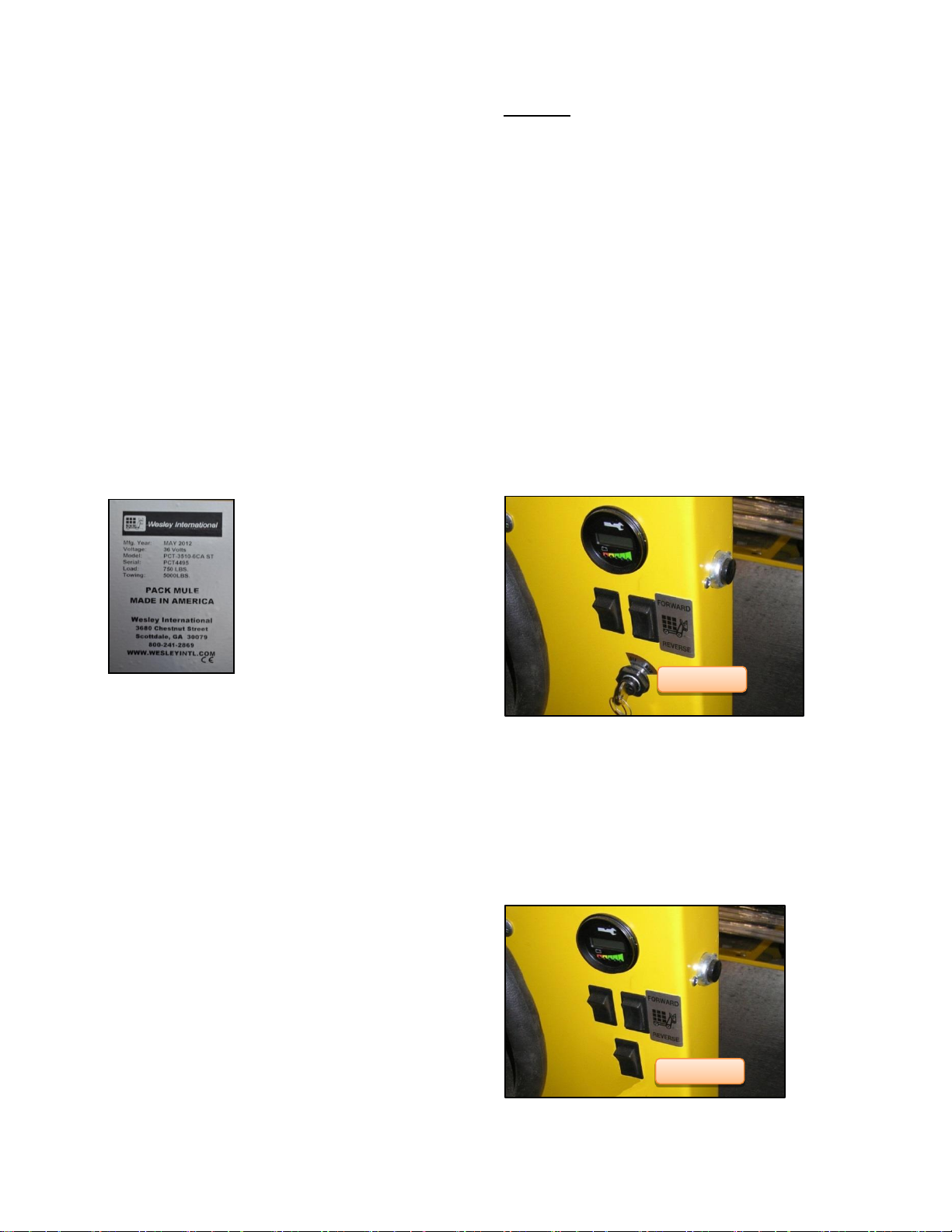
On/Off Switch
FIGURE 1
Key Switch
INITIAL CHECK LIST
Use the following checklist to inspect and prep your vehicle
prior to initial use.
□ Check for evidence of leaking fluids, i.e. battery acid, or
gear oil.
□ Check condition of tires and tire air pressure. Maximum
90 psi Cold; 60 psi recommended. (Pneumatic tires
only).
□ Check to ensure wheel lug nuts are tight.
□ Check that all battery connections are tight/corrosion
free
□ Check for smooth operation of controls, switches, and
brakes.
□ Charge batteries.
IDEN TIFICATION
The product model number, serial number, and year of
manufacture is located on a
silver label ( Figure 1), either on
the front of the vehicle near the
switches, on the underside of
the plate where the seat is
mounted, or inside the motor
compartment attached to a side
panel.
Whenever you correspond with
Wesley International regarding
your vehicle, be sure to include
this information.
CHAR GIN G BATTERIES
The BCG Series electric vehicles come standard with an
Industrial battery. Industrial batteries are charged with rapid
chargers that normally are hard wired into the plant electrical
system. No onboard charger is provided. However, we will
accept special orders that include an onboard charger.
When charging, follow these steps to charge the battery:
1) Position the vehicle within reach of the external
charger cord.
2) Slide seat to the rear most position and tilt forward to
open battery compartment.
3) Check all battery cells for proper acid level. Fluid
should be above plates
4) Unplug the battery from the vehicle and plug it into
the externally mounted charger using the cord from the
external charger.
CAUTION: Onboard chargers require extension cords that
are 3-wire cord no longer than 30m (100’) at 10AWG or 7.5m
(25’) at 16 AWG per UL guidelines. Only connect ONE
onboard charger to a single 15A circuit or the circuit may
become overloaded.
VEHICLE CO NTR OLS, METERS, SWITCHES
The controls, meters and switches consist of:
Key Switch, Perma-Key Switch, or On/Off Switch
FWD/REV Directional Selector Switch
Battery Discharge Indicator (BDI)
Headlight / Tail Light Switch (Optional)
Parking Brake
Speed Control Pedal
Brake Pedal
Horn Button
Seat Presence Sensor Switch
Foot Presence Switch (Optional)
Key Switch: For vehicles equipped with a key switch (Figure
2), the vehicle only operates when the key is in the switch. It
has two positions – run and off.
FIGURE 2
Perma-Key Switch (Optional): An optional Perma-Key
switch is available to replace the standard key switch. It
works the same way, but eliminates the need for a separate
key that may get lost. It has three positions – run, off, and
charge only.
On/Off Rocker Switch (Optional): An optional 2 position
on/off Rocker switch is available to replace the standard key
switch. (Figure 3).
Owner’s Manual and Service Guide – BCG Series 12
.
FIGURE 3
Page 13

WARNING
OPERATING INSTRUCTIONS
FIGURE 4
To prevent unexpected vehicle movement or
unauthorized use, always turn the key switch to the OFF
position and remove key when the vehicle is not in use
Programmable Security Switch (Optional): SAFE-T-
LOCK™ is a programmable code switch,( Figure 4), which
prevents unauthorized use of the vehicle. It is offered as an
option, part number EVE901. The SAFE-T-LOCK
switch is installed in lieu of
the standard switch to
control access and
operation of the vehicle
within the customer’s
premises. It can be preinstalled at time of order, or
purchased separately to
upgrade existing vehicles.
The STL1000 switch allows
plant and facility managers
to input up to 99 different users/drivers to track vehicle
usage. If an accident occurs, or the vehicle is damaged, the
manager can easily identify the last operator. The switch
also features an internal clock that records "on" hours and
notifies the operator when the 250-hour mark is reached.
Each user can select a four- to eight-digit personal access
code and a separate supervisor user menu programs the
unit. The switch will provide the last user ID code when
prompted by the supervisor. In operation, only users with
active ID codes can operate the vehicle, virtually eliminating
all unauthorized use, the company said.
The switch operates in a voltage range from 9 to 120 volts
DC and is enclosed in an IP65 rated housing. Two internal
LEDs indicate operational status - red indicates an error or
lock mode and green indicates key press or touch is active.
The unit also provides user feedback with key beep and
error tones.
Step-by-Step Programming Instructions:
1 – Log onto the Supervisor Mode. Press 0 0 1 2 3 4
ENTER. Red and Green LED flashes along with an up tone
beep indicate you are in the Supervisor Mode and ready to
enter a Supervisor Mode menu.
Note: As you enter each Supervisor Mode menu, the number
of Red LED flashes will correspond to the menu number. For
example, one Red LED flash for menu 1, two Red LED
flashes for menu 2, etc.
Before changing the Supervisor PIN, you are first going to
add User locations. For this example you will check on and
add User location 01 as well as more User locations as
required. To do this you must go into the Add / Delete User
Menu.
2 – Go into Add / Delete User Menu. Press 2 ENTER. There
will be a beep along with two Red LED flashes indicating you
are in Menu 2. Press 0 1 ENTER. If there is a Red flash and
a low beep, it indicates that user location 01 has already
been assigned. To remove location 01, press ENTER again.
This will delete the location from use.
Add location 01. Press 0 1 ENTER. You should now get a
Green flash along with an up tone beep indicating the
location is ready to be added or assigned to a user. Press
ENTER. You will get a Green LED flash along with a beep.
The user location has been added.
At this point you can, in the same way, check on and add
more user locations.
Before leaving Menu 2, check to make sure that location 01
and any others have been added. Press 0 1 ENTER. There
should be a Red LED flash along with a low tone beep
indicating the location has been assigned to the user. Check
any other locations you’ve added the same way. A Red flash
along with a low tone beep means the location has been
assigned. A Green flash along with an up tone beep means
the location is not assigned.
3 – Go out of Menu 2. Press CE. The switch will indicate you
are back in Supervisor Mode. Press CE again to go out of
Supervisor Mode. (CE can be pressed several times to make
sure you are completely clear and ready to enter the next
mode.)
4 – Log onto the User Mode. Press 0 1 1 2 3 4 ENTER. The
switch will close and the Green LED will flash at a slow rate.
5 – Change User PIN. First decide on a new PIN. In this
example
e use 5 4 3 2 1. Press 1, ENTER. (This puts you in the
Change User PIN Menu.) Note that the switch will open
when you go into this menu.
Note: The User has 1 minute after logging on the User Mode
to use menu 1 before the menu function is locked out until
the next User log on.
Press 5 4 3 2 1 ENTER, again press 5 4 3 2 1 ENTER. The
switch will indicate that the new PIN has been accepted.
6 – Use the new PIN to close the switch. Press 0 1 5 4 3 2 1
ENTER. The switch will close. Press ENTER to open the
switch and go out of User Mode. (Since this is an example,
you may want to set the PIN for User location 01 back to the
1 2 3 4 default.)
7 – Log back onto the Supervisor Mode to change the
Supervisor PIN. Press 0 0 1 2 3 4 ENTER. Press 1 ENTER
to go into the Change Supervisor PIN Menu. The red LED
will flash once. Now just you did in the User Mode, put the
new PIN in twice and enter each time. Example: Press 5 4 3
2 1 ENTER, again 5 4 3 2 1 ENTER. The switch will give an
indication that the PIN was changed.
13 Owner’s Manual and Service Guide – BCG Series
Page 14
WARNING
NOTE
OPERATING INSTRUCTIONS
Directional Switch
8 – Go out of Menu 1. Press CE. Press CE again to Log Off
the Supervisor Mode.
9 – Check out the new Supervisor PIN. Press 0 0 5 4 3 2 1
ENTER. You should be in Supervisor Mode. You can now go
to any menu by pressing the menu number and ENTER.
Remember: This is an example. You should change your
Supervisor PIN to one known only to you.
10 – Determine Last user. While in Supervisor Mode press 3
ENTER. This places you in the Last User Menu as indicated
by three red LED flashes. Press ENTER again. The LED
flashes will indicate the last user. The Green LED is for the
10’s digit. The Red LED is for the 1’s digit. Example 1: A
single Red LED flash indicates User 01 last operated the
vehicle. Example 2: Two Green flashes and three Red
flashes would indicate User 23 last operated the vehicle.
Press CE to leave the menu.
11 – Enable or Disable Maintenance Alarm. Press 4 ENTER.
There will be four red LED flashes. Press ENTER again. If
the Green LED flashes, the alarm is enabled. Press ENTER
again and the Red LED will flash showing the alarm to be
disabled. Press ENTER again and the Green LED will flash
showing the alarm to be again enabled.
12 – Listen to the maintenance alarm. While in Menu 4 press
1 ENTER. The maintenance alarm will sound. Press CE to
leave the menu. Press CE again to Log Off the Supervisor
Mode.
Note: If the switch is left unattended in Supervisor mode, it
will automatically exit the mode after approximately one
minute.
13 – If you are unable to get into the Supervisor mode after
trying either the default PIN or a newly assigned PIN, go
back to Step 1 and reset the switch.
If all else fails or if you have questions about programming or
installing the SAFE-T-LOCK, call Tech Support at 1-800241-2869.
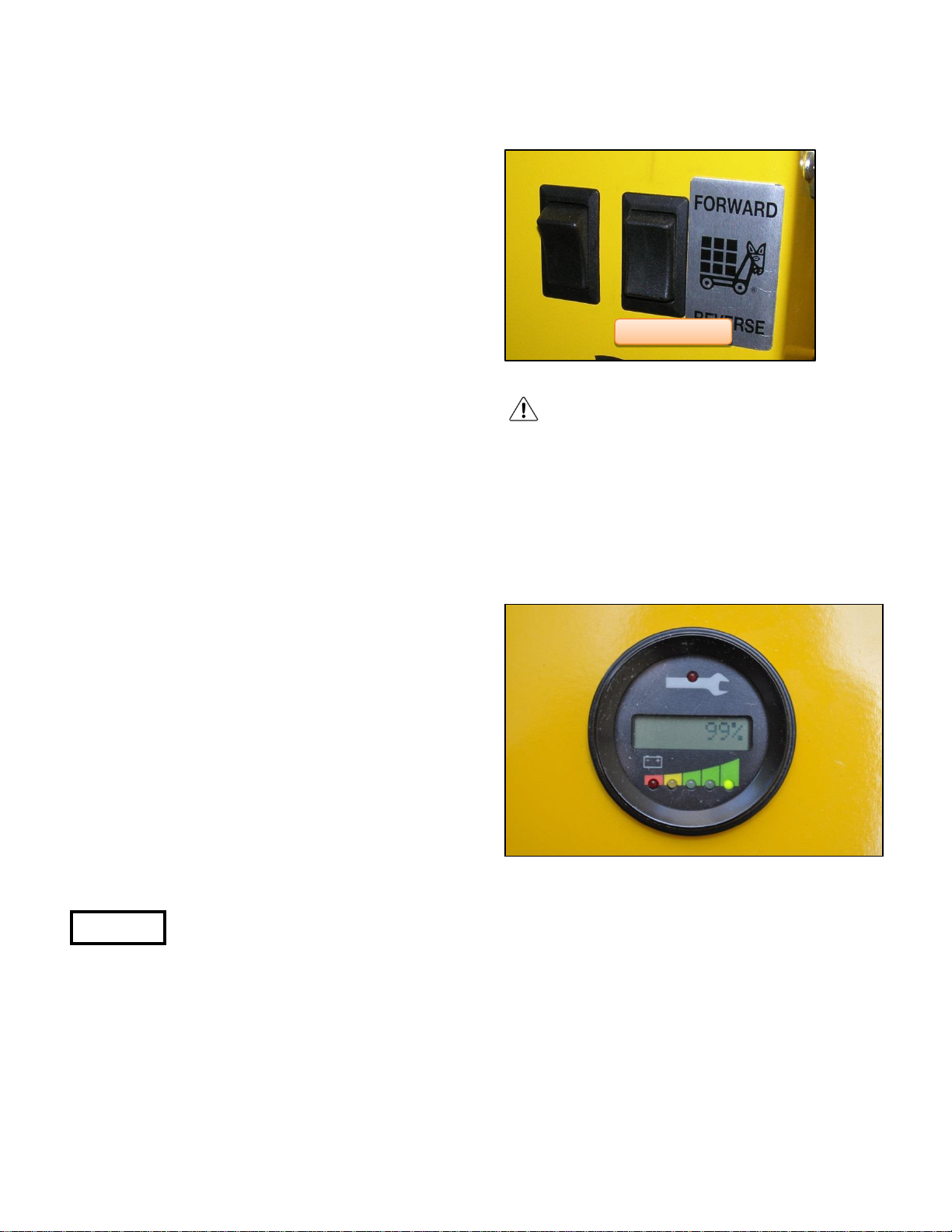
Directional Switch: The directional rocker or toggle switch
is used to place the vehicle in one of three operating modes
– forward, reverse, or neutral. (Figure 5) shows a rocker
directional switch.
The directional switch MUST be in
NEUTRAL (center) position BEFORE
selecting vehicle “ON” or a “Static Return
to Off” (SRO) error code will be generated by the motor
controller. The vehicle is temporarily immobilized as a
standard safety feature. (If your vehicle is equipped with the
Optional Foot Presence Switch and the unit is already turned
on and in neutral position, the foot presence switch MUST
be engaged before the directional switch is placed in forward
or reverse mode, or the same error code will be displayed
and the vehicle temporarily immobilized.) If this error code is
displayed, return the directional switch back to neutral,
ensure the foot presence switch is engaged, and then switch
the directional Switch to the desired forward or reverse
position and the vehicle will operate.
FIGURE 5
To prevent unexpected vehicle
movement, always place the
directional switch in the
NEUTRAL position when
leaving the vehicle.
Battery Discharge Indicator (BDI): The battery discharge
indicator, (Figure 6), communicates directly with the onboard
controller and provides information on various system
parameters, such as battery state-of-charge, operating hours
(on some models), or maintenance status including error
codes.
FIGURE 6
When powering on the vehicle, the BDI first indicates the
hours (Note: The controller is programmed to indicated
traction hours, which is the time that the motor is engaged
and the vehicle is moving. The controller can be
programmed to display “key-on” hours which records time
that the key switch is in the on position, regardless of
whether it is moving or not). It then cycles through to the
state of battery charge, measured in percent charge
remaining. If there are any faults recorded by the controller,
the BDI will display an error code and the LED by the tool
wrench symbol will illuminate.
Owner’s Manual and Service Guide – BCG Series 14
Page 15

OPERATING INSTRUCTIONS
Headlight/Taillight Switch
Headlight / Tail-Light and Switch (Optional): Some
vehicles may include the headlight and/or tail-light (Figure 7)
option. In which case, there will also be a rocker switch to
turn the lights on or off. (Figure 8).
Brake Pedal: The brake pedal, Figure 10, is located to the
left of the accelerator pedal and is the smaller of the two.
Applying pressure on the brake pedal will slow the vehicle
down in addition to the motor braking. If driving down an
incline, the brake pedal should be used to control the speed.
FIGURE 7
FIGURE 8
SPEED CONTROL PEDAL:
The speed control pedal, (Figure 9) is located to the right of
the brake pedal. It controls the speed of the vehicle and is
operated with the right foot like the accelerator of an
automobile. Depressing the pedal starts the motor.
Releasing the pedal stops the motor. Reverse speed is half
of forward speed.
FIGURE 10
The brake pedal has a brake lock feature which can lock the
brake pedal into the down position (Figure 11), thus acting
as a parking brake. Simply push the brake pedal all the way
down while pushing at the bottom edge of the brake pedal.
This will engage the black pedal lock to latch onto the body
frame, retaining the brake pedal in the engaged position.
To release, simply push the top edge of the brake pedal and
the brake pedal will disengage and be free to move to its
disengaged position (Figure 12).
FIGURE 11 FIGURE 12
FIGURE 9
15 Owner’s Manual and Service Guide – BCG Series
Page 16
OPERATING INSTRUCTIONS
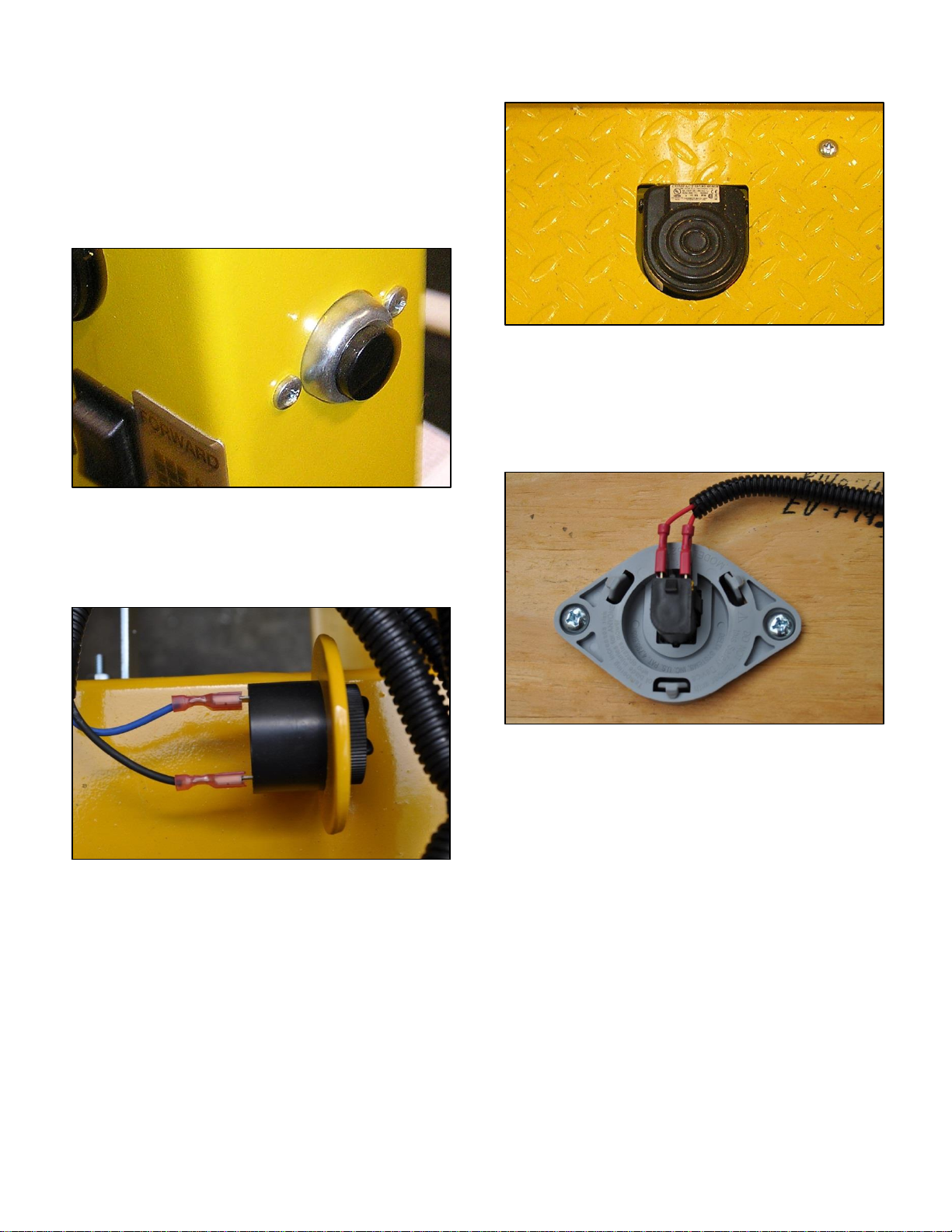
Horn and Horn button: The horn button is located at the
top of the right side of the instrument panel. It is operated by
the right hand. The horn (Figure 13) will not sound when the
key or on/off switch is in the off position.
FIGURE 13
Back-Up Alarm (Optional): Optionally, a back-up may be
installed on the vehicle.. The back-up alarm (Figure 14) only
sounds when the directional switch is placed in the reverse
position. .
FIGURE 15
Seat Presence Sensor Switch: The presence sensor
switch is located under the seat ( Figure 16) and is designed
to prevent operation of the vehicle unless a person is sitting
down on the seat. If the driver stands up or falls off the seat
while the vehicle is in motion, the presence sensor switch
will disable the vehicle, allowing it to come to a stop.
FIGURE 16
FIGURE 14
Foot Presence Switch (Optional): The foot presence
switch, if present (Figure 15), is located on the left side of the
floor board. This is an added safety feature which may be
used alone or in combination with the seat presence sensor
switch, to prevent the vehicle from operating unless this foot
switch is first depressed. The operator must use their left
foot to depress the foot presence switch before the vehicle
will move and should the operator’s foot leave the foot
presence switch during while the vehicle is moving, the
motor will disengage and the vehicle will slow to a stop.
Owner’s Manual and Service Guide – BCG Series 16
Page 17
WARNING
WARNING
OPERATING INSTRUCTIONS
DRIVING
Follow these steps to operate your Pack Mule vehicle:
1) Disconnect the battery charger.
Unplug the battery from the external battery cord. Plug
the battery back into the vehicle and lower the seat back
into position.
2) Check for correct tire inflation (pneumatic tires
only).
3) Inspect for fluid leaks.
4) Ensure surrounding area is clear of all obstructions
and everything properly stored and secured.
5) Make sure you are properly seated in the operator’s
seat.
6) Turn the key or on/off switch to the ON position.
Be sure that the directional switch is in the neutral
position and the accelerator pedal is not depressed.
Insert the key into the ignition switch (if a key switch)
located on the instrument panel. Turn the key
completely to the right to the ON position, or push the
rocker or toggle switch to the ON position. The indicator
light on the BDI should come on. If not, do not attempt
to operate the vehicle.
7) Move the directional switch to the desired setting.
Push the rocker or toggle directional switch to either the
forward or reverse position.
8) Press the speed control pedal.
Depress the speed control pedal with your foot in a
controlled manner. The speed of the vehicle will be
proportional to the amount of pressure applied to the
pedal. The controller converts the signal form the
accelerator, regulating the speed, acting as an
automatic transmission.
9) Stop
Remove your foot from the speed control pedal and
depress the separate brake pedal.
TOWING
Attach a suitable hitch to match the trailer being towed.
Wesley International offers a variety of hitches to choose
from so you can find one suitable for your application. Make
sure the hitch is properly installed and secured. Attach the
trailer to the hitch and the trailer safety chains to the
provided safety chain holes. Wesley offers a variety of
towing capacities. Do not exceed the specified towing
capacity of the vehicle. The maximum tow capacity includes
the combined weight of the trailers, the cargo on the trailers,
and the weight of the driver and cargo on the vehicle. Do
not exceed 5 mph / 8 kph when towing.
COASTING
To prevent injury or death
resulting from coasting at
above recommended
speeds, limit speed with
service brake.
On steep ramps or hills, it is possible for the vehicle to coast
at faster than normal speeds that may be encountered on a
flat surface. To prevent loss of vehicle control, speeds
should be limited to no more than the maximum speed on
level ground. Limit speed by removing your foot from the
speed control pedal and applying pressure on the separate
brake pedal.
Loading/Unloading
Make sure the vehicle has
come to a full stop before
embarking/disembarking or
before loading/unloading any
cargo. Turn off the vehicle
when loading/unloading cargo.
Do not exceed the load
capacity of the vehicle. The
maximum load capacity
includes the combined weight
of the driver and cargo. Make
sure the cargo is balanced and
securely loaded. Do not load
cargo that can easily fall off the
vehicle, especially through
turns. Be very careful when
handling cargo that is longer
or wider than the vehicle. Do
not stack cargo so that the
driver’s view is obstructed.
This vehicle is not designed to
carry passengers.
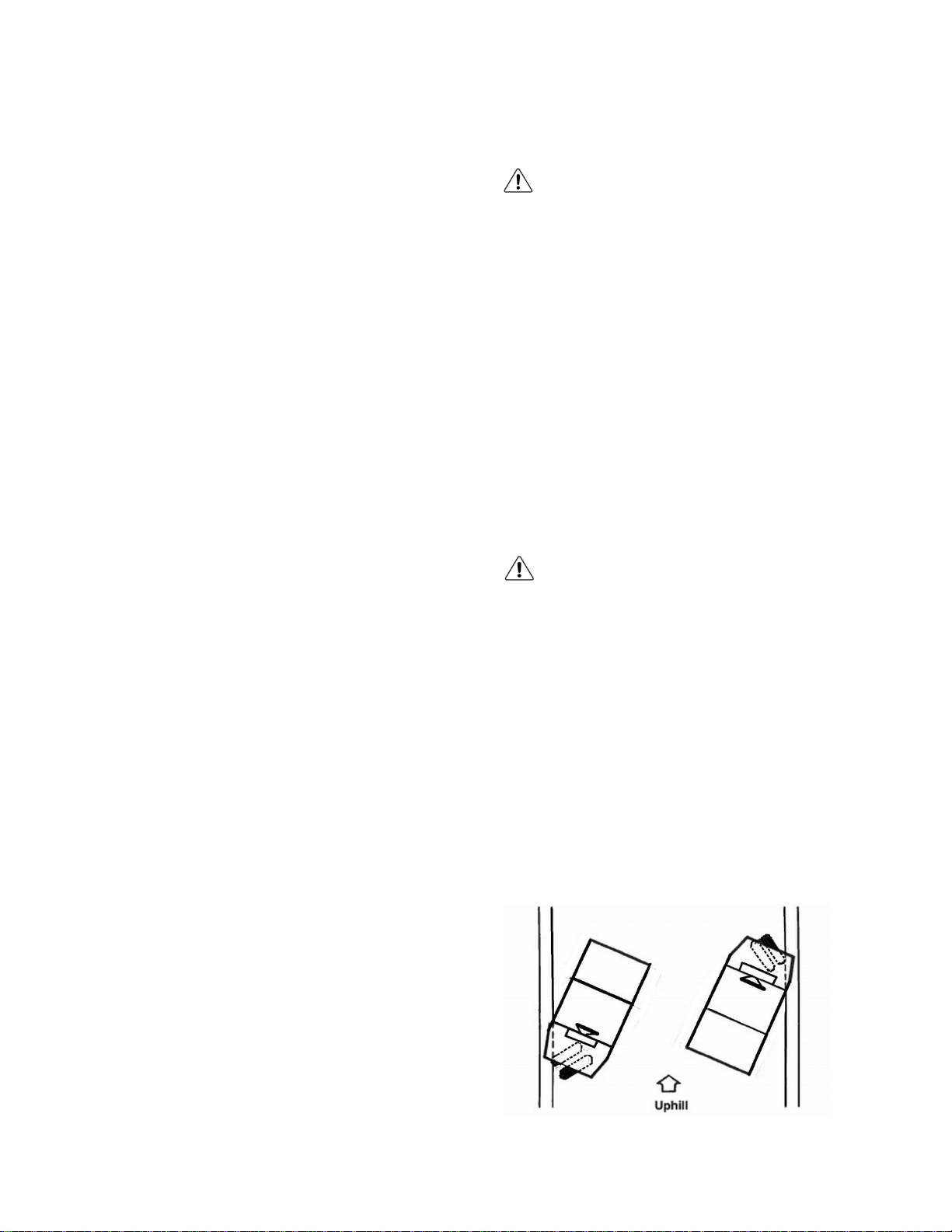
PARKING
Place the directional switch in the park/neutral
position. Turn the key switch to the off position. Latch
the parking brake on the brake pedal. If parking on an
incline, aim the front wheel toward the curb as shown
in the diagram below
17 Owner’s Manual and Service Guide – BCG Series
Page 18

VISUAL
OK
FIX
Obvious damage
Cracked frame welds
Model tag readable
Tires (proper inflation and
cut free)
Leaks
Charging cord unplugged
Wire insulation undamaged
Battery connections
Battery water level
Steering
Brakes
Horn (switch must be turned
on)
Battery discharge indicator
COMMENTS
START UP CHECKLIST FOR INDUSTRIAL TRUCKS
All industrial trucks that are used within <<Company>> are required to be inspected each day prior to use.
TRUCK NO. ___________ OPERATOR _________________ DATE _____
Owner’s Manual and Service Guide – BCG Series 18
Page 19

MAINTENANCE INSTRUCTIONS
SERVICE
BI-ANNUAL
125 Hours
ANNUAL
250 Hours
Check wheels for bent rims, missing or loose lug nuts
X
X
Check brake linkage; Check brake linings and other components for wear and
deterioration
X
X
Oil all moving parts that do not have fittings with an oiler or brush (SAE 30 oil)
X
X
Grease fork pivot fittings and gears with automotive grease using a grease gun
X
X
Check and tighten all loose nuts and bolts
X
X
Inspect steering, gear housing, and linkage
Tighten as necessary
X
X
Check oil level in transaxle
X
X
Tighten any loose battery terminals and coat terminals with petroleum jelly
X
X
Clean batteries & terminals with ¼ cup (60 mL) baking soda to 1 ½ gal (6L) water;
ensure charger is de-energized
X
X
Check electrolyte levels of all battery cells using hydrometer1
X
X
Clean, inspect, & repack front axle and steering fork bearings with lithium based
grease
X
Lubricate steering drive chain; Check for wear
X
MAINTENANCE SCHEDULE
Safe trouble-free operation of your electric vehicle depends on regular and proper preventive maintenance. The following chart is
a guide for servicing your Pack Mule electric vehicle.
₁ In freezing temperatures recharge the batteries after adding distilled water to make sure the water mixes with the electrolyte properly. Otherwise
the water may freeze and damage the batteries.
₂ The recommended pneumatic tire pressure is 60 psi. Over or under inflation can reduce tire life and adversely affect vehicle handling. It may also
lead to sudden tire failure which can result in the driver losing control of the vehicle.
₃ A hydrometer is used to determine if a battery is properly charged. It measures the specific gravity of the electrolyte (liquid) in the battery. The
electrolyte is about 1.260 in specific gravity when the battery is fully charged and about 1.100 in specific gravity when the battery is fully
discharged.
19 Owner’s Manual and Service Guide – BCG Series
Page 20
WARNING
CAUTION
MAINTENANCE INSTRUCTIONS
ROUTINE MAINTENA NCE
Before performing any
maintenance or repair work,
isolate the batteries from the
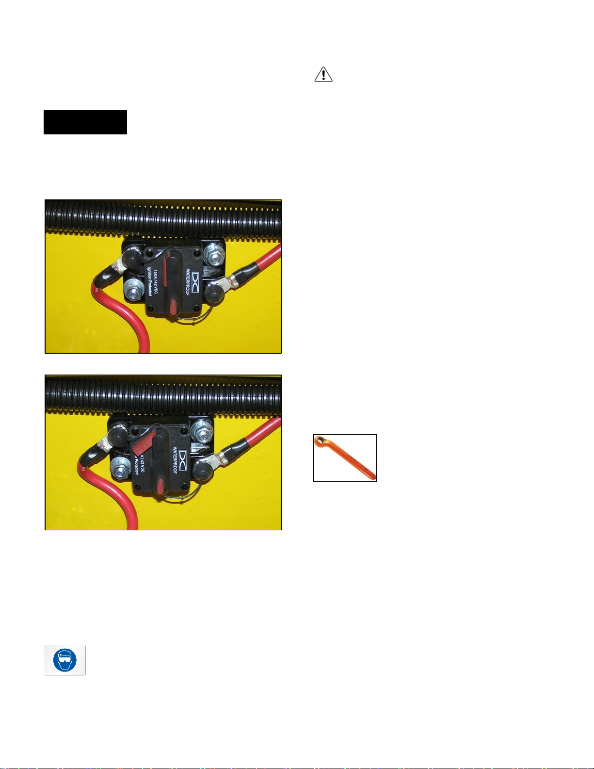
motor and electronics by opening the circuit breaker in
(Figure 17). Simply push the red push button until the
red side lever fully opens (Figure 18). To close the
circuit breaker, simply push the red side lever to its
original closed position. (Figure 17)
FIGURE 17
BAT TERY SAFETY
Always observe the following warnings when working on or
near batteries:
To prevent burns or battery explosion that could result
in severe personal injury or death, keep all smoking
materials, open flame or sparks away the batteries.
Hydrogen gas forms when charging batteries. Do NOT
charge batteries without adequate ventilation. Seat must
be raised when charging batteries. Only a 4%
concentration of hydrogen gas is explosive.
Be sure the key switch or on/off switch is in the OFF
position and all electrical accessories are off before
starting work on the vehicle. Open the vehicle’s circuit
switch (Figure 18) before starting work on the vehicle.
The electrolyte in a lead acid battery is an acid solution
which can cause severe burns to the skin and eyes.
Treat all spills to the body and eyes with extended
flushing with clear water. Then contact a physician
immediately.
Electrolyte spills will corrode the vehicle’s structural
frame and body if not properly treated immediately. In
the event of a spill, wear proper protective clothing,
gloves, and eye wear. Thoroughly clean all affected
areas with a neutralizing solution of ¼ cup (60 mL)
sodium bicarbonate (baking soda) dissolved in 1 ½
gallons (6 L) of water.
FIGURE 18
BATTERIES
The standard batteries used on Pack Mule vehicles are a 36
or 48 industrial battery pack. This manual is written around
lead acid batteries. Batteries have a maximum life.
Therefore, good maintenance is important to maximize the
available life of the vehicle’s batteries.
Always wear approved safety goggles or
face shield when handling or working
around batteries.
It is highly recommended that
insulated wrenches be used when
working on our electric vehicles.
Alternatively, wrap wrenches with vinyl
tape to prevent the possibility of a
dropped wrench onto the batteries
terminals, which can short the battery, which could
result in an explosion and severe personal injury or
death.
BATTERY CARE
1) Place battery into service and complete a full discharge
and charge cycle. Check and add approved water only
(never acid) if needed only after this first cycle is
completed.
2) Never discharge battery beyond 80% and do not
operate battery if the specific gravity is below 1.150
3) If above 115o F (46o C) allow battery to cool before
charging or operating
Owner’s Manual and Service Guide – BCG Series 20
Page 21
MAINTENANCE INSTRUCTIONS
4) During shipment or prolonged storage the electrolyte
levels may fall below the separator protector. Only after
a complete discharge and charge cycle, check and keep
electrolyte level above separator and 1/8” (3.175mm)
below vent well. Add approved water only when
required and never add acid.
5) Keep battery top clean, dry and vent caps tightly in
place.
6) Keep open flame and metal objects away from battery
top.
7) Use only approved chargers of correct voltage and
current output.
8) Keep battery compartment open and well ventilated
during charge.
9) It is recommended that water be added to batteries near
the end of the charge or after taking them to charge.
10) Be sure to replace the vent caps after watering so
electrolyte does not splash out.
ELEC TROLYTE LEVELS
Charge the batteries after each days use. Clean the
batteries and wire terminals. Check that the electrolyte level
is correct and add water as required. It is important that the
water used be pure and free of contaminants that could
reduce the life of the battery by reducing the chemical
reaction. The water must be distilled or purified by an
efficient filtration system.
Electrolyte level should be ½” (13 mm) above the plates in
each cell. This level will leave about ¼” – 3/8” (6 – 10 mm)
of space between the electrolyte and the vent tube. The
level of the electrolyte is important. Too low and the plates
will be exposed to air, ruining them beyond repair. Too high
and the electrolyte will be forced out of the battery due to
gassing and the increased volume of the electrolyte resulting
from the charging cycle.
To use the watering system, simply fill the gravity feed
container with a clean water source. Connect the blue
connector at the end of the container flow tubing to the blue
connector at the end of the battery watering system attached
to the batteries. Elevate the gravity feed container at least 3
feet (1 m) to properly fill the batteries.
CLEANING BATT ERIES
It is important to first neutralize any acid deposits with a
solution of sodium bicarbonate (baking soda) and water.
Spray the top and sides of the batteries with this solution.
Use ¼ cup (60 mL) of sodium bicarbonate mixed with 1 ½
gallons (6 L) of water. Let the solution sit for at least three
minutes. Rinse entire area with low pressure clear water.
BATTERY RE PLACEMENT
Remove battery hold downs and cables. Lift out batteries
with a safety rated lifting device.
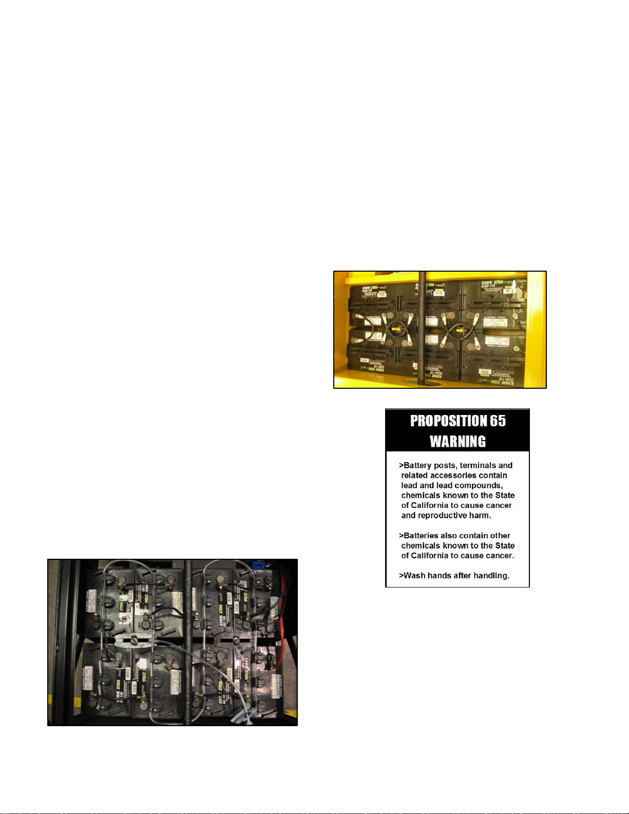
48 VOLT SY STEM WIRIN G
BATTERY WATERING SYSTEM
Wesley International offers a battery watering system,
(Figure 19), as an option on all its vehicles. This system is a
fast, accurate, and safe means of maintaining precise
electrolyte levels in the batteries.
FIGURE 19
21 Owner’s Manual and Service Guide – BCG Series
Page 22
WARNING
MAINTENANCE INSTRUCTIONS
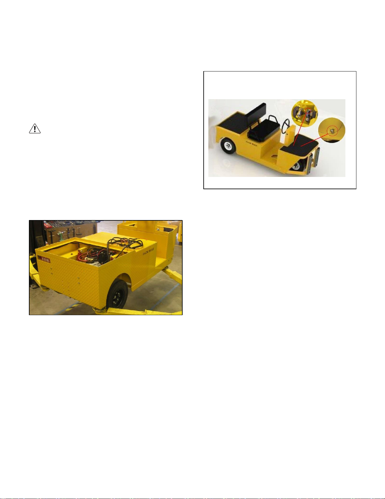
Illustration of vehicle’s lubrication points
FIGURE 21
LIFTING THE VEHI CLE
To prevent possible injury
or death resulting from a
vehicle falling from a jack, be
sure the vehicle is on a firm
and level surface. Never go
beneath a vehicle while it is
supported by a crane or jack.
Use jack stands and test the
stability of the vehicle. Always
place chocks in front and
behind the wheels not being
raised. Use extreme care when
lifting due to the 3-point wheel
design which is extremely
unstable when lifting,
especially lifting the rear.
The vehicle should only be lifted high enough to remove the
front axle or rear wheels. Position jacks and jack stands only
on the areas indicated (Figure 20).
LUBRICATION
Proper lubrication will ensure maximum years of trouble free
service from your Pack Mule.
Front Fork and Steering: Lubricate wheel bearings and fork
pivot and steering bearing (Figure 22), per the
recommended maintenance schedule.
FIGURE 20
Lifting the front: To remove a front wheel or axle: First
chock the front and rear of the rear tires. Loosen the front
wheel hardware. Position the jack in the location indicated
and carefully raise the front of the vehicle, taking care that
the rear wheels do not move. Position jack stands in the
locations indicated and slowly lower the vehicle to rest on
the jack stands and test the stability of the vehicle.
Lifting the rear: To remove a rear wheel or axle: First raise
the front of the vehicle as previously described and support
on jack stands. Then position the jack in the position
indicated at the rear of the vehicle. Carefully raise the rear
of the vehicle with the jack and place two jack stands in the
positions indicated. Slowly lower the vehicle to rest on the
jack stands and test the stability of the vehicle .Lower the
vehicle by reversing the lifting sequence.
Owner’s Manual and Service Guide – BCG Series 22
Page 23
MAINTENANCE INSTRUCTIONS
Fill Plug
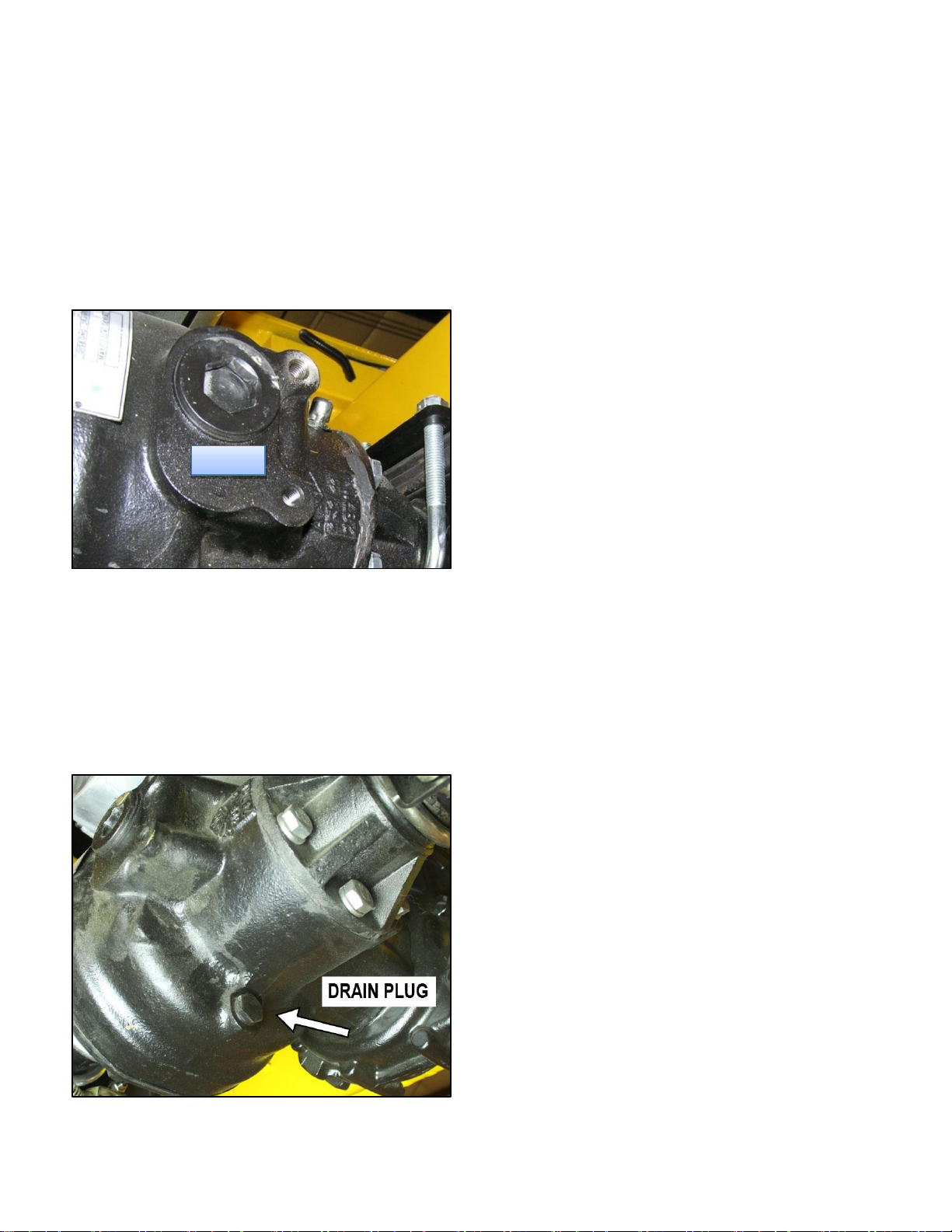
Rear Axle: Check fluid level in the rear axle per the
recommended maintenance schedule. The rear axle is
provided with a fluid level check/fill plug (Figure 23) located
at the bottom of the differential. With the vehicle on level
ground, clean the area around the check/fill plug and remove
plug. The correct fluid level is just below the bottom of the
threaded hole. If fluid levels are low, add as required until it
starts to seep from the hole. Replace the check/fill plug.
FIGURE 22
To replace the fluid, lift the vehicle per the lifting procedures.
Remove the rear axle cover and drain out the fluid into a
container. Clean cover mating surfaces as required with
proper scraping tool. Ensure cover lip is not bent. Apply thin
bead of RTV sealant and torque cover bolts 16-24 lb-ft.
Add 10-14 oz. 80W-90 Hypoid gear oil through the check/fill
plug hole or until fluid just starts to seep from the hole. When
draining the oil, remove drain plug (figure 23) and empty into
a pan.
REGENERATIVE BRAKING
Normal braking uses the regenerative braking which is
activated by the release of the Accelerator Pedal. (The
amount of regenerative braking or deceleration can be
adjusted within the Curtis Motor Controller. See instructions
on Page 29).
STANDARD MECHANICAL DRUM BRAKES
The vehicle comes equipped with twin mechanical drum
brakes. These rear brakes work with the regenerative
braking to increase stopping capability and are also used as
the parking brake. Service mechanical brakes per the
recommended maintenance schedule. Adjustments are
made by turning the connecting rod with a wrench.
TIRES A ND WHE ELS
The BCG series has an 8,000 lb tow capacity. The transaxle
has a five bolt pattern for the wheels.
The following tire options are offered with the BCG series
vehicle:
1) Solid tires (black)
2) Solid non-marking tires (off-white)
3) Soft solid tires
Solid tires are solid rubber compound mounted on a two
piece rim. They eliminate the possibility of flat spots and the
maintenance associated with pneumatic tires but because
they are solid, they do not provide as smooth a ride as
pneumatic tires. Solid non-marking tires operate in the same
manner but are made of a rubber compound that prevents
black marks on floors.
Soft Solid tires are a rubber wheel which has molded
recesses in the tire that create a smoother ride similar to a
pneumatic tire.
FIGURE 22
23 Owner’s Manual and Service Guide – BCG Series
Page 24

MAINTENANCE INSTRUCTIONS
Replacing Front Tires/Wheels: To remove and repair the
front tires and/or wheels, complete the following steps:
1) Remove the axle nut retaining clip.
2) Lift the front of the vehicle as explained in the
“Lifting the Vehicle” Section.
3) Loosen the axle nuts and remove the entire wheel,
hub and axle assembly from front fork.
4) Remove the lug nuts and remove the wheel from
the axle assembly.
5) Reinstall the repaired or replacement tire by
reversing the above sequence. Tighten to 70 to 80
ft. lbs. (95 to 108 Nm) torque.
Replacing Rear Tires/Wheels: To remove and repair the
rear tires and/or wheels, complete the following steps:
1) Loosen the lug nuts on the wheel.
2) Lift the rear of the vehicle as explained in the
“Lifting the Vehicle” Section.
3) Remove the lug nuts and remove the wheel from
the transaxle.
4) Reinstall the repaired or replacement tire by
reversing the above sequence. Tighten to 70 to 80
ft. lbs. (95 to 108 Nm) torque.
COMPONENTS - ELECTRICAL
Owner’s Manual and Service Guide – BCG Series 24
Page 25
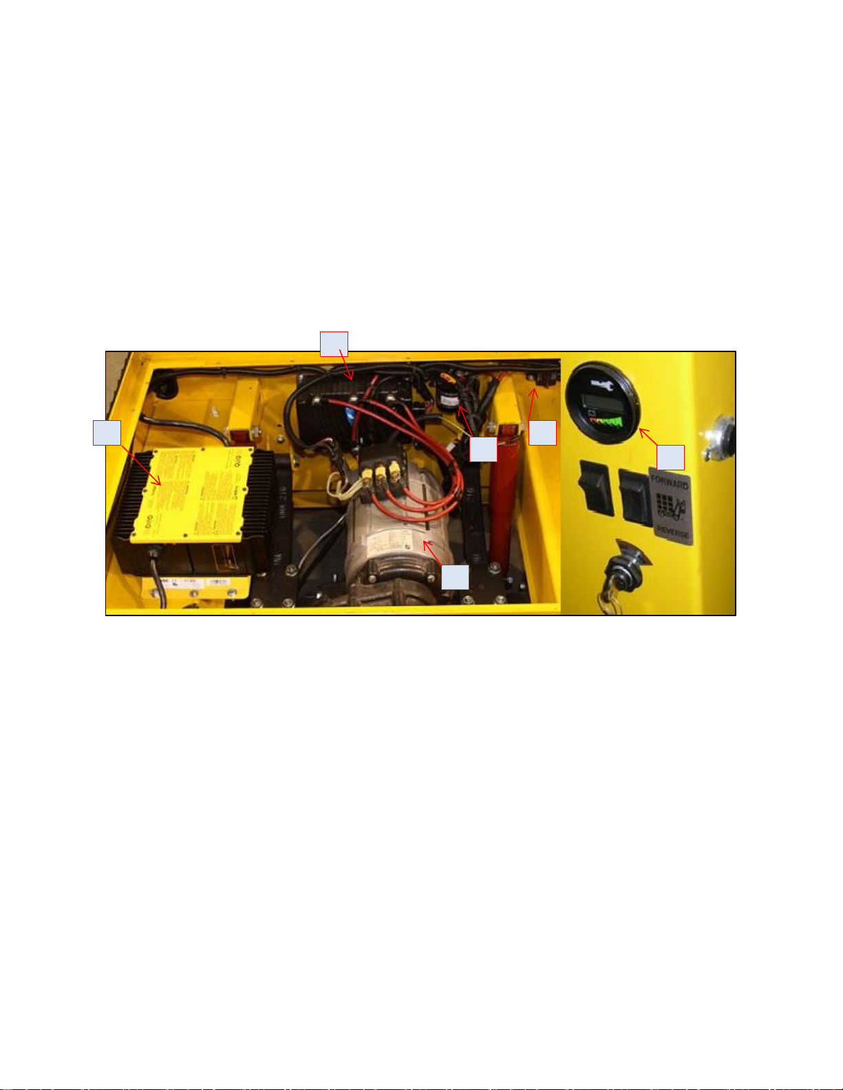
BASIC ELECTRICAL COMPO NENTS
4 3 8
5 7 1
Your Pack Mule electric vehicle is purposely designed around the “Keep it Simple” principal. Our philosophy at Wesley
International is to engineer products with only the critical components necessary to meet the demanding industrial environment,
cutting out any unnecessary “bells and whistles” which only increase ownership costs. The following core components make up
the electrical portion of the vehicle:
1) Special Order Onboard Battery Charger
2) Industrial Battey ( not shown )
3) Motor
4) Controller
5) Battery Discharge Indicator (BDI)
6) Speed Control Pedal (Shown on Page 43)
7) Solenoid
8) Circuit Breaker
This section will cover each of these core components (except batteries which is covered in the Maintenance section), including
troubleshooting.
COMPONENTS - ELECTRICAL
25 Owner’s Manual and Service Guide – BCG Series
Page 26
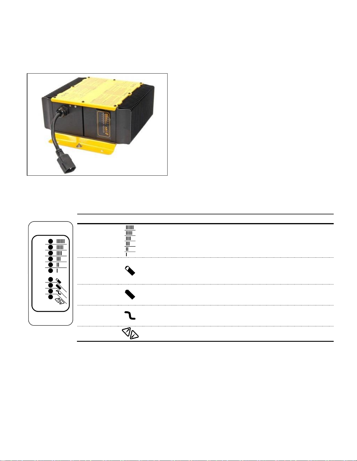
SPECIAL ORDER ONBOARD BATTERY
LED Color
Indication (following “Power-On Self Test”)
Ammeter
(Amber)
Solid:
Flashing:
Displays approximate scale of current output during bulk phase.
High internal charger temperature. Output reduced.
80% Charge
(Amber)
Solid:
Flashing:
Bulk charge phase complete, 80% charged. In Absorption phase.
With no battery connected, indicates algorithm # selected by
number of flashes.
100% Charge
(Green)
Solid:
Flashing:
Charging complete. Charger in Maintenance Mode.
Absorption phase complete. In Finish phase
AC On
(Amber)
Solid:
Flashing:
AC power good.
Low AC voltage. Check voltage and extension cord length.
Fault
(Red)
Flashing:
Charger error. Reset charger power and refer to trouble shooting
instructions.
CHAR GER
This section is included in case your unit has the optional
onboard Delta-Q Battery Charger ( Figure 25).
The onboard charger is air cooled, eliminating any moving
parts for increased reliability and life span. Because of this,
the mounting location has been designed to optimize air flow
and it is important that this air flow is not inhibited in any
way. Regularly check the cooling fins to ensure they are
free of dirt, dust, or other contaminants.
The charger is an IP66 (NEMA4) enclosure and is designed
for an operating temperature of -30oC to +50o C (-22o F to
122o F). It accepts AC input voltage range of 85 – 265 VAC
with a nominal input voltage of 120 VAC or 230 VAC rms.
The input frequency range is 45 – 65 Hz with a maximum
input current of 12A and a nominal input current of 9.5A rms
at 120 VAC or 5A rms at 230 VAC.
FIGURE 24
The charger includes an easy to read 10-LED display as follows:
Owner”s Manual and Service Guide – BCG Series
Page 27
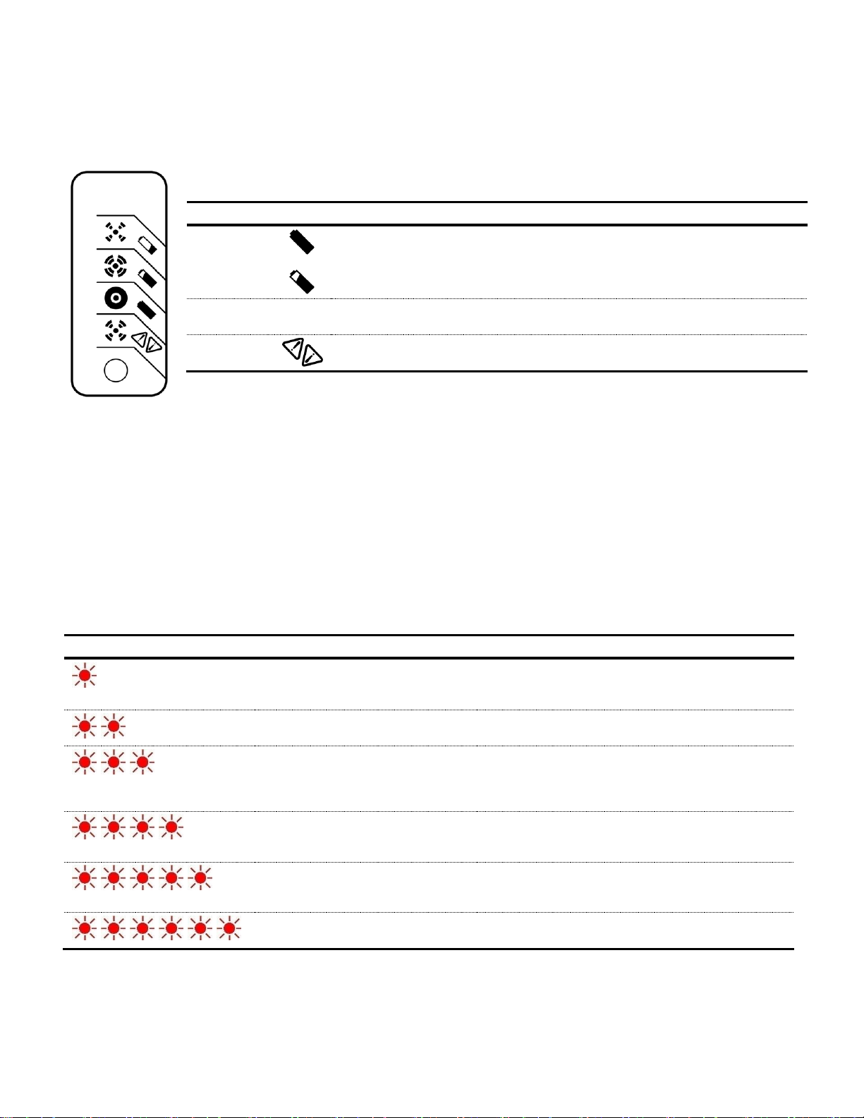
COMPONENTS - ELECTRICAL
Red Flashes
Cause
Solution
Battery High Voltage
Check battery size and condition and reset charger
(interrupt AC power for 15 seconds).
Battery High Voltage
Check battery size and condition and reset charger
(interrupt AC power for 15 seconds).
Charge Timeout caused by battery
pack not reaching required voltage.
Charger output was reduced due to
high temperatures.
Check connections.
Operate charger at a lower ambient temperature.
Check Battery: Battery could not be
trickle charged up to minimum
voltage
Check for shorted or damaged cells.
Over-Temperature: Charger shut
down due to high internal
temperature.
Ensure sufficient cooling air flow and reset charger
(interrupt AC power for 15 seconds).
Charger Internal Fault
Reset charger (interrupt AC power for 15 seconds). If
fault persists, likely needs to be replaced.
LED Color
Indication (following “Power-On Self Test”)
Green
Solid:
Flashing:
Charging complete. Charger in Maintenance Mode.
Short: <80% Charge
Long: >80% Charge
Amber
Flashing:
Reduced power mode: Low AC voltage or High internal charger
temperature.
Red Flashing:
Charger error. Reset charger power and refer to trouble shooting
instructions.
The optional charger Single-LED display, if included, would be located on the front panel, near the key-switch.
1) Do not expose charger to oil, mud or direct heavy water spray when cleaning vehicle.
2) If the detachable input power supply cord set is damaged, replace with a cord that is:
a. For North America – UL or CSA listed/approved detachable cord, 3 conductor, 16AWG minimum, and rated SJT;
terminating in a grounding type IEC 60320 C14 plug rated 250V, 13A minimum; or
b. For all other countries – a safety approved detachable cord, 3 conductor, 1.5mm2 minimum, rated appropriately
for industrial use. The cord set must terminate on one end with a grounding type input connector appropriate for
use in the country of destination and, on the other end, an output grounding type IEC 60320 C14 plug.
3) The enclosure of the charger has been tested successfully to EN60529, meeting IP66. The AC supply inlet is rated to
IP20, which is suitable for indoor use only. Keep all AC connections clean and dry.
If a fault occurs, count the number of red flashes between pauses and refer to the following table:
27 Owner’s Manual and Service Guide – BCG Series
Page 28
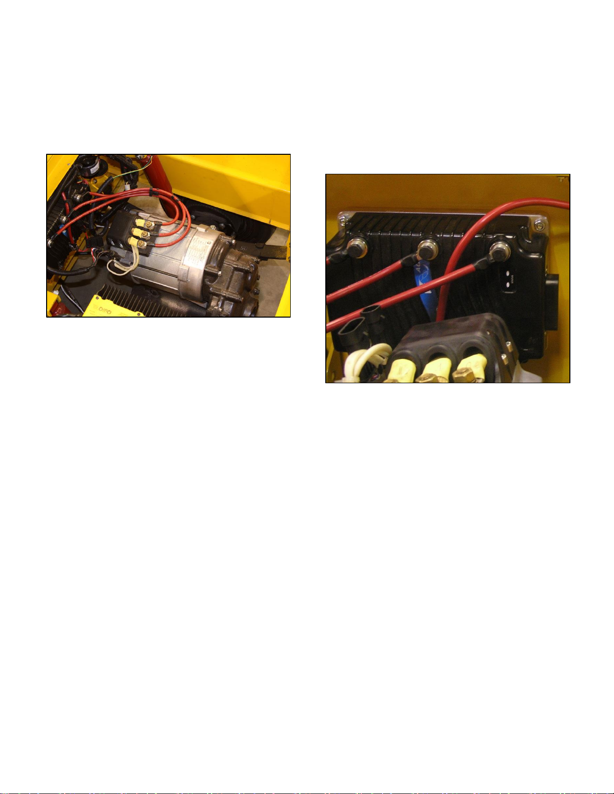
COMPONENTS - ELECTRICAL
STANDARD MOTOR
BCG Pack Mule Vehicles have industrial towing capacity
because they use the Advanced Motor and Drives’ 4.2 KW
AC Motor ( EV-E186) (Figure 26).
CONTROLLER
The BCG Series electric vehicle is equipped with the Curtis
model 1236 AC 350 amp controller (part # EV-E181) (Figure
27). This programmable controller is simple to install,
efficient, and cost effective. The Curtis controller provides
smooth precise control of motor speed and torque. The solid
state power electronics within the controller provide solid
state motor reversing and full regenerative braking without
additional relays or contactors.
FIGURE 25
FIGURE 26
The controller’s rugged IP53 housing and packaging are
built to with-stand shock and vibration. The controller is fully
programmable through the Curtis 13XX hand held
programmer and provides diagnostic and test capability.
Plus, the Curtis motor controller offers superior operator
control of the vehicle’s motor drive speed.
Owner’s Manual and Service Guide – BCG Series 28
Page 29

COMPONENTS - ELECTRICAL
Controller Features Include:
Interlock braking with load sensor to meet required
braking distance without unnecessary harsh braking
when carrying light loads
Maintenance monitor responds to preset vehicle
operating hours and drive hours as programmed by the
OEM
Two hour meters—total KSI-on hours and traction
hours—and the associated maintenance timers are built
into the controller
BDI calculations performed within controller
Estimates motor temperature based on field resistance
and cuts back maximum speed if the motor is overheated
Diagnostic checks for field open and field shorted faults
Active pre-charge of controller capacitor bank extends life
of main contactor
Compatibility with Curtis 1307/1311 hand held
programmers for quick and easy testing, diagnostics, and
parameter adjustment
Complete diagnostics through the handheld programmer,
built-in Status LED, and 840 Spyglass display
Two fault outputs provide diagnostics to remotely
mounted displays
Regenerative braking allows shorter stopping distances,
increases battery charge, and reduces motor heating
Automatic braking when throttle is reduced provides a
compression braking feel and enhances safety
Brake/Drive Interlock meets ISO stopping distance rules
Ramp restraint feature provides automatic electronic
braking that restricts vehicle movement while in neutral
Meets EEC fault detect requirements
Linear cutback of motor drive current during over-
temperature or under-voltage
Linear cutback of regenerative braking current during
overvoltage
High pedal disable (HPD) and static return to off (SRO)
interlocks prevent vehicle runaway at startup
Internal and external watchdog circuits ensure proper
software operation
Fully protected inputs and short-circuit protected output
drivers
This manual covers the most commonly required
information as it pertains to the Pack Mule vehicles. For
more detailed instructions, contact Wesley International
for a copy of the complete manual for the Curtis motor
controller, or download a copy from www.packmule.com.
Your Pack Mule vehicle should be equipped with the
following Curtis motor controller model:
AC Motor: Curtis 1236
programmer, available from Wesley. Generally, there are
five parameters which owners may want to modify to suit
their specific safety or user preferences as follows:
a) Acceleration Rate
b) Braking Rate
c) Deceleration Rate
d) Maximum Forward Speed
e) Maximum Reverse Speed
Acceleration Rate: The acceleration rate defines the time it
takes the controller to accelerate from 0% drive output to
100% drive output. A larger value represents a longer
acceleration time and a gentler start. Fast starts can be
achieved by adjusting the accel rate to a smaller value. The
acceleration rate is adjustable from 0.1 to 3.0 seconds. The
default setting for this is 1.6.
Braking Rate: The braking rate defines the time it takes the
controller to increase from 0% braking output to 100%
braking output (as defined by the corresponding modespecific brake current limit) when a new direction is selected.
A larger value represents a longer time and consequently
gentler braking. Faster braking is achieved by adjusting the
braking rate to a smaller value. The braking rate is
adjustable from 0.1 second to 3.0 seconds. The default
setting for this is 0.1
Deceleration Rate: The deceleration rate defines the time it
takes the controller to reduce its output to the new throttle
request when the throttle is reduced or released. A lower
value represents a faster deceleration and thus a shorter
stopping distance. The decel rate defines the vehicle’s
braking characteristic for any reduction in throttle, including
to neutral, that does not include a request for the opposite
direction. The decel rate is adjustable from 0.1 to 10.0
seconds. The default setting for this is 2.5.
Maximum Forward Speed: The maximum forward speed
parameter defines the maximum controller voltage output at
full throttle, in the forward direction. The maximum forward
speed parameter is adjustable from the programmed creep
speed up to 100%. The default setting for this is 70, which
equates to about 7 mph (12.9 kph).
Maximum Reverse Speed: The maximum reverse speed
parameter defines the maximum controller voltage output at
full throttle, in the reverse direction. The maximum reverse
speed parameter is adjustable from 0% to 100%. The default
setting for this is 35 or about 1/2 the forward speed.
Controller Maintenance: There are no user serviceable
parts in the Curtis controller. No attempt should be made to
open, repair, or otherwise modify the controller. Doing so
may damage the controller and will void the warranty. It is
recommended that the controller be kept clean and dry and
that its fault history file be checked and cleared periodically.
Programmable Parameters: All Pack Mule vehicles leave
the factory with standard default parameters programmed in
the controller, unless specific parameter settings are
requested at the time of order. These parameters can be
reprogrammed in the field using a Curtis handheld
29 Owner’s Manual and Service Guide – BCG Series
Periodically cleaning the controller exterior will help protect it
against corrosion and possible electrical control problems
created by dirt, grime, and chemicals that are part of the
operating environment and that normally exist in battery
powered systems.
Page 30

Use the following cleaning procedure for routine
maintenance:
1) Remove power by disconnecting the battery.
2) Discharge the capacitors in the controller by
connecting a load (such as a contactor coil or a horn)
across the controller’s B+ and B-terminals.
3) Remove any dirt or corrosion from the connector
areas. The controller should be wiped clean with a
moist rag. Dry it before reconnecting the battery. The
controller should not be subjected to pressured water
flow from either a standard hose or a power washer.
4) Inspect cable connections for damage, corrosion, and
security. Replace or repair as required. Tighten to: 90
in/lbs.
Owner’s Manual and Service Guide – BCG Series 30
Page 31
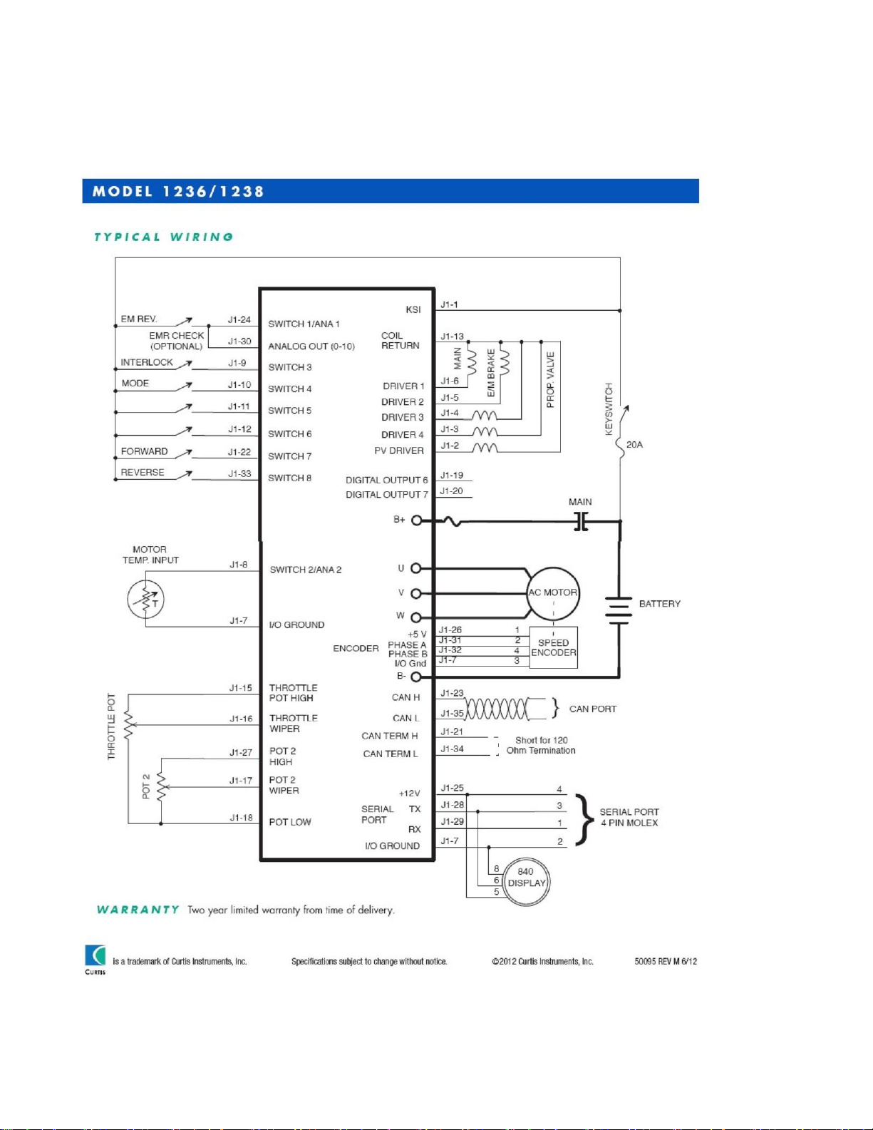
COMPONENTS - ELECTRICAL
Controller Wiring: Typical 1236 AC Motor Controller wiring configuration of BGC series vehicles. The interlock switch is a seat
switch or foot switch and there is no emergency reverse.
31 Owner’s Manual and Service Guide – BCG Series
Page 32
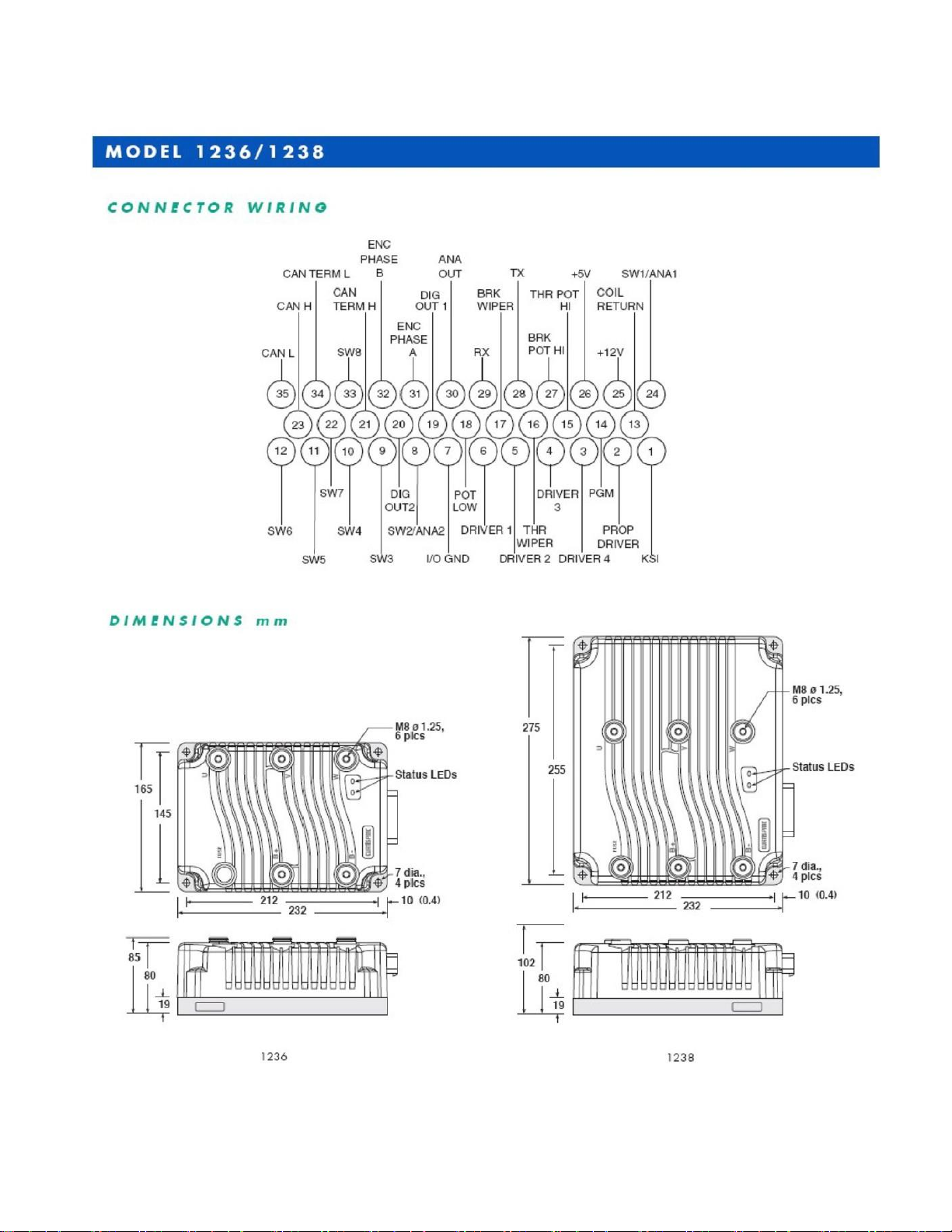
Owner’s Manual and Service Guide – BCG Series 32
Page 33
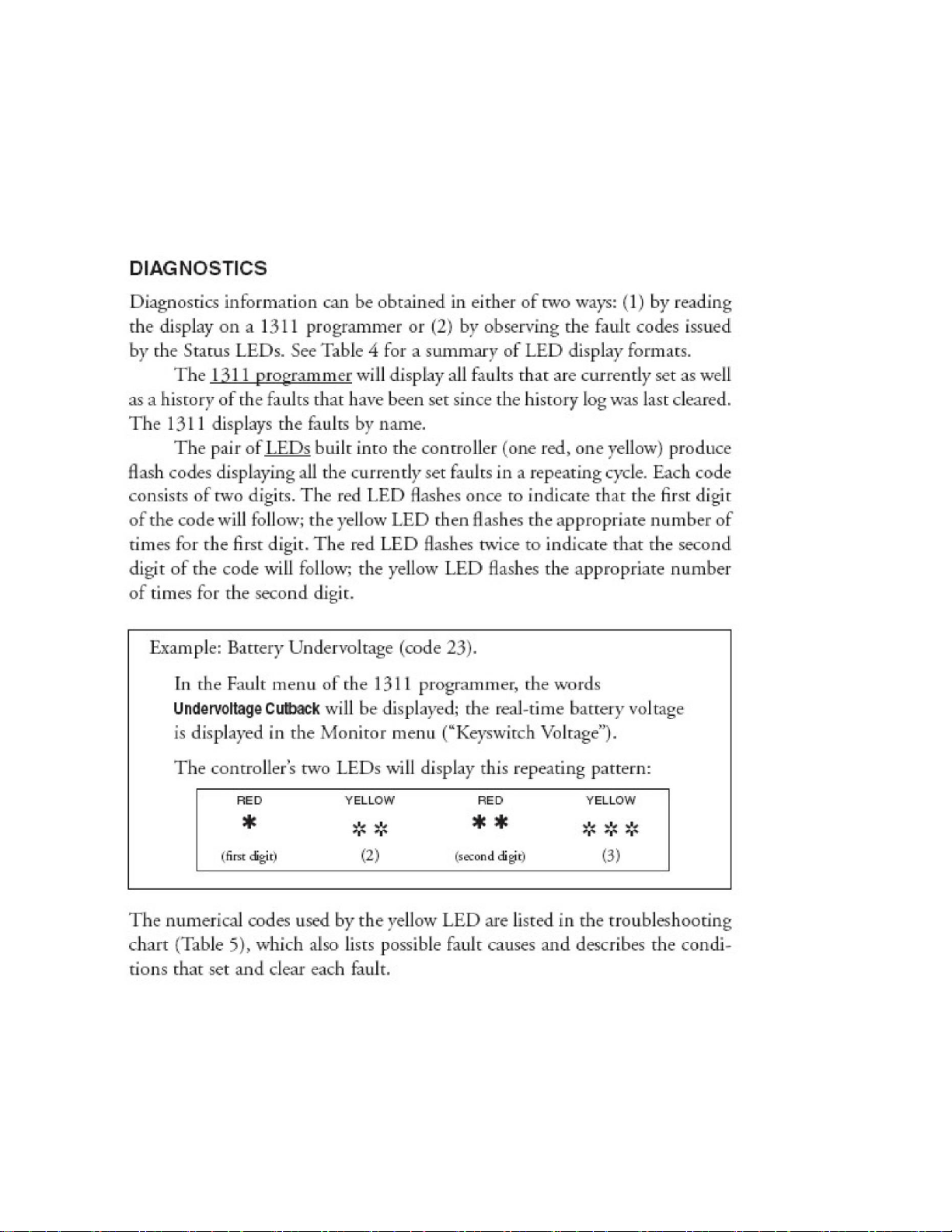
COMPONENTS - ELECTRICAL
Fault Codes and Troubleshooting Chart:
33 Owner’s Manual and Service Guide – BCG Series
Page 34
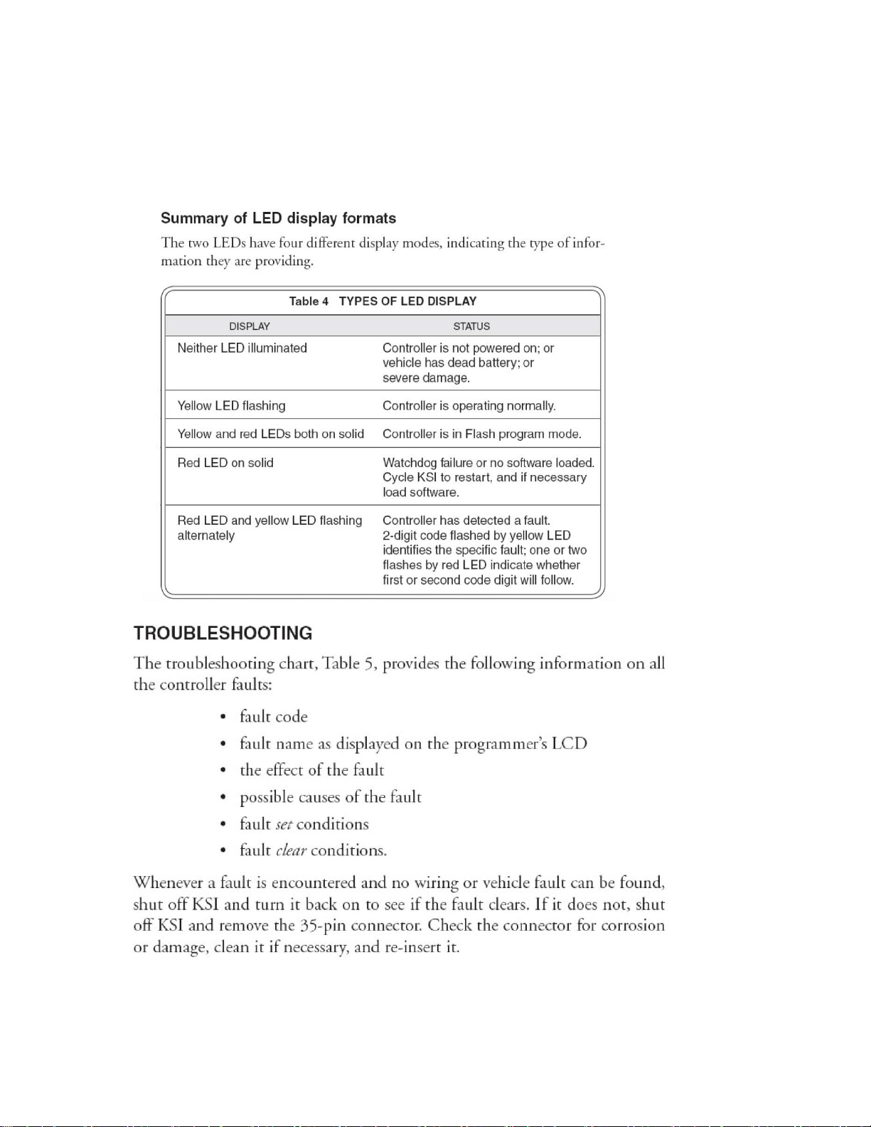
COMPONENTS - ELECTRICAL
Fault Codes and Troubleshooting Chart:
Owner’s Manual and Service Guide – BCG Series 34
Page 35
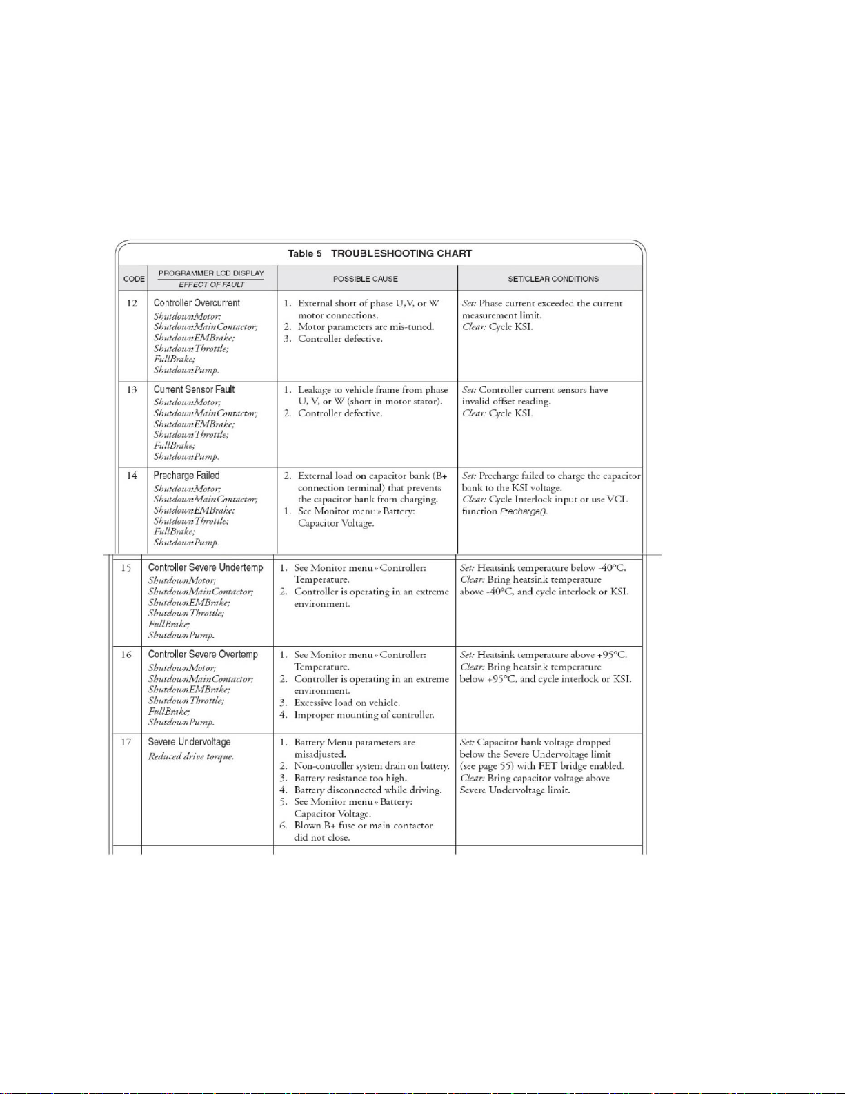
COMPONENTS - ELECTRICAL
Fault Codes and Troubleshooting Chart:
35 Owner’s Manual and Service Guide – BCG Series
Page 36
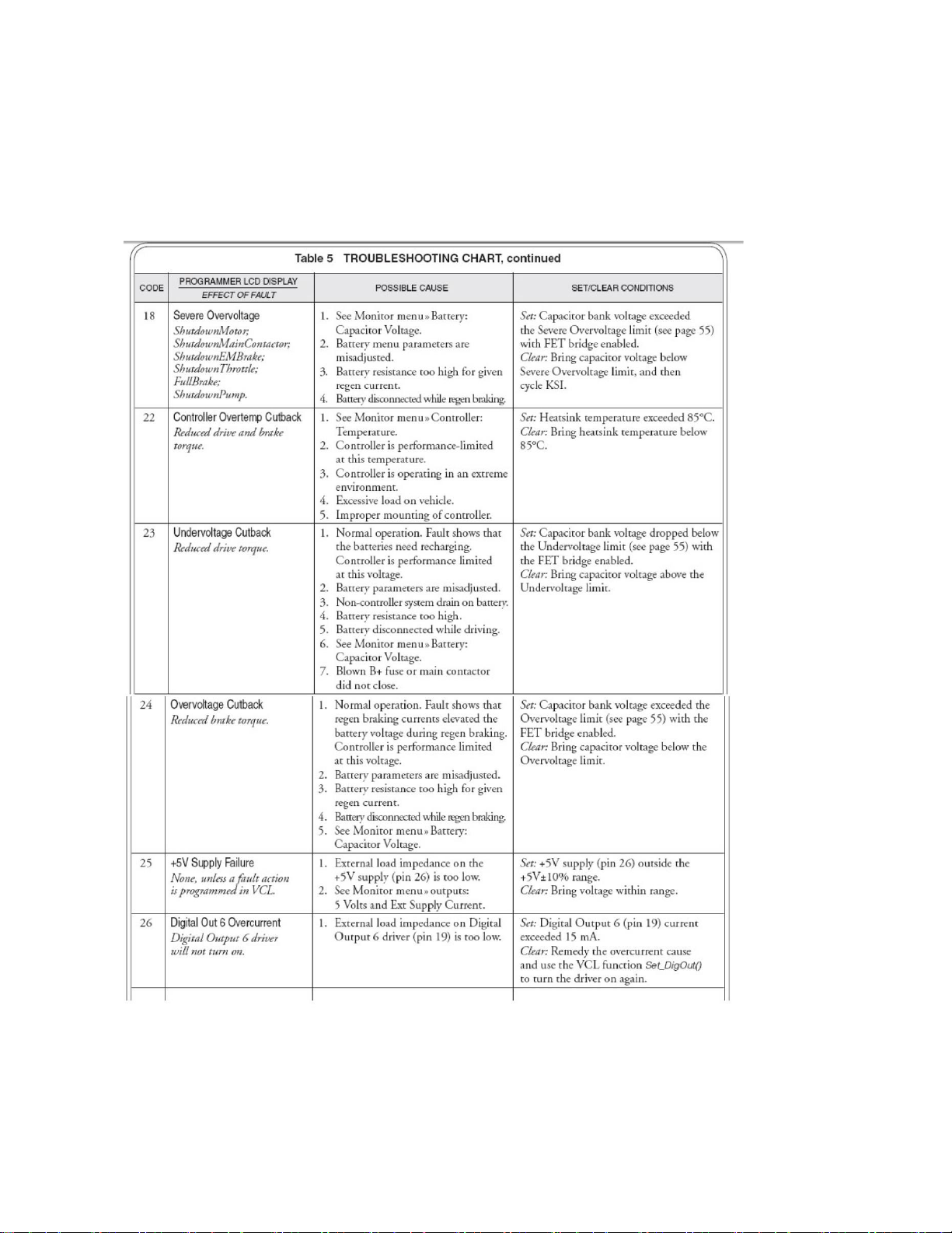
COMPONENTS - ELECTRICAL
Fault Codes and Troubleshooting Chart:
Owner’s Manual and Service Guide – BCG Series 36
Page 37
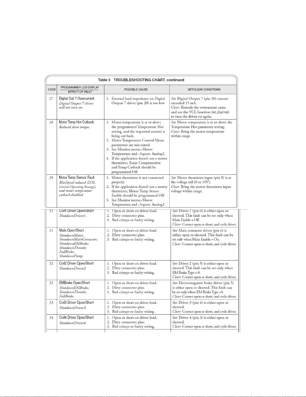
COMPONENTS - ELECTRICAL
Fault Codes and Troubleshooting Chart:
37 Owner’s Manual and Service Guide – BCG Series
Page 38
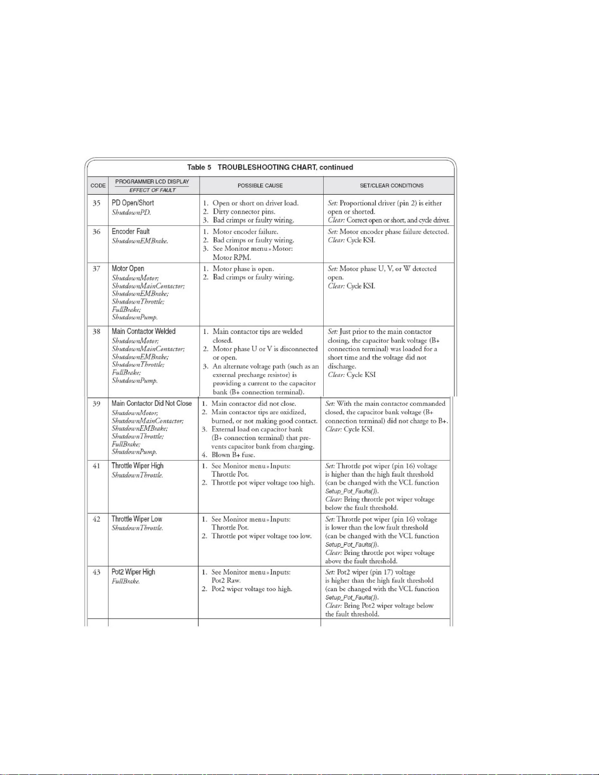
COMPONENTS - ELECTRICAL
Fault Codes and Troubleshooting Chart:
Owner’s Manual and Service Guide – BCG Series 38
Page 39
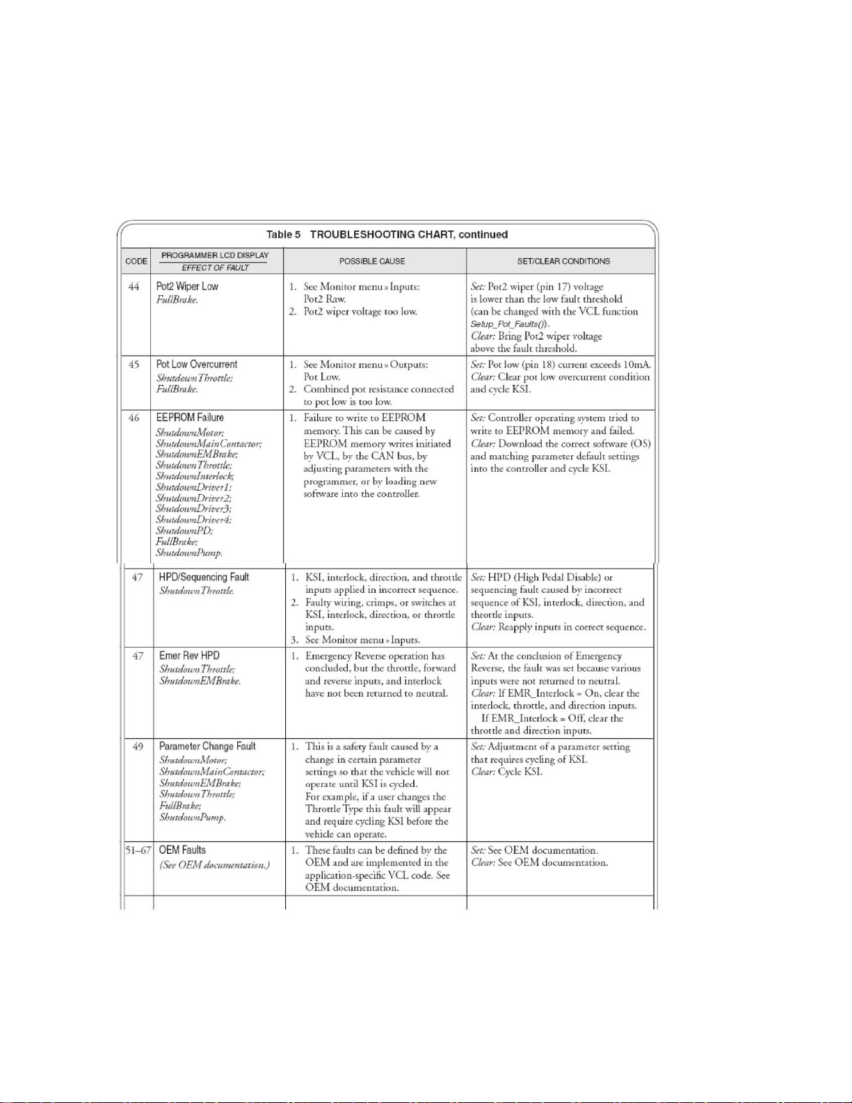
COMPONENTS - ELECTRICAL
Fault Codes and Troubleshooting Chart:
39 Owner’s Manual and Service Guide – BCG Series
Page 40
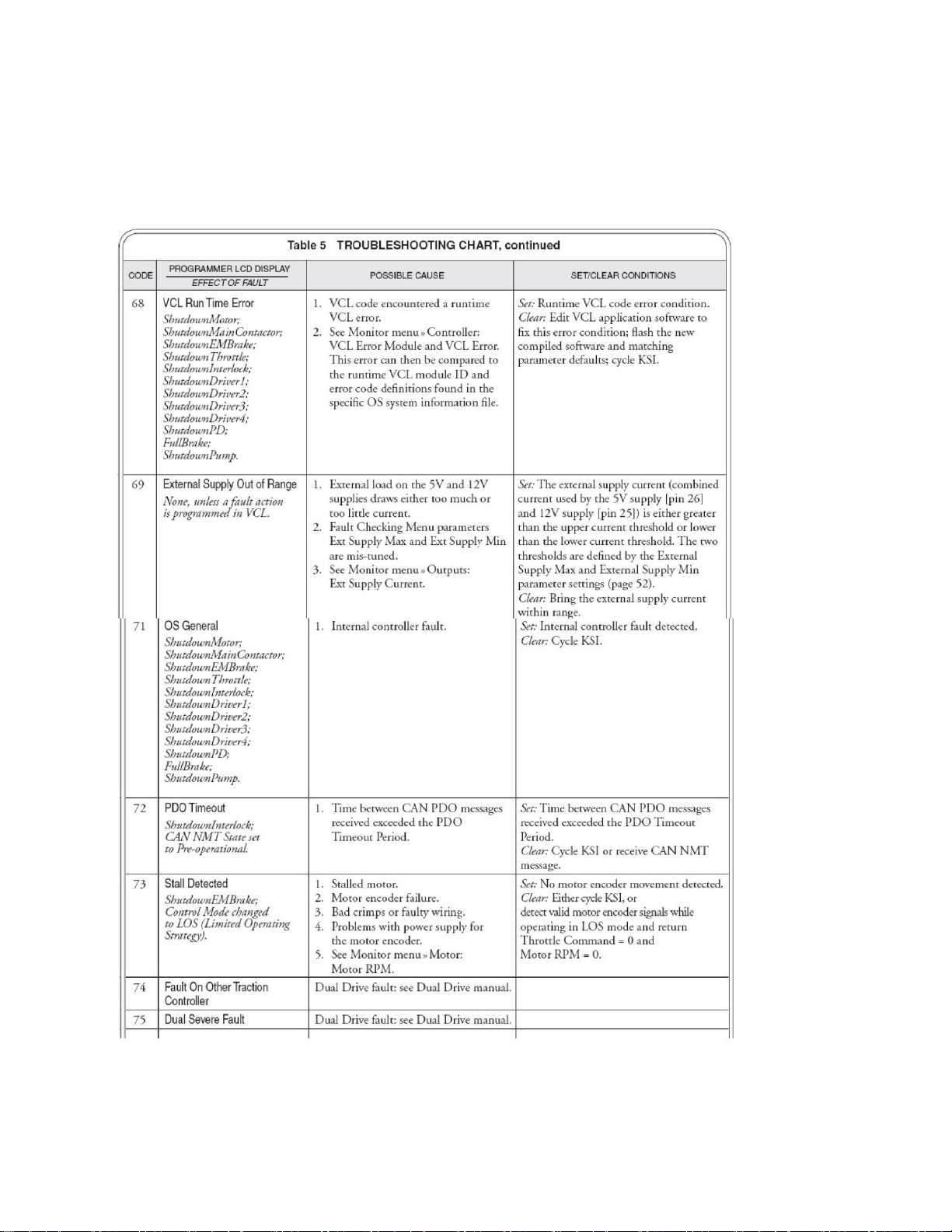
COMPONENTS - ELECTRICAL
Fault Codes and Troubleshooting Chart:
Owner’s Manual and Service Guide – BCG Series 40
Page 41
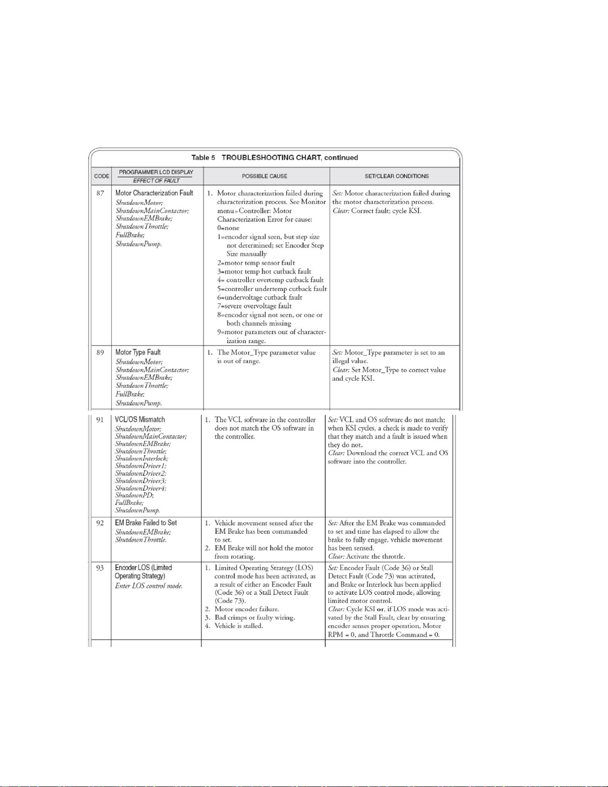
COMPONENTS - ELECTRICAL
Fault Codes and Troubleshooting Chart:
41 Owner’s Manual and Service Guide – BCG Series
Page 42
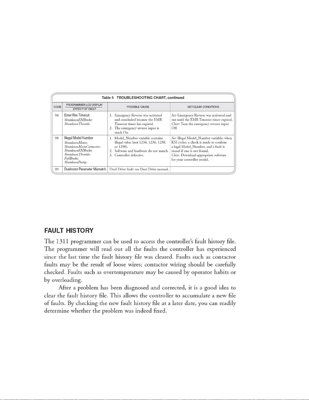
COMPONENTS - ELECTRICAL
Fault Codes and Troubleshooting Chart:
Owner’s Manual and Service Guide – BCG Series 42
Page 43
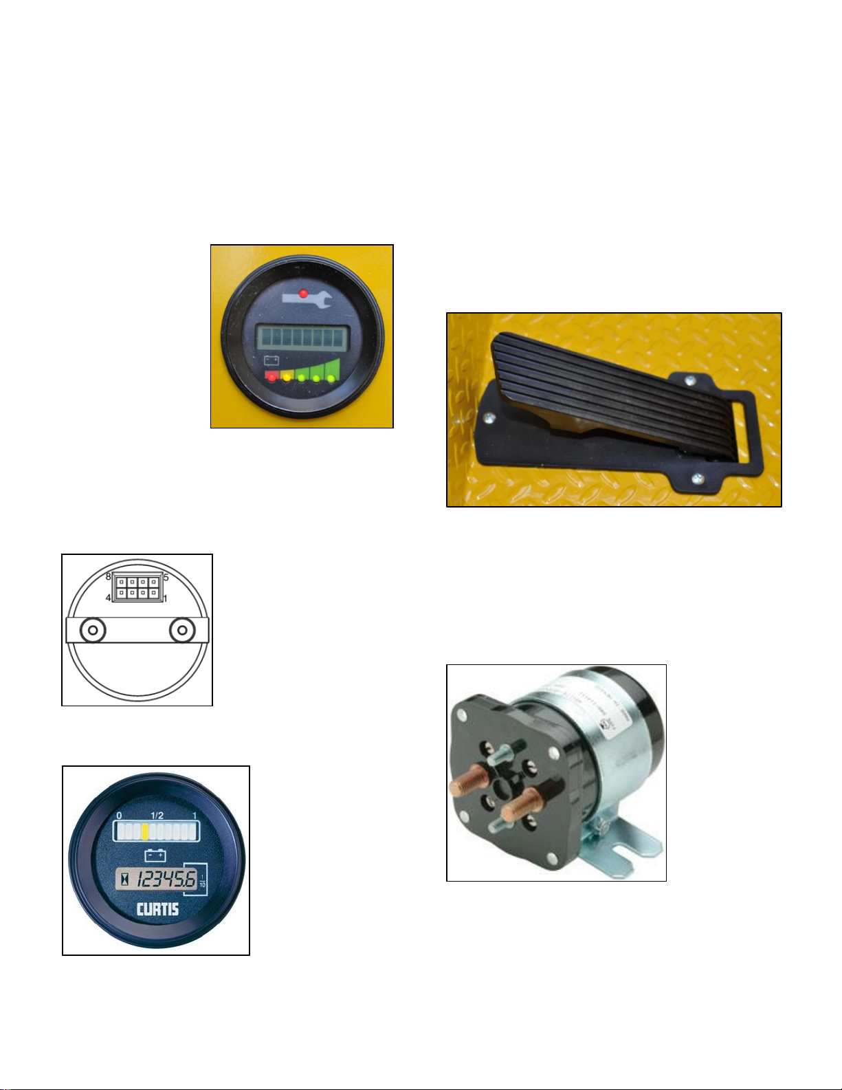
COMPONENTS - ELECTRICAL
FIGURE 27
FIGURE 28
BATTERY DISCHARGE INDICATOR (BDI)
The Curtis BDI (Figure 28 shows the 24/36V version)
displays various system parameters, such as battery stateof-charge, operating hours or maintenance status from the
Curtis motor controller.
Features include:
Attractive, easy-to-
read, 8 character dot
matrix Liquid
Crystal Display.
• 6 LEDs -five green
to indicate battery
state-of-charge and
one red to indicate
that a fault has
occurred.
• Displays hours of
use, battery state-ofcharge and
messages from the
Curtis motor
controller.
• Molded-in rear Molex style connector provides a lowcost, rugged and reliable installation.
• Front sealed (IP65) for use in harsh environments.
BDI Connector Pin-Out
Pin Number Function
1 N.C.
2 N.C.
3 B+ = 24V
4 B+ = 36V
5 Power In +
6 Receive
7 N.C.
8 Power In –
SPEED CONTROL PEDAL
The speed control pedal, (Figure 30) is located to the right of
the brake pedal. It controls the speed of the vehicle and is
operated with the right foot like the accelerator of an
automobile. Depressing the pedal starts the motor.
Releasing the pedal stops the motor. Reverse speed is half
of forward speed.
FIGURE 39
SOLE NOI D
The Pack Mule is provided with a SPNO DC Power
Contactor. This unit is sealed and is water resistant. The coil
voltage is matched to your particular vehicle operating
voltage, i.e. 36V or 48V. The AC option uses 24V coil
regardless of vehicle system voltage (Figure 31).
The BDI in 48 volt vehicles will display battery state-ofcharge and operating/ Traction hours only. Figure 29:
FIGURE 30
43 Owner’s Manual and Service Guide – BCG Series
Page 44

COMPONENTS - ELECTRICAL
Part
Part Number
Key Switch, 3-position (standard)
EV-E100
Key Replacement, set of 2
EV-E160
Directional Switch, 3 position Rocker
EV-E156
Horn
EV-E130
Horn Button
EV-E047B
BDI – 36 / 48 volt vehicles
EV-E126
Circuit Breaker
EV-E015-150A
Solenoid, 4-terminal 36V
EV-E064HD
Solenoid, 4-terminal 48V
EV-E204 HD
1 Amp Fuse
EV-E015 1A
Fuse Holder
EV-E016
Motor Controller, AC
EV-E181 -350
Motor, AC
EV-E186
Pedal Assy Flush Mount
EV-E528
Seat Presence Sensor Switch
EV-E128
PARTS LIST – ELECTRICAL
Owner’s Manual and Service Guide – BCG Series 44
Page 45

COMPONENTS - ELECTRICAL
Part
Part Number
Perma-Key Switch
EV-E194PK
On/Off Switch
EV-E017
Programmable Code Security Switch
EV-E901
Headlight/Taillight Switch, Rocker
EV-E155
Single LED Charge Status Plate
EV-E808L
Foot Presence Switch
EV-E128
Battery Watering System – 36V GC135
EV-E900-2
Battery Watering System – 36V GC145
EV-E900-1
Battery Watering System – 48V FS8D
EV-E900FX-310
Headlight – 12 -48 volt
EV-E190
Headlight/Taillight/Brake light – 24 / 36 volt
EV-E191
Headlight/Taillight/Brake light – 48 volt
EV-E191-48
Flashing Safety Beacon – Amber
EV-E183
Flashing Safety Beacon – Blue
EV-E182B
Flashing Safety Beacon – Red
EV-E182R
Back-up Alarm
EV-E159A
Proximity Alarm
EV-E149
Curtis AC/DC Program/Diagnostic Handset
EV-E180
Hitch, Spring-Loaded Clevis, 1” pin
EV-F130H
Hitch, Spring-Loaded Clevis, 5/8” pin
EV-F178H
Hitch, Pin
EV-F134P
Hitch, Pintle
EV-F092
Hitch, Eye 2-3/8”
EV-F132
Hitch, Auto Coupling
EV-F133H
Hitch, 3-Tier Assembly with Pin
EV-F134
Onboard Battery Charger, 36 volt
EV-E801-36
Onboard Battery Charger, 48 volt
EV-E801-48
Charger Cord
EV-E026
PARTS LIST – AVAILABLE OPTIONS
45 Owner’s Manual and Service Guide – BCG Series
Page 46
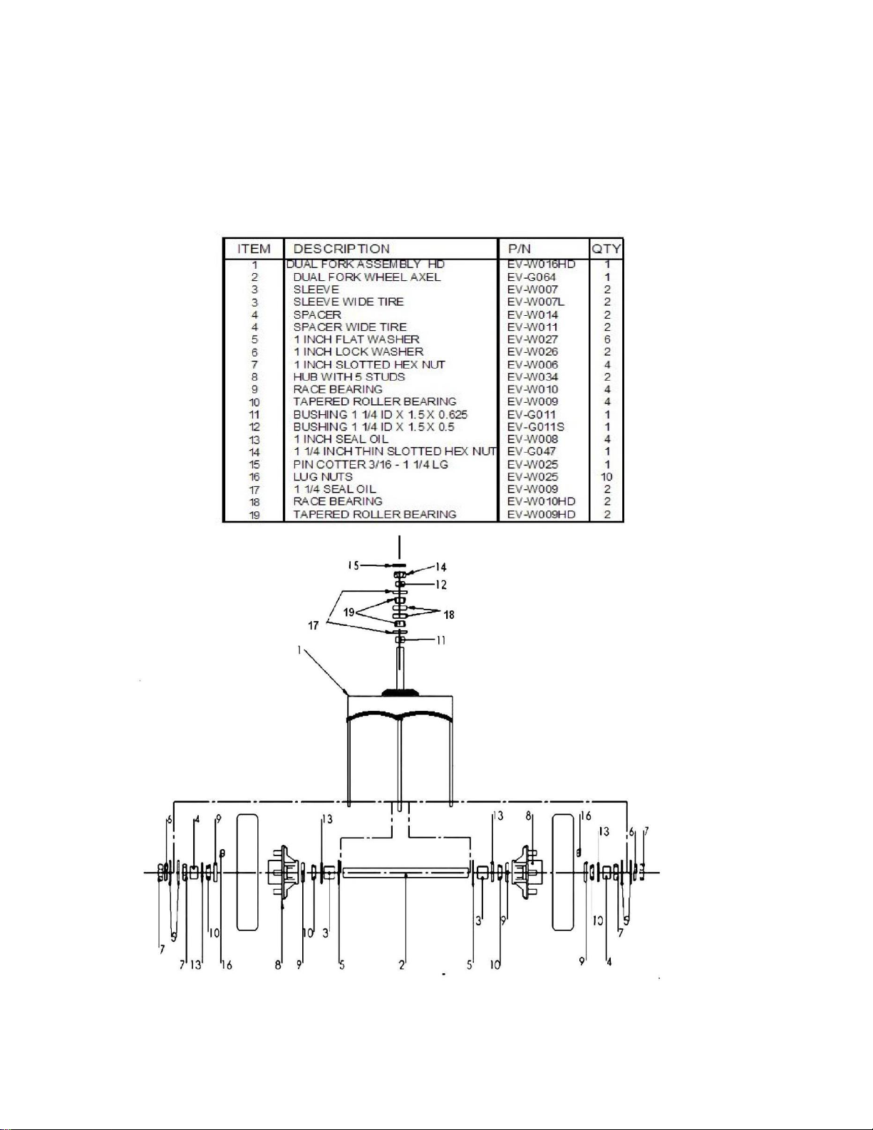
COMPONENTS - MECHANICAL
PARTS LIST – FRONT WHEEL STEER ASSEMBLY
Owner’s Manual and Service Guide – BCG Series 46
Page 47
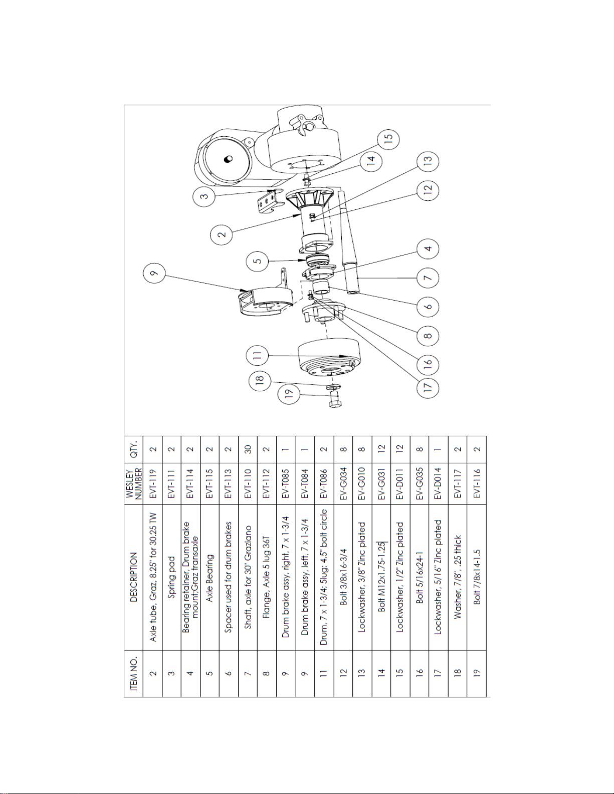
TRANSAXLE – EPLODED VIEW
47 Owner’s Manual and Service Guide – BCG Series
Page 48
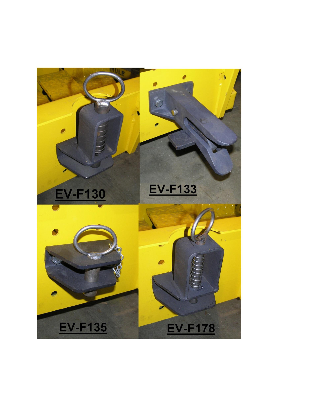
HITCHES
Owner’s Manual and Service Guide – BCG Series 48
Page 49

PROUDLY BUILT IN THE USA
Insert wiring diagram
49 Owner’s Manual and Service Guide – BCG Series
 Loading...