

Page 1
Operator’s manual
e5
Make life colorful
Page 2

Thank you for purchasing WESENA’s HTPC Chassis. We
recommend that you read this user guide thoroughly before
installation.
WESENA is the professional global supplier of HTPC cases, we
hold the professional product designing, the novel and
fashionable outside looking , humanistic inner structure of
it ,high-quality QC management and high-q ual ity produc tio n
team. At the same time we are on the line of providing the high
quality products constantly , and will never st op innovati ng and
improving the theory of development in HTPC case . The
products, Both OEM and ODM are welcomed.
More information of our products visit http://www.wesena.com
Any other question please make call 400 6088 126
WESENA is not responsible for any damages due
to external causes, including but not limited to,
improper use, problems with electrical power,
accident, neglect, alteration, repair, i mprop er
installation or improper testing.
Page 3

Index
e5 overview-----------------------------------------------------------4
Open the Top panel-------------------------------------------------5
Montherboard installation------------------------------------------5
HDD installation------------------------------------------------------6
ODD installation------------------------------------------------------8
PSU installation -----------------------------------------------------9
PCI or PCIE slot installation--------------------------------------10
Close the Top panel------------------------------------------------10
Open the cardreader door ----------------------------------------10
PCB+cables reference diagram ---------------------------------11
Page 4
1 2 3 5 6 754 8 9
10 11 14 1512 13 16 17 18
11 10
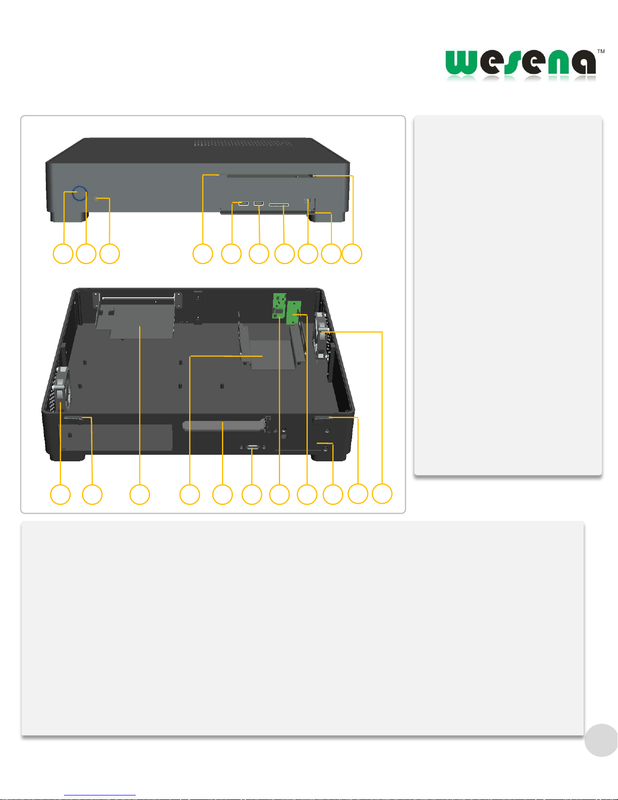
e5 overview
①. Power button
②. Power blue LED
③. IR Receive window
④. ODD button
⑤.USB port
⑥. Card reader
⑦. Latch of door
⑧. Card reader Door
⑨. Slot of ODD
⑩.60x60x15mm fan
⑪.top plate handle opening
⑫.ODD bracket
⑬.HDD bracket
⑭.PCI slot
⑮.eSATA Port
⑯.IR receiver
⑰. Power PCB board
⑱. PSU bay
4
Model: e5
Material: 100% full Aluminum
Color: Silver / black / Gold
Motherboard: Mini ITX / Micro ATX
HDD drive bay: 1X3.5”+1x2.5” or 2X3.5’’ HDD drive bay
ODD drive bay: an ultra-thin standard slot-in optical drive
Cooling: 2x60X60X15mm ultra-quiet fans
Expansion Slots: 1XStandard big PCI slot+ 1xeSATA port
Front I/O Port: 2x USB ports
Card Reader: Multi-card Reader
Dimension: 435mm×390mm×70mm (L×W×H)
Power Supply: Flex ATX PSU bay or 120W DC power
Remote control: Optional the MCE remote control built-in IR receiver
Net Weight: 4.2KG
Page 5
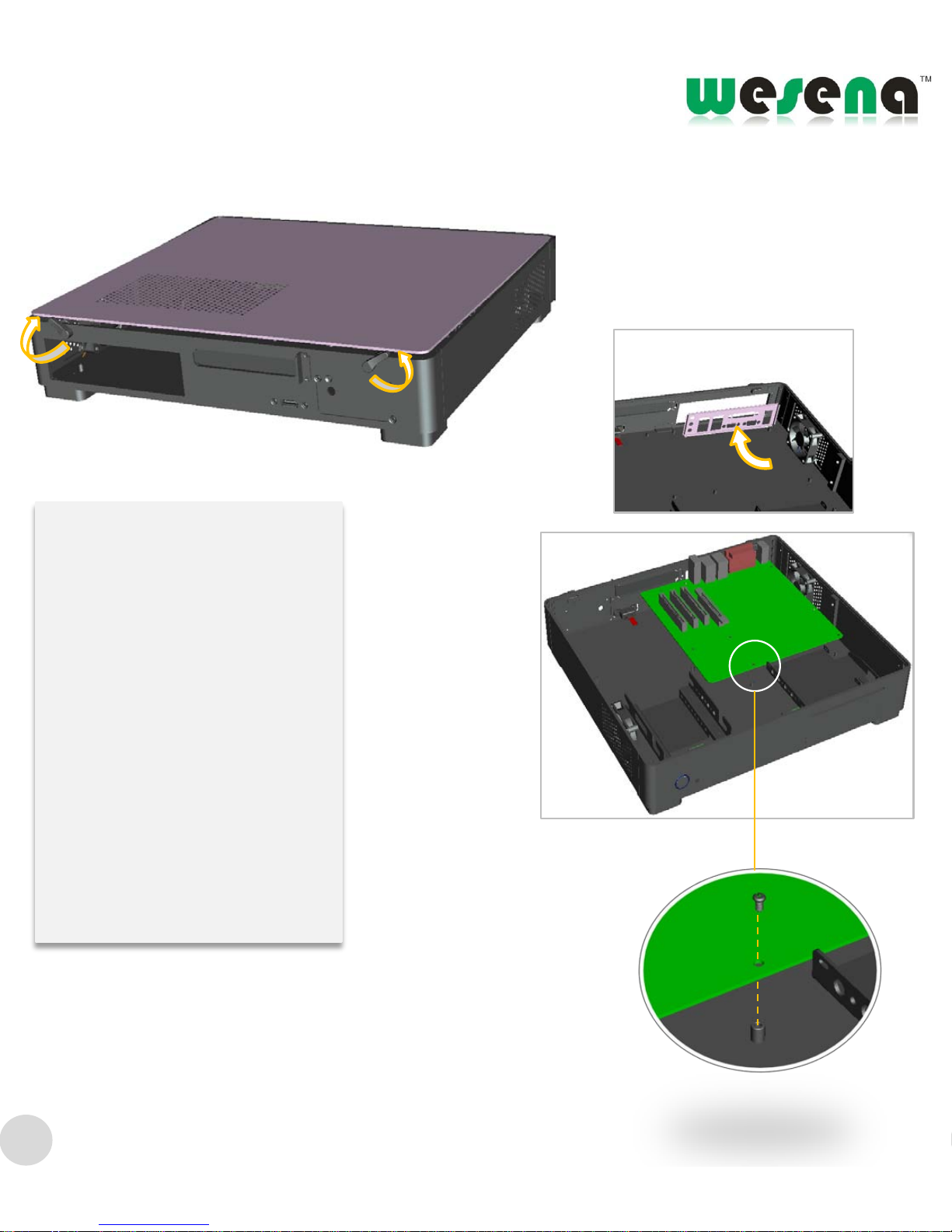
Open top plate
Rotating top plate , open the
handle and the top plate, take out
the top plate
Shown as photos
Motherboard installment
Put the I/O baffle plate firstly
Put the motherboard secondly,
alignment , and lock screws
Shown as photos
5
Page 6
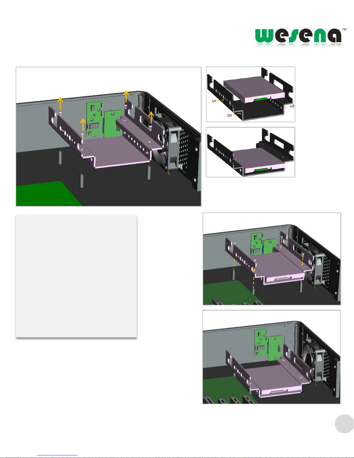
HDD installment
Unload HDD bracket screws, and
then take out the HDD bracket
Put the HDD with 2.5inch ,
alignment and lock the screws
Put the bracket, which has been
put 2.5inch HDD, into the right
place of the case. Alignment and
lock the screws
Shown as photos
6
Page 7
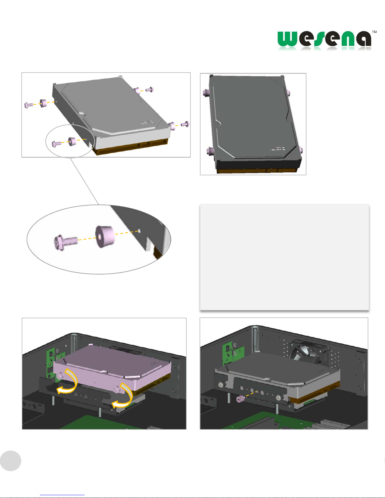
Take out the 3.5inch HDD screws, and the
anti-vibration pad ,and lock it to the both side
of the HDD( pay attention to the install way of
anti-vibration pad)
After lock the screws in both side of HDD, and
then put the HDD into the bracket. Shown as
the photos
Lock the screws manually
Shown as photos
7
Page 8
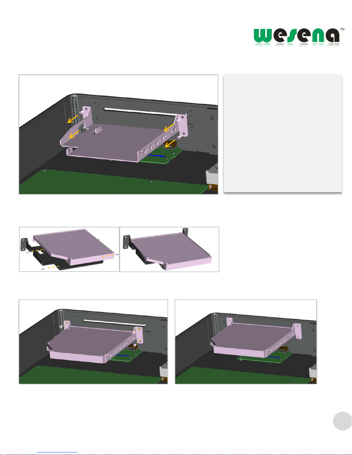
ODD installment
Unload screws, take out the ODD
bracket
Put the ODD on the ODD bracket,
and alignment ,lock the screws.
Shown as the photos
Put the bracket with ODD into the
case. Alignment and lock the
screws.
Shown as photos
8
Page 9
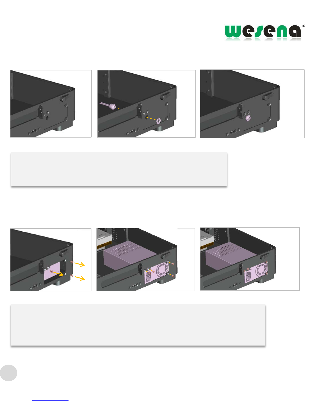
Power supply installment
Take off the nut , and then take out the power baffle plate. A nd then put the power into the
case. Alignment it and lock the nut.
Shown as photos
DC-DC power installment
Twist the DC power plug nut. Alignment it and lock the nut shown as photos
Shown as photos
9
Page 10
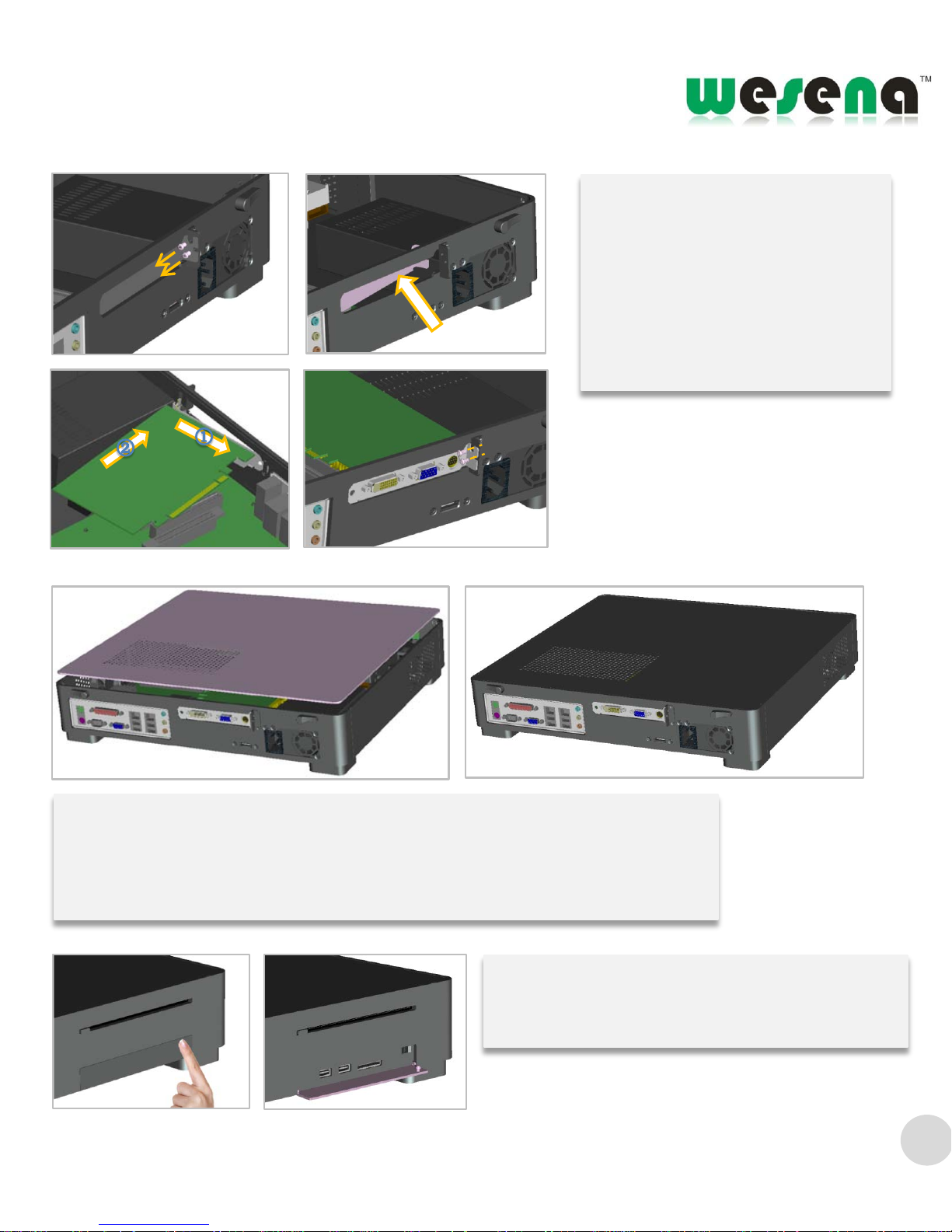
Cover the top plate
Check the installation position and connections agai n aft er finished the inner
installment, cover the plate lastly
Shown as photos
press top right corner of the card reader door to
open the card reader door
Shown as photos
PCI or PCIE expand installment
To exit 2 nuts firstly , and then
take out the baffle plate
Put the PCI or PCIE expand card
in. shown as photos.Lock the 2
screws
Shown as photos
10
Page 11
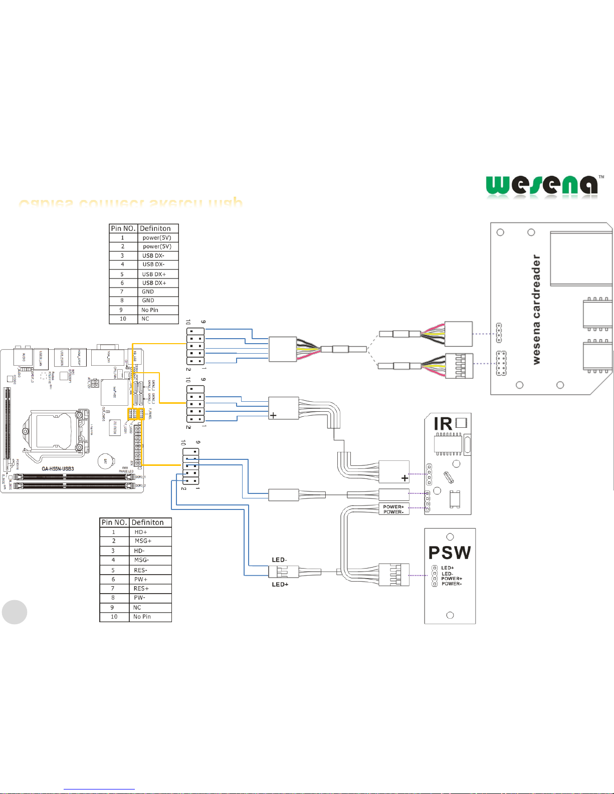
GA-H55N-USB3
motherboard
For example
②
④
⑥
⑧
USB
USB
USB
F-panel
F-panel
11
Cables connect sketch map
Page 12

Add: No. 809 8F A Area, Huameiju
Business Center, Xinhu Rd, Block
82 Baoan District Shenzhen, China
518102
Tel: +86 755 2919 3778 400 6088 126
Fax: +86 755 23494915
E- mail: [email protected]
http://www.wesena.com
 Loading...