

Page 1

WH2200/WH2500/WH3000 SERIES
Wood Attic Ladder
Installation Instructions
Escalera de ático de madera
Instrucciones de instalación
Échelle de grenier en bois
Instructions d'installation
THIS STAIRWAY IS DESIGNED FOR RESIDENTIAL USE ONLY.
READ THE INSTRUCTIONS COMPLETELY BEFORE STARTING. TWO PEOPLE ARE
REQUIRED FOR PROPER AND EASIER INSTALLATION.
FAILURE TO COMPLY WITH ALL INSTRUCTIONS MAY RESULT IN SERIOUS INJURY.
ESTA ESCALERA ESTÁ DISEÑADA SÓLO PARA USO RESIDENCIAL.
ANTES DE COMENZAR LEA TODAS LAS INSTRUCCIONES. SE NECESITAN DOS
PERSONAS PARA QUE LA INSTALACION SEA CORRECTA Y MAS FACIL.
SI NO SE CUMPLE CON TODAS LAS INSTRUCCIONES,
PUEDEN RESULTAR EN LESIONES GRAVES.
CETTE ÉCHELLE D’ÉCHELLE EST CONÇUE POUR UNE
UTILISATION RÉSIDENTIELLE UNIQUEMENT.
LISEZ CES INSTRUCTIONS COMPLÈTEMENT AVANT DE COMMENCER LE TRAVAIL. IL FAUT
DEUX PERSONNES POUR QUE L’INSTALLATION SOIT CORRECTE ET PLUS FACILE.
LE NON-RESPECT DE CES INSTRUCTIONS PEUT ENTRAÎNER UNE BLESSURE GRAVE
Page 2

Page 3
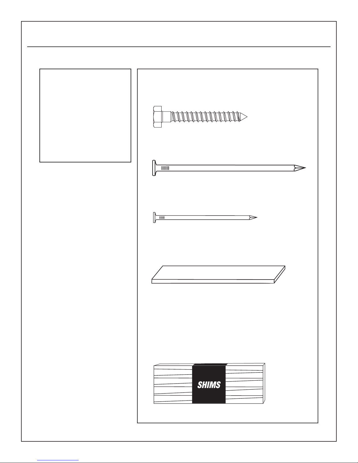
TOOLS AND MATERIALS NEEDED FOR INSTALLATION
TOOLS NEEDED:
Hammer
Ladder
Philips-head screwdriver
Slot-head screwdriver
Square
Tape Measure
Saw
ADDITIONAL MATERIALS NEEDED:
3" Lag Screws (optional)
16d Nails
8d Nails
1 x 4 temporary support slats (2
pieces approximately 32" long)
Braces with same
dimensions as joists
1/4" or 3/8" plywood for shims
Page 4
STEP 1:
BEFORE INSTALLATION:
Verify that this product and its installation meet all
applicable building codes. Check stair carefully
for shipping damage. Please mark the model
name and size of the stair you purchased on the
Installation Instructions for future reference. Keep
this instruction brochure with the installed stair. You
should have experience with squaring, leveling,
sawing, and aligning structural supports before
attempting to install this unit. If you do not have the
skills to install a window frame or door unit, please
hire a professional to install this stairway. Improper
installation could result in stairway collapse and
possible bodily injury.
STEP 3:
LOCATING THE STAIRWAY:
A. Measure and verify ceiling height (the distance
from the nished oor to the nished ceiling)
prior to beginning installation.
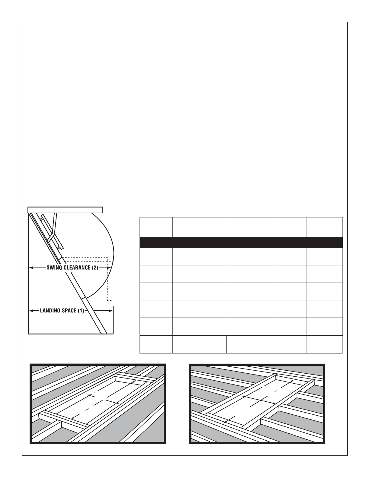
B. Allow sufficient area for a safe landing space
at the bottom of the stairway. Be sure there
is enough clearance for the swing of the stair as
it is being unfolded to its full length (see FIGURE 1
for “landing space” and “swing clearance”;
match the ceiling heights shown on the packing
carton with the same ceiling height in TABLE A to
determine proper landing space and swing
clearance requirements).
STEP 2:
INSPECTION OF MERCHANDISE:
DO NOT DISASSEMBLE STAIRWAY! MAKE SURE ALL
NUTS, BOLTS AND SCREWS ARE SECURELY FASTENED.
Remove cord and pull-handle from stairway, place
through hole in plywood door and knot the end.
Model #*
WH2208
WH2210
WH2508
WH2510
WH3008
FIGURE 1 - WOOD STAIRWAYS
WH3010
*Products sold in Canada will have model numbers ending in "CA".
STEP 4:
MAKING THE OPENING:
A. Cut the rough opening through the ceiling material as
shown in TABLE A.
B. Frame the rough opening to the size shown in TABLE A.
C. If it is necessary to cut ceiling joists. BE SURE to tie the
cut members to other joists with a header or stringer
brace of the same dimensions
(see FIGURES 2 and 3).
Rough
Opening
Ceiling Height Range
WH Series (Load Rating: 350lbs./159 kg)
22 ½" x 54"
(0.57 m x 1.37 m)
22 ½" x 54"
(0.57 m x 1.37 m)
25" x 54"
(0.64 m x 1.37 m)
25" x 54"
(0.64 m x 1.37 m)
30" x 54"
(0.76 m x 1.37 m)
30" x 54"
(0.76 m x 1.37 m)
84" - 105"
(2.30 m x 2.67 m)
105" - 124"
(2.67 m x 3.15 m)
84" - 105"
(2.30 m x 2.67 m)
105" - 124"
(2.67 m x 3.15 m)
84" - 105"
(2.30 m x 2.67 m)
105" - 124"
(2.67 m x 3.15 m)
Landing
Space (1)
56"
(1.42 m)
64"
(1.63 m)
56"
(1.42 m)
64"
(1.63 m)
56"
(1.42 m)
64"
(1.63 m)
Swing
Clearance (2)
62"
(1.57 m)
72"
(1.83 m)
62"
(1.57 m)
72"
(1.83 m)
62"
(1.57 m)
72"
(1.83 m)
TABLE A
STRINGER
STRINGER
BRACE
BRACE
HEADER
HEADER
BRACE
BRACE
NOTE: KEEP THE CORNERS SQUARE TO SIMPLIFY INSTALLATIONFIGURE 2 FIGURE 3
HEADER
BRACE
STRINGER
STRINGER
BRACE
BRACE
Page 5
STEP 5:
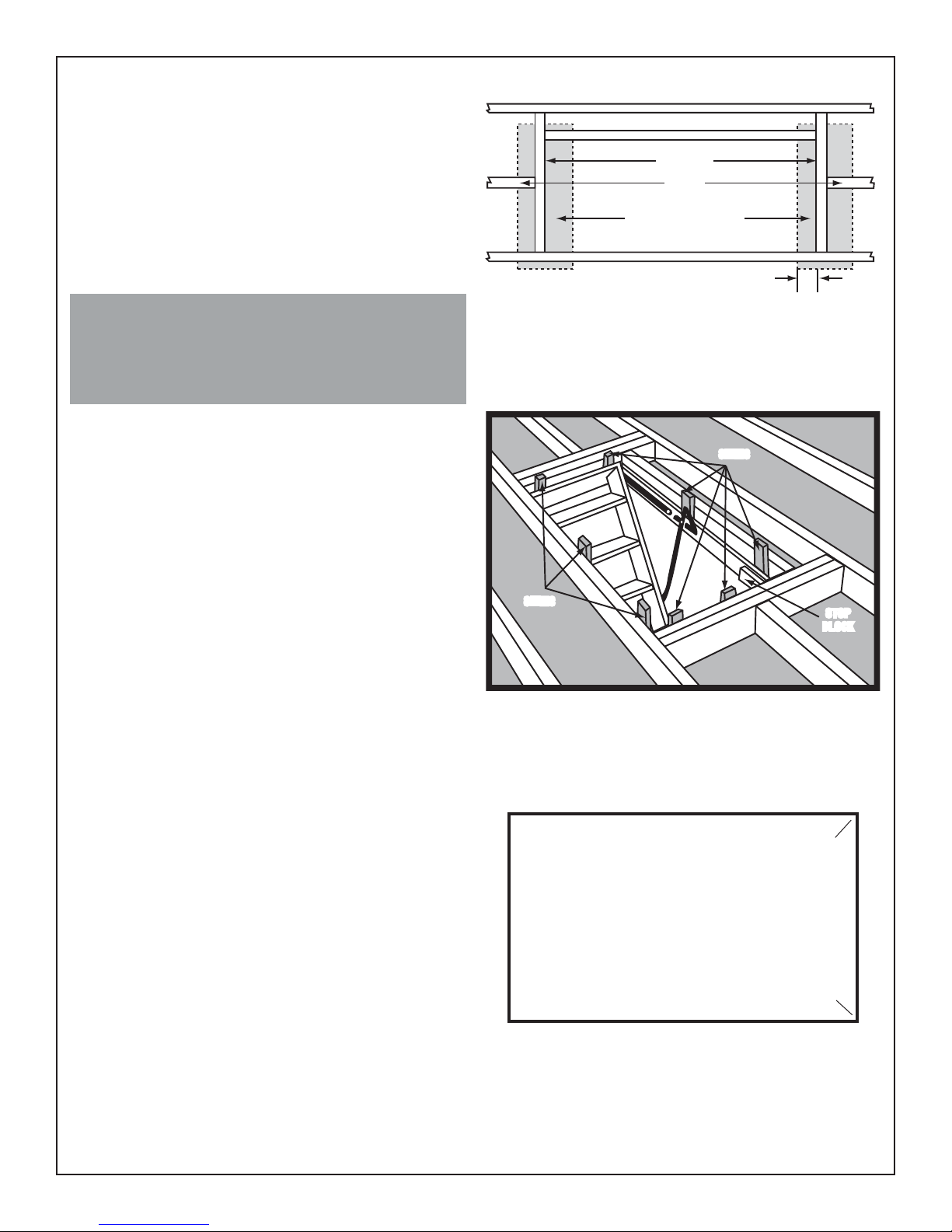
INSTALLING TEMPORARY SUPPORTS
It is necessary to temporarily support the stairway in the
prepared rough opening by using 1 x 4 slats that extend
from edge to edge across each end of the rough opening.
The slats form a ledge to support the stairway before it is
permanently secured. Care is important in positioning the
slats. Nail the slats below the ceiling onto the headers as
close to the edges of the rough opening as practical for
maximum strength. They should extend only 3/8" - 5/8"
(0.95 cm x 1.59 cm) into the rough opening. The plywood
panel must be free to swing open (see FIGURE 4).
CEILING JOIST
HEADERS
JOIST
TEMPORARY SUPPORTS
3/8" to 5/8" (0.95cm x 1.59cm)
The slats must be nailed securely enough to temporarily
support the weight of the stairway when it is placed in the rough
opening.
CAUTION: DO NOT PLACE ANY WEIGHT ON THE STAIRWAY
UNTIL PERMANENT NAILING IS COMPLETED
STEP 6:
PLACING STAIRWAY INTO OPENING
A. While closed, the stairway should now be raised into the
rough opening and positioned on the ledges formed by
the slats. Working above with a helper below, raise the
stairway through the rough opening at an angle so it will
clear the slats. Position the stairway in the rough opening.
DO NOT STAND ON OR OPEN THE STAIRWAY AT THIS
TIME. Make sure you have a helper below who can open
the stairway to allow completion of the installation.
B. Using at least three evenly spaced 8d nails per side,
temporarily affix the stairway in the opening by nailing,
at an angle, the well sides to the adjacent joists. Do not
drive these nails in all the way so they can be removed
later after the permanent nailing is completed.
C. Once the temporary nailing has been completed, have
your helper below open the stairway door panel and lower
the stair sections so that the area for permanent nailing is
exposed. DO NOT STAND ON THE STAIRWAY AT THIS
TIME.
STEP 7:
PERMANENT MOUNTING OF STAIRWAY
A. Be sure stairway is square and level in the rough opening.
If the stair frame has bowed while the stairway was in
inventory, nails and blocks of wood used as shims will
straighten it. Bowing is normal since wood parts are
subjected to strong spring tension for some time before
purchase and installation (see FIGURE 5).
B. Nail the sides (jambs) of the stairway frame to the rough
opening frame, using 16d nails or 3" lag screws. Holes
are provided in the pivot plates and piano hinge brackets.
Also nail through the end boards into the rough opening
headers. Complete permanent installation by using 16d
nails or 3" lag screws to secure stairway frame on all four
sides of the rough opening according to the diagram in
FIGURE 6. Use at least three evenly spaced fasteners on
each box end and at least ve evenly spaced fasteners on
each box side. Remove the 8d nails and the slats used
for temporary support.
FIGURE 4 - FRAMED OPENING WITH TEMPORARY
SUPPORT SLATS READY TO RECEIVE STAIRS
SHIMSSHIMS
SHIMSSHIMS
FIGURE 5
X
X
X
X
BOX SIDE
BOX END
X
PIVOT PLATE
X
PIVOT PLATE
X
BOX SIDE
X
- INDICATES RECOMMENDED LOCATION OF 16d NAILS 3" OR LAG SCREWS
X
FIGURE 6
X X
BLOCK
BLOCK
X
CORNER
BRACKET
CORNER
BRACKET
XX
STOP
STOP
HEADER
X
XX
Page 6

STEP 8:
CRITICAL STEP: Proper measurement and cutting of the ladder rails is important for
safe operation of your attic ladder. For instructional video, go to www.wernerladder.com.
ADJUSTING STAIRWAY TO CEILING HEIGHT
Pull stairway down applying pressure so that hardware arms are
fully extended. Open the stair sections, folding bottom section
under the middle section. The top and middle sections should
form a straight line. Aligning your ruler on the same plane as the
two upper sections, measure the distance from the bottom of the
middle section to the oor on the front and back (see FIGURE
7A). Mark the distances obtained on the front and back sides of
the ends of the bottom section.
Trim bottom sections at the proper length and angles by cutting
across them. With the bottom section cut to the proper length and
angle, joints will be tight at each section with weight on the stairs.
If either of the trim lines pass through any part of the
step, remove the 14 gauge nail between the rail-to-step
connection on both sides of ladder section. Once the
nail is removed, cut the rail ush to the underside of the
step on both sides of section (see FIGURE 7B). Gently
tap the tread side of the step with a hammer to remove
(see FIGURE 7C).
FIGURE 7B FIGURE 7C
Adjusting your stairway is
accomplished in 3 easy steps:
1. MEASURE 2. MARK 3. CUT
PIANO HINGE
BRACKETS
CUT ACCORDING
3
TO MEASUREMENT
TRIM LINE
FIGURE 7A - ADJUSTMENT TO CEILING HEIGHTS
PIVOT PLATE
B
A
B
A
MARK MEASUREMENTS ON BOTTOM
2
SECTION TO MAKE TRIM LINE
END BOARD
1
MEASURE THESE
DISTANCES
WARNING: The bottom section must t ush with the oor. Failure to cut properly could result in undue stress on the
component parts of the stairway, resulting in serious injury (see FIGURES 8A, 8B and 8C).
FIGURE 8B - INCORRECT SETUP FIGURE 8C - INCORRECT SETUPFIGURA 8A - CORRECT SETUP
STEP 9:
TRIMMING THE STAIRWAY OPENING
A. Select a molding that blends with the trim in your home: a
5/8" or 2-1/4" Clam Shell molding is a popular choice.
B. Leave a 3/8" space between the door panel and the trim
at the hinge end of the stairway to provide clearance
when the stairway is opened.
C. The balance of the trim may be placed approximately 1/8"
from the edges of the plywood door panel.
D. Your installation is complete.
CAUTION: SAFETY TIP
t.BLFDFSUBJOUIFTUBJSXBZJTBMJHOFE
properly before each use.
Page 7

HERRAMIENTAS Y MATERIALES REQUERIDOS PARA LA INSTALACION
HERRAMIENTAS
REQUERIDOS:
Martillo
Escalera
Destornillador para
tornillos cruciformes
Destornillador para tor-
nillos de ranura
Escuadra
Cinta métrica
Serrucho
MATERIALES ADICIONALES NECESARIOS:
Tornillos Tirafondo de 3 pulgs
Clavos 16d
Clavos 8d
Listones de 1 x 4 para sostén temporal
(2 piezas de 32 pulgs. de largo aproximadamente)
Puntales con las mismas
dimensiones que las viguetas
Madera contrachapada de 1/4 o 3/8 de pulg. para calzas
Page 8

PASO 1:
ANTES DE LA INSTALACIÓN:
Verique que este producto y su instalación cumplen
todos los códigos de construcción aplicables. Revise
cuidadosamente la escalera en busca de daño por
transporte. Por favor escriba el nombre de modelo y
el tamaño de la escalera que usted compró, en las
Instrucciones de Instalación, para futura consulta.
Mantenga este folleto de instrucciones con la
escalera instalada. Usted debe tener experiencia con
el escuadreo (instalación de elementos en ángulo
recto), nivelación, aserrado y alineación de soportes
estructurales, antes de intentar instalar esta unidad.
Si usted no tiene las habilidades para instalar un
marco de ventana o una puerta, por favor contrate
un profesional para que instale esta escalera. La
instalación inapropiada podría resultar en desplome
de la escalera y posible lesión corporal.
PASO 2:
INSPECCION DEL PRODUCTO:
¡NO DESARME LA ESCALERA! VERIFIQUE QUE TODAS LAS
TUERCAS, PERNOS Y TORNILLOS ESTEN BIEN APRETADOS.
Quite la cuerda y la borla de la escalera, hágala pasar
por el oricio en la puerta de madera contrachapada y
haga un nudo en el extremo.
PASO 3:
UBICACION DE LA ESCALERA:
A. Antes de comenzar la instalación, mida y verique
la altura del techo (cielo raso) (la distancia
entre el piso terminado y el techo terminado).
B. Deje un área suciente para el espacio para el
descanso seguro de la parte inferior de la escalera.
Verique que haya suciente espacio libre para
la oscilación de la escalera, cuando ésta sea
desdoblada a su longitud total (vea en la FIGURA 1
"espacio para descanso" y
; iguale las alturas del techo mostradas en la caja
giro"
de empaque con la misma altura del techo en la TABLA
A, para determinar los requerimientos correctos para
los espacios para descanso y
"espacio libre para
espacio libre para giro).
PASO 4:
PARA HACER LA ABERTURA:
A. Corte la abertura preliminar en el material del techo tal
como se muestra en la TABLA A.
B. Enmarque la abertura preliminar al tamaño mostrado en
TABLA A.
C. Si es necesario cortar viguetas del techo, CERCIORESE
de asegurar los miembros cortados a otras viguetas
con un puntal de travesaño o larguero de las mismas
dimensiones (vea las FIGURAS 2 y 3).
ESPACIO LIBRE
PARA GIRO (2)
ESPACIO PARA
DESCANSO (1)
FIGURA 1 - ESCALERA DE MADERA
TRAVESAÑO
LONGITUDINAL
Modelo #* Abertura preliminar
Rango de alturas del
cielo raso
Espacio para
aterrizaje (1)
Serie WH (Capacidad de carga: 350 lbs./159 kg)
WH2208
WH2210
WH2508
WH2510
WH3008
WH3010
Los productos que se venden en Canadá tendrán los números de modelo con
la terminación "CA".
22 ½" x 54"
(0.57 m x 1.37 m)
22 ½" x 54"
(0.57 m x 1.37 m)
25" x 54"
(0.64 m x 1.37 m)
25" x 54"
(0.64 m x 1.37 m)
30" x 54"
(0.76 m x 1.37 m)
30" x 54"
(0.76 m x 1.37 m)
84" - 105"
(2.30 m x 2.67 m)
105" - 124"
(2.67 m x 3.15 m)
84" - 105"
(2.30 m x 2.67 m)
105" - 124"
(2.67 m x 3.15 m)
84" - 105"
(2.30 m x 2.67 m)
105" - 124"
(2.67 m x 3.15 m)
TRAVESAÑO
LONGITUDINAL
56"
(1.42 m)
64"
(1.63 m)
56"
(1.342 m)
64"
(1.63 m)
56"
(1.42 m)
64"
(1.63 m)
Espacio libre
para giro (2)
62"
(1.57 m)
72"
(1.83 m)
62"
(1.57 m)
72"
(1.83 m)
62"
(1.57 m)
72"
(1.83 m)
TABLA A
TRAVESAÑO
CABECERO
NOTA: MANTENGA EN ÁNGULO RECTO LAS ESQUINAS PARA SIMPLIFICAR LA INSTALACIÓNFIGURA 2 FIGURA 3
TRAVESAÑO
CABECERO
Page 9

PASO 5:
INSTALACION DE LOS SOSTENES TEMPORALES
Es necesario sostener la escalera temporalmente dentro de la
abertura preliminar preparada, utilizando los listones de 1 x 4 que
se extienden de borde a borde a cada extremo de la abertura
preliminar. Los listones forman un resalto para sostener la
escalera antes que sea jada permanentemente. Es importante
tener cuidado al poner en posición los listones. Clave los listones
por debajo del techo a los travesaños tan cerca de los bordes
de la abertura preliminar como sea posible, para máxima
resistencia. Los listones deben sobresalir solamente de 3/8 a
5/8 de pulg. dentro de la abertura preliminar. El panel de madera
contrachapada debe quedar libre para poder oscilar y abrirse
(vea la FIGURA 4).
Los listones/tablillas deben asegurarse con clavos de manera
suficientemente firme para soportar temporalmente el peso de la
escalera cuando se coloque en la abertura preliminar.
PRECAUCIÓN: NO COLOQUE NINGÚN PESO SOBRE LA
ESCALERA HASTA FINALIZAR EL ASEGURAMIENTO
PERMANENTE CON CLAVOS
PASO 6:
COLOCACION DE LA ESCALERA
DENTRO DE LA ABERTURA
A. La escalera cerrada debe ser ahora levantada e introducida
dentro de la abertura preliminar y colocada en posición sobre
los resaltos formados por los listones. Trabajando por encima
con un ayudante por debajo, levante la escalera a través
de la abertura preliminar en ángulo para que pueda pasar
por los listones. Coloque la escalera en posición dentro de
la abertura preliminar. EN ESTE MOMENTO NO SE PARE
SOBRE LA ESCALERA NI LA ABRA. Asegúrese de que
tiene un ayudante debajo de la escalera para que pueda
abrirla y para terminar la instalación.
B. Utilizando varios clavos 8d, je la escalera temporalmente
dentro de la abertura clavando en ángulo los lados del
hueco a las viguetas adyacentes. No clave estos clavos
completamente para que se pueda sacarlos después que se
ha completado el clavado permanente.
C. Una vez que se ha completado el clavado temporal, instruya
a su ayudante que está debajo que quite los listones
temporales y que abra con cuidado el panel de la puerta de
la escalera, y que baje las secciones de la escalera de forma
que el área para el clavado permanente quede expuesto. NO
SE PARA SOBRE LA ESCALERA EN ESTE MOMENTO.
PASO 7:
MONTAJE PERMANENTE DE LA ESCALERA
A. Verique que la escalera está en escuadra y a nivel dentro
de la abertura preliminar. Si el marco de la escalera se
ha combeado mientras estaba almacenado, se lo puedo
enderezar con clavos y bloques de madera. El combeado es
normal debido a que las piezas de madera están sujetas a
la fuerte tensión del resorte durante un tiempo, antes de la
compra e instalación (vea la FIGURA 5).
B. Con los clavos 16d o con los tornillos tirafondos de 3 pulgados,
clave los lados (jambas) del marco de la escalera al marco de
la abertura preliminar. Se proveen oricios ya hechos en las
placas pivote y ménsulas de bisagra de piano. También clave
las tablas de los extremos dentro de los dinteles de la abertura
preliminar. Complete la instalación permanente clavando
sucientes clavos 16d para asegurar el marco de la escalera a
los cuatro lados de la abertura preliminar. Saque los clavos 8d
y los listones usados para sostén temporal.
VIGA DE CIELO RASO
CABECEROS
VIGA
SOPORTES TEMPORALES
3/8" to 5/8" (0.95 cm x 1.59 cm)
FIGURA 4 - ABERTURA ENMARCADA CON LISTONES DE SOPORTE
TEMPORAL LISTOS PARA RECIBIR LA ESCALERA
CALCES
CALCES
BLOQUE
DE TOPE
FIGURA 5
X
X
X
LADO DE CAJA
EXTREMO DE CAJA
X
X
PLACA DE PIVOTE
X
SOPORTE DE
ESQUINA
X
PLACA DE PIVOTE
X
LADO DE CAJA
X
- INDICA LA UBICACIÓN RECOMENDADA DE CLAVOS 16d
X
DE 3" ó TORNILLOS PARA MADERA
FIGURA 6
X X
SOPORTE DE
ESQUINA
XX
CABECERO
X
XX
Page 10

PASO 8:
PASO CRITICO: Medir y cortar correctament los rieles de la escalera es importante para la segura
operación de su escalera de atico. Para instrucciones en video, visite www.wernerladder.com.
AJUSTE DE LA ESCALERA A LA ALTURA DEL TECHO
Tire de la ecalera hacia abajo, aplicando presión para que los brazos
metálicos queden totalmente extendidos. Abra las secciones de la
escalera, doblando la sección inferior debajo de la sección del medio.
Las secciones superior y del medio deben formar una linea recta.
Alineando su regla al mismo plano de las dos secciones superiores,
mida la distancia desde la parte inferior de la sección del medio hasta
el piso, adelante y atrás (vea la FIGURA 7A). Marque las distancias
obtenidas de los lados de adelante y de atrás de los extremos de la
sección inferior.
Rebaje las secciones inferiores a la longitud y ángulos correctos
cortándolas transversalmente. Con la sección inferior cortada a la
longitud y ángulo correctos, las articulaciones estarán apretadas en
cada sección cuando haya peso sobre la escalera.
Si cualquiera de las líneas para recorte pasa a través
del cualquier parte del escalón, remueva el clavo calibre
14 entre la conexión de riel a peldaño en ambos lados
de la sección de escalera. Después de remover el clavo,
corte el riel a ras hasta el lado de abajo del peldaño en
ambos lados de la sección (vea la FIGURA 7B). Golpee
suavemente con un martillo el lado con huella del peldaño
para remover (vea la FIGURA 7C).
LÍNEA PARA RECORTE
FIGURA 7B FIGURA 7C
Ajustar su escalera se realiza a travez de los
siguientes 3 faciles pasos:
1. MIDA 2. MARQUE 3. CORTE
SOPORTES DE
BISAGRA TIPO
PIANO
CORTE DE ACUERDO
A LA MEDIDA
3
PLACA DE PIVOTE
B
A
MARQUE LAS MEDIDAS EN LA SECCION INFERIOR
2
B
PARA HACER LA LINEA DE CORTE
FIGURA 7A - AJUSTE DE ACUERDO A LAS ALTURAS
DEL CIELO RASO/TECHO
1
A
TABLA DE
EXTREMO
MIDA ESTAS
DISTANCIAS
ADVERTENCIA: La sección inferior debe apoyarse al ras con el piso. Si no es cortada correctamente, se podrían aplicar
esfuerzos indebidos a las piezas componentes de la escalera, y causar lesiones graves (vea las FIGURAS 8A, 8B y 8C).
SEPARACIÓN
LAS PATAS ESTÁN A
RAS CON EL PISO
FIGURA 8A
INSTALACIÓN CORRECTA
NO HAY
SEPARACIÓN
INSTALACIÓN INCORRECTA
SEPARACIÓNNO HAY
LAS PATAS NO ESTÁN A
RAS CON EL PISO
FIGURA 8B
SEPARACIÓN
LAS PATAS NO ESTÁN A
RAS CON EL PISO
FIGURA 8C
INSTALACIÓN INCORRECTA
PASO 9:
MONTAJE DE CONTRAMARCOS EN LA ABERTURA DE LA ESCALERA
A. Escoja una moldura que combine con las molduras en su casa: una moldura de 5/8
o 2-1/4 pulgadas Clam Shell (almeja) es una selección popular.
B. Deje un espacio de 3/8 de pulgada entre el panel de la puerta y la moldura en el
lado de las bisagras de la escalera, para proveer el espacio libre cuando se abre la
escalera.
C. El resto de la moldura puede ser colocado aproximadamente a 1/8 de pulgada de
los bordes del panel de la puerta de madera contrachapada.
D.
Su instalación está nalizada.
t"OUFTEFDBEBVTPDFSDJØSFTF
de que la escalera esté alineada
correctamente.
PRECAUCION:
CONSEJO DE SEGURIDAD
Page 11

OUTILS ET MATÉRIAUX NÉCESSAIRES POUR L'INSTALLATION
OUTILS NÉCESSAIRES :
Marteau
Échelle
Tournevis à pointe Philips
Tournevis pour vis à tête
mortaisée
Équerre
Mètre à ruban
Scie
MATÉRIAUX ADDITIONNELS NÉCESSAIRES :
Tire-fond de 3" (optionnel)
Clous 16d
Clous 8d
Planchettes de support temporaire de 1 x 4 (2 morceaux de
longueur 32" ou 81 cm environ)
Renforts de mêmes dimensions que les solives
Contreplaqué de 1/4" ou 3/8" pour faire des cales
Page 12

ÉTAPE 1 :
AVANT L’INSTALLATION :
Vériez que ce produit et son installation sont conformes
à toutes les normes de construction applicables.
Vériez l’échelle d’échelle soigneusement pour déceler
d’éventuels dommages par le transport. Veuillez
noter le nom du modèle et la taille de cette échelle
achetée sur son document d’instructions d’installation
comme référence ultérieure. Conservez ce document
d’installation sur le lieu du produit installé. Vous devez
avoir suffisamment d’expérience d’équerrage, de mise à
niveau, de sciage et d’alignement de supports structurels
avant de tenter d’installer cette unité. Si vous n’avez
pas les compétences pour installer un encadrement de
fenêtre ou de porte, veuillez embaucher un professionnel
pour installer cette échelle d’échelle. Une installation
incorrecte pourrait résulter en un effondrement de
l’échelle et de possibles blessures corporelles.
ÉTAPE 2 :
INSPECTION DE LA MARCHANDISE :
NE DÉMONTEZ PAS L’ÉCHELLE! ASSUREZ-VOUS QUE
L’ENSEMBLE DES ÉCROUS, BOULONS ET VIS EST BIEN SERRÉ.
Enlevez le cordon et la poignée de tirage de l’échelle,
placez-les au travers du trou dans la trappe en contreplaqué et faites un nœud à l’extrémité.
ÉTAPE 4 :
LOCALISATION DE L’ÉCHELLE :
A. Mesurez et vériez la hauteur de plafond (la distance
entre la nition de plancher et la nition de plafond)
avant de commencer l’installation.
B. Prévoyez une zone suffisante pour un espace de contact
d’arrivée au sol en bas de l’échelle. Assurez-vous qu’il y
a assez d’espacement pour le déploiement de l’échelle
quand il est déplié sur toute sa longueur (Voir la FIGURE
1 pour l’espace de contact et la projection ; comparez les
hauteurs de plafond montrées sur le carton d’emballage
avec la même hauteur de plafond au TABLEAU A, pour
déterminer les besoins adéquats en espace de contact
au sol et en projection).
ÉTAPE 4 :
RÉALISATION DE L’OUVERTURE :
A. Découpez l’ouverture brute dans le matériau du plafond
comme montré au TABLEAU A.
B. Dimensionnez l’ouverture brute à la taille montrée au
Tableau A.
C. S’il est nécessaire de couper des solives du plafond : NE
MANQUEZ PAS de xer les membres coupés à d’autres
solives avec un chevêtre ou un tirant comme renfort, des
mêmes dimensions (Voir les FIGURES 2 et 3).
RAYON DE ROTATION (2)
ESPACE DE CONTACT (1)
FIGURE 1 – ÉCHELLES EN BOIS
N° de
modèle
Ouverture
brute
Plage de hauteur
de plafond
Espace de
contact (1)
Série WH (Classification de charge : 350 lbs./159 kg)
WH2208
WH2210
WH2508
WH2510
WH3008
WH3010
Les numéros de modèles de produits vendus au Canada se termineront par "CA".
22 ½" x 54"
(0.57 m x 1.37 m)
22 ½" x 54"
(0.57 m x 1.37 m)
25" x 54"
(0.64 m x 1.37 m)
25" x 54"
(0.64 m x 1.37 m)
30" x 54"
(0.76 m x 1.37 m)
30" x 54"
(0.76 m x 1.37 m)
84" - 105"
(2.30 m x 2.67 m)
105" - 124"
(2.67 m x 3.15 m)
84" - 105"
(2.30 m x 2.67 m)
105" - 124"
(2.67 m x 3.15 m)
84" - 105"
(2.30 m x 2.67 m)
105" - 124"
(2.67 m x 3.15 m)
56"
(1.42 m)
64"
(1.63 m)
56"
(1.42 m)
64"
(1.63 m)
56"
(1.42 m)
64"
(1.63 m)
Rayon de
rotation (2)
62"
(1.57 m)
72"
(1.83 m)
62"
(1.57 m)
72"
(1.83 m)
62"
(1.57 m)
72"
(1.83 m)
TABLEAU A
STRINGER
RENFORT
BRACE
PAR TIRANT
HEADER
RENFORT PAR
BRACE
CHEVÊTRE
REMARQUE : GARDEZ LES ANGLES BIEN D’ÉQUERRE POUR SIMPLIFIER L’INSTALLATION FIGURE 3FIGURE 2 FIGURE 3
STRINGER
RENFORT PAR
BRACE
HEADER
RENFORT PAR
BRACE
CHEVÊTRE
TIRANT
Page 13

ÉTAPE 5 :
INSTALLATION DE SUPPORTS TEMPORAIRES :
Il est nécessaire de supporter temporairement l’échelle dans
l’ouverture brute préparée en utilisant des planchettes de 1 x 4"
de section, qui s’étendent de bord à bord en travers de chaque
extrémité de l’ouverture brute. Ces planchettes forment des appuis
pour supporter l’échelle avant qu’elle soit xée de façon permanente.
Il est important de positionner soigneusement les planchettes.
Clouez les planchettes sous le plafond dans les chevêtres aussi
près des bords de l’ouverture brute que possible en pratique pour
avoir une résistance maximale. Elles ne doivent dépasser que de
3/8" - 5/8" (9.5 - 15.9 mm) dans l’ouverture brute. Le panneau en
contreplaqué doit pouvoir s’ouvrir librement (Voir la FIGURE 4).
SOLIVE DE PLAFOND
CHEVÊTRES
SOLIVE
SUPPORTS
TEMPORAIRES
3/8 x 5/8" (0.95 x 1.59 cm)
Les planchettes doivent être clouées assez bien pour supporter
temporairement le poids de l’échelle quand il est placé dans l’ouverture
brute.
ATTENTION : NE PLACEZ AUCUNE CHARGE SUR L’ÉCHELLE AVANT
QUE SON CLOUAGE PERMANENT SOIT TERMINÉ.
ÉTAPE 6 :
PLACEMENT DE L’ÉCHELLE DANS L’OUVERTURE
A. En étant fermée, l’échelle doit maintenant être hissée dans
l’ouverture brute et positionnée sur les appuis formés par
les planchettes. En travaillant au-dessus avec une aide en
dessous, levez l’échelle au travers de l’ouverture brute avec
une inclinaison de façon à passer les planchettes. Positionnez
l’échelle dans l’ouverture brute.
NE VOUS TENEZ PAS SUR L’ÉCHELLE, OU NE L’OUVREZ
PAS À CE STADE. Assurez-vous que votre aide en bas pourra
ouvrir l’échelle pour permettre de terminer l’installation.
B. En utilisant au moins trois clous 8d espacés régulièrement sur
chaque côté, xez temporairement l’échelle dans l’ouverture en
clouant avec un angle les côtés du puits aux solives adjacentes.
N’enfoncez pas complètement ces clous, pour pouvoir les
enlever aisément plus tard après le clouage permanent.
C. Une fois que ce clouage temporaire est ni, demandez à
votre aide en bas d’ouvrir le panneau de trappe de l’échelle
et d’abaisser ses sections de sorte que la zone pour le
clouage permanent soit exposée. NE VOUS TENEZ PAS SUR
L’ÉCHELLE À CE STADE.
ÉTAPE 7 :
MONTAGE PERMANENT DE L’ÉCHELLE
A. Assurez-vous que l’échelle est bien d’équerre et de niveau dans
l’ouverture brute. Si le cadre de l’échelle a travaillé pendant
que l’échelle était en inventaire, des clous et des blocs de bois
utilisés comme cales vont le redresser. Du cintrage est normal
car les pièces en bois sont soumises à une forte tension de
ressort pendant un certain temps entre l’achat et l’installation
(Voir la FIGURE 5).
B. Clouez les côtés (montants) du cadre d’échelle sur
l’encadrement de l’ouverture brute, en utilisant des clous 16d
ou des tire-fond de 3". Des trous sont fournis dans les plaques
de pivotement et les supports de charnières à piano. Clouez
aussi au travers des planches d’extrémité dans les linteaux de
l’ouverture brute. Complétez l’installation permanente en utilisant
des clous 16d ou des tire-fond de 3" pour xer le cadre d’échelle
sur les quatre côtés de l’ouverture brute selon le diagramme
de la FIGURE 6. Utilisez au moins trois xations espacées
régulièrement sur chaque extrémité de boîte, et au moins cinq
xations espacées régulièrement sur chaque côté de boîte.
Enlevez les clous 8d plantés et les planchettes utilisées comme
support temporaire.
FIGURE 4 – OUVERTURE ENCADRÉE AVEC PLANCHETTES DE SUPPORT TEM-
CALESCALES
PORAIRE PRÊTE À RECEVOIR L’ÉCHELLE
CALESCALES
FIGURE 5
BLOC
BLOC
D’ARRÊT
D’ARRÊT
X
X
X
CÔTÉ DE BOÎTE
EXTRÉMITÉ DE BOÎTE
X
X
CÔTÉ DE BOÎTE
X
X
X
- INDIQUE L’EMPLACEMENT RECOMMANDÉ POUR LES CLOUS
X
PLAQUE DE PIVOTEMENT
PLAQUE DE PIVOTEMENT
X X
16D OU LES TIRE-FOND 3"
FIGURE 6
X
SUPPORT
D’ENCOIGNURE
EXTRÉMITÉ DE BOÎTE
SUPPORT
D’ENCOIGNURE
XX
X
XX
Page 14

ÉTAPE 8 :
ÉTAPE CRITIQUE : Une mesure et une coupe appropriées des montants de l’échelle sont importantes pour un
fonctionnement sûr de votre échelle de grenier. Pour visionner une vidéo d’instructions, allez sur le site www.wernerladder.com.
AJUSTAGE DE L’ÉCHELLE À LA HAUTEUR DU PLAFOND
Tirez en appliquant une pression an que les bras mécaniques soient
complètement déployés. Ouvrez les sections de l’échelle, en pliant la
section inférieure sous la section du milieu. Les sections supérieure et
du milieu doivent être alignées. Alignez votre mètre à ruban sur le même
plan que les deux sections du haut, mesurez la distance restante entre
le bas de la section du milieu et le plancher à l’avant et à l’arrière (Voir
la FIGURE 7A). Marquez les distances obtenues sur les côtés avant et
arrière des extrémités de la section du bas.
Coupez les sections du bas à la longueur appropriée et en biseau en
travers. La section du bas ayant été coupée avec les longueurs et l’angle
de coupe adéquats, les jonctions doivent être serrées à chaque section
avec une charge sur l’échelle.
Si l’une des lignes de découpe passe par une quelconque
partie de marche, enlevez le clou de 14 entre la connexion de
montant sur marche, des deux côtés de la section d’échelle.
Une fois ce clou ôté, coupez le montant au niveau de la face
inférieure de la marche des deux côtés de section (Voir la
FIGURE 7B). Frappez doucement le côté avec lets de la
marche avec un marteau pour l’enlever (Voir la FIGURE 7C).
FIGURE 7B FIGURE 7C
Le réglage de votre échelle se fait en
3 étapes faciles :
1. MESURE 2. MARQUAGE 3. COUPE
SUPPORTS DE
CHARNIÈRES À PIANO
COUPEZ SELON LES
3
MESURES
LIGNE DE COUPE
FIGURE 7A - AJUSTEMENT AUX HAUTEURS DE PLAFONDS
PLAQUE DE PIVOTEMENT
B
A
B
A
ARQUEZ LES MESURES SUR LA
2
SECTION DU BAS POUR TRACER UNE
LIGNE DE RACCOURCISSEMENT
PLANCHE
D’EXTRÉMITÉ
1
MESUREZ CES
DISTANCES
AVERTISSEMENT : La section du bas doit arriver pile au plancher. Le fait de ne pas couper correctement peut entraîner une contrainte
anormale sur les parties constitutives de l’échelle, et provoquer une blessure grave (Voir les FIGURES 8A, 8B et 8C).
PAS D’INTERVALLE
PAS D’INTERVALLE
LES PIEDS SONT
AU NIVEAU DU
PLANCHER
FIGURE 8B – MISE EN PLACE INCORRECTE FIGURE 8C – MISE EN PLACE INCORRECTEFIGURE 8 – MISE EN PLACE CORRECTE
INTERVALLE
LES PIEDS SONT
AU NIVEAU DU
PLANCHER
INTERVALLE
LES PIEDS SONT
AU NIVEAU DU
PLANCHER
ÉTAPE 9 :
HABILLAGE DE L’OUVERTURE D’ÉCHELLE
A. Sélectionnez une moulure qui soit assortie avec celles dans votre
maison : une moulure double face de 5/8" ou 2-1/4" est un choix
populaire.
B. Laissez un espace de 3/8" entre le panneau de trappe et la gar-
niture à l’extrémité de charnière de l’échelle, pour laisser la place
nécessaire quand l’échelle est ouvert.
C. Le centrage de la garniture peut être placé à environ 1/8" des bords
du panneau de trappe en contreplaqué.
D. Votre installation est terminée.
ATTENTION : CONSEILS DE SÉCURITÉ
t$POUSÙMF[RVFMÏDIFMMFFTUDPSSFDUFNFOU
alignée avant chaque utilisation.
Page 15

Page 16

Werner Co.
93 Werner Rd.
Greenville, PA 16125-9499
Werner Access Products Canada, ULC
60 Admiral Blvd.
Mississauga, ON L5T 2W1
Telephone/Teléfono/Téléphone:
(U.S.) 888-523-3370
(Canada) 877-553-7004
www.wernerladder.com/atticladder
PN104366-01 Rev A 10/11 ©2011 Werner Co.
 Loading...