

Page 1
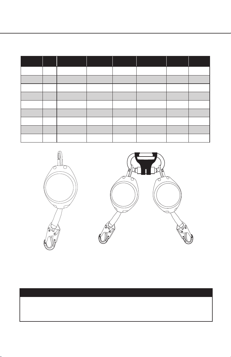
Appendix D BaseLine™ Self Retracting Lifelines
USER INSTRUCTIONS
Model Length
R530007 7 ft 36 inches 900 pounds
R530007-R 7 ft 36 inches 900 pounds
R530007-SR 7 ft 36 inches 900 pounds
R531007 7 ft 36 inches 900 pounds
R531007-R 7 ft 36 inches 900 pounds
R531007-SR 7 ft 36 inches 900 pounds
R530011 11 ft 36 inches 900 pounds
R530011-R 11 ft 36 inches 900 pounds
R530011-SR 11 ft 36 inches 900 pounds
Maximum
Arrest Distance
Average
Arrest Force
ANSI
Standard
Z359.14-2014
Class B
Z359.14-2014
Class B
Z359.14-2014
Class B
Z359.14-2014
Class B
Z359.14-2014
Class B
Z359.14-2014
Class B
Z359.14-2014
Class B
Z359.14-2014
Class B
Z359.14-2014
Class B
Lifeline
1 inch Dyneema
Webbing
1 inch Dyneema
Webbing
1 inch Dyneema
Webbing
1 inch Dyneema
Webbing
1 inch Dyneema
Webbing
1 inch Dyneema
Webbing
1 inch Dyneema
Webbing
1 inch Dyneema
Webbing
1 inch Dyneema
Webbing
®
®
®
®
®
®
®
®
®
Lifeline
Hook
Steel
Snap Hook
Aluminum
Rebar Hook
Steel
Rebar Hook
Steel
Snap Hook
Aluminum
Rebar Hook
Steel
Rebar Hook
Steel
Snap Hook
Aluminum
Rebar Hook
Steel
Rebar Hook
Rated
Capacity
310 pounds
310 pounds
310 pounds
310 pounds
310 pounds
310 pounds
310 pounds
310 pounds
310 pounds
Twin LegSingle Leg
NOTE: Werner Fall Protection BaseLine™ Self-Retracting Lifeline
models must NOT be used in Leading Edge applications.
ALWAYS keep lifeline from contacting sharp or abrasive edges
and surfaces.
WARNING:
ALL components of the personal fall arrest system must be selected and
determined to be suitably compatible with Werner BaseLine™ SRL by a
Competent Person.
Page 1
ENGLISH
Page 2
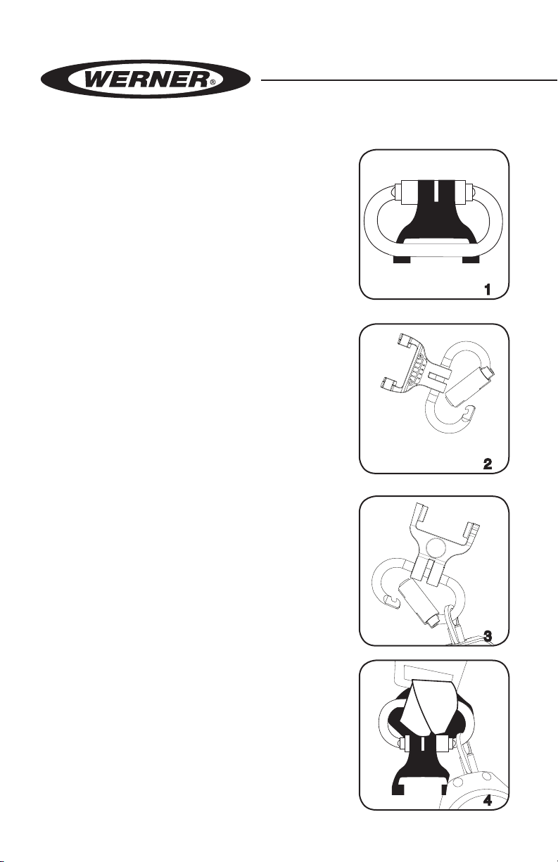
DUAL-LEG CONFIGURATIONS:
2
0
1
7
19
1
8
1
5
1
6
1
2
1
1
1
0
3
2
1
9
8
7
6
5
4
1. When using dual leg SRL
con guration, make sure to maintain
100% tie-off at all times. ALWAYS
maintain one engaged snap hook
or rebar hook attached to an
appropriate anchorage connector,
while hooking disengaged snap
hook or rebar hook.
2. Unclip plastic keeper and slip it off
gate. See gures 1 and 2.
3. Open gate and connect rst SRL
unit. Move connection point around
connector. See gure 3.
ENGLISH
Page 2
4. Hook connector around both
webbing straps on the back plate:
follow the path of the back D-ring.
See gure 4.
Page 3

Appendix D BaseLine™ Self Retracting Lifelines
USER INSTRUCTIONS
5. With rst SRL unit and webbing in
place, connect second SRL unit.
See gure 5.
6. Reposition the plastic keeper,
locating SRL units and webbing in
each respective slot. See gure 6.
7. ONLY use with Werner Fall
Protection Self Retracting Lifelines
designed to be back mounted.
HORIZONTAL SYSTEMS:
Applications where the SRL is used horizontally or with a horizontal
system, the SRL and horizontal system components must be
compatible. Both the horizontal and vertical distances are required
for clearance calculations. Horizontal systems must be designed
and installed under the supervision of a quali ed person.
prior to use and follow accordingly. If missing, contact
Werner Co. for a replacement. Inspect product prior to each
use, then at least monthly by a competent person who is not a user.
Before use withdraw and retract some webbing and tug sharply to
ensure that the pawls engage properly and the unit retracts normally.
Avoid exposure to sharp edges, chemicals, or environmental hazards that
could weaken the product. User repairs or alterations are NOT permitted.
Only the harness back D-ring (A) to be used for fall arrest. Verify connectors are
compatible (see User Manual). Ensure that the anchorage strength is
5,000 lbs. (22kN) or more, or certified by a Qualified Person to take
twice the foreseeable load. To minimize swing fall, anchor as directly
above work area as possible. Check for unobstructed clearance
beneath. Do not permit the lifeline to become slack. Verify that this
product is suitable for the chosen fall protection. See instructions
for suitability for horizontal use and horizontal lifeline compatibility
If the stitching is torn, this indicates that the product has seen a
fall and should be removed from service. See the User Manual for
more details. User must be trained before using this product.
Read all warnings and instructions in User Manual
© 2016 Werner Co.
P/N 108727-04 Rev B 10/16
ENGLISH
Page 3
Page 4

BASELINE
SELF RETRACTING LIFELINE
Model:
R530007-SR
7 feet
Standard Code
OSHA 1910 & 1926
Mk 1
P/N108726-05
Rev B 5/17
Lifeline Length:
Material-Diameter/Width & Thickness:
Dyneema Webbing 1" Wide x .07" Thick
Average Arrest Force: 900 lbs.
Arrest Distance: 36"
Maximum User Weight: 310 lbs.
Z359.14-2014 Class B
Page 4
™
Inspection Log
Year 1 Year 2 Year 3 Year 4 Year 5
BASELINE
™
SELF RETRACTING LIFELINE
Model:
R530011-SR
Lifeline Length:
Material-Diameter/Width & Thickness:
Dyneema Webbing 1" Wide x .07" Thick
Average Arrest Force: 900 lbs.
1
2
3
4
5
6
7
8
9
10
11
12
Arrest Distance: 36"
Maximum User Weight: 310 lbs.
Standard Code
Z359.14-2014 Class B
OSHA 1910 & 1926
Mk 1
11 feet
P/N108726-06
Rev B 5/17
Inspection Log
Year 1 Year 2 Year 3 Year 4 Year 5
1
2
3
4
5
6
7
8
9
10
11
12
PN105815-10 ©2017 Werner Co. Rev G 5/17
Page 5

Anexo D - Cuerdas Salvavidas
Auto-Retráctiles BaseLine
INSTRUCCIONES PARA EL USUARIO
™
Modelo Longitud
R530007
R530007-R
R530007-SR
R531007
R531007-R
R531007-SR
R5300011
R5300011-R
R5300011-SR
7 pies
(2.15 m)
7 pies
(2.15 m)
7 pies
(2.15 m)
7 pies
(2.15 m)
7 pies
(2.15 m)
7 pies
(2.15 m)
11 pies
(3.38 m)
11 pies
(3.38 m)
11 pies
(3.38 m)
Distancia de
detención máxima
36 pulgadas
(914 mm)
36 pulgadas
(914 mm)
36 pulgadas
(914 mm)
36 pulgadas
(914 mm)
36 pulgadas
(914 mm)
36 pulgadas
(914 mm)
36 pulgadas
(914 mm)
36 pulgadas
(914 mm)
36 pulgadas
(914 mm)
Fuerza de
detención
900 libras
(4 kN) Prom
900 libras
(4 kN) Prom
900 libras
(4 kN) Prom
900 libras
(4 kN) Prom
900 libras
(4 kN) Prom
900 libras
(4 kN) Prom
900 libras
(4 kN) Prom
900 libras
(4 kN) Prom
900 libras
(4 kN) Prom
Norma ANSI
cumplida
Z359.14-2014
Clase B
Z359.14-2014
Clase B
Z359.14-2014
Clase B
Z359.14-2014
Clase B
Z359.14-2014
Clase B
Z359.14-2014
Clase B
Z359.14-2014
Clase B
Z359.14-2014
Clase B
Z359.14-2014
Clase B
Cuerdas
salvavidas
®
Dyneema
1 pie (25 mm)
®
Dyneema
1 pie (25 mm)
®
Dyneema
1 pie (25 mm)
®
Dyneema
1 pie (25 mm)
®
Dyneema
1 pie (25 mm)
®
Dyneema
1 pie (25 mm)
®
Dyneema
1 pie (25 mm)
®
Dyneema
1 pie (25 mm)
®
Dyneema
1 pie (25 mm)
Cuerdas salvavidas
gancho
acero
mosquetón
aluminio gancho
estructura
acero gancho
estructura
acero
mosquetón
aluminio gancho
estructura
acero gancho
estructura
acero
mosquetón
aluminio gancho
estructura
acero gancho
estructura
Capacidad
nominal
310 libras
(141 kg)
310 libras
(141 kg)
310 libras
(141 kg)
310 libras
(141 kg)
310 libras
(141 kg)
310 libras
(141 kg)
310 libras
(141 kg)
310 libras
(141 kg)
310 libras
(141 kg)
Pata doblePata única
NOTA: Los modelos de cuerdas salvavidas auto-retráctiles BaseLine™
de protección contra caídas de Werner NO se deben utilizar
en aplicaciones de borde delantero. SIEMPRE evite que la
cuerda salvavidas haga contacto con bordes y super cies
losos o abrasivos.
ADVERTENCIA:
TODOS los componentes del sistema personal de detención de caídas
deben ser seleccionados y determinados como compatibles con la
cuerda salvavidas auto-retráctil BaseLine™ de Werner por parte de una
persona competente.
Página 5
ESPAÑOL
Page 6

CONFIGURACIONES DE PATA DOBLE:
2
0
1
7
19
1
8
1
5
1
6
1
2
1
1
1
0
3
2
1
9
8
7
6
5
4
1. Al utilizar la con guración de cuerda
salvavidas auto-retráctil de pata
doble, asegúrese de mantener el
100% de amarre en todo momento.
SIEMPRE mantenga un gancho de
cierre resortado o un gancho para
barra de refuerzo conectado a un
conector de ancladero apropiado,
mientras engancha el otro gancho
de cierre resortado o gancho para
barra de refuerzo.
2. Libere la abrazadera plástica y
deslícela fuera de la puerta. Vea las
guras 1 y 2.
3. Abra la puerta y conecte la primera
unidad de cuerda salvavidas autoretráctil. Mueva el punto de conexión
alrededor del conector. Vea la gura
3.
ESPAÑOL
Página 6
4. Enganche el conector alrededor de
ambas correas tejidas en la placa
de espalda: siga la trayectoria del
anillo en “D” de espalda. Vea la
gura 4.
Page 7

Anexo D - Cuerdas Salvavidas
Auto-Retráctiles BaseLine
INSTRUCCIONES PARA EL USUARIO
5. Con la primera unidad de cuerda
salvavidas auto-retráctil y correas
tejidas en su sitio, conecte la
segunda unidad de cuerda
salvavidas auto-retráctil. Vea la
gura 5.
6. Posicione nuevamente la
abrazadera plástica, colocando las
unidades de cuerdas salvavidas
auto-retráctiles y correas tejidas
en cada ranura respectiva. Vea la
gura 6.
™
7. SOLO utilice cuedas salvavidas auto-retractiles de marca
Werner, diseñados para ser montado en la espalda.
Sistemas horizontales
Aplicaciones donde se utiliza el SRL horizontalmente o con un
sistema horizontal, el SRL y los componentes del sistema horizontal
deben ser compatibles. Las distancias horizontal y vertical, ambas
son requeridas para los cálculos de espacio libre. Sistemas
horizontales deben ser diseñados e instalados bajo la supervisión
de una persona cuali cada.
ESPAÑOL
Página 7
Page 8

ESPAÑOL
Página 8
PN105815-10 ©2017 Werner Co. Rev G 3/17
 Loading...