

Page 1
SELF RETRACTING LIFELINES WITH
LEADING EDGE CAPABILITY
Complies with the ANSI Z359.14 standard and
OSHA 29 CFR 1910 and 1926 regulations.
USER INSTRUCTIONS
Werner Co. Fall Protection 724-588-2000
93 Werner Rd. 888-523-3371 toll free
Greenville, PA 16125 888-456-8458 fax
WARNING!
Compliant fall protection equipment must only be used as it was designed. Users MUST read
and follow all user instructions provided with the product. Before using a fall arrest system,
users must be trained in the safe use of the system, as required by OSHA 29 CFR 1910.30 and
1926.503, or local safety regulations. Misuse or failure to heed these warnings and
instructions may result in injury or even death.
WORK SAFE! WORK SMART!
IF YOU HAVE ANY QUESTIONS ABOUT THE PROPER USE OF THE EQUIPMENT, SEE YOUR
SUPERVISOR, USER INSTRUCTIONS, OR CONTACT WERNER CO. FOR MORE INFORMATION.
This manual applies to SRL model numbers R410020LE, R410030LE and R410065LE.
Page 2
2
GENERAL SAFETY INFORMATION
These User Instructions are not to be removed except by the user of this equipment. Current User
Instructions must always be available to the user.
USE INSTRUCTIONS AND LIMITATIONS
IMPORTANT
Before use, the user must read and understand these User Instructions. Keep these User Instructions
for reference.
PURPOSE
Self-Retracting Lifelines with Leading Edge capabilities are designed to be used as part of a complete
personal fall arrest system.
USE INSTRUCTIONS
1. Failure to follow all instructions and limitations on the use of SRL-LE may result in serious
personal injury or death.
2. Before using a personal fall arrest system, employees must be trained in accordance with the
requirements of OSHA 29 CFR 1910.30 and 1926.503 in the safe use of the system and its
components.
WARNING!
1. Failure to follow all instructions and limitations on the use of Self-Retracting Lifelines
with Leading Edge capability (SRL-LE) may result in serious personal injury or death.
2. Minors, pregnant women and anyone with a history of either back or neck problems
should not use this equipment.
3. Do not use or install equipment without proper training from a “competent person” as
de ned by OSHA 29 CFR 1926.32(f).
4. SRL-LE’s are designed for a single user.
5. Not all fall protection and rescue components are rated for the same user weight
capacity. Only use components rated for the same weight capacity.
6. Caution must be taken when using SRL-LE near moving machinery, electrical hazards,
sharp edges, or abrasive surfaces. Contact with these elements may cause equipment
failure, personal injury, or death.
7. Do not expose SRL-LE to chemicals or harsh solutions which may have a harmful effect.
8. Personal fall arrest systems, including SRL-LE, must be inspected prior to each use
for wear, damage and other deterioration. Defective components must be immediately
removed from service in accordance with the requirements of OSHA 29 CFR 1910.140
and 1926.502.
9. The SRL-LE is designed to be used in temperatures ranging from -40°F to +130°F (-40°C
to +54°C).
10. Do not use if inspection reveals any defect, wear, damage, deterioration, inadequate
maintenance, or unsafe condition. Do not use any equipment that has been subjected to
the forces of arresting a fall or if any part of the load indicator warning is showing.
11. Do not anchor the SRL-LE below the edge at which a fall might occur.
12. The allowable angle of redirection of the lifeline portion of the SRL-LE at the edge over
which a fall might occur (measured between the two sides formed by the redirected
lifeline) shall be at least 90 degrees.
13. Do not work on the far side of an opening, opposite the SRL-LE anchor point.
14. Only Werner Co., or persons or entities authorized in writing by Werner Co., shall make
repairs or alterations to the equipment.
15. Alterations or misuse may result in serious personal injury or death.
CAUTION!
If an SRL-LE is used in conjunction with a cross-arm strap anchorage connector, other
anchorage extension, horizontal lifeline, or extended D-ring, the additional length of
the anchorage connector, extended D-ring, or sag from the lifeline must be taken into
consideration during the clearance calculation process.
Page 3
3
3. Personal fall arrest and rescue systems, including the SRL-LE, must be inspected prior to each
use for wear, damage, and other deterioration. Defective components must be immediately
removed from service in accordance with the requirements of OSHA 29 CFR 1910.140 and
1926.502.
4. The complete fall arrest system must be planned (including all components, calculating fall
clearance, and swing fall) before using.
5. Users must have a rescue plan, and the means at hand to implement it, that provides for
the prompt rescue of the user in the event of a fall, or assures that the user is able to rescue
themselves. A fall over an edge may require special rescue measures.
6. Store the SRL-LE in a cool, dry, clean environment, out of direct sunlight, when not in use.
7. After a fall occurs on the system, immediately remove from service until a “competent person”
can make the determination for reuse or disposal.
USE LIMITATIONS
1. CAPACITY: SRL-LE’s used in leading edge applications are designed for users with a capacity
(including clothing, tools, etc.) up to 310 lb (141 kg) total working weight. The SRL-LE used in
overhead applications has a capacity (including clothing, tools, etc.) up to 400 lb (181 kg) total
working weight.
2. MATERIALS: The lifeline of the SRL-LE is 7x19 3⁄16 inch galvanized steel wire rope.
3. CORROSION: Do not leave SRL-LE’s in environments where corrosion of metal parts could
take place as a result of vapors from organic materials. Use near seawater or other corrosive
environments may require more frequent inspections to ensure corrosion damage is not affecting
the performance of the product.
4. CHEMICAL HAZARDS: Solutions containing acids, alkali, or other caustic chemicals, especially
at elevated temperatures, may cause damage to the SRL-LE’s. When working with such
chemicals, frequent inspection of this equipment must be performed. Contact Werner Co. with
any questions concerning the use of the SRL-LE around chemical hazards.
5. EXTREME TEMPERATURE: SRL-LE’s are designed to be used in temperatures ranging from
-40°F to +130°F (-40°C to +54°C). Protection should be provided for SRL-LE’s when used near
welding, metal cutting or similar activities. Contact Werner Co. with any questions concerning
high temperature environments.
6. ELECTRICAL HAZARDS: Use extreme caution when working near high voltage power lines due
to the possibility of electric current owing through the SRL-LE or connecting components.
7. HEALTH: Minors, pregnant women and anyone with a history of either back or neck problems
should not use this equipment.
8. RESCUE: In the event of a fall over the edge, special rescue measures may be required.
9. TRAINING: Do not use SRL-LE’s without proper training from a “competent person” as de ned by
OSHA 29 CFR 1910.140(b) and 1926.32(f).
10. REPAIRS: Only Werner Co., or persons or entities authorized in writing by Werner Co., may
make repairs or alterations to the equipment.
ANCHORAGE REQUIREMENTS
ANCHORAGES
All anchorages to which the SRL-LE attaches must meet the requirements of ANSI Z359.2 and OSHA
29 CFR 1910 and 1926.
OSHA states:
Anchorages used for attachment of personal fall arrest equipment shall be independent of any
anchorage being used to support or suspend platforms and capable of supporting at least
5,000 pounds (22.2 kN) per employee attached, or shall be designed, installed, and used as part
of a complete personal fall arrest system which maintains a safety factor of at least two; and
under the supervision of a quali ed person.
WARNING!
Not all fall protection and rescue components are rated for the same user weight capacity.
Only use components rated for the same weight capacity.
Page 4
4
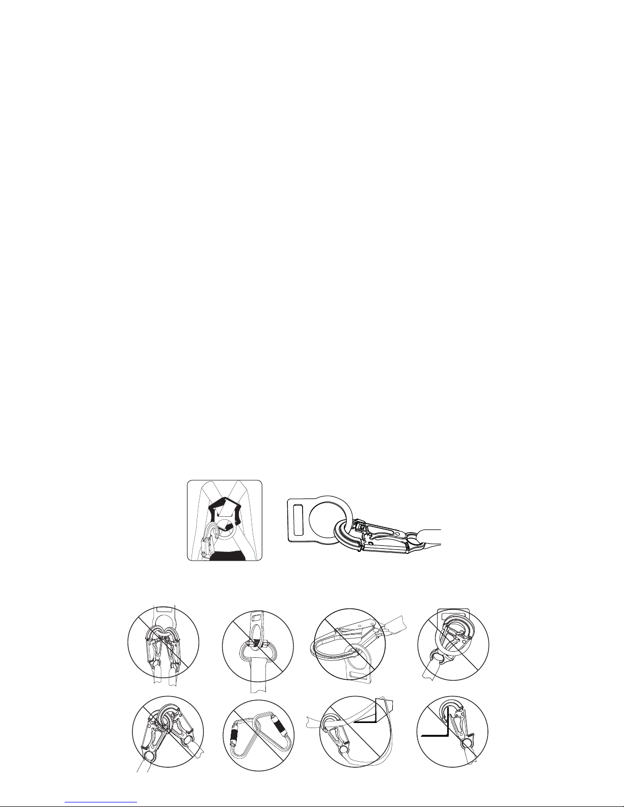
COMPATIBLE CONNECTIONS
INCOMPATIBLE CONNECTIONS
ANSI Z359.2 states that anchorages selected for fall arrest systems must have a strength capable of
sustaining static loads, applied in all permitted directions by the system:
A) no less than 5,000 pounds (22.2 kN) for non-certi ed anchorages; or
B) at least two times the maximum arresting force for certi ed anchorages;
C) according to ANSI Z359.6, Specifi cations and Design Requirements for Active Fall
Protection Systems.
When more than one personal fall arrest system is attached to the anchorage, the strength in (A) or
(B) must be multiplied by the number of personal fall arrest systems attached to the anchorage.
CONNECTION REQUIREMENTS
COMPATIBILITY LIMITATIONS
All connecting subsystems must only be coupled to compatible connectors. OSHA 29 CFR 1910.140
and 1926.502 prohibit snap hooks from being engaged to certain objects unless two requirements are
met: snap hook must be a locking type and must be “designed for” making such a connection. Under
OSHA “designed for” means that the manufacturer of the snap hook speci cally designed the snap
hook to be used to connect to the equipment in question.
The following connections must be avoided because they can result in rollout* when a non-locking
snap hook is used:
• Direct connection of a snap hook to horizontal lifeline.
• Two (or more) snap hooks connected to one D-ring.
• Two snap hooks connected to each other.
• A snap hook connected back on its integral lanyard.
• A snap hook connected to a webbing loop or webbing lanyard.
• Improper dimensions of the D-ring, rebar, or other connection point in relation to the snap
hook dimensions that would allow the snap hook keeper to be depressed by a turning motion
of the snap hook.
*Rollout: A process by which a snap hook or carabiner unintentionally disengages from another
connector or object to which it is coupled.
NO! NO! NO! NO!
NO!NO!NO!NO!
Page 5
5
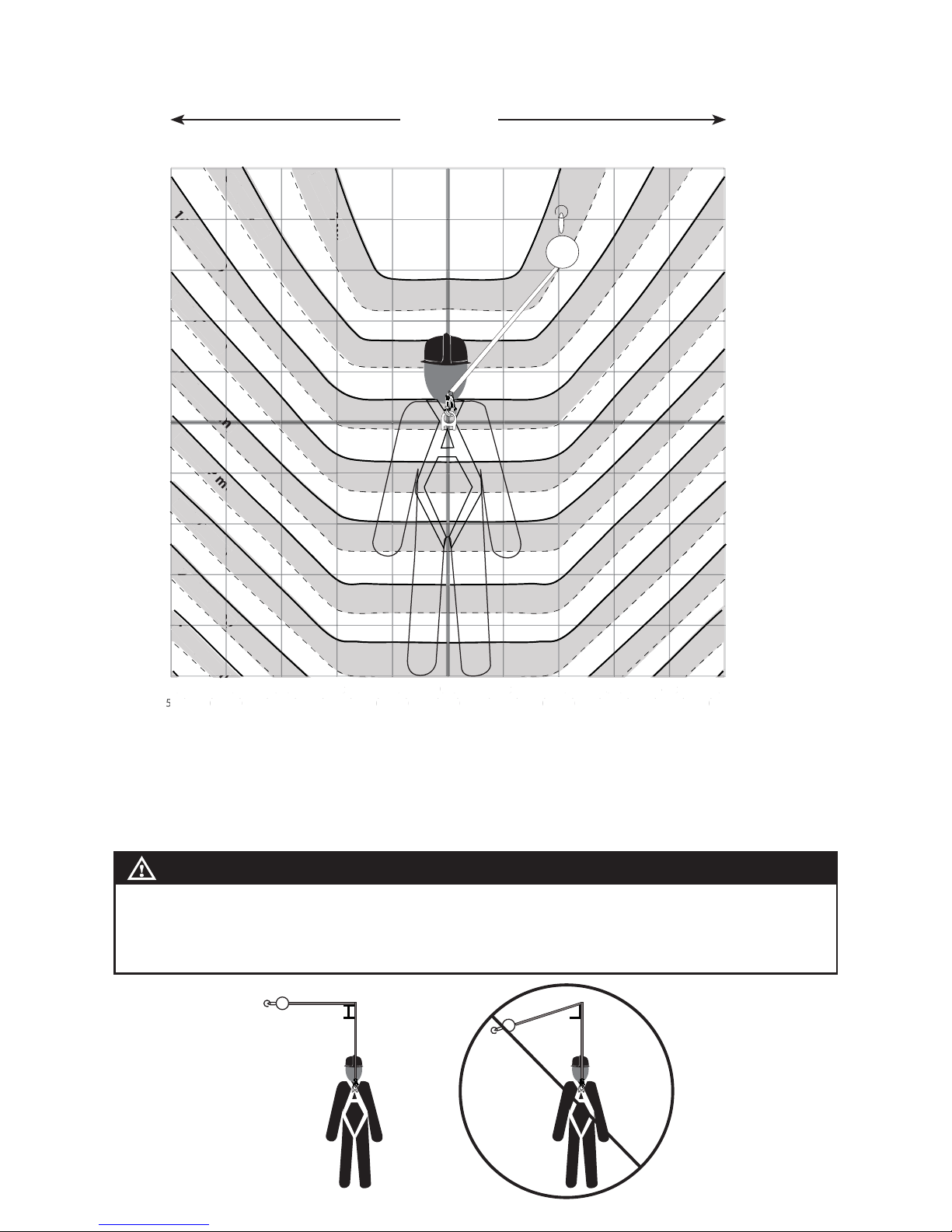
CLEARANCE REQUIREMENTS
C
LEARANCE REQUIREMENT WITH OFFSET AND SETBACK DISTANCE
FOR LEADING EDGE APPLICATIONS FOR R410020LE AND R410030LE
SETBACK
DISTANCE
OFFSET
DISTANCE
2 Foot
(0.6m)
4 Foot
(1.2m)
6 Foot
(1.8m)
8 Foot
(2.4m)
10 FOOT
(3.0m)
12 Foot
(3.7m)
14 Foot
(4.3m)
16 Foot
(4.9m)
18 Foot
(5.5m)
20 Foot+
(6.1m)+
0 Foot (0m)
17.0 ft
(5.2m)
17.0 ft
(5.2m)
17.0 ft
(5.2m)
17.0 ft
(5.2m)
17.0 ft
(5.2m)
17.0 ft
(5.2m)
17.0 ft
(5.2m)
17.0 ft
(5.2m)
17.0 ft
(5.2m)
17.0 ft
(5.2m)
2 Foot (0.6m)
17.8 ft
(5.4m)
17.5 ft
(5.3m)
17.3 ft
(5.3m)
17.2 ft
(5.2m)
17.2 ft
(5.2m)
17.2 ft
(5.2m)
17.1 ft
(5.2m)
17.1 ft
(5.2m)
17.1 ft
(5.2m)
17.1 ft
(5.2m)
4 Foot (1.2m)
19.5 ft
(5.9m)
18.7 ft
(5.7m)
18.2 ft
(5.5m)
17.9 ft
(5.5m)
17.8 ft
(5.4m)
17.6 ft
(5.4m)
17.6 ft
(5.4m)
17.5 ft
(5.3m)
17.4 ft
(5.3m)
17.4 ft
(5.3m)
6 Foot (1.8m)
20.2 ft
(6.2m)
19.5 ft
(5.9m)
19.0 ft
(5.8m)
18.7 ft
(5.7m)
18.4 ft
(5.6m)
18.2 ft
(5.5m)
18.1 ft
(5.5m)
18.0 ft
(5.5m)
17.9 ft
(5.5m)
8 Foot (2.4m)
21.0 ft
(6.4m)
20.3 ft
(6.2m)
19.8 ft
(6.0m)
19.4 ft
(5.9m)
19.1 ft
(5.8m)
18.9 ft
(5.8m)
18.7 ft
(5.7m)
18.5 ft
(5.6m)
10 Foot (3.0m)
20.6 ft
(6.3m)
20.2 ft
(6.2m)
19.9 ft
(6.1m)
19.9 ft
(6.0m)
19.4 ft
(5.9m)
DO NOT
USE
EXAMPLE: With the SRL-LE anchor set back 10 feet from the edge, the user can work up to 8 feet
(2.4m) offset along the leading edge. The required clearance is 19.8 feet (6.0 m) from the working
level to the nearest obstruction below.
The required clearance includes; Free Fall and Swing Fall Distance, Harness Stretch, Deceleration
Distance and Safety Factor.
CLEARANCE REQUIREMENT WITH OFFSET AND SETBACK DISTANCE
FOR LEADING EDGE APPLICATIONS FOR R410065LE
SETBACK
DISTANCE
OFFSET
DISTANCE
2 Foot
(0.6m)
4 Foot
(1.2m)
6 Foot
(1.8m)
8 Foot
(2.4m)
10 FOOT
(3.0m)
12 Foot
(3.7m)
14 Foot
(4.3m)
16 Foot
(4.9m)
18 Foot
(5.5m)
20 Foot+
(6.1m)+
0 Foot (0m)
17.5 ft
(5.4m)
17.5 ft
(5.4m)
17.5 ft
(5.4m)
17.5 ft
(5.4m)
17.5 ft
(5.4m)
17.5 ft
(5.4m)
17.5 ft
(5.4m)
17.5 ft
(5.4m)
17.5 ft
(5.4m)
17.5 ft
(5.4m)
2 Foot (0.6m)
18.3 ft
(5.6m)
18.0 ft
(5.5m)
17.8 ft
(5.5m)
17.7 ft
(5.4m)
17.7 ft
(5.4m)
17.7 ft
(5.4m)
17.6 ft
(5.4m)
17.6 ft
(5.4m)
17.6 ft
(5.4m)
17.6 ft
(5.4m)
4 Foot (1.2m)
20.0 ft
(6.1m)
19.2 ft
(5.9m)
18.7 ft
(5.7m)
18.4 ft
(5.6m)
18.3 ft
(5.6m)
18.1 ft
(5.5m)
18.1 ft
(5.5m)
18.0 ft
(5.5m)
17.9 ft
(5.5m)
17.9 ft
(5.5m)
6 Foot (1.8m)
20.7 ft
(6.3m)
20.0 ft
(6.1m)
19.5 ft
(5.9m)
19.2 ft
(5.9m)
18.9 ft
(5.8m)
18.7 ft
(5.7m)
18.6 ft
(5.7m)
18.5 ft
(5.6m)
18.4 ft
(5.6m)
8 Foot (2.4m)
21.5 ft
(6.6m)
20.8 ft
(6.3m)
20.3 ft
(6.2m)
19.9 ft
(6.1m)
19.6 ft
(6.0m)
19.4 ft
(5.9m)
19.2 ft
(5.9m)
19.0 ft
(5.8m)
10 Foot (3.0m)
21.1 ft
(6.4m)
20.7 ft
(6.3m)
20.4 ft
(6.2m)
20.1 ft
(6.1m)
19.9 ft
(6.1m)
DO NOT
USE
EXAMPLE: With the SRL-LE anchor set back 10 feet from the edge, the user can work up to 8 feet
(2.4m) offset along the leading edge. The required clearance is 20.3 feet (6.2 m) from the working
level to the nearest obstruction below.
The required clearance includes; Free Fall and Swing Fall Distance, Harness Stretch, Deceleration
Distance and Safety Factor.
Page 6
6
O
FFSET CLEARANCE REQUIREMENTS FOR R410020LE AND R410030LE
FOR NON LEADING EDGE APPLICATIONS
EXAMPLE: With the R410020LE or R410030LE anchored 4 feet above the users D-ring and the user
works 2 feet away (offset) from directly overhead (centerline), the required clearance is 6 feet (1.8 m)
from the working level to the nearest obstruction below.
The required clearance includes; Free Fall and Swing Fall Distance, Harness Stretch, Deceleration
Distance and Safety Factor.
D-ring
Height
Above
D-ring
Below
D-ring
1 ft
(0.3 m)
0 ft
(0 m)
1 ft
(0.3 m)
2 ft
(0.6 m)
3 ft
(0.9 m)
4 ft
(1.2 m)
5 ft
(1.5 m)
5 ft
(1.5 m)
4 ft
(1.2 m)
3 ft
(0.9 m)
2 ft
(0.6 m)
3 ft
(0.9 m)
2 ft
(0.6 m)
1 ft
(0.3 m)
0 ft
(0 m)
-1 ft
(-0.6 m)
-2 ft
(-0.6 m)
-3 ft
(-0.9 m)
-4 ft
(-1.2 m)
-5 ft
(-1.5 m)
4 ft
(1.2 m)
5 ft
(1.5 m)
1 ft
(0.3 m)
0 ft
(0 m)
1 ft
(0.3 m)
2 ft
(0.6 m)
3 ft
(0.9 m)
4 ft
(1.2 m)
5 ft
(1.5 m)
5 ft
(1.5 m)
4 ft
(1.2 m)
3 ft
(0.9 m)
2 ft
(0.6 m)
3 ft
(0.9 m)
2 ft
(0.6 m)
1 ft
(0.3 m)
0 ft
(0 m)
-1 ft
(-0.6 m)
-2 ft
(-0.6 m)
-3 ft
(-0.9 m)
-4 ft
(-1.2 m)
-5 ft
(-1.5 m)
4 ft
(1.2 m)
5 ft
(1.5 m)
6 ft (1.8 m)
8 ft (2.4 m)
10 ft (3.0 m)
12 ft (3.7 m)
14 ft (4.3 m)
16 ft (4.9 m)
5 ft
(1.5 m)
7 ft (2.1 m)
9 ft (2.7 m)
11 ft (3.4 m)
13 ft (4.0 m)
15 ft (4.6 m)
17 ft (5.2 m)
19 ft (5.8 m)
21 ft (6.4 m)
18 ft (5.5 m)
20 ft (6.1 m)
22 ft (6.7 m)
20 ft (6.1 m)
20
)
18 ft (5.5 m)
t (5
16 ft (4.9 m)
.9
14 ft (4.3 m
m)
m
(3
10 ft (3.0 m)
)
8 ft (2.4 m)
6 ft (1.8 m)
8
22 ft (6.7 m)
ft
0.3 m
)
ft
0 m
)
ft
0.3 m
)
2 ft
0.6 m
)
3 ft
0.9 m
)
4 ft
1.2 m
)
ft
m
)
5
f
1.5
4 f
t
1.2 m
)
ft
0.9 m
)
ft
0.6 m
)
Offset Offset
Centerline
WARNING!
The allowable angle of redirection of the lifeline portion of the SRL-LE at the edge over which
a fall might occur (measured between the two sides formed by the redirected lifeline) must be
at least 90 degrees. The anchor point may only be situated at the same height as the edge at
which a fall might occur or above the edge.
NO!
≥90° <90°
Page 7
7
O
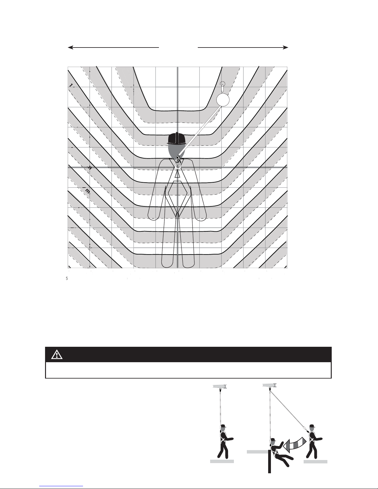
FFSET CLEARANCE REQUIREMENTS FOR R410065LE
FOR NON LEADING EDGE APPLICATIONS
1 ft
(0.3 m)
0 ft
(0 m)
1 ft
(0.3 m)
2 ft
(0.6 m)
3 ft
(0.9 m)
4 ft
(1.2 m)
5 ft
(1.5 m)
5 ft
(1.5 m)
4 ft
(1.2 m)
3 ft
(0.9 m)
2 ft
(0.6 m)
3 ft
(0.9 m)
2 ft
(0.6 m)
1 ft
(0.3 m)
0 ft
(0 m)
-1 ft
(-0.6 m)
-2 ft
(-0.6 m)
-3 ft
(-0.9 m)
-4 ft
(-1.2 m)
-5 ft
(-1.5 m)
4 ft
(1.2 m)
5 ft
(1.5 m)
1 ft
(0.3 m)
0 ft
(0 m)
1 ft
(0.3 m)
2 ft
(0.6 m)
3 ft
(0.9 m)
4 ft
(1.2 m)
5 ft
(1.5 m)
5 ft
(1.5 m)
4 ft
(1.2 m)
3 ft
(0.9 m)
2 ft
(0.6 m)
3 ft
(0.9 m)
2 ft
(0.6 m)
1 ft
(0.3 m)
0 ft
(0 m)
-1 ft
(-0.6 m)
-2 ft
(-0.6 m)
-3 ft
(-0.9 m)
-4 ft
(-1.2 m)
-5 ft
(-1.5 m)
4 ft
(1.2 m)
5 ft
(1.5 m)
7 ft (2.1 m)
9 ft (2.7 m)
11 ft (3.4 m)
13 ft (4.0 m)
15 ft (4.6 m)
17 ft (5.2 m)
6 ft
(1.8 m)
8 ft (2.4 m)
10 ft (3.0 m)
12 ft (3.7 m)
14 ft (4.3 m)
16 ft (4.9 m)
18 ft (5.5 m)
20 ft (6.1 m)
22 ft (6.7 m)
19 ft (5.8 m)
21 ft (6.4 m)
23 ft (7.0 m)
21 ft (6.4 m)
21
)
19 ft (5.8 m)
17 ft (5.2 m)
.2
15 ft (4.6 m
m)
m
(4
11 ft (3.4 m)
)
9 ft (2.7 m)
7 ft (2.1 m)
1
)
)
)
ft
0.3 m
)
ft
0 m
)
1 ft
0.3 m
)
2 ft
0.6 m
)
ft
0.9 m
)
4
ft
1.2 m
)
ft
m
)
f
1.5
4 ft
1.2 m
)
ft
0.9 m
)
2 ft
0.6 m
)
)
D-ring
Height
Above
D-ring
Below
D-ring
Offset Offset
Centerline
E
XAMPLE: With the R410065LE anchored 4 feet above the users D-ring and the user works 2 feet away
(offset) from directly overhead (centerline), the required clearance is 7 feet (2.1 m) from the working
level to the nearest obstruction below.
The required clearance includes; Free Fall and Swing Fall Distance, Harness Stretch, Deceleration
Distance and Safety Factor.
SWING FALL
HAZARD
Anchorages
Correct Incorrect
SWING FALLS
To minimize the possibility of a swing fall, anchor as
directly above the work area as possible. Striking
objects horizontally, due to the pendulum effect, may
cause serious injury. Swing falls also increase the
vertical fall distance of a worker, compared to a fall
directly below the anchorage connector. Swing falls may
be reduced by using overhead anchorage connectors
that move with the worker.
WARNING!
Striking objects horizontally due to the pendulum effect of a swing fall may cause serious
injury or death.
Page 8
8
HORIZONTAL SYSTEMS
Applications where the SRL-LE is used horizontally or with a horizontal system, the SRL-LE and
horizontal system components must be compatible. Both the horizontal and vertical distances are
required for clearance calculations. Horizontal systems must be designed and installed under the
supervision of a quali ed person.
These units are suitable for use with horizontal lifelines.
PERFORMANCE
The Werner Co. SRL-LE was successfully tested for horizontal use and falls over a steel edge without
burrs, concrete and b-decking and as a result, these devises may be used in applications where a fall
may occur over similar edges.
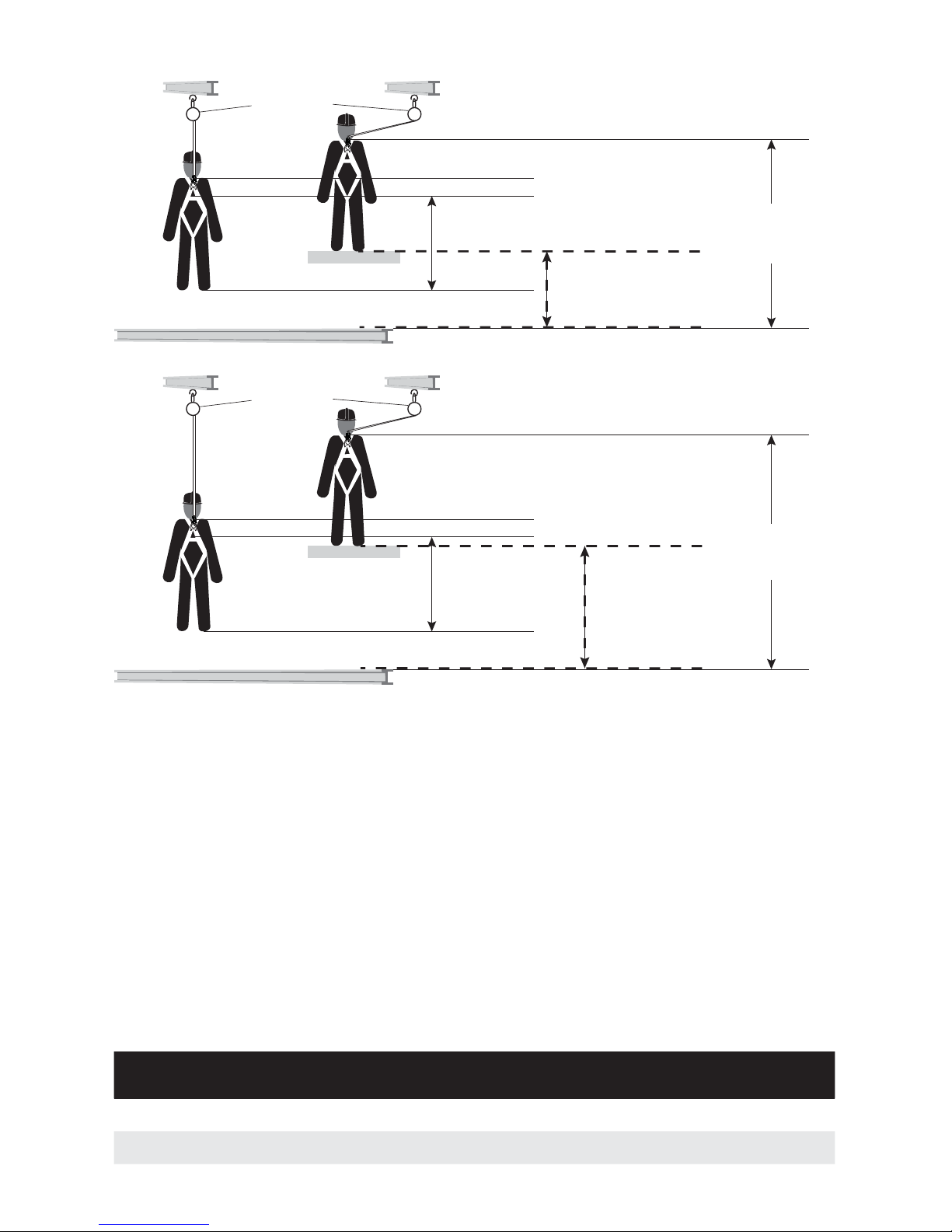
LEADING EDGE USE APPLICATIONS FOR R410020LE AND R410030LE
Working Level
Lower Level or Obstruction
Self Retracting
Lifeline
Maximum Arrest Distance
(per ANSI Z359.14 Class A)
2 ft. (0.6 m)
Safety Factor
2 ft. (0.6 m)
1 ft. (0.31 m) Harness Stretch
To Worker’s Back D-Ring
5 ft. (1.5 m)
Total Estimated
Distance
10 ft . (3.0 m)
Estimated Clearance
Required
5 ft .
(1.5 m)
Working Level
Lower Level or Obstruction
Self Retracting
Lifeline
Maximum Arrest Distance
(per ANSI Z359.14 Class B)
4.5 ft. (1.4 m)
Safety Factor
2 ft. (0.6 m)
1 ft. (0.31 m) Harness Stretch
To Worker’s Back D-Ring
5 ft. (1.5 m)
Total Estimated
Distance
12.5 ft .
(3.81 m)
Estimated Clearance
Required
7.5 ft .
(2.13 m)
CLEARANCE CALCULATIONS
Standards and
Regulations
Free Fall
Limit
Maximum
Arrest Force
Average
Arrest Force
Minimum
Setback Distance
Clearance
Requirement When
Falling Over Edge
Capacity
ANSI Z359.14
SRD-LE
6 ft
(1.8 m)
1800 lbs
(8 kN)
900 lbs
(4 kN)
2 ft
(0.6 m)
17 ft
(5.1 m)
130 - 310 lbs
(59 - 141 kg)
OSHA 29 CFR
1910.140/1926.502
6 ft
(1.8 m)
1800 lbs
(8 kN)
N/A
2 ft
(0.6 m)
17 ft
(5.1 m)
310 lbs
(141 kg)
Page 9

9
L
EADING EDGE USE APPLICATIONS FOR R410065LE
O
VERHEAD USE NON LEADING EDGE APPLICATIONS FOR R410020LE AND R410030LE
OVERHEAD USE NON LEADING EDGE APPLICATIONS FOR R410065LE
OPERATION
BEFORE EACH USE
The user must read and understand these user instructions, as well as the user instructions for every
component and subsystem of the personal fall arrest system.
Users must have a rescue plan, and the means to implement it, that provides for the prompt rescue of
employees in the event of a fall or assures that employees are able to rescue themselves.
Check the operation by pulling smoothly on the lifeline, then pulling sharply on the lifeline to engage
the locking mechanism.
SRL-LE’s must be inspected prior to each use. See INSPECTION.
CONNECTION
Attach the housing connector of the SRL-LE to the anchorage or anchorage connector. The opposing
end is connected to the dorsal D-ring of the full body harness.
WARNING!
Before using a personal fall arrest system, employees must be trained in accordance with
the requirements of OSHA 29 CFR 1910.30 and 1926.503 and/or applicable local, state,
governmental and jurisdictional agencies, in the safe use of the system and its components.
Personal fall arrest systems, including SRL-LE’s, must be inspected prior to each use for wear,
damage, and other deterioration. Defective components must be immediately removed from
service in accordance with the requirements of OSHA 29 CFR 1910.140 and 1926.502 and/or
applicable local governmental and jurisdictional standards.
Standards and
Regulations
Free Fall
Limit
Maximum
Arrest Force
Average
Arrest Force
Minimum
Setback Distance
Clearance
Requirement When
Falling Over Edge
Capacity
ANSI Z359.14
SRD-LE
6 ft
(1.8 m)
1800 lbs
(8 kN)
900 lbs
(4 kN)
2 ft
(0.6 m)
17.5 ft
(5.4 m)
130 - 310 lbs
(59 - 141 kg)
OSHA 29 CFR
1910.140/1926.502
6 ft
(1.8 m)
1800 lbs
(8 kN)
N/A
2 ft
(0.6 m)
17.5 ft
(5.4 m)
310 lbs
(141 kg)
Standards and
Regulations
Maximum Arrest
Distance
Free Fall Limit
Maximum Arrest
Force
Average Arrest
Force
Capacity
ANSI Z359.14
SRD Class A
24 in
(610 mm)
2 ft
(0.6 m)
1800 lbs
(8 kN)
1,350 lbs
(6 kN)
130 - 310 lbs
(59 - 141 kg)
OSHA 29 CFR
1910.140/1926.502
42 in
(1067 mm)
2 ft
(0.6 m)
1800 lbs
(8 kN)
N/A
400 lbs
(181 kg)
Standards and
Regulations
Maximum Arrest
Distance
Free Fall Limit
Maximum Arrest
Force
Average Arrest
Force
Capacity
ANSI Z359.14
SRD Class B
32 in
(812 mm)
2 ft
(0.6 m)
1800 lbs
(8 kN)
900 lbs
(4 kN)
130 - 310 lbs
(59 - 141 kg)
OSHA 29 CFR
1910.140/1926.502
42 in
(1067 mm)
2 ft
(0.6 m)
1800 lbs
(8 kN)
N/A
400 lbs
(181 kg)
WARNING!
Never attach an additional energy absorbing lanyard, self retracting lifeline, or similar
component to lengthen the lifeline.
Page 10

10
INSPECTION
FREQUENCY
All components of SRL-LE’s must be inspected prior to each use, and annually by an OSHA de ned
“competent person” other than the user. Local, state, governmental and jurisdictional agencies
governing occupational safety may require the user to conduct more frequent or mandatory
inspections.
CRITERIA
All components of the SRL-LE must be inspected.
All markings must be legible and attached to the product.
Housing must be free from cracks, distortion or any other damage.
White web visible outside the shock pack is the fall indicator that the SRL-LE has been subjected to
the forces of arresting a fall.
Reserve cable is wrapped in colored tape. Remove from service if colored tape has exited the unit.
Check the operation of the unit by pulling smoothly on the lifeline, then pulling sharply on the lifeline to
engage the locking mechanism. Unit must not slip when locked.
Cable must be inspected for kinks, broken strands, corrosion, abrasion, or other signs of wear and/or
damage. Swaged terminations must be secure with the thimble tight and no visible damage.
All equipment must be free of corrosion, chemical attack, alteration, excessive heating or wear.
All snap hooks and carabiners on product must be able to self-close and lock. All hardware must be
free of cracks, sharp edges, deformation, corrosion, or any evidence of defect.
All components of the fall arrest system must be inspected. See User Instructions supplied with each
product.
CLEANING, MAINTENANCE AND STORAGE
CLEANING
Cleaning and maintenance may be performed by the user. The SRL-LE may be wiped down with a
mild detergent and clean water solution, and rinsed with a dampened clean cloth to remove detergent.
The hardware can also be wiped down to remove grease or dirt with a clean dry cloth.
WARNING!
Only Werner Co., or persons or entities authorized in writing by Werner Co., shall make repairs
or alterations to the equipment.
Type Of Use Application Examples Conditions Of Use Inspection Frequency
Competent Person
Infrequent to
Light
Rescue and con ned space,
factory maintenance
Good storage conditions,
indoor or infrequent outdoor
use, room temperature, clean
environments
Annually
Moderate to
Heavy
Transportation, residential
construction, utilities,
warehouse
Fair storage conditions, indoor
and extended outdoor use, all
temperatures, clean or dusty
environments
Semi-annually to
annually
Severe to
Continuous
Commercial construction, oil
and gas, mining
Harsh storage conditions,
prolonged or continuous
outdoor use, all temperatures,
dirty environments
Quarterly to semiannually
Page 11
11
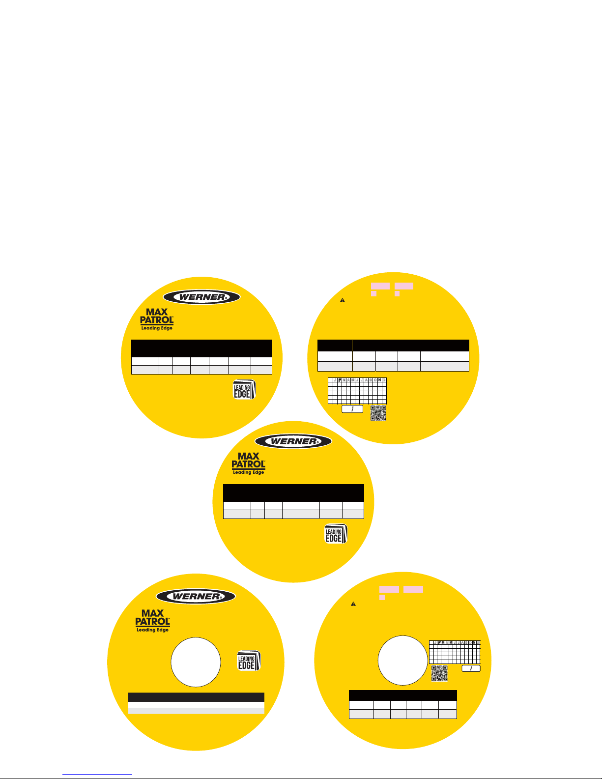
LABELS
M
AINTENANCE
SRL-LE’s requiring maintenance must be tagged “unusable” and removed from service. Do not use
any SRL-LE that requires maintenance. Cleaning and maintenance may be performed by the user.
Snap hooks may require periodic lubrication. Do not apply oil, grease, or other contaminants on the
webbing or cable. Use a dry lubricant that has proper resistance to temperature extremes, moisture,
and corrosion. Do not over-lubricate.
STORAGE
SRL-LE’s should be stored in a cool, dry place out of direct sunlight when not in use. Do not store
where damage from environmental factors such as heat, light, excessive moisture, oil, chemicals and
their vapors, or other degrading elements may be present.
Do not store damaged equipment or equipment in need of maintenance in the same area as product
approved for use.
Equipment that has been stored for an extended period must be inspected as de ned in these User
Instructions prior to use.
be trained in the safe use of the system, required by OSHA 29 CFR 1910.30 and 1926.503, or local safety
Never connect to carrying handle. Suitable for horizontal use and with horizontal lifelines.
www.wernerco.com
Overhead Use Non Leading Edge Applicaons
SPECIFICATIONS:
Lifeline: Galvanized Steel Cable, 3/16”
Load Indicator Inspection:
White web visible outside shock pack is the
fall indicator, and the SRL has been subjected
to the forces of arresting a fall.
© 2018 Werner Co.
P/N 116401-03
Rev. A 02/18
20ft (6m)
Serial # Mfg. Date
30ft (9.1m)
Length:
*See user instrucons for non-leading edge non-overhead use.
Standards and
Regulaons
Max Arrest
Distance
Free Fall
Limit
Max Arrest
Force
Average
Arrest Force
Capacity
ANSI Z359.14
SRD Class A
24 in
(610 mm)
2
(0.6 m)
1800 lbs
(8 kN)
1,350 lbs
(6 kN)
130 - 310 lbs
(59 - 141 kg)
OSHA 29 CFR
1910.140/1926.502
42 in
(1067 mm)
2
(0.6 m)
1800 lbs
(8 kN)
N/A
400 lbs
(181 kg)
WAR NIN G:
Made in Taiwan
Date of first use
J
F M A M J J A S O N D
1
2
3
4
5
Compliant fall protecon equipment must only be used as it was designed. Users MUST read
and follow all user instrucons provided with the product. Before using a fall arrest system, users must
regulaons. Product must be inspected prior to each use according to the user instrucons. See user instrucons
for inspecon frequency. Before each use check the device for locking by pulling sharply to engage the locking
mechanism. Only make compable connecons. Connect only using swivel eye.
User repairs and alteraons are NOT permied. Avoid physical and environmental hazards such as thermal, machinery,
and electrical and chemical sources. For proper use see supervisor, user instrucons, or contact Werner Co.
Tested and approved for
leading edge use over steel beam,
B-Deck and precast concrete.
Model: R410020LE
Self Retracting Lifeline
with Leading Edge Capability
© 2018 Werner Co.
P/N 116401-01
Rev. A 02/18
Made in Taiwan
Leading Edge Use Applicaons
* See user instructions for offset clearances.
Standards and
Regulaons
Free Fall
Limit
Max Arrest
Force
Average
Arrest Force
Min Setback
Distance
*Clearance
Requirement
when Falling
over Edge
Capacity
ANSI Z359.14
SRD-LE
6
(1.8 m)
1800 lbs
(8 kN)
900 lbs
(4 kN)
2
(0.6 m)
17
(5.1 m )
130 - 310 lbs
(59 - 141 kg)
OSHA 29 CFR
1910.140/1926.502
6
(1.8 m)
1800 lbs
(8 kN)
N/A
2
(0.6 m)
17
(5.1 m )
310 lbs
(141 kg)
Tested and approved for
leading edge use over steel beam,
B-Deck and precast concrete.
Model: R410030LE
Self Retracting Lifeline
with Leading Edge Capability
Made in Taiwan
Leading Edge Use Applicaons
* See user instructions for offset clearances.
Standards and
Regulaons
Free Fall
Limit
Max Arrest
Force
Average
Arrest Force
Min Setback
Distance
*Clearance
Requirement
when Falling
over Edge
Capacity
ANSI Z359.14
SRD-LE
6
(1.8 m)
1800 lbs
(8 kN)
900 lbs
(4 kN)
2
(0.6 m)
17
(5.1 m )
130 - 310 lbs
(59 - 141 kg)
OSHA 29 CFR
1910.140/1926.502
6
(1.8 m)
1800 lbs
(8 kN)
N/A
2
(0.6 m)
17
(5.1 m )
310 lbs
(141 kg)
© 2018 Werner Co.
P/N 116401-02
Rev. A 02/18
* See user instructions for offset clearances.
www.wernerco.com
SPECIFICATIONS:
Lifeline: Galvanized Steel Cable, 3/16”
Load Indicator Inspection:
White web visible outside
shock pack is the fall indicator,
and the SRL has been subjected
to the forces of arresting a fall.
65 ft (19.8m)
Serial # Mfg. Date
Length:
Overhead Use Non Leading Edge Applicaons
*See user instrucons for non-leading edge non-overhead use.
Standards and
Regulaons
Max Arrest
Distance
Free Fall
Limit
Max Arrest
Force
Average
Arrest Force
Capacity
ANSI Z359.14
SRD Class B
32 in
(812 mm)
2
(0.6 m)
1800 lbs
(8 kN)
900 lbs
(4 kN)
130 - 310 lbs
(59 - 141 kg)
OSHA 29 CFR
1910.140/1926.502
42 in
(1067 mm)
2
(0.6 m)
1800 lbs
(8 kN)
N/A
400 lbs
(181 kg)
WAR NIN G:
be trained in the safe use of the system, required by OSHA 29 CFR 1910.30 and 1926.503, or local safety
Never connect to carrying handle. Suitable for horizontal use and with horizontal lifelines.
Compliant fall protecon equipment must only be used as it was designed. Users MUST read
and follow all user instrucons provided with the product. Before using a fall arrest system, users must
regulaons. Product must be inspected prior to each use according to the user instrucons. See user
instrucons for inspecon frequency. Before each use check the device for locking by pulling sharply to engage
the locking mechanism. Only make compable connecons. Connect only using swivel eye.
User repairs and alteraons are NOT permied. Avoid physical and environmental hazards such as thermal, machinery,
and electrical and chemical sources.
For proper use see supervisor,
user instrucons,
or contact Werner Co.
Tested and approved
for leading edge
use over steel beam,
B-Deck and
precast concrete.
Model: R410065LE
Self Retracting Lifeline
with Leading Edge Capability
Made in Taiwan
© 2018 Werner Co.
P/N 116402-01
Rev. A 02/18
Leading Edge Use Applicaons
1
2
3
4
5
J
F M A M J J A S O N D
Date of first use
Made in Taiwan
© 2018 Werner Co.
P/N 116402-02
Rev. A 02/18
Standards and
Regulations
Free Fall
Limit
Maximum
Arrest Force
Average
Arrest Force
Minimum
Setback Distance
Clearance
Requirement When
Falling Over Edge
Capacity
ANSI Z359.14
SRD-LE
6 ft
(1.8 m)
1800 lbs
(8 kN)
900 lbs
(4 kN)
2 ft
(0.6 m)
17.5 ft
(5.4 m)
130 - 310 lbs
(59 - 141 kg)
OSHA 29 CFR
1910.140/1926.502
6 ft
(1.8 m)
1800 lbs
(8 kN)
N/A
2 ft
(0.6 m)
17.5 ft
(5.4 m)
310 lbs
(141 kg)
Page 12

PN115849-01 ©2018 Werner Co. Rev B 6/18
Werner Co. Fall Protection
93 Werner Rd. Greenville, PA 16125
724-588-2000 • 888-523-3371 toll free • 888-456-8458 fax
 Loading...