

Page 1
FALL PROTECTION
PROTECCIÓN CONTRA CAÍDAS
USER INSTRUCTIONS
INSTRUCCIONES PARA EL USUARIO
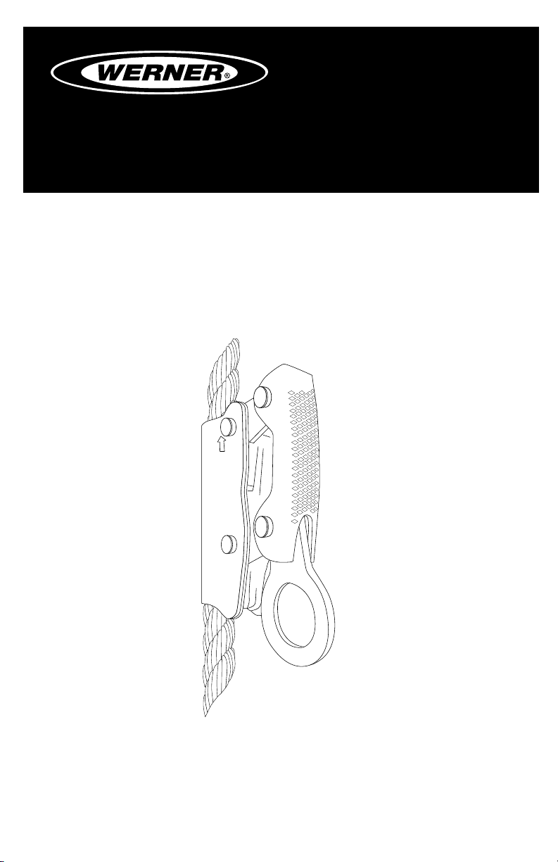
MANUAL ROPE ADJUSTER
Complies with ANSI Z359.1-2007,
OSHA 1910 and 1926 requirements.
AJUSTADOR MANUAL PARA CUERDA
TRENZADA
Cumple con las normas ANSI Z359.1-2007,
OSHA 1910 y 1926.
(This manual applies to manual rope grabs L210100 and L210101.)
(Este manual aplica a ajustador manual para cuerda trenzada
L210100 y L210101.)
Werner Fall Protection 724-588-2000
93 Werner Rd. 888-523-3371 toll free/ llamada gratuita
Greenville, PA 16125 888-456-8458 fax
Page 2
CAUTION!
If use of fall protection equipment is necessary then the work
environment is dangerous and potentially deadly. Werner Company
products are designed to eliminate as much of the hazard as possible
but can do that ONLY if they are used correctly. Use this equipment as
it was designed to be used, after appropriate training, under the direct
supervision of a competent person, according to the instructions
provided, and in accordance with OSHA and local safety regulations.
User MUST read and understand all cautions and instructions. Failure
to heed these guidelines could result in injury or even death. Please,
WORK SAFE! WORK SMART!
ENGLISH
Page 2
Page 3

MANUAL ROPE ADJUSTER
USER INSTRUCTIONS
Contents
I. BEFORE USING THE ROPE GRAB .................................................................. 4
a. Inspect ......................................................................................................................4
b. Compatibility ............................................................................................................6
c. Fall Protection Plan ..................................................................................................6
d. Training .....................................................................................................................9
II. ANCHOR INSTALLATION AND USE ...............................................................9
a. Making a Connection .............................................................................................10
b. Anchorage Strength ..............................................................................................11
c. Lifelines ..................................................................................................................12
d. Lanyards .................................................................................................................13
e. Body Support .........................................................................................................13
f. Attaching Rope Grab to the Lifeline .....................................................................13
g. Positioning Rope Grab on the Lifeline .................................................................14
h. Connecting to Anchorage Connector or Anchorage Connector .......................14
i. Connecting to the Body Support ...........................................................................15
j. Connecting to the Rope Grab ................................................................................15
k. Use of LifeLines .....................................................................................................15
l. After Use ..................................................................................................................16
III. USE WARNINGS, RESTRICTIONS AND CAUTIONS ................................... 16
a. Purpose ..................................................................................................................16
b. Rated Capacity .......................................................................................................17
c. Limitations ..............................................................................................................17
d. Governing Requirements ......................................................................................18
IV. LABELS/IDENTIFICATION/INSPECTION RECORDS .................................. 18
V. EQUIPMENT RECORDS ................................................................................20
VI. INSPECTION RECORDS ..............................................................................20
ENGLISH
Page 3
Page 4
Warning:
This product is just one part of a personal fall arrest system. It must
be matched correctly with other components to form a complete and
functional system. The user must understand the function of each of
these components and follow the manufacturer’s instructions for use
for each. The user must be provided these instructions, should read
and follow them, and consult the competent person who will supervise
his work if he has any questions about any part of the instructions.
The employer must provide training in the proper use, inspection, and
maintenance of all components in the system, and these instructions
can be used as part of that training. The equipment should be used
ONLY in accordance with these instructions, local ordinances and
codes, the applicable OSHA and ANSI standards, and the employer’s
safety plan.
Alterations or misuse of this product or failure to follow instructions
may result in serious injury or death.
IF YOU HAVE ANY QUESTIONS ABOUT ANYTHING IN THESE
INSTRUCTIONS, THE EQUIPMENT, OR PROPER USE OF THE
EQUIPMENT, CONTACT WERNER CO. FOR MORE INFORMATION.
I. Before Using the Rope Adjuster
Before using this equipment the user should take certain steps to
ensure that it is in suitable condition and safe for use. Users must
read and understand these instructions. It is the employer’s obligation
to ensure that all users have been trained in safe work procedures as
well as in the use and limitations of fall protection equipment. All users
should be aware of and comply with all applicable OSHA, ANSI, CSA
and local or regional regulations concerning fall protection equipment
and its use.
a. Inspect
Examine all equipment thoroughly, daily before use by the user,
and periodically by a competent person who is not the user.
1. Before installation of this equipment, carefully inspect it to assure
it is in serviceable condition.
ENGLISH
2. The manual rope adjuster (manual rope grab) must be inspected
by a competent person other than the user at least annually.
Page 4
Page 5

MANUAL ROPE ADJUSTER
USER INSTRUCTIONS
Record the results of each formal inspection in the inspection
log.
3. Inspect the action of the lanyard connection handle for freedom
of motion. There should be no binding or sticking. The lanyard
connection handle is spring loaded and when raised the internal
cams should release from the lifeline allowing the rope grab to be
re-positioned. Releasing the spring loaded lanyard connection
handle should result in the internal cams binding onto the lifeline
preventing movement.
4. Inspect the rope channel for signs of rope wear. There should be
no dips or depressions worn into the rope channel. The internal
cams which come in contact with the lifeline should have a
visible serrated face.
5. Inspect each system component or subsystem per associated
manufacturer’s instructions.
6. Record the inspection date and results in the inspection log
7. INSPECTION STEPS FOR LIFELINE: (See the Lifeline User
Instruction Manual for complete details)
i. Lifeline hardware must not be damaged, broken, distorted,
or have any sharp edges, burrs, cracks, worn parts, or
corrosion. Ensure the connecting hooks work properly. Hook
gates must move freely and lock upon closing.
ii. Inspect the rope for concentrated wear. The material must be
free of frayed strands, broken yarns, cuts, abrasions, burns,
and discoloration. The rope must be free of knots, excessive
soiling, heavy paint buildup, and rust staining. Rope splices
must be tight, with ve full tucks, and thimbles must be
held by the splice. Cracked or distorted rope thimbles may
indicate that the lifeline has been impact loaded. Check for
chemical or heat damage (indicated by brown, discolored,
or brittle areas). Check for ultraviolet damage, indicated
by discoloration and the presence of splinters and slivers
on the rope surface. All of the above factors are known to
reduce rope strength. Damaged or questionable ropes must
be replaced.
iii. Inspect labels. All labels must be present and fully legible.
Replace labels if illegible or missing.
iv. Record the inspection date and results in the inspection log
found in the Lifeline User Instruction Manual.
Page 5
ENGLISH
Page 6

8. Verify that all labels are intact, in place, and legible.
9. If inspection reveals a defective condition or abnormalities in
any of these areas, remove unit from service immediately. A
competent person should be consulted to determine if that item
is safe for continued use or if it should be destroyed.
IMPORTANT: If this equipment has been subjected to forces
resulting from the arrest of a fall, it must be immediately
removed from service.
IMPORTANT: Do not attempt to alter, repair, or make substitutions
to the rope grab or rope grab parts. Equipment found to be
in defective condition must be removed from service. Repairs
may only be performed by Werner Co. or those authorized in
writing to do so.
b. Compatibility
Werner Co. equipment is designed for use with Werner Co. approved
components and subsystems only. Substitutions or replacements
made with non-approved components or subsystems may
jeopardize compatibility of equipment and may affect the safety and
reliability of the complete system.
Connectors are considered to be compatible with connecting
elements when they have been designed to work together in
such a way that their sizes and shapes do not cause their gate
mechanisms to inadvertently open regardless of how they become
oriented. Contact Werner Co. if you have any questions about
compatibility. Connectors (hooks, carabiners, and D-rings) must be
capable of supporting at least 5,000 lbs. (22.2kN). Connectors must
be compatible with the anchorage or other system components.
Do not use equipment that is not compatible. Non-compatible
connectors may unintentionally disengage. Connectors must be
compatible in size, shape, and strength. Self locking snap hooks
and carabiners are required by ANSI Z359 and OSHA.
ENGLISH
Page 6
c. Fall Protection Plan
Plan your fall arrest or restraint system before starting your work.
Take into consideration all factors affecting your safety at any
time during use. The following list gives some important points to
consider when planning your system:
Page 7
MANUAL ROPE ADJUSTER
USER INSTRUCTIONS
1. ANCHORAGE: Select a rigid anchorage point that is capable of
supporting the required loads. See section II.b.
The anchorage location must be carefully selected to reduce
possible free fall and swing fall hazards and to avoid striking an
object during a fall. For restraint systems the anchorage must be
located such that no vertical free fall is possible. For fall arrest
systems OSHA requires the anchorage be independent of the
means suspending or supporting the user.
2. FREE FALL: Do not work above the anchorage level, increased
fall distance will result. Personal fall arrest systems must be
rigged such that the potential free fall is never greater than six
feet. Restraint systems must be rigged such that there is no
possible vertical free fall.
3. FALL ARREST FORCES: The assembled fall arrest system
must keep fall arrest forces below 1,800 lbs. when used with a
full body harness. Do not use a body belt for fall arrest.
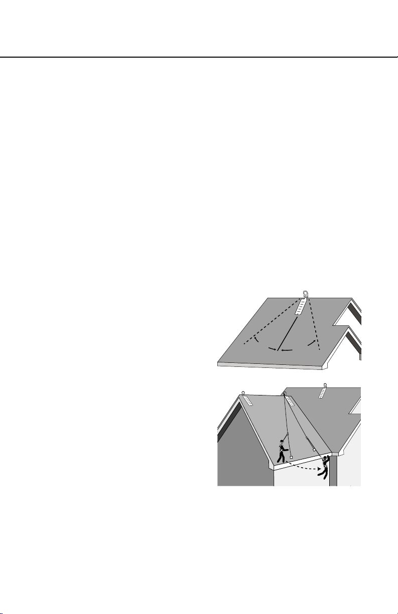
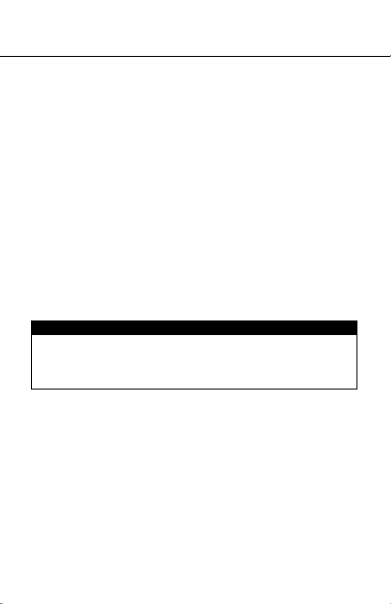
4. SWING FALLS: Swing falls
occur when the anchor is
not directly above the point
where a fall occurs. The
force of striking an object
while swinging can be great
and cause serious injury.
Minimize swing falls by
working as directly below the
anchorage as possible (the
worker must be positioned
within 30 degrees of the
roof anchor). It is acceptable
to captivate a lifeline (i.e.
rope grab system) to an
anchorage close to the work
area with a carabiner. Do
not captivate the lifeline of a
self retracting lifeline as this may affect the performance of its
internal braking.
30°
Working Range
Roof Anchor
30°
5. FALL CLEARANCE: Make certain enough clearance exists
in your fall path to prevent striking an object. The amount of
clearance needed is dependent upon the type of connecting
subsystem used and anchorage location.
Page 7
ENGLISH
Page 8
6. SHARP EDGES: Avoid working where parts of the system will
be in contact with, or abrade against, unprotected sharp edges.
7. RESCUE: Should a fall occur, the user (employer) must have a
rescue plan. If a worker falls and is forced to remain suspended
for any length of time, physical damage to the body or even
death can result. For this reason Werner, OSHA, ANSI, CSA
and most local regulations require that a rescue plan and the
means to implement the rescue plan are in place before use of
this equipment.
8. AFTER A FALL: Any equipment which has been subjected
to the force of arresting a fall must be removed from service
immediately.
9. GENERAL USE CONSIDERATIONS: Avoid working where
lifeline may cross or tangle with that of another worker. Do not
allow the lanyard to pass under arms or between legs. Do not
clamp, tie, or otherwise prevent the rope grab lanyard connection
handle from moving freely into the “locked” position.
10. SLOPED ROOFS: Provisions must be made (warning lines,
monitors, guardrails) to prevent swing falls from unprotected roof
edges or corners. The rope grab should be connected to the
body support using a locking carabiner (direct connection) or
a short lanyard. If a lanyard is used for connecting to the rope
grab, keep the length as short as possible, and never greater
than three feet. The lifeline must be protected from contact with
sharp or abrasive edges and surfaces. The rope grab locking
operation must not be hindered by interference with the roof or
objects on the roof surface.
11. UNSTABLE SURFACES: The rope grab is not suitable for use
on unstable or slowly shifting materials, such as sand or grain.
Warning:
Never connect more than one personal fall arrest or restraint system
to a single lifeline or rope grab.
Warning:
Follow manufacturer’s instructions for associated equipment used in
your fall protection or restraint system.
d. Training
ENGLISH
OSHA, ANSI, and most local ordinances require that workers using
this product receive adequate training before use of this product.
Page 8
Page 9
MANUAL ROPE ADJUSTER
USER INSTRUCTIONS
These instructions and their entire contents should be a part of that
training.
II. Rope Adjuster Installation and Use
Warning:
Do not alter or intentionally misuse this equipment. Consult with
Werner Co. if using this equipment with components or subsystems
other than those described in this manual. Some subsystem and
component combinations may interfere with the operation of this
equipment. Use caution when using this equipment around moving
machinery, electrical hazards, chemical hazards, and sharp edges.
Warning:
Do not use this system if you are unable to tolerate the impact of
a fall arrest. Age and tness can seriously affect your ability to
withstand a fall. Pregnant women and minors must not use this
equipment.
a. Making Connections
1. Only use self-locking snap hooks and carabiners with this
equipment. Only use connectors that are suitable to each
application. Ensure all connections are compatible in size, shape
and strength. Do not use equipment that is not compatible.
Ensure all connectors are fully closed and locked.
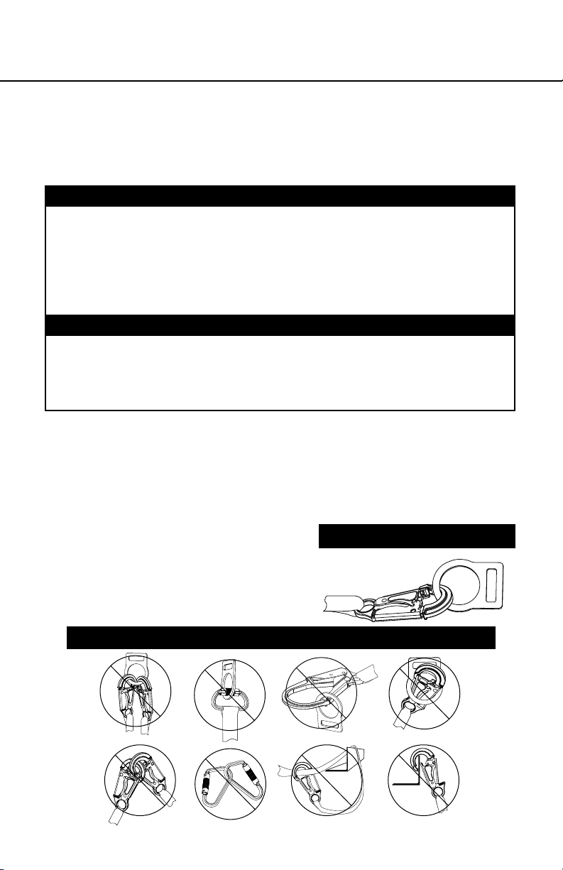
2. Werner Co. connectors (snap
hooks and carabiners) are
designed to be used only as
specied in each product’s
user’s instructions. See
inappropriate connections.
INAPPROPRIATE CONNECTIONS
A. B.
PROPER CONNECTIONS
C.
NO! NO! NO! NO!
D. E. F.
ENGLISH
NO!NO!NO!NO!
Page 9
Page 10

Werner Co. snap hooks and carabiners should NOT be
connected:
i. to a D-ring to which another connector is attached.
ii. in a manner that would result in a load on the gate. If the
connecting element that a snaphook or carabiner attaches
to is undersized or irregular in shape, a situation could occur
where the connecting element applies a force to the gate of
the snaphook or carabiner. This force may cause the gate
(of either a self-locking or a non-locking snaphook) to open,
allowing the snaphook or carabiner to disengage from the
connecting point.
NOTE: Large throat opening snap hooks should not be
connected to standard size D-rings or similar objects which
will result in a load on the gate if the hook or D-ring twists
or rotates. Large throat snap hooks are designed for use on
xed structural elements such as rebar or cross members
that are not shaped in a way that can capture the gate of
the hook.
iii. in a false engagement, where features that protrude from
the snap hook or carabiner catch on the anchor and without
visual conrmation seems to be fully engaged to the anchor
point.
iv. to each other.
v. directly to webbing or rope lanyard or tie-back (unless
the manufacturer’s instructions for both the lanyard and
connector specically allow such a connection).
vi. to any object which is shaped or dimensioned such that the
snap hook or carabiner will not close and lock, or that roll-
out could occur.
3. Do not pass the lanyard or lifeline through the roof anchor D-ring
and hook back into the lanyard or lifeline. When connecting,
make sure the connections are fully closed and locked.
4. When using an energy-absorbing lanyard, connect the energy
absorber “pack” end to the harness.
ENGLISH
Page 10
b. Anchorage Strength
Depending on the application, the anchorage to which the roof
anchor is installed must meet strengths as given below:
Page 11
MANUAL ROPE ADJUSTER
USER INSTRUCTIONS
1. FALL ARREST: Anchorages selected for personal fall arrest
systems (PFAS) shall have a strength capable of sustaining
static loads, applied in the directions permitted by the PFAS, of
at least; (A) 3,600 lbs. (16kN) when certication exists (see ANSI
Z359.1 for certication denition), or (B) 5,000 lbs. (22kN) in the
absence of certication. When more than one PFAS is attached
to an anchorage, the anchorage strengths set forth in (A) and
(B) above shall be multiplied by the number of personal fall
arrest systems attached to the anchorage. Per OSHA 1926.500
and 1910.66; Anchorages used for attachment of PFAS shall
be independent of any anchorage being used to support or
suspend platforms, and capable of supporting at least 5,000 lbs.
(22kN) per user attached, or be designed, installed, and used as
part of a complete PFAS which maintains a safety factory of at
least two, and is supervised by a qualied person.
2. RESTRAINT: Roof anchors installed for restraint applications
must be attached to a roof member capable of sustaining a static
load of at least 3,000 lbs. applied in any direction permitted by
the restraint system when in use. Each roof anchor installation
must be independently capable of sustaining this load.
Warning:
Restraint anchorages may only be used where there is no possible
vertical free fall. Restraint anchorages do not have sufficient
strength for fall arrest. Do not connect personal fall arrest systems
to restraint anchorages.
c. Lifelines
Werner Co. rope grabs are to be used with Werner Co. lifelines and
lifeline subsystems.
1. SIZE: This device is designed to be used on 5/8-inch (16mm)
diameter lifeline. Undersized rope may not allow the rope grab
to lock properly and may cause excessive stopping distances.
Oversized rope may impede rope grab mobility on the lifeline.
It is recommended that lifeline diameter be 5/8 inch, ±1/32 inch
(0.8mm).
2. CONSTRUCTION: Three-strand lay rope constructions are
recommended, but other constructions may also be acceptable.
Consult Werner Co. if you are considering using this equipment
with other lifeline constructions. Braided, double braided, hollow
Page 11
ENGLISH
Page 12

braided, or other types of rope constructions must not be used.
When selecting the lifeline, choose a rope with a rm lay. Inspect
the lay of the rope by grasping it several feet from the end
between the thumb and index nger. You should not be able to
easily squeeze or atten the rope. Untwisting should be difficult
and the rope should spring back to its original shape.
3. MATERIAL: Werner Co. recommends selecting lifeline ropes
made from polyester bers. Polyester has less stretch and less
swelling due to moisture absorption than nylon. Ropes made
solely of polypropylene, polyethylenes, or other olens must not
be used. Ropes made from cotton, sisal, hemp, abaca (manila),
or other plant/animal bers must not be used. ANSI Z359.1
requires rope used in vertical lifelines to be made of virgin
synthetic materials having strength, aging resistance, abrasion
resistance, and heat resistance characteristics equivalent or
superior to polyamides.
4. STRENGTH: Select a lifeline which, when terminated and
installed, will retain a minimum strength of 5,000 lbs. (22kN)
per ANSI Z359.1. Selection must account for strength reduction
factors, such as sharp edges and degrading factors (i.e.
chemicals).
Note: Per ANSI Z359.1; Knots shall not be used for load bearing
end terminations, but may be an acceptable means of securing
the free end of the lifeline at ground level.
d. Lanyard
ENGLISH
Page 12
For fall arrest systems Werner Co. recommends using energy
absorbing lanyards incorporating self locking snap hooks. Lanyards
labeled ANSI A10.14 Type II must not be used for fall arrest
applications. All lanyards must have a minimum breaking strength
of 5,000 lbs.
e. Body Support
The recommended body support for fall arrest applications is a full
body harness. For restraint applications a body belt may be used.
IMPORTANT: Only lifeline ropes which meet the size, construction,
and material properties required for compatible use with this rope
grab may be used.
Page 13

MANUAL ROPE ADJUSTER
UP
USER INSTRUCTIONS
Note: Applications such as working near high voltage may require
special lifeline materials, consult Werner Co. before using such
lifelines.
f. Attaching the Rope Grab to the Lifeline
1. Ensure the rope grab is in the “UP”
position as indicated on the device.
The “UP” end of the rope grab must be
oriented towards the anchorage when
installed onto the lifeline.
2. Raise the lanyard connection handle to
full “UP” position. Insert the lifeline into
the rope grab.
3. Attach approved shock-absorbing lanyard. Connection to the
rope grab must be compatible.
Note: Some rope grab models have lanyards sewn directly to the
lanyard connection handle.
4. Test the operation of the rope grab by pulling down on the
lanyard. You must not be able to pull the rope grab down the
lifeline or adjust it without raising the lanyard connection handle.
g. Positioning the Rope Grab on the Lifeline
1. Squeeze the lanyard connection handle to release the rope
grab from its current position on the lifeline. Release the lanyard
connection handle to the desired new position and tug on the
lanyard to ensure it locks on the lifeline. Keep a minimum of 6 ft.
of rope below the rope grab for rope grab locking distance and
fall clearance.
Note: Werner Co. recommends terminating the bottom of the lifeline
after the rope grab is installed.
Warning:
The rope grab should be positioned to limit potential free fall to the
shortest possible distance, but in no case more than 6’ per ANSI Z359
and OSHA requirements.
Page 13
ENGLISH
Page 14

h.
Connecting to Anchorage or Anchorage Connector
When attaching the lifeline or lifeline
subsystem to the anchorage or anchorage
connector, ensure the connector used (self
locking snap hook) is fully engaged and
locked onto the connection point. Ensure
connections are compatible in size, shape,
and strength.
Refer to manufacturer’s instructions for the
anchorage connector and lifeline for further
information.
i. Connecting to the Body Support
For fall arrest applications, connect to the
dorsal D-ring located between the shoulders
on the back of the full body harness. For
restraint applications, the dorsal or frontal
harness attachment may be used. If using a
body belt for restraint applications connect
to the D-ring opposite the restraining load.
Ensure connections are compatible in size,
shape, and strength. Refer to the body support manufacturer’s
instructions for more information on making connections.
ENGLISH
Page 14
j. Connecting to the Rope Grab
When connecting an energy absorbing lanyard to the rope grab,
attach the lanyard end (vs. the energy absorber end) to the rope
grab to reduce possible interference with the operation of the rope
grab by the energy absorber “pack”. Some rope grab models may be
supplied with a permanently attached lanyard or energy absorber.
Do not attempt to attach additional lanyards or connectors to these
subsystems. If using a carabiner to connect directly to the rope
grab, ensure the carabiner will not interfere with the operation of the
rope grab. Carabiners must be of the self closing/self locking type.
Ensure connections are compatible in size, shape, and strength.
Ensure the connector attached to the rope grab allows the handle
to rotate freely, and does not interfere with the rope grab operation.
Page 15

MANUAL ROPE ADJUSTER
USER INSTRUCTIONS
k. Use of Lifelines
(See Lifeline User Instruction Manual for complete details)
1. Always protect the lifeline if passing over or around sharp
edges. Sharp edges can reduce rope strength by 70% or more.
2. Keep lifelines clean.
3. Avoid twisting or kinking lifelines when coiling or uncoiling
4. Avoid using lifelines near acids or alkalines. If the lifeline is
used around any chemical or compound, watch for signs of
deterioration.
5. Never use a knotted lifeline, knots can reduce rope strength
by 50%.
6. Store lifelines properly.
l. After Use
After use of the rope grab and its subsystem components, return it
for cleaning or storage as described below:
1. Clean the rope grab and lifeline with water and a mild soap
solution. Wipe off hardware with a clean, dry cloth, and hang
to air dry. Do not force dry with heat. Apply a thin coat of an oil
based lubricant if desired. An excessive buildup of dirt, paint,
etc. may prevent the rope grab or lifeline from working properly,
and in severe cases degrade the rope grab or rope to a point
where it has weakened and should be removed from service.
If you have any questions concerning the condition of the
rope grab or lifeline, or have any doubt about putting them into
service, contact Werner Co. See the Lifeline User Instruction
Manual for specic maintenance details.
2. Additional maintenance and servicing procedures (replacement
parts) must be completed by a factory authorized service center.
Authorization must be in writing. Do not attempt to disassemble
the unit.
3. Store the rope grab and lifeline in a cool, dry, clean environment
out of direct sunlight. Avoid areas where chemical vapors may
exist. Thoroughly inspect the rope grab and lifeline after any
period of extended storage.
Page 15
ENGLISH
Page 16

III. Use Warnings, Restrictions and Cautions
a. Purpose
Werner Co. rope grab fall arresters are intended to be used as part
of a personal fall arrest or restraint system. Applications for this type
of product include inspection work, construction and demolition,
maintenance, oil production, window washing, and other activities
where there exists the need for fall arrest or restraint. The following
denitions describe these applications:
1. FALL ARREST: The rope grab is used as part of a complete fall
arrest system. Such systems generally include a lifeline, rope
grab, lanyard, and full body harness (body support). Applications
include: protection of a worker on scaffolding, powered platforms,
or riding a boatswain’s chair. Maximum permissible free fall is six
feet.
2. RESTRAINT: The rope grab is used in combination with a
lifeline, lanyard or connector, and body support to restrain the
user from reaching a hazard (sloped or leading edge roof work).
No vertical free fall possible.
b. Rated Capacity
Capacity: 310 lbs. This equipment is designed for use by persons
with a combined weight (person, clothing, tools, etc.) of no more
than 310 lbs.
ENGLISH
Page 16
Note: No more than one person may be attached to a single lifeline.
See c. Limitations
c. Limitations
The following application limitations must be recognized and
considered before using this product:
1. FREE FALL: Restraint systems must be rigged such that there
is no possible vertical free fall. Personal fall arrest systems must
be rigged in such a way to limit the free fall to six feet (ANSI
Z359.1). See associated connecting subsystem manufacturer’s
instructions for further information.
2. FALL CLEARANCE: Make certain that enough clearance exists
in your fall path to prevent striking an object. The amount of
clearance required is dependent upon the type of connecting
subsystem used (lanyard, lifeline), the anchorage location, and
Page 17

MANUAL ROPE ADJUSTER
USER INSTRUCTIONS
the amount of stretch in the lifeline. See section I.c for more
information on determining fall clearance.
3. CORROSION: Do not leave this equipment for long periods in
environments where corrosion of metal parts could take place as
a result of vapors from organic materials. Sewage and fertilizer
plants, for example, have high concentrations of ammonia. Use
near seawater or other corrosive environments may require
more frequent inspections or servicing to ensure corrosion
damage is not affecting the performance of the product.
4. CHEMICAL HAZARDS: Solutions containing acids, alkali, or
other caustic chemicals, especially at elevated temperatures,
may cause damage to this equipment. When working with
such chemicals, frequent inspection of this equipment must be
performed. Consult Werner Co. if doubt exists concerning using
this equipment around chemical hazards.
5. HEAT: This equipment is not designed for use in high temperature
environments. Protection should be provided for this equipment
when used near welding, metal cutting, or similar activities. Hot
sparks may burn or damage this equipment. Consult Werner
Co. for details on high temperature environments.
6. ELECTRICAL HAZARDS: Due to the possibility of electric current
owing through this equipment or connecting components, use
extreme caution when working near high voltage power lines.
7. COMPONENT COMPATIBILITY: The rope grab addressed by
these instructions is intended for use with Werner Co. lifelines
and lifeline subsystems only. Consult Werner Co. if you are
considering using this equipment with other lifelines or lifeline
subsystems. See section I.b.
8. TRAINING: This equipment is to be used by persons who have
been properly trained in its correct application and use.
d. Governing Requirements
Refer to applicable local, state, and federal (OSHA) requirements
governing this equipment for more information on rope grabs and
associated system components, including; ANSI Z359.1, and
OSHA 1910.66, appendix C.
Page 17
ENGLISH
Page 18

IV. Labels/Identication/Inspection Records
a. All products should be inspected by the user thoroughly before
each use. Additional inspections by a competent person other than
the user should be conducted at intervals of no less than one year.
That interval should be shortened any time the product is used in a
harsh environment or is exposed to conditions such as chemicals,
abrasion, heat or any other factor that could affect the strength of
any of the materials or components
b. The product labels provide an inspection grid to record these
inspections by a competent person. Use a punch or permanent
marker to record those dates.
c. This manual should always accompany the product, or be on le
with the employer for access when needed. Record the identication
details for the anchor and record the inspections in the inspection
log, on page 20. It is important to keep this log current, complete,
and available as needed.
ENGLISH
Page 18
Page 19

MANUAL ROPE ADJUSTER
USER INSTRUCTIONS
Id label front / back
ENGLISH
Page 19
Page 20

V. Equipment Record
PART NUMBER
SERIAL NUMBER
DATE
MANUFACTURED
PURCHASE DATE
ASSIGNED TO
SPECIFICATIONS
Werner Manual Rope Adjuster
Certied to meet ANSI Z359.1-2007, and OSHA 1910 and 1926 standards
and regulations for the subsystem components of a complete personal
fall arrest system.
Individually bar coded model and serial numbers, location and date of
manufacture are on product label.
VI. Inspection Record
INSPECTION RECORD
DATE INSPECTOR PASS/FAILDATE INSPECTOR PASS/FAIL
ENGLISH
Page 20
Page 21

CONECTOR DE ANCLAJE FLEXIBLE
INSTRUCCIONES PARA EL USUARIO
¡PRECAUCIÓN!
Si el uso de equipos de protección contra caídas es necesario,
entonces el ambiente de trabajo es peligroso y potencialmente
mortal. Los productos Werner Company están diseñados para
eliminar peligros tanto como sea posible, pero SÓLO si estos
productos se utilizan correctamente. Utilice este equipo tal como
fue diseñado para usarse, después de una capacitación apropiada,
bajo la supervisión directa de una persona calicada, de acuerdo con
las instrucciones suministradas, y de acuerdo con las regulaciones
OSHA y las regulaciones de seguridad locales. El usuario DEBE leer y
entender todas las precauciones e instrucciones. No tener en cuenta
estas directrices podría resultar en lesiones o incluso la muerte.
Por favor, ¡TRABAJE DE MANERA SEGURA! ¡TRABAJE DE MANERA
INTELIGENTE!
ESPAÑOL
Página 21
Page 22

Contenido
I. ANTES DE UTILIZAR EL DISPOSITIVO DE AGARRE
PARA CUERDA TRENZADA ............................................................................23
a. Inspeccione ............................................................................................................23
b. Compatibilidad .......................................................................................................25
c. Plan de protección contra caídas .........................................................................25
d. Capacitación ..........................................................................................................28
II. INSTALACIÓN Y USO DEL ANCLAJE ........................................................... 28
a. Realización de una conexión ................................................................................29
b. Resistencia del anclaje..........................................................................................30
c. Cuerdas salvavidas................................................................................................31
d. Cuerdas ..................................................................................................................32
e. Soporte del cuerpo ................................................................................................32
f. Soporte del cuerpo ................................................................................................32
g. Posicionamiento del dispositivo de agarre sobre la cuerda salvavidas ..........33
h. Conexión al conector de anclaje ..........................................................................33
i. Conexión al soporte de cuerpo .............................................................................34
j. Conexión al dispositivo de agarre .........................................................................34
k. Uso de cuerdas salvavidas ...................................................................................34
l. Después del uso .....................................................................................................35
III. TENGA EN CUENTA LAS ADVERTENCIAS,
RESTRICCIONES Y PRECAUCIONES .......................................................... 35
a. Propósito ..............................................................................................................35
b. Capacidad nominal ................................................................................................36
c. Limitaciones ...........................................................................................................36
d. Requisitos regidores .............................................................................................37
IV. ETIQUETAS/IDENTIFICACIÓN/ REGISTROS DE INSPECCIÓN .................37
V. REGISTROS DE EQUIPOS ............................................................................ 39
VI. REGISTROS DE INSPECCIÓN ..................................................................... 39
ESPAÑOL
Página 22
Page 23

CONECTOR DE ANCLAJE FLEXIBLE
INSTRUCCIONES PARA EL USUARIO
Advertencia:
Este producto es sólo una parte de un sistema personal de detención de caídas. Éste
debe combinarse correctamente con otros componentes para conformar un sistema
completo y funcional. El usuario debe entender la función de cada uno de estos
componentes y seguir las instrucciones del fabricante para el uso de cada componente.
El usuario debe recibir estas instrucciones, debe leerlas y seguirlas, y consultar a
la persona calicada que supervisará su trabajo si tiene alguna pregunta acerca de
cualquier parte de las instrucciones. El empleador debe proporcionar capacitación
sobre el uso apropiado, inspección y mantenimiento de todos los componentes del
sistema, y estas instrucciones pueden utilizarse como parte de esa capacitación. El
equipo SÓLO debe utilizarse de acuerdo con estas instrucciones, ordenanzas y códigos
locales, las normas OSHA y ANSI aplicables, y el plan de seguridad del empleador.
Las alteraciones o uso incorrecto de este producto, o no seguir estas instrucciones,
podría resultar en lesiones graves o la muerte.
SI USTED TIENE ALGUNA PREGUNTA ACERCA DE ALGO DE ESTAS
INSTRUCCIONES, EL EQUIPO O EL USO APROPIADO DEL EQUIPO,
COMUNÍQUESE CON WERNER CO. PARA OBTENER MÁS INFORMACIÓN.
I. Antes de utilizar el ajustador para cuerda trenzada
Antes de utilizar este equipo, el usuario debe realizar ciertos pasos para
garantizar que éste está en condiciones apropiadas y es seguro para su uso.
Los usuarios deben leer y entender estas instrucciones. Es obligación del
empleador garantizar que todos los usuarios hayan recibido capacitación
sobre los procedimientos de trabajo seguros y también sobre el uso y
limitaciones de los equipos de protección contra caídas. Todos los usuarios
deben estar informados acerca de y cumplir todas las normas OSHA, ANSI,
CSA y las normas locales o regionales relacionadas con los equipos de
protección contra caídas y su uso.
a. Inspeccione
Todo el equipo debe ser examinado completamente, diariamente antes
del uso, por parte del usuario; y periódicamente por parte de una
persona calicada que no sea el usuario.
1. Antes de instalar este equipo, inspecciónelo cuidadosamente para
garantizar que está en buenas condiciones para ser utilizado.
2. El ajustador manual para cuerda trenzada (dispositivo manual de
agarre para cuerda trenzada) debe ser inspeccionado por una persona
capacitada diferente al usuario, anualmente como mínimo. Registre los
resultados de cada inspección formal en el registro de inspección.
Página 23
ESPAÑOL
Page 24

ESPAÑOL
Página 24
3. Inspeccione el funcionamiento de la manija de conexión a cuerda
en cuanto a la libertad de movimiento. No debe haber atoramiento ni
adhesión. La manija de conexión a cuerda tiene un resorte y cuando
se levanta, las levas internas deben liberarse de la cuerda salvavidas
permitiendo que el dispositivo de agarre para cuerda trenzada se
reposicione. Al soltar la manija de conexión a cuerda se debe producir
la sujeción de las levas internas sobre la cuerda salvavidas evitando el
movimiento.
4. Inspeccione el canal de cuerda en cuanto a señales de desgaste de
la cuerda. No debe haber sitios hundidos ni depresiones desgastados
en el canal de cuerda. Las levas internas que hacen contacto con la
cuerda salvavidas deben tener una cara dentada visible.
5. Inspeccione cada componente del sistema o subsistema según las
instrucciones del fabricante respectivo.
6. Registre la fecha y resultados de la inspección en el registro de
inspección.
7. PASOS DE INSPECCIÓN PARA CUERDAS SALVAVIDAS: (Vea el
manual de instrucciones para usuario de la cuerda salvavidas, para
obtener los detalles completos)
i. Los herrajes de la cuerda salvavidas no deben estar dañados,
rotos, deformados ni tener bordes losos, rebabas, grietas, piezas
desgastadas, ni corrosión. Verique que los ganchos conectivos funcionan
apropiadamente. Los cierres de los ganchos deben moverse libremente y
asegurar al momento de cerrar.
ii. Inspeccione la cuerda en busca de desgaste focalizado. El material no
debe tener trenzas deshilachadas, hilos rotos, cortaduras, raspaduras,
quemaduras ni decoloración. La cuerda no debe tener nudos, suciedad
excesiva, acumulación excesiva de pintura, ni manchas de óxido.
Los empalmes de cuerda deben estar apretados, con cinco pliegues
completos, y los guardacabos deben estar sostenidos por el empalme.
Los guardacabos de cuerda agrietados o deformados podrían indicar que
la cuerda salvavidas ha recibido una carga de impacto. Revise en busca
de daño por sustancias químicas o calor (lo cual se indica por áreas
color café, decoloradas o quebradizas). Revise en busca de daño por luz
ultravioleta; lo cual se indica por decoloración y la presencia de astillas y
pedacitos sobre la supercie de la cuerda. Se sabe que todos los factores
anteriores reducen la resistencia de la cuerda. Las cuerdas dañadas o con
posibles daños deben reemplazarse.
iii. Inspeccione las etiquetas. Todas las etiquetas deben estar presentes y
totalmente legibles. Reemplace las etiquetas si están ilegibles o colóquelas
si están faltando.
iv. Registre la fecha de inspección y sus resultados en el registro de
inspección mostrado en el manual de instrucciones para el usuario de la
cuerda salvavidas.
Page 25

CONECTOR DE ANCLAJE FLEXIBLE
INSTRUCCIONES PARA EL USUARIO
8. Verique que todas las etiquetas están intactas, en su sitio, y son
legibles.
9. Si la inspección revela una condición defectuosa o anormalidades
en cualquiera de estas áreas, retire inmediatamente del servicio la
unidad. Debe consultarse a una persona capacitada para determinar
si ese elemento es seguro para uso continuado o si debe destruirse.
IMPORTANTE: Si este equipo ha sido sometido a las fuerzas resultantes
de una detención de caída, éste debe retirarse inmediatamente del
servicio.
IMPORTANTE: No intente modicar, reparar o realizar sustituciones
al dispositivo de agarre o a las piezas del dispositivo de agarre. El
equipo que se encuentre en condiciones defectuosas debe retirarse
del servicio. Las reparaciones sólo pueden ser realizadas por Werner
Co. o quienes estén autorizados por escrito para hacerlo.
b. Compatibilidad
Los equipos Werner Co. están diseñados para uso sólo con componentes
y subsistemas aprobados por Werner Co. Las sustituciones o reemplazos
realizados con componentes o subsistemas no aprobados podrían
arriesgar la compatibilidad del equipo y podrían afectar la seguridad y
conabilidad del sistema completo.
Los conectores se consideran compatibles con los elementos conectivos
cuando éstos han sido diseñados para trabajar en conjunto de tal manera
que sus tamaños y formas no causen que sus mecanismos de cierre
se abran inadvertidamente sin importar la manera como se orienten.
Comuníquese con Werner Co. si usted tiene alguna pregunta acerca de la
compatibilidad. Los conectores (ganchos, argollas rectangulares metálicas
y los anillos en ‘D’) deben ser capaces de soportar 5.000 lbs. (22,2kN). Los
conectores deben ser compatibles con el ancladero u otros componentes
del sistema. No utilice equipos que no sean compatibles. Los conectores
no compatibles podrían desengancharse accidentalmente. Los conectores
deben ser compatibles en tamaño, forma y resistencia. Las normas ANSI
Z359 y OSHA requieren argollas rectangulares metálicas y ganchos de
cierre resortado auto-asegurables.
c. Plan de protección contra caídas
Planee su sistema de detención o evitamiento de caídas antes de iniciar
su trabajo. Tenga en cuenta todos los factores que afectan su seguridad en
cualquier momento durante el uso. La siguiente lista proporciona algunos
puntos importantes que deben considerarse al planear su sistema:
1. ANCLADERO: Seleccione un punto de anclaje rígido que sea capaz de
soportar las cargas requeridas. Vea la sección II.b.
Página 25
ESPAÑOL
Page 26

La ubicación del anclaje debe seleccionarse cuidadosamente para
reducir la posibilidad de peligros por caída libre o por caída tipo
columpio y para evitar golpear un objeto durante una caída. Para
los sistemas de evitamiento de caídas, el anclaje debe ubicarse de
modo que no sea posible una caída libre vertical. Para los sistemas de
detención de caídas, OSHA exige que el anclaje sea independiente de
los elementos que suspenden o soportan el usuario.
2. CAÍDA LIBRE: No trabaje encima del nivel del anclaje porque existirá
una mayor distancia de caída. Los sistemas personales de detención de
caídas deben instalarse de modo que la posible caída libre nunca sea
superior a 1.83 m (6 pies). Deben instalarse sistemas de evitamiento de
caídas de modo que no haya posibilidad de una caída libre vertical.
3. FUERZAS DE DETENCIÓN DE CAÍDAS: El sistema de detención de
caídas ensamblado debe mantener las fuerzas de detención de caídas
por debajo de 1.800 lbs. cuando se utiliza con un arnés de cuerpo
completo. No utilice un cinturón de cuerpo para las aplicaciones de
detención de caídas.
Anclaje en techo
4. CAÍDAS TIPO COLUMPIO:
Las caídas tipo columpio
ocurren cuando el anclaje
no está directamente encima
del punto donde ocurre una
caída. La fuerza de golpear
30°
Rango de trabajo
30°
un objeto mientras sucede un
movimiento pendular puede
ser grande y causar lesiones
graves. Minimice las caídas
tipo columpio trabajando tan
directamente debajo del anclaje
como sea posible (el trabajador
debe colocarse dentro de 30
grados del anclaje instalado
en techo). Es aceptable sujetar
una cuerda salvavidas (es decir,
sistema de dispositivo de agarre) a un anclaje cercano al área de
trabajo mediante una argolla rectangular metálica. No sujete la cuerda
de una cuerda salvavidas auto-retráctil ya que esto podría afectar el
funcionamiento de su frenado interno.
ESPAÑOL
Página 26
5. ESPACIO LIBRE DE CAÍDA: Verique que existe suciente espacio
libre en la trayectoria de caída para evitar golpear un objeto. La cantidad
de espacio libre necesario depende del tipo de subsistema conectivo
utilizado y de la ubicación del anclaje.
Page 27

CONECTOR DE ANCLAJE FLEXIBLE
INSTRUCCIONES PARA EL USUARIO
6. BORDES FILOSOS: Evite trabajar en lugares donde las piezas del
sistema harán contacto con, o se desgastarán contra, bordes losos
expuestos.
7. RESCATE: Si ocurre una caída, el usuario (empleador) debe tener un
plan de rescate. Si un trabajador cae y queda obligado a permanecer
suspendido durante cualquier período de tiempo, podría producirse
daño físico o incluso la muerte. Por este motivo; Werner, las regulaciones
de OSHA, ANSI, CSA, y la mayoría de las regulaciones locales exigen
la existencia de un plan de rescate y los medios para ejecutar un plan
de rescate, antes del uso de este equipo.
8. DESPUÉS DE UNA CAÍDA: Cualquier equipo que ha sido sometido a
una fuerza de detención de caída debe retirarse inmediatamente del
servicio.
9. CONSIDERACIONES GENERALES DE USO: Evite trabajar donde la
cuerda salvavidas pudiera atravesarse o enredarse con la cuerda de
otro trabajador. No permita que la cuerda pase debajo de sus brazos
o entre las piernas. No sujete, amarre, ni evite de ninguna manera que
la manija de conexión a cuerda del dispositivo de agarre se mueva
libremente hacia la posición “asegurada”.
10. TECHOS INCLINADOS: Deben suministrarse elementos (cuerdas de
advertencia, monitores, barandillas) para evitar caídas tipo columpio
desde esquinas o bordes de techo no protegidos. El dispositivo de
agarre para cuerdas trenzadas debe conectarse al soporte de cuerpo
utilizando una argolla rectangular metálica asegurable (conexión
directa) o una cuerda corta. Si se utiliza una cuerda para conectar
al dispositivo de agarre, mantenga la longitud lo más corta posible, y
nunca superior a 0.91 m (3 pies). La cuerda salvavidas debe protegerse
contra el contacto con bordes y supercies losos o abrasivos. La
operación de aseguramiento/jación/bloqueo del dispositivo de agarre
no debe ser impedida por interferencia con el techo u objetos sobre la
supercie del techo.
11. SUPERFICIES INESTABLES: El dispositivo de agarre para cuerda
trenzada no es apropiado para uso en materiales inestables o de
desplazamiento lento, tal como arena o grano.
ADVERTENCIA:
Nunca conecte más de un sistema personal de detención o evitamiento
de caídas a una sola cuerda salvavidas o dispositivo de agarre.
ADVERTENCIA:
Siga las instrucciones del fabricante para el equipo respectivo
utilizado en su sistema de protección contra caídas o de evitamiento
de caídas.
d. Capacitación
Las regulaciones OSHA, ANSI, y la mayoría de las regulaciones locales
exigen que los trabajadores que utilicen este producto deben recibir
capacitación adecuada antes del uso de este producto. Estas instrucciones
y su contenido completo deben ser parte de esa capacitación.
Página 27
ESPAÑOL
Page 28

II. Instalación y uso del ajustador para cuerda trenzada
A. B.
C.
D. E. F.
NO! NO! NO! NO!
NO!NO!NO!NO!
Advertencia:
No altere ni utilice incorrectamente intencionalmente este equipo. Consulte
con Werner Co. si este equipo se utilizará con componentes o subsistemas
diferentes a los descritos en este manual. Algunos subsistemas y
combinaciones de componentes podrían interferir con la operación de este
equipo. Tenga precaución al utilizar este equipo alrededor de máquinas en
movimiento, peligros eléctricos, peligros químicos y bordes losos.
Advertencia:
No utilice este sistema si usted no puede tolerar el impacto de una
detención de caída. La edad y la condición física pueden afectar
seriamente su capacidad para soportar una caída. Las mujeres
embarazadas y los menores de edad no deben utilizar este equipo.
a. Realización de las conexiones
1. Con este equipo, sólo utilice argollas rectangulares metálicas y ganchos
de cierre resortado auto-asegurables. Sólo utilice conectores que sean
apropiados para cada aplicación. Verique que todas las conexiones
son compatibles en tamaño, forma y resistencia. No utilice equipos que
no sean compatibles. Verique que todos conectores están totalmente
cerrados y asegurados.
2. Los conectores Werner Co.
(ganchos de cierre resortado y
argollas rectangulares metálicas)
están diseñados para utilizarse
únicamente según se especica
en las instrucciones para usuario
de cada producto. Vea las
conexiones inapropiadas.
CONEXIONES INAPROPIADAS
CONEXIONES APROPIADAS
ESPAÑOL
Página 28
Page 29

CONECTOR DE ANCLAJE FLEXIBLE
INSTRUCCIONES PARA EL USUARIO
Los ganchos de cierre resortado y las argollas rectangulares metálicas de
Werner Co. NO deben conectarse:
i. a un anillo en ‘D’ al cual está sujetado otro conector.
ii. de tal manera que se produzca carga sobre el cierre. Si el elemento
conectivo al cual se sujeta un gancho de cierre resortado o una argolla
rectangular metálica es de tamaño inferior o tiene forma irregular,
podría ocurrir un problema cuando el elemento conectivo aplique una
fuerza al cierre del gancho de cierre resortado o la argolla rectangular
metálica. Esta fuerza podría causar que se abra el cierre (de un gancho
de cierre resortado auto-asegurable o no-asegurable), permitiendo
que el gancho de cierre resortado o la argolla rectangular metálica se
desenganche del punto de conexión.
NOTA: Los ganchos de cierre resortado que se abren hasta una garganta
grande no deben conectarse a anillos en ‘D’ de tamaño estándar u
objetos similares, lo cual resultará en una carga sobre el cierre si el
gancho o anillo en ‘D’ gira o rota. Los ganchos de cierre resortado de
garganta grande están diseñados para uso en elementos estructurales
jos tales como barras de refuerzo o travesaños que no tengan una
forma que pueda atrapar el cierre del gancho.
iii. en un enganche falso, donde las características que sobresalen
del gancho de cierre resortado o la argolla rectangular metálica se
agarran al anclaje, y sin conrmación visual parece estar totalmente
enganchado al punto de anclaje.
iv. uno al otro.
v. directamente a una correa tejida o cuerda de bras trenzadas o amarre
sobre sí mismo (a menos que las instrucciones del fabricante de la
cuerda y el conector permitan especícamente dicha conexión).
vi. a cualquier objeto que tenga una forma o dimensiones tales que el
gancho de cierre resortado o la argolla rectangular metálica no se
cierren ni aseguren, y que pudiera ocurrir rodaje.
3. No pase la cuerda o cuerda salvavidas a través del anillo en ‘D’
del anclaje en techo y enganche de regreso en la cuerda o cuerda
salvavidas. Al conectar, verique que las conexiones están totalmente
cerradas y aseguradas.
4. Al utilizar una cuerda absorbedora de energía;, conecte el extremo,
con “paquete” absorbedor de energía, al arnés.
b. Resistencia del anclaje
Dependiendo de la aplicación, el ancladero al cual se instala el
anclaje en techo debe cumplir las resistencias según se indican a
continuación:
Página 29
ESPAÑOL
Page 30

1. DETENCIÓN DE CAÍDAS: Los ancladeros seleccionados para los
Sistemas Personales de Detención de Caídas (SPDC) deberán tener
una resistencia capaz de sostener cargas estáticas, aplicadas en las
direcciones permitidas por el SPDC, de al menos; (A) 3.600 lbs. (16kN)
cuando existe certicación (vea la norma ANSI Z359.1 para obtener
la denición de certicación), ó (B) 5.000 lbs. (22kN) en ausencia de
certicación. Cuando se sujeta más de un (1) SPDC a un ancladero, las
resistencias del ancladero establecidas en (A) y (B) anteriores deberán
multiplicarse por el número de sistemas personales de detención de
caídas sujetados al ancladero. Según las normas OSHA 1926.500 y
1910.66; los ancladeros utilizados para sujeción de los SPDC deberán
ser independientes de cualquier ancladero que se esté utilizando para
soportar o suspender plataformas, y capaces de soportar al menos
5.000 lbs. (22kN) por cada usuario sujetado, o diseñarse, instalarse y
utilizarse como parte de un sistema completo personal de detención de
caídas que mantenga un factor de seguridad de dos como mínimo, y
sea supervisado por una persona capacitada.
2. EVITAMIENTO DE CAÍDAS: Los anclajes en techo instalados para
aplicaciones de evitamiento de caídas debe sujetarse a un componente
de techo capaz de soportar como mínimo una carga estática de
3.000 lbs. aplicada en cualquier dirección permitida por el sistema
de evitamiento de caídas cuando está en uso. Cada instalación de
anclaje en techo debe ser capaz de soportar esta carga de manera
independiente.
Advertencia:
Los anclajes para evitamiento de caídas sólo pueden utilizarse donde no existe
la posibilidad de una caída libre vertical. Los anclajes para evitamiento de caídas
no tienen suciente resistencia para detener una caída. No conecte los sistemas
personales de detención de caídas a anclajes para evitamiento de caídas.
c. Cuerdas salvavidas
Los dispositivos de agarre Werner Co. deben utilizarse con cuerdas
salvavidas y subsistemas de cuerdas salvavidas Werner Co.
1. TAMAÑO: Este dispositivo está diseñado para utilizarse en cuerda
salvavidas con diámetro de 5/8 pulgadas (16 mm). Las cuerdas con
diámetro inferior podrían no permitir que el dispositivo de agarre se je
apropiadamente y podrían causar distancias de detención excesivas.
Las cuerdas con diámetro superior podrían impedir la movilidad del
dispositivo de agarre sobre la cuerda salvavidas. Se recomienda que el
diámetro de la cuerda salvavidas sea de 5/8 pulgadas, ±1/32 pulgadas
(0.8mm).
2. CONSTRUCCIÓN: Se recomiendan las construcciones de cuerda de
tres trenzas, pero otras construcciones también podrían ser aceptables.
Consulte a Werner Co. si usted está considerando utilizar este equipo
con otras construcciones de cuerdas salvavidas. No deben utilizarse
las construcciones del tipo entrelazada, doble entrelazado, hueca
ESPAÑOL
Página 30
Page 31

CONECTOR DE ANCLAJE FLEXIBLE
INSTRUCCIONES PARA EL USUARIO
entrelazada, u otros tipos de construcciones de cuerda. Al seleccionar
la cuerda salvavidas, elija una cuerda con una conguración rme.
Inspeccione la conguración de la cuerda agarrándola a varios pies
de distancia del extremo entre el dedo pulgar y el dedo índice. Usted
no debería poder comprimir ni aplanar fácilmente la cuerda. Debe ser
difícil desenroscar la cuerda y la cuerda debe regresar a su forma
original.
3. MATERIAL: Werner Co. recomienda seleccionar cuerdas salvavidas
trenzadas hechas de bras de poliéster. El poliéster tiene menos
alargamiento y menos hinchamiento por absorción de humedad que el
nylon. No deben usarse cuerdas hechas únicamente de polipropileno,
polietileno u otros oleonos. No deben utilizarse cuerdas hechas de
algodón, sisal (pita), cáñamo, abaca (manila), u otras bras vegetales/
animales. ANSI Z359.1 exige que la cuerda utilizada en cuerdas
salvavidas verticales esté hecha de materiales sintéticos vírgenes que
tengan características de resistencia, resistencia al envejecimiento,
resistencia a la abrasión, y resistencia al calor equivalentes o superiores
a las poliamidas.
4. RESISTENCIA: Seleccione una cuerda salvavidas que, cuando esté
terminada e instalada, mantendrá una resistencia mínima de 5.000
lbs. (22kN) según la norma ANSI Z359.1. La selección debe tener en
cuenta los factores de reducción de resistencia, tales como bordes
losos y factores de degradación (es decir, productos químicos).
NOTA: Según la norma ANSI Z359.1; no deben utilizarse nudos para
realizar terminaciones de extremo de soporte de carga, pero puede
ser un medio aceptable para asegurar el extremo libre de la cuerda
salvavidas al nivel del suelo.
d. Cuerda
Para los sistemas de detención de caídas, Werner Co. recomienda
utilizar cuerdas absorbedoras de energía que tengan ganchos de cierre
resortados auto-asegurables. Las cuerdas con etiqueta ANSI A10.14 tipo
II no deben utilizarse para aplicaciones de detención de caídas. Todas las
cuerdas deben tener una resistencia mínima a la rotura de 5.000 lbs.
e. Soporte del cuerpo
El soporte de cuerpo recomendado para todas las aplicaciones de
detención de caídas es un arnés de cuerpo completo. Para las aplicaciones
de evitamiento de caídas, puede utilizarse un cinturón de cuerpo.
IMPORTANTE: Sólo pueden usarse cuerdas salvavidas que cumplan las
propiedades de tamaño, construcción y material requeridas para el uso
compatible con este dispositivo de agarre para cuerda trenzada.
Página 31
ESPAÑOL
Page 32

NOTA: Las aplicaciones tales como trabajar cerca de cables de alto voltaje
UP
podrían requerir materiales especiales de cuerda salvavidas, consulte a
Werner Co. antes de utilizar dichas cuerdas salvavidas.
f. Sujeción del dispositivo de agarre a la cuerda
salvavidas
1. Verique que dispositivo de agarre para
cuerda trenzada está en la posición “UP”
(ARRIBA) según se indica en el dispositivo.
El extremo “UP” del dispositivo de agarre
debe estar orientado hacia el anclaje cuando
está instalado sobre la cuerda salvavidas.
2. Levante la manija de conexión a cuerda hasta
la posición “UP” completa. Inserte la cuerda
salvavidas en el dispositivo de agarre.
3. Sujete una cuerda absorbedora de impacto aprobada. La conexión al
dispositivo de agarre debe ser compatible.
NOTA: Algunos modelos de dispositivo de agarre tienen cuerdas cosidas
directamente a la manija de conexión a cuerda.
4. Pruebe el funcionamiento del dispositivo de agarre halando hacia
abajo sobre la cuerda. Usted no debe poder halar el dispositivo de
agarre hacia abajo por la cuerda salvavidas ni ajustarla sin levantar la
manija de conexión a cuerda.
g. Posicionamiento del dispositivo de agarre sobre la cuerda salvavidas
1. Apriete la manija de conexión a cuerda para liberar el dispositivo de
agarre de su posición actual en la cuerda salvavidas. Suelte la manija
de conexión a cuerda hasta la nueva posición deseada y hale la cuerda
para garantizar que ésta se ja sobre la cuerda salvavidas. Mantenga
un mínimo de 1.83 m (6 pies) de cuerda debajo del dispositivo de
agarre para permitir una distancia de jación del dispositivo de agarre
y espacio libre de caída.
NOTA: Werner Co. recomienda colocar un terminal a la parte inferior de la
cuerda salvavidas después de instalar el dispositivo de agarre.
Advertencia:
El dispositivo de agarre debe posicionarse para limitar una posible
caída libre a la distancia más corta posible, pero en ningún caso
superior a 1.83m (6 pies) según la norma ANSI Z359 y los requisitos
OSHA.
ESPAÑOL
Página 32
Page 33

CONECTOR DE ANCLAJE FLEXIBLE
INSTRUCCIONES PARA EL USUARIO
h.
Conexión a un anclaje o conector de anclaje
Al sujetar la cuerda salvavidas o el subsistema
de cuerda salvavidas al anclaje o conector
de anclaje, verique que el conector utilizado
(gancho de cierre resortado auto-asegurable)
esté totalmente enganchado y asegurado en el
punto de conexión. Verique que las conexiones
son compatibles en tamaño, forma y resistencia.
Consulte las instrucciones del fabricante para el
conector de anclaje y la cuerda salvavidas para
obtener información adicional.
i. Conexión al soporte de cuerpo
Para las aplicaciones de detención de caídas, conecte al anillo en ‘D’ dorsal
ubicado entre los hombros en la parte trasera del
arnés de cuerpo completo. Para las aplicaciones
de evitamiento de caídas, puede utilizarse la
sujeción dorsal o frontal del arnés. Si se utiliza
un cinturón de cuerpo para las aplicaciones de
evitamiento de caídas, conecte al anillo en ‘D’
opuesto a la carga de evitamiento de caídas.
Verique que las conexiones son compatibles
en tamaño, forma y resistencia. Consulte las
instrucciones del fabricante del soporte de
cuerpo para obtener más información sobre la
realización de conexiones.
j. Conexión al dispositivo de agarre
Al conectar una cuerda absorbedora de energía al dispositivo de agarre,
sujete el extremo de la cuerda (vs. el extremo absorbedor de energía)
al dispositivo de agarre para reducir la posibilidad de interferencia con
el funcionamiento del dispositivo de agarre por parte del “paquete”
absorbedor de energía. Algunos modelos de dispositivo de agarre podrían
estar equipados con una cuerda o un absorbedor de energía sujetados
permanentemente. No intente sujetar conectores o cuerdas adicionales
a estos subsistemas. Si se utiliza una argolla rectangular metálica para
conectar directamente al dispositivo de agarre, verique que la argolla
rectangular metálica no interferirá con el funcionamiento del dispositivo de
agarre. Las argollas rectangulares metálicas deben ser del tipo de autocierre / auto-aseguramiento. Verique que las conexiones son compatibles
en tamaño, forma y resistencia. Verique que el conector sujetado al
dispositivo de agarre permite que la manija gire libremente, y no interere
con el funcionamiento del dispositivo de agarre.
Página 33
ESPAÑOL
Page 34

k. Uso de cuerdas salvavidas
(Vea el manual de instrucciones para usuario de la cuerda salvavidas,
para obtener la información completa)
1. Siempre proteja la cuerda salvavidas si pasa sobre o alrededor de bordes
losos. Los bordes losos pueden reducir la resistencia de la cuerda en 70% ó
más.
2. Mantenga limpias las cuerdas salvavidas.
3. Evite retorcer o doblar las cuerdas salvavidas al enrollar o desenrollar
4. Evite utilizar cuerdas salvavidas cerca de sustancias ácidas o alcalinas. Si
la cuerda salvavidas se utiliza alrededor de cualquier compuesto o producto
químico, revise en busca de signos de deterioro.
5. Nunca utilice una cuerda salvavidas con nudos, los nudos pueden reducir la
resistencia de la cuerda en 50%.
6. Guarde apropiadamente las cuerdas salvavidas.
l. Después del uso
Después del uso del dispositivo de agarre y sus componentes de
subsistema, devuélvalo para limpieza o almacenamiento según se
describe a continuación:
1. Limpie el dispositivo de agarre y la cuerda salvavidas con agua
y una solución de jabón suave. Seque los herrajes con un trapo
limpio y seco, y cuelgue para secar al aire. No fuerce el secado con
calor. Si desea, aplique una capa delgada de lubricante a base de
aceite. Una acumulación excesiva de suciedad, pintura, etc. podría
evitar que el dispositivo de agarre o la cuerda salvavidas funcionen
apropiadamente, y en casos graves, podría degradar el dispositivo de
agarre o la cuerda hasta un punto donde se debilite y deba retirarse del
servicio. Si usted tiene preguntas acerca de la condición del dispositivo
de agarre o de la cuerda salvavidas, o tiene alguna duda acerca de
colocarlas en servicio, comuníquese con Werner Co. Vea el manual
de instrucciones para el usuario de la cuerda salvavidas para obtener
detalles de mantenimiento especícos.
ESPAÑOL
Página 34
2. Los procedimientos adicionales de mantenimiento y servicio (piezas de
repuesto) deben ser realizados por un centro de servicio autorizado por
fábrica. La autorización debe ser por escrito. No intente desensamblar
la unidad.
3. Guarde el dispositivo de agarre y la cuerda salvavidas en un ambiente
fresco, seco y limpio, alejado de la luz solar directa. Evite los lugares
donde pudieran existir vapores de productos químicos. Inspeccione
detalladamente el dispositivo de agarre y la cuerda salvavidas después
de cualquier periodo de almacenamiento prolongado.
Page 35

CONECTOR DE ANCLAJE FLEXIBLE
INSTRUCCIONES PARA EL USUARIO
III. Tenga en cuenta las advertencias,
restricciones y precauciones
a. Propósito
Los detenedores de caídas del dispositivo de agarre Werner Co. están
diseñados para utilizarse como parte de un sistema personal de detención o
evitamiento de caídas. Las aplicaciones para este tipo de producto incluyen
trabajos de inspección, construcción y demolición, mantenimiento, producción
de petróleo, lavado de ventanas, y otras actividades donde exista la necesidad
de equipos para detención o evitamiento de caídas. Las siguientes deniciones
describen estas aplicaciones:
1. DETENCIÓN DE CAÍDAS: El dispositivo de agarre para cuerda trenzada se
utiliza como parte de un sistema completo de detención de caídas. Dichos
sistemas generalmente incluyen una cuerda salvavidas, un dispositivo de
agarre para cuerda trenzada, una cuerda, y un arnés de cuerpo completo
(soporte de cuerpo). Las aplicaciones incluyen: protección de trabajadores
sobre andamios, plataformas motorizadas, o al montar en una silla de
contramaestre. La caída libre máxima permisible es de 1.83 m (6 pies).
2. EVITAMIENTO DE CAÍDAS: El dispositivo de agarre para cuerda trenzada
se utiliza en combinación con una cuerda salvavidas, una cuerda o
conector, y un soporte de cuerpo para evitar que el usuario se acerque
a un peligro (trabajo en techos inclinados o de borde delantero). La caída
libre vertical no es posible.
b. Capacidad nominal
Capacidad: 310 lbs. Este equipo está diseñado para uso por personas con
un peso combinado (persona, ropa, herramientas, etc.) no superior a 310
lbs.
NOTA: No puede sujetarse más de una (1) persona a una (1) cuerda
salvavidas. Vea el numeral c. Limitaciones
c. Limitaciones
Las siguientes limitaciones de aplicación deben reconocerse y tenerse en
cuenta antes de utilizar este producto:
1. CAÍDA LIBRE: Deben instalarse sistemas de evitamiento de caídas de
modo que no haya posibilidad de caídas libres verticales. Los sistemas
personales de detención de caídas deben instalarse de tal manera
que limiten una caída libre a 1.83 m (6 pies) (ANSI Z359.1). Vea las
instrucciones del fabricante del subsistema conectivo asociado para
obtener información adicional.
2. ESPACIO LIBRE DE CAÍDA: Verique que existe suciente espacio
libre en la trayectoria de caída para evitar golpes con un objeto. La
cantidad de espacio libre requerida depende del tipo de subsistema
conectivo utilizado (cuerda, cuerda salvavidas), de la ubicación del
anclaje, y de la cantidad de alargamiento de la cuerda salvavidas. Vea
la sección I.c para obtener más información sobre la determinación del
espacio libre de caída.
Página 35
ESPAÑOL
Page 36

3. CORROSIÓN: No deje este equipo durante períodos largos en
ambientes donde pudiera ocurrir corrosión de las piezas metálicas
como resultado de vapores procedentes de materiales orgánicos.
Los alcantarillados y fábricas de fertilizantes, por ejemplo tienen altas
concentraciones de amoniaco. El uso cerca del agua de mar u otros
ambientes corrosivos podría requerir inspecciones más frecuentes o
servicio de mantenimiento para garantizar que el daño por corrosión
no está afectando el funcionamiento del producto.
4. PELIGROS POR SUSTANCIAS QUÍMICAS: Las soluciones que
contienen ácidos, álcali, u otras sustancias cáusticas, especialmente a
temperaturas elevadas, podrían causar daño a este equipo. Al trabajar
con dichos productos químicos, debe realizarse una inspección
frecuente de estos equipos. Consulte a Werner Co. si existen dudas
relacionadas con el uso de este equipo alrededor de peligros por
productos químicos.
5. CALOR: Este equipo no está diseñado para usarse en ambientes a
temperaturas altas. Debe suministrarse protección para este equipo
al utilizar cerca de actividades de soldadura, corte de metales o
actividades similares. Las chispas calientes podrían quemar o dañar
este equipo. Consulte con Werner Co. para obtener detalles sobre los
ambientes de alta temperatura.
6. PELIGROS ELÉCTRICOS: Debido a la posibilidad de ujo de corriente
eléctrica a través de este equipo o los componentes conectivos, tenga
extremo cuidado al trabajar cerca de cables de energía de alto voltaje.
7. COMPATIBILIDAD DE LOS COMPONENTES: El dispositivo de
agarre para cuerda trenzada mencionado en estas instrucciones
está diseñado sólo para uso con cuerdas salvavidas y subsistemas
de cuerda salvavidas Werner Co. Consulte a Werner Co. si usted está
considerando utilizar este equipo con otras cuerdas salvavidas o
subsistemas de cuerdas salvavidas. Vea la sección I.b.
8. CAPACITACIÓN: Este equipo de ser utilizado por personas que han
sido capacitadas apropiadamente en cuanto a su aplicación y uso
correctos.
d. Requisitos regidores
Consulte los requisitos (OSHA) locales, estatales y federales aplicables
que rigen este equipo para obtener más información sobre los dispositivos
de agarre para cuerda trenzada y los componentes de sistema asociados,
incluyendo; ANSI Z359.1, y OSHA 1910.66, anexo C.
ESPAÑOL
Página 36
Page 37

CONECTOR DE ANCLAJE FLEXIBLE
INSTRUCCIONES PARA EL USUARIO
IV. Etiquetas/Identicación/Registros de inspección
a. Todos los productos deben ser inspeccionados completamente por
el usuario antes de cada uso. Una persona calicada, diferente
al usuario, debe realizar inspecciones adicionales en intervalos
no inferiores a un (1) año. Ese intervalo debe acortarse cada vez
que el producto se utiliza en un ambiente agresivo o se expone
a condiciones tales como productos químicos, abrasión, calor o
cualquier otro factor que pudiera afectar la resistencia de cualquiera
de los materiales o componentes.
b. Las etiquetas del producto proporcionan una tabla de inspección
para que una persona calicada registre estas inspecciones. Utilice
un punzón o marcador permanente para registrar estos datos.
c. Este manual siempre debe acompañar el producto o estar en
los archivos del empleador para consultarlo cuando se requiera.
Registre los detalles de identicación para el anclaje y registre las
inspecciones en el registro de inspección mostrado en la página
39. Es importante mantener este registro actualizado, completo y
disponible según se requiera.
Página 37
ESPAÑOL
Page 38

ESPAÑOL
Página 38
Parte delantera/trasera de la etiqueta
de identicación
Page 39

CONECTOR DE ANCLAJE FLEXIBLE
INSTRUCCIONES PARA EL USUARIO
V. Registro del equipo
NÚMERO DE
PIEZA
NÚMERO DE SERIE
FECHA DE
FABRICACIÓN
FECHA DE COMPRA
ASIGNADO A
ESPECIFICACIONES
ANCLAJE FLEXIBLE de Werner
Certicado para cumplir las regulaciones y normas ANSI Z359.1-2007
y OSHA 1910 y 1926 para los componentes de cuerdas de sistemas
personales completos de detención de caídas.
Los números de modelo y números de serie, sitio y fecha de fabricación,
con código de barras individual, están en la etiqueta del producto.
VI. Registro de inspección
REGISTRO DE INSPECCIÓN
FECHA INSPECTOR APROBADO/
NO-APROBADO
FECHA INSPECTOR APROBADO/
NO-APROBADO
Página 39
ESPAÑOL
Page 40

Werner Co. Fall Protection
93 Werner Rd. Greenville, PA 16125
724-588-2000 • 888-523-3371 toll free/ llamada gratuita • 888-456-8458 fax
PN104646-01 ©2012 Werner Co. 2/12 Rev B
 Loading...