

Page 1
FALL PROTECTION
PROTECCIÓN CONTRA CAÍDAS
USER INSTRUCTIONS
INSTRUCCIONES PARA EL USUARIO
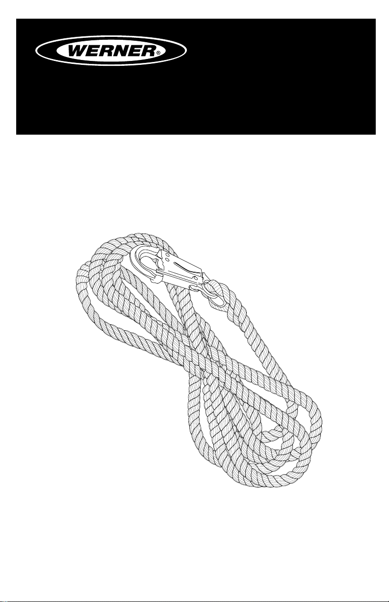
ROPE VERTICAL LIFELINE
Complies with ANSI Z359.1-2007,
OSHA 1910 and 1926 requirements.
CUERDA SALVAVIDAS VERTICAL DE FIBRAS
TRENZADAS
Cumple con las normas ANSI Z359.1-2007, OSHA 1910 y 1926.
(This manual applies to all rope vertical lifelines with
model numbers starting L201.)
(Este manual es para todas las cuerdas salvavidas
verticalescon numero de modelo comenzando en L201.)
Werner Fall Protection 724-588-2000
93 Werner Rd. 888-523-3371 toll free/ llamada gratuita
Greenville, PA 16125 888-456-8458 fax
Page 2
CAUTION!
If use of fall protection equipment is necessary then the work
environment is dangerous and potentially deadly. Werner Company
products are designed to eliminate as much of the hazard as possible
but can do that ONLY if they are used correctly. Use this equipment as
it was designed to be used, after appropriate training, under the direct
supervision of a competent person, according to the instructions
provided, and in accordance with OSHA and local safety regulations.
User MUST read and understand all cautions and instructions. Failure
to heed these guidelines could result in injury or even death. Please,
WORK SAFE! WORK SMART!
ENGLISH
Page 2
Page 3

ROPE VERTICAL LIFELINE
USER INSTRUCTIONS
Contents
I. BEFORE USING THE VERTICAL LIFELINES SYSTEM ................................... 4
a. Inspect ......................................................................................................................4
b. Compatibility ............................................................................................................5
c. Fall Protection Plan ..................................................................................................6
d. Training .....................................................................................................................8
II. TEMPORARY VERTICAL ROPE SYSTEM INSTALLATION AND USE ............ 8
a. Making a Connection ...............................................................................................9
b. Anchorage Strength ..............................................................................................10
III. USE WARNINGS, RESTRICTIONS AND CAUTIONS ................................... 11
a. Purpose ..................................................................................................................11
b. Limitations..............................................................................................................12
IV. LABELS/IDENTIFICATION/INSPECTION RECORDS .................................. 14
V. EQUIPMENT RECORDS ................................................................................15
VI. INSPECTION RECORDS .............................................................................. 15
Page 3
ENGLISH
Page 4
Warning:
This product is just one part of a personal fall arrest, work positioning,
travel restraint, climbing or rescue system. It must be matched
correctly with other components to form a complete and functional
system. The user must understand the function of each of these
components and follow the manufacturer’s instructions for use for
each. The user must be provided these instructions, should read and
follow them, and consult the competent person who will supervise
his work if he has any questions about any part of the instructions.
The employer must provide training in the proper use, inspection, and
maintenance of all components in the system, and these instructions
can be used as part of that training. The equipment should be used
ONLY in accordance with these instructions, local ordinances and
codes, the applicable OSHA and ANSI standards, and the employer’s
safety plan.
This temporary rope system is designed to provide a connection
for users to an anchorage as they traverse any type of vertical
work or access, for both fall protection and fall restraint. They can
accommodate a variety of fall protection or rescue equipment that
might be required, so long as the rated capacity is not exceeded.
IF YOU HAVE ANY QUESTIONS ABOUT ANYTHING IN THESE
INSTRUCTIONS, THE EQUIPMENT, OR PROPER USE OF THE
EQUIPMENT, CONTACT WERNER CO. FOR MORE INFORMATION.
I. Before Using the Vertical Rope System
Before using this equipment the user should take certain steps to
ensure that it is in suitable condition and safe for use. Users must
read and understand these instructions. It is the employer’s obligation
to ensure that all users have been trained in safe work procedures as
well as in the use and limitations of fall protection equipment. All users
should be aware of and comply with all applicable OSHA, ANSI, CSA
and local or regional regulations concerning fall protection equipment
and its use.
a. Inspect
ENGLISH
Page 4
Examine all equipment thoroughly, daily before use by the user,
and periodically by a competent person who is not the user.
Page 5

ROPE VERTICAL LIFELINE
USER INSTRUCTIONS
1. Inspect lifeline hardware (snap hooks, ferrules, thimbles, etc.).
These items must not be damaged, broken or distorted. These
items must be free of sharp edges, burrs, cracks, worn parts, or
corrosion. Hook gates must move freely and lock upon closing.
2. Inspect the synthetic rope lifeline per the following:
i. Inspect rope for concentrated wear. Material must be free
of frayed strands, broken yarns, cuts, abrasions, burns, and
discoloration.
ii. The rope must be free of knots, excessive soiling, paint
build-up, and rust staining.
iii. Rope splices must be tight, with ve full tucks, and thimbles
must be held rmly by the splice.
iv. Check for chemical or heat damage; indicated by brown,
discolored, or brittle areas.
v. Check for ultraviolet damage; indicated by discoloration and
splinters and slivers along the rope surface.
vi. All of the above factors are known to reduce rope strength.
Damaged or questionable rope should be replaced.
vii. Verify the condition of each component. If any damage or
abnormalities are found the equipment should be removed
from service.
3. Inspect label. Labels must be present and fully legible.
4. Inspect each system component or subsystem according to
manufacturer ’s instructions.
5. Record the inspection date and results in the inspection log.
6. If inspection reveals an unsafe or defective condition, remove
equipment from service. A competent person should be
consulted to determine if that item is safe for continued use or if
it should be removed from service.
b. Compatibility
Werner Co. equipment is designed for use with Werner Co. approved
components and subsystems only. Substitutions or replacements
made with non-approved components or subsystems may
jeopardize compatibility of equipment and may affect the safety and
reliability of the complete system.
Page 5
ENGLISH
Page 6
IMPORTANT: The type of lifeline used is dependent upon the
application and compatibility requirements of other system
components. Compatible rope grabs must be used with Werner Co.
lifelines.
Connectors are considered to be compatible with connecting
elements when they have been designed to work together in
such a way that their sizes and shapes do not cause their gate
mechanisms to inadvertently open regardless of how they become
oriented. Contact Werner Co. if you have any questions about
compatibility. Connectors (hooks, carabiners, and D-rings) must be
capable of supporting at least 5,000 lbs. (22kN). Connectors must
be compatible with the anchorage or other system components.
Do not use equipment that is not compatible. Non-compatible
connectors may unintentionally disengage. Connectors must be
compatible in size, shape, and strength. Self locking snap hooks
and carabiners are required by ANSI Z359 and OSHA.
c. Fall Protection Plan
Plan your fall arrest or restraint system before using this equipment.
Consider all factors that will affect your safety during use of this
equipment. Consider the following points when planning your
system:
1. ANCHORAGE: Select a rigid anchorage point that is capable of
sustaining the loads specied. For fall arrest applications, select
anchorage locations that will minimize free fall and swing fall
hazards. For restraint applications, locate the anchorages such
that no vertical free fall is possible.
2. FREE FALL: To avoid increased free fall distance, do not work
above the anchorage level. Rig personal fall arrest systems
(PFAS) so that the free fall is limited to six feet (ANSI Z359.1).
Rig restraint systems such that no vertical free fall is possible.
3. FALL ARREST FORCES: The personal fall arrest system must
limit fall arrest forces to 1,800 lbs. Do not use a body belt for fall
arrest applications.
ENGLISH
Page 6
Page 7
ROPE VERTICAL LIFELINE
USER INSTRUCTIONS
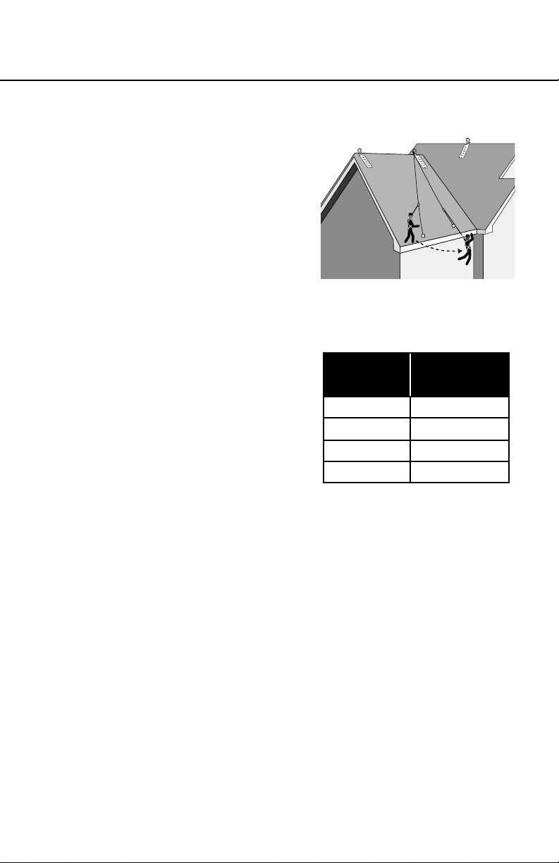
4. SWING FALLS: Swing falls
occur when the anchorage
point is not directly above the
point where a fall occurs. The
force of striking an object in a
swing fall may cause serious
injury. Minimize swing falls by
working as directly below the
anchorage point as possible.
Do not permit a swing fall if
injury could occur.
5. FALL CLEARANCE: Ensure sufficient clearance exists in your
fall path to prevent striking an object during a fall. The clearance
required is dependent upon
the subsystem (rope grab
and lanyard, rope grab
and carabiner) and lifeline
properties. The chart to the
right shows the approximate
elongation for new Werner Co.
lifelines in dry conditions. The
elongation specied is for an
applied static load of 1,800 lbs.
Wet ropes generally have more elongation than dry ropes. Allow
for additional elongation in wet or humid conditions. Lifeline
elongation must be considered when estimating fall clearance.
6. SHARP EDGES: Avoid working where your lifeline, lifeline
subsystem, or other system components will be in contact
with, or abrade against, unprotected sharp edges. Do not loop
a lifeline around small diameter structural members. If working
with this equipment around sharp edges is unavoidable, provide
protection by using a heavy pad over the exposed sharp edge.
7. RESCUE: Should a fall occur, the user (employer) must have a
rescue plan. If a worker falls and is forced to remain suspended
for any length of time, physical damage to the body or even
death can result. For this reason Werner, OSHA, ANSI, CSA
and most local regulations require that a rescue plan and the
means to implement the rescue plan are in place before use of
this equipment.
8. AFTER A FALL: Components which have been subjected to fall
arrest forces must be removed from service.
Lifeline
Length
30 ft 3.0 ft
50 ft 5.0 ft
75 ft 7.5 ft
100 ft 10.0 ft
Stretch
ENGLISH
Page 7
Page 8
9. GENERAL USE CONSIDERATIONS: Avoid working where your
lifeline may cross or tangle with that of another worker. Do not
allow your lifeline to pass under your arms or between your feet.
d. Training
OSHA, ANSI, and most local ordinances require that workers using
this product receive adequate training before use of this product.
These instructions and their entire contents should be a part of that
training.
II. Temporary Vertical Rope System Installation and Use:
Temporary vertical systems are connecting subsystems. These
systems are applicable for both fall arrest, typically when ladder
or scaffold climbing, working in a boatswain’s chair or similar, and
also for fall restraint, often on rooftop work, or other similar work
situations, to restrict movement and restrain access to a roof edge or
other danger of vertical freefall.
Warning:
Do not alter or intentionally misuse this equipment. Consult Werner
Co. when using this equipment in combination with components
or subsystems other than those described in this manual. Some
subsystem and component combinations may interfere with
the operation of this equipment. Use caution when using this
equipment around moving machinery, electrical hazards, chemical
hazards, and sharp edges.
Warning:
Do not use this system if you are unable to tolerate the impact of
a fall arrest. Age and tness can seriously affect your ability to
withstand a fall. Pregnant women and minors must not use this
equipment.
ENGLISH
Page 8
Page 9
ROPE VERTICAL LIFELINE
a. Making Connections
1. Only use self-locking snap hooks and carabiners with this
equipment. Only use connectors that are suitable to each
application. Ensure all connections are compatible in size, shape
and strength. Do not use equipment that is not compatible.
Ensure all connectors are fully closed and locked.
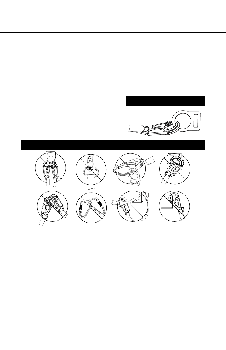
2. Werner Co. connectors (snap
hooks and carabiners) are
designed to be used only as
specied in each product’s
user’s instructions. See
inappropriate connections.
INAPPROPRIATE CONNECTIONS
A. B.
NO! NO! NO! NO!
D. E. F.
PROPER CONNECTIONS
USER INSTRUCTIONS
C.
NO!NO!NO!NO!
Werner Co. snap hooks and carabiners should NOT be
connected:
i. to a D-ring to which another connector is attached.
ii. in a manner that would result in a load on the gate. If the
connecting element that a snaphook or carabiner attaches
to is undersized or irregular in shape, a situation could occur
where the connecting element applies a force to the gate of
the snaphook or carabiner. This force may cause the gate
(of either a self-locking or a non-locking snaphook) to open,
allowing the snaphook or carabiner to disengage from the
connecting point.
Page 9
ENGLISH
Page 10

NOTE: Large throat opening snap hooks should not be
connected to standard size D-rings or similar objects which
will result in a load on the gate if the hook or D-ring twists
or rotates. Large throat snap hooks are designed for use on
xed structural elements such as rebar or cross members
that are not shaped in a way that can capture the gate of
the hook.
iii. in a false engagement, where features that protrude from
the snap hook or carabiner catch on the anchor and without
visual conrmation seems to be fully engaged to the anchor
point.
iv. to each other.
v. directly to webbing or rope lanyard or tie-back (unless
the manufacturer’s instructions for both the lanyard and
connector specically allow such a connection).
vi. to any object which is shaped or dimensioned such that the
snap hook or carabiner will not close and lock, or that roll-
out could occur.
b. Anchorage Strength
The anchorage strength required is dependent upon the application:
1. FALL ARREST: Anchorages used for personal fall arrest
systems must be capable of sustaining static loads in the
directions permitted by the personal fall arrest system of at least:
3,600 lbs. with certication of a qualied person; or 5,000 lbs.
without certication. See ANSI Z359.1 for certication denition.
Inappropriate Connections than one personal fall arrest system
is attached to an anchorage, the strengths stated above must
be met at each anchorage location independently. From OSHA
1926.500 and 1910.66: Anchorages used for attachment
of personal fall arrest systems shall be independent of any
anchorage being used to support or suspend platforms, and
capable of supporting at least 5,000 lbs. per user attached, or
be designed, installed, and used as part of a complete PFAS
which maintains a safety factor of at least two, and is under the
supervision of a qualied person.
ENGLISH
Page 10
2. RESTRAINT: The restraint system must be attached to an
anchorage capable of sustaining static loads in the directions
permitted by the restraint system of at least 3,000 lbs. When
more than restraint system is attached to an anchorage, the
Page 11

ROPE VERTICAL LIFELINE
USER INSTRUCTIONS
strengths stated above must be met at each anchorage location
independently.
3. CONNECTING TO AN ANCHORAGE OR ANCHORAGE
CONNECTOR: Lifelines or lifeline subsystems supplied with
connecting hooks should be connected to the anchorage in
accordance with section II.a.
4. CONNECTING ROPE GRAB TO LIFELINE: Follow the rope
grab manufacturer’s instructions for connecting the rope grab
to the lifeline. Compatible rope grabs must be used with these
lifelines.
IMPORTANT: Knots must not be used for load bearing end
terminations. See ANSI Z359. Some knots reduce lifeline
strength 50% or more.
5. END TERMINATION: If the user splices or forms end terminations,
proper procedures must be followed to ensure compatibility in
size, shape, and strength. Werner Co. is not responsible for
subsystems not manufactured by Werner Co.
6. AFTER USE: After use of this equipment, clean and store
according to the following guidelines:
i. Clean the lifeline with water and a mild detergent. Wipe
hardware dry with a clean, dry cloth and hang to air dry. Do
not force dry with heat. An excessive build-up of dirt, paint,
etc. may prevent the lifeline from working properly, and in
severe cases, weaken the rope.
ii. Store the lifeline in a cool, dry, clean environment, out of
direct sunlight. Avoid areas where chemical vapors may
be present. Thoroughly inspect the lifeline after extended
storage.
III. Use Warnings, Restrictions and Cautions
a. Purpose
Vertical lifelines and vertical lifeline subsystems are intended
to be used as part of a personal fall arrest or restraint system.
These lifelines and lifeline subsystems are not designed for use in
horizontal lifeline systems. Applications include: Inspection work,
construction, demolition, maintenance, oil production, conned
space rescue, window washing.
ENGLISH
Page 11
Page 12

1. FALL ARREST: The lifeline or lifeline subsystem is used as
part of a complete fall arrest system, which typically includes
a lifeline, rope grab, lanyard, and full body harness. Maximum
permissible free fall is six feet.
2. RESTRAINT: The lifeline or lifeline subsystem is used as part of
a restraint system. Restraint systems typically include a full body
harness and a lanyard to prevent the user from reaching a fall
hazard (leading edge roof work). No vertical free fall permitted.
b. LIMITATIONS
Consider the following application limitations before using this
equipment:
1. CAPACITY: This equipment is designed for use by persons with
a combined weight (person, clothing, tools, etc.) of no more
than 310 lbs. No more than one person may be connected to a
single lifeline.
2. FREE FALL: Personal fall arrest systems used with these
lifelines must be rigged to limit the free fall to six feet (according
to ANSI Z359.1). Restraint systems must be rigged such
that there is no possible vertical free fall. See subsystem
manufacturer’s instructions for more information.
3. FALL CLEARANCE: Ensure that adequate clearance exists
in your fall path to prevent striking an object. The amount of
clearance required is dependent on the type of connecting
subsystem (rope grab, lanyard), the applications anchorage
location, and the amount of stretch in the lifeline. See subsystem
manufacturer’s instructions for more information.
4. ENVIRONMENTAL HAZARDS: Use of this equipment in areas
where environmental hazards exist may require additional
precautions to reduce the possibility of injury to the user or
damage to the equipment. Hazards may include, but are not
limited to; high heat, caustic chemicals, corrosive environments,
high voltage power lines, explosive or toxic gases, moving
machinery, or sharp edges.
ENGLISH
Page 12
Page 13

ROPE VERTICAL LIFELINE
USER INSTRUCTIONS
IV. Labels/Identication/Inspection Records
a. All products should be inspected by the user thoroughly before
each use. Additional inspections by a competent person other than
the user should be conducted at intervals of no less than one year.
That interval should be shortened any time the product is used in a
harsh environment or is exposed to conditions such as chemicals,
abrasion, heat or any other factor that could affect the strength of
any of the materials or components.
b. This manual should always accompany the product, or be on le with
the employer for access when needed. Record the identication
details for the anchor and record the inspections in the inspection
log, below. It is important to maintain this log current, complete,
and available as needed.
Page 13
ENGLISH
Page 14

ENGLISH
Page 14
front back
Id label
Page 15

ROPE VERTICAL LIFELINE
V. Equipment Record
USER INSTRUCTIONS
PART NUMBER
SERIAL NUMBER
DATE
MANUFACTURED
PURCHASE DATE
ASSIGNED TO
SPECIFICATIONS
Werner Vertical Lifeline
Certied to meet ANSI Z359.1-2007, OSHA 1910 and 1926 standards and
regulations.
Individually bar coded model and serial numbers, location and date of
manufacture are on product label.
VI. Inspection Record
INSPECTION RECORD
DATE INSPECTOR PASS/FAILDATE INSPECTOR PASS/FAIL
Page 15
ENGLISH
Page 16

NOTES
ENGLISH
Page 16
Page 17

CUERDA SALVAVIDAS VERTICAL DE FIBRAS TRENZADAS
INSTRUCCIONES PARA EL USUARIO
¡PRECAUCIÓN!
Si el uso de equipos de protección contra caídas es necesario, entonces el
ambiente de trabajo es peligroso y potencialmente mortal. Los productos
Werner Company están diseñados para eliminar peligros tanto como sea
posible, pero SÓLO si estos productos se utilizan correctamente. Utilice este
equipo tal como fue diseñado para usarse, después de una capacitación
apropiada, bajo la supervisión directa de una persona calicada, de acuerdo
con las instrucciones suministradas, y de acuerdo con las regulaciones OSHA
y las regulaciones de seguridad locales. El usuario DEBE leer y entender todas
las precauciones e instrucciones. No tener en cuenta estas directrices podría
resultar en lesiones o incluso la muerte. Por favor, ¡TRABAJE DE MANERA
SEGURA! ¡TRABAJE DE MANERA INTELIGENTE!
Página 17
ESPAÑOL
Page 18

Contenido
I. ANTES DE UTILIZAR EL SISTEMA DE CUERDA
SALVAVIDAS VERTICAL ..................................................................................19
a. Inspeccione ............................................................................................................19
b. Compatibilidad .......................................................................................................20
c. Plan de protección contra caídas .........................................................................21
d. Capacitación ...........................................................................................................23
II. INSTALACIÓN Y USO DE SISTEMAS TEMPORALES DE
CUERDA VERTICAL ...................................................................................... 23
a. Realización de una conexión ................................................................................24
b. Resistencia del anclaje..........................................................................................25
III. TENGA EN CUENTA LAS ADVERTENCIAS, RESTRICCIONES Y
PRECAUCIONES ........................................................................................... 26
a. Propósito ..............................................................................................................26
b. Limitaciones ...........................................................................................................27
IV. ETIQUETAS/IDENTIFICACIÓN/REGISTROS DE INSPECCIÓN ..................28
V. REGISTROS DE EQUIPOS ............................................................................ 29
VI. REGISTROS DE INSPECCIÓN ..................................................................... 29
ESPAÑOL
Página 18
Page 19

CUERDA SALVAVIDAS VERTICAL DE FIBRAS TRENZADAS
INSTRUCCIONES PARA EL USUARIO
Advertencia:
Este producto es sólo una parte de un sistema personal de detención de caídas,
posicionamiento para el trabajo, limitación de recorrido, ascenso o rescate. Éste
debe combinarse correctamente con otros componentes para conformar un
sistema completo y funcional. El usuario debe entender la función de cada uno de
estos componentes y seguir las instrucciones del fabricante para el uso de cada
componente. El usuario debe recibir estas instrucciones, debe leerlas y seguirlas,
y consultar a la persona calicada que supervisará su trabajo si tiene alguna
pregunta acerca de cualquier parte de las instrucciones. El empleador debe
proporcionar capacitación sobre el uso apropiado, inspección y mantenimiento
de todos los componentes del sistema, y estas instrucciones pueden utilizarse
como parte de esa capacitación. El equipo SÓLO debe utilizarse de acuerdo
con estas instrucciones, ordenanzas y códigos locales, las normas OSHA y ANSI
aplicables, y el plan de seguridad del empleador.
Este sistema de cuerda temporal está diseñado para proporcionar a los usuarios
una conexión a un ancladero a medida que estos atraviesen cualquier tipo de
acceso o pieza vertical, para protección contra caídas y evitamiento de caídas.
Éstos pueden incorporar una variedad de protecciones contra caídas o equipos
de rescate que pudieran requerirse, siempre y cuando no se exceda la capacidad
nominal.
SI USTED TIENE ALGUNA PREGUNTA ACERCA DE ALGO DE ESTAS
INSTRUCCIONES, EL EQUIPO O EL USO APROPIADO DEL EQUIPO,
COMUNÍQUESE CON WERNER CO. PARA OBTENER MÁS INFORMACIÓN.
I. Antes de utilizar el sistema de cuerda vertical de bras
trenzadas
Antes de utilizar este equipo, el usuario debe realizar ciertos pasos para
garantizar que éste está en condiciones apropiadas y es seguro para su uso. Los
usuarios deben leer y entender estas instrucciones. Es obligación del empleador
garantizar que todos los usuarios hayan recibido capacitación sobre los
procedimientos de trabajo seguros y también sobre el uso y limitaciones de los
equipos de protección contra caídas. Todos los usuarios deben estar informados
acerca de y cumplir todas las normas OSHA, ANSI, CSA y las normas locales
o regionales relacionadas con los equipos de protección contra caídas y su uso.
a. Inspeccione
Todo el equipo debe ser examinado completamente, diariamente antes del uso,
por parte del usuario; y periódicamente por parte de una persona calicada
que no sea el usuario.
ESPAÑOL
Página 19
Page 20

ESPAÑOL
1. Inspeccione los herrajes de la cuerda salvavidas (ganchos de cierre
resortado, abrazaderas, guardacabos, etc.). Estos elementos no deben
estar dañados, rotos ni deformados. Estos elementos deben estar libres
de bordes losos, rebabas, grietas, piezas desgastadas o corrosión. Los
cierres de los ganchos deben moverse libremente y asegurar al momento
de cerrar.
2. Inspeccione la cuerda salvavidas de bras trenzadas sintéticas según lo
siguiente:
i. Inspeccione la cuerda en busca de desgaste focalizado. El material no
debe tener trenzas deshilachadas, hilos rotos, cortaduras, raspaduras,
quemaduras y decoloración.
ii. La cuerda no debe tener nudos, suciedad excesiva, acumulación de
pintura y manchas de óxido.
iii. Los empalmes de cuerda deben estar apretados, con cinco pliegues
completos, y los guardacabos deben estar sostenidos rmemente por
el empalme.
iv. Revise en busca de daño por sustancias químicas o calor; lo cual se
indica por áreas color café, decoloradas o quebradizas.
v. Revise en busca de daño por luz ultravioleta; lo cual se indica por
decoloración, astillas y pedacitos a lo largo de la supercie de la
cuerda.
vi. Se sabe que todos los factores anteriores reducen la resistencia de la
cuerda. La cuerda dañada o con posibles daños debe reemplazarse.
vii. Verique la condición de cada componente. Si se encuentra cualquier
daño o anormalidad, el equipo debe retirarse del servicio.
3. Inspeccione la etiqueta. Las etiquetas deben estar presentes y totalmente
legibles.
4. Inspeccione cada componente del sistema o subsistema de acuerdo con
las instrucciones del fabricante.
5. Registre la fecha y resultados de la inspección en el registro de inspección.
6. Si la inspección revela una condición insegura o defectuosa, saque del
servicio el equipo. Debe consultarse a una persona capacitada para
determinar si ese elemento es seguro para uso continuado o si debe
sacarse del servicio.
b. Compatibilidad
Los equipos Werner Co. están diseñados para uso sólo con componentes
y subsistemas aprobados por Werner Co. Las sustituciones o reemplazos
realizados con componentes o subsistemas no aprobados podrían arriesgar
la compatibilidad del equipo y podrían afectar la seguridad y conabilidad del
sistema completo.
Página 20
Page 21

CUERDA SALVAVIDAS VERTICAL DE FIBRAS TRENZADAS
INSTRUCCIONES PARA EL USUARIO
IMPORTANTE: El tipo de cuerda salvavidas que se utilice depende de la aplicación
y los requisitos de compatibilidad de los otros componentes del sistema.
Deben utilizarse dispositivos de agarre para cuerda trenzada compatibles con
las cuerdas salvavidas de Werner Co.
Los conectores se consideran compatibles con los elementos conectivos
cuando éstos han sido diseñados para trabajar en conjunto de tal manera que
sus tamaños y formas no causen que sus mecanismos de cierre se abran
inadvertidamente sin importar la manera como se orienten. Comuníquese
con Werner Co. si usted tiene alguna pregunta acerca de la compatibilidad.
Los conectores (ganchos, argollas rectangulares metálicas y los anillos en
‘D’) deben ser capaces de soportar 5.000 lbs. (22kN). Los conectores deben
ser compatibles con el anclaje u otros componentes del sistema. No utilice
equipos que no sean compatibles. Los conectores no compatibles podrían
desengancharse accidentalmente. Los conectores deben ser compatibles
en tamaño, forma y resistencia. Las normas ANSI Z359 y OSHA requieren
argollas metálicas y ganchos de cierre resortado auto-asegurables.
c. Plan de protección contra caídas
Antes de utilizar este equipo, planee su sistema de detención o evitamiento de
caídas. Considere todos los factores que afectarán su seguridad durante el uso
de este equipo. Considere los siguientes puntos al planear su sistema:
1. ANCLADERO: Seleccione un punto de anclaje rígido que sea capaz de
soportar las cargas especicadas. Para todas las aplicaciones de detención
de caídas, seleccione las ubicaciones de anclaje que minimizarán los
riesgos por caída libre o caída tipo columpio. Para las aplicaciones de
evitamiento de caídas, ubique los anclajes de modo que no sea posible
una caída libre vertical.
2. CAÍDA LIBRE: Para evitar una mayor distancia de caída libre, no trabaje
encima del nivel del anclaje. Instale los Sistemas Personales de Detención
de Caídas (SPDC) de modo que la caída libre se limite a 1.83 m (6 pies)
(ANSI Z359.1). Instale los sistemas de evitamiento de caídas de modo que
no sea posible una caída libre vertical.
3. FUERZAS DE DETENCIÓN DE CAÍDAS: El sistema personal de detención
de caídas debe limitar las fuerzas de detención de caídas a 1.800 lbs. No
utilice un cinturón de cuerpo para las aplicaciones de detención de caídas.
Página 21
ESPAÑOL
Page 22

ESPAÑOL
4. CAÍDAS TIPO COLUMPIO: Las
caídas tipo columpio ocurren
cuando el punto de anclaje no
está directamente encima del
punto donde ocurre una caída. La
fuerza al golpear un objeto en una
caída tipo columpio podría causar
lesiones graves. Minimice las
caídas tipo columpio trabajando tan
directamente debajo del punto de
anclaje como sea posible. No permita
una caída tipo columpio si hay posibilidad de ocurrencia de lesiones.
5. ESPACIO LIBRE DE CAÍDA: Asegúrese que exista un espacio libre
suciente en su trayectoria de caída para evitar golpear un objeto
durante una caída. El espacio libre
requerido depende del subsistema
(dispositivo de agarre para cuerda
trenzada y la cuerda, dispositivo
de agarre para cuerda trenzada y
la argolla rectangular metálica) y
de las propiedades de la cuerda
salvavidas. La tabla a la derecha
muestra el alargamiento aproximado
para las cuerdas salvavidas nuevas
Longitud de
la cuerda
Alargamiento
salvavidas
9,1 m (30 pies) ,91 m (3.0 pies)
15 m (50 pies) 1,5 m (5.0 pies)
22.9 m (75 pies) 2.3 m (7.5 pies)
30.5 m (100 pies) 3.1 m (10 pies)
Werner Co. en condiciones secas. El
alargamiento especicado es para una carga estática aplicada de 1.800 lbs.
Las cuerdas húmedas generalmente tienen mayor alargamiento que las
cuerdas secas. Tenga en cuenta un alargamiento adicional en condiciones
húmedas o mojadas. Al calcular el espacio libre para caídas, debe tenerse
en cuenta el alargamiento de la cuerda salvavidas.
6. BORDES FILOSOS: Evite trabajar en lugares donde su cuerda salvavidas,
subsistema de la cuerda salvavidas, u otros componentes del sistema
harán contacto con, o se desgastarán contra, bordes losos expuestos.
No enrolle una cuerda salvavidas alrededor de miembros estructurales de
diámetro pequeño. Si no se puede evitar trabajar con este equipo alrededor
de bordes losos, proporcione protección utilizando una almohadilla gruesa
sobre el borde loso expuesto.
7. RESCATE: Si ocurre una caída, el usuario (empleador) debe tener un
plan de rescate. Si un trabajador cae y queda obligado a permanecer
suspendido durante cualquier período de tiempo, podría producirse daño
físico o incluso la muerte. Por este motivo; Werner, las regulaciones de
OSHA, ANSI, CSA, y la mayoría de las regulaciones locales exigen la
existencia de un plan de rescate y los medios para ejecutar un plan de
rescate, antes del uso de este equipo.
Página 22
Page 23

CUERDA SALVAVIDAS VERTICAL DE FIBRAS TRENZADAS
INSTRUCCIONES PARA EL USUARIO
8. DESPUÉS DE UNA CAÍDA: Los componentes que han sido sometidos a
fuerzas de detención de caídas deben sacarse del servicio.
9. CONSIDERACIONES GENERALES DE USO: Evite trabajar donde su
cuerda salvavidas pudiera atravesarse o enredarse con la cuerda de otro
trabajador. No permita que su cuerda salvavidas pase debajo de sus brazos
o entre sus pies.
d. Capacitación
Las regulaciones OSHA, ANSI, y la mayoría de las regulaciones locales exigen
que los trabajadores que utilicen este producto deben recibir capacitación
adecuada antes del uso de este producto. Estas instrucciones y su contenido
completo deben ser parte de esa capacitación.
II. Instalación y uso de sistemas temporales de cuerda vertical:
Los sistemas temporales de cuerda vertical son subsistemas conectivos. Estos
sistemas son aplicables para la detención de caídas, normalmente al subir por
una escalera o a un andamio, al trabajar en una silla de contramaestre o similar,
y también para el evitamiento de caídas, frecuentemente en trabajos en tejados/
techos, u otras situaciones de trabajo similares, para restringir el movimiento
y restringir el acceso a bordes de techo u otros peligros de caída libre vertical.
Advertencia:
No altere ni utilice incorrectamente intencionalmente este equipo. Consulte
con Werner Co. al utilizar este equipo en conjunto con componentes o
subsistemas diferentes a los descritos en este manual. Algunos subsistemas
y combinaciones de componentes podrían interferir con la operación de este
equipo. Tenga precaución al utilizar este equipo alrededor de máquinas en
movimiento, peligros eléctricos, peligros químicos y bordes losos.
Advertencia:
No utilice este sistema si usted no puede tolerar el impacto de una detención
de caída. La edad y la condición física pueden afectar seriamente su capacidad
para soportar una caída. Las mujeres embarazadas y los menores de edad no
deben utilizar este equipo.
Página 23
ESPAÑOL
Page 24

a. Realización de las conexiones
1. Con este equipo, sólo utilice argollas rectangulares metálicas y ganchos
de cierre resortado auto-asegurables. Sólo utilice conectores que sean
apropiados para cada aplicación. Verique que todas las conexiones son
compatibles en tamaño, forma y resistencia. No utilice equipos que no sean
compatibles. Verique que todos conectores están totalmente cerrados y
asegurados.
2. Los conectores Werner Co.
CONEXIONES APROPIADAS
(ganchos de cierre resortado y
argollas rectangulares metálicas)
están diseñados para utilizarse
únicamente según se especica en
las instrucciones para usuario de
cada producto. Vea las conexiones
inapropiadas.
CONEXIONES INAPROPIADAS
A. B.
NO! NO! NO! NO!
D. E. F.
C.
ESPAÑOL
Página 24
NO!NO!NO!NO!
Los ganchos de cierre resortado y las argollas rectangulares metálicas de
Werner Co. NO deben conectarse:
i. a un anillo en ‘D’ al cual está sujetado otro conector.
ii. de tal manera que se produzca carga sobre el cierre. Si el elemento
conectivo al cual se sujeta un gancho de cierre resortado o una
argolla rectangular metálica es de tamaño inferior o tiene forma
irregular, podría ocurrir un problema cuando el elemento conectivo
aplique una fuerza al cierre del gancho de cierre resortado o la argolla
rectangular metálica. Esta fuerza podría causar que se abra el cierre
(de un gancho de cierre resortado auto-asegurable o no-asegurable),
permitiendo que el gancho de cierre resortado o la argolla rectangular
metálica se desenganche del punto de conexión.
Page 25

CUERDA SALVAVIDAS VERTICAL DE FIBRAS TRENZADAS
INSTRUCCIONES PARA EL USUARIO
NOTA: Los ganchos de cierre resortado que se abren hasta una garganta
grande no deben conectarse a anillos en ‘D’ de tamaño estándar u
objetos similares, lo cual resultará en una carga sobre el cierre si el
gancho o anillo en ‘D’ gira o rota. Los ganchos de cierre resortado
de garganta grande están diseñados para uso en elementos
estructurales jos tales como barras de refuerzo o travesaños que no
tengan una forma que puedan atrapar el cierre del gancho.
iii. en un enganche falso, donde las características que sobresalen
del gancho de cierre resortado o la argolla rectangular metálica se
agarran al anclaje, y sin conrmación visual parece estar totalmente
enganchado al punto de anclaje.
iv. uno al otro.
v. directamente a una correa tejida o cuerda de bras trenzadas o
amarre sobre sí mismo (a menos que las instrucciones del fabricante
de la cuerda y el conector permitan especícamente dicha conexión).
vi. a cualquier objeto que tenga una forma o dimensiones tales que el
gancho de cierre resortado o la argolla rectangular metálica no se
cierren ni aseguren, y que pudiera ocurrir rodaje.
b. Resistencia del anclaje
La resistencia requerida del anclaje depende de la aplicación:
1. DETENCIÓN DE CAÍDAS: Los ancladeros utilizados para sistemas
personales de detención de caídas deben ser capaces de sostener
cargas estáticas en las direcciones permitidas por el sistema personal de
detención de caídas de al menos: 3.600 lbs. con certicación por parte de
una persona capacitada; ó 5.000 lbs. sin certicación. Consulte la norma
ANSI Z359.1 para obtener la denición de certicación. Cuando se sujeta
más de un (1) sistema personal de detención de caídas a un ancladero, las
resistencias indicadas anteriormente deben cumplirse en cada ubicación
de anclaje de manera independiente. De OSHA 1926.500 y 1910.66: Los
ancladeros utilizados para sujeción de sistemas personales de detención
de caídas deberán ser independientes de cualquier ancladero que se esté
utilizando para soportar o suspender plataformas, y deberán ser capaces
de soportar al menos 5.000 lbs. por cada usuario sujetado, o diseñarse,
instalarse y utilizarse como parte de un sistema completo personal de
detención de caídas que mantenga un factor de seguridad de dos como
mínimo, y estar bajo la supervisión de una persona capacitada.
2. EVITAMIENTO DE CAÍDAS: El sistema de evitamiento de caídas desde
sujetarse a un ancladero capaz de sostener cargas estáticas en las
direcciones permitidas por el sistema de evitamiento de caídas de al menos
3.000 lbs. Cuando se sujeta más de un sistema de evitamiento de caídas a
un ancladero, las resistencias indicadas anteriormente deben cumplirse en
cada ubicación de anclaje de manera independiente.
ESPAÑOL
Página 25
Page 26

3. CONEXIÓN A UN ANCLAJE O CONECTOR DE ANCLAJE: Las cuerdas
salvavidas o los subsistemas de cuerdas salvavidas equipados con
ganchos conectivos deben conectarse al anclaje de acuerdo con la sección
II.a.
4. CONEXIÓN DE DISPOSITIVO DE AGARRE PARA CUERDA TRENZADA
A LA CUERDA SALVAVIDAS: Siga las instrucciones del fabricante del
dispositivo de agarre para cuerda trenzada para conectar el dispositivo
de agarre para cuerda trenzada a la cuerda salvavidas. Deben utilizarse
dispositivos de agarre para cuerda trenzada compatibles con estas cuerdas
salvavidas.
IMPORTANTE: No deben utilizarse nudos para realizar terminaciones de
extremo de soporte de carga. Vea la norma ANSI Z359. Algunos nudos
reducen la resistencia de la cuerda salvavidas en 50% o más.
5. TERMINACIÓN DE EXTREMO: Si el usuario realiza empalmes o forma
terminaciones de extremo, deben seguirse procedimientos apropiados
para garantizar la compatibilidad en tamaño, forma y resistencia. Werner
Co. no es responsable por subsistemas no fabricados por Werner Co.
6. DESPUÉS DEL USO: Después del uso de este equipo, limpie y guarde de
acuerdo con las siguientes directrices:
i. Limpie la cuerda salvavidas con agua y detergente suave. Seque
los herrajes con un trapo limpio y seco, y cuelgue para secar al
aire. No fuerce el secado con calor. Una acumulación excesiva de
suciedad, pintura, etc. podría evitar que la cuerda salvavidas funcione
apropiadamente, y en casos severos, podría debilitar la cuerda.
ii. Guarde la cuerda salvavidas en un ambiente fresco, seco y limpio,
alejado de la luz solar directa. Evite los lugares donde pudieran haber
vapores de productos químicos. Inspeccione detenidamente la cuerda
salvavidas después de su almacenamiento durante un periodo de
tiempo prolongado.
III. Tenga en cuenta las advertencias, restricciones y
precauciones
a. Propósito
Las cuerdas salvavidas verticales y los subsistemas de las cuerdas salvavidas
verticales están diseñados para utilizarse como parte de un sistema personal
de detención de caídas o de evitamiento de caídas. Estas cuerdas salvavidas
y los subsistemas de las cuerdas salvavidas no están diseñados para uso
en sistemas horizontales de cuerdas salvavidas. Las aplicaciones incluyen:
Trabajo de inspección, construcción, demolición, mantenimiento, producción
ESPAÑOL
de petróleo, rescate en espacios connados, lavado de ventanas.
Página 26
Page 27

CUERDA SALVAVIDAS VERTICAL DE FIBRAS TRENZADAS
INSTRUCCIONES PARA EL USUARIO
1. DETENCIÓN DE CAÍDAS: La cuerda salvavidas o el subsistema de
la cuerda salvavidas se utiliza como parte de un sistema completo de
detención de caídas, que normalmente incluye una cuerda salvavidas, un
dispositivo de agarre para cuerda trenzada, una cuerda, y un arnés de
cuerpo completo. La caída libre máxima permisible es de 1.83 m (6 pies).
2. EVITAMIENTO DE CAÍDAS: La cuerda salvavidas o el subsistema de la
cuerda salvavidas se utiliza como parte de un sistema de evitamiento de
caídas. Los sistemas de evitamiento de caídas normalmente incluyen
un arnés de cuerpo completo y una cuerda para evitar que el usuario se
acerque a un peligro de caída (trabajo en techo de borde delantero). No se
permite caída libre vertical.
b. LIMITACIONES
Antes de utilizar este equipo, tenga en cuenta las siguientes limitaciones de
aplicación:
1. CAPACIDAD: Este equipo está diseñado para uso por personas con un
peso combinado (persona, ropa, herramientas, etc.) no superior a 310 lbs.
No puede conectarse más de una (1) persona a una (1) cuerda salvavidas.
2. CAÍDA LIBRE: Deben instalarse sistemas personales de detención de
caídas, utilizados con estas cuerdas salvavidas, para limitar la caída
libre a 1.83 m (6 pies) (de acuerdo con la norma ANSI Z359.1). Deben
instalarse sistemas de evitamiento de caídas de modo que no haya
posibilidad de caídas libres verticales. Vea las instrucciones del fabricante
del subsistema para obtener más información.
3. ESPACIO LIBRE DE CAÍDA: Verique que existe un espacio libre
apropiado en la trayectoria de caída para evitar golpes con un objeto.
La cantidad de espacio libre requerida depende del tipo de subsistema
conectivo (dispositivo de agarre para cuerda trenzada, cuerda), las
aplicaciones, la ubicación del anclaje, y la cantidad de alargamiento de
la cuerda salvavidas. Vea las instrucciones del fabricante del subsistema
para obtener más información.
4. RIESGOS AMBIENTALES: El uso de este equipo en lugares donde
existan peligros ambientales podría requerir precauciones adicionales
para reducir la posibilidad de lesiones del usuario o daño del equipo. Los
peligros podrían incluir, pero no se limitan a; alta temperatura, productos
químicos cáusticos, ambientes corrosivos, cables de energía de alto
voltaje, gases explosivos o tóxicos, maquinaria en movimiento o bordes
losos.
Página 27
ESPAÑOL
Page 28

IV. Etiquetas/Identicación/Registros de inspección
a. Todos los productos deben ser inspeccionados completamente por el usuario
antes de cada uso. Una persona calicada, diferente al usuario, debe realizar
inspecciones adicionales en intervalos no inferiores a un (1) año. Ese intervalo
debe acortarse cada vez que el producto se utiliza en un ambiente agresivo
o se expone a condiciones tales como productos químicos, abrasión, calor o
cualquier otro factor que pudiera afectar la resistencia de cualquiera de los
materiales o componentes.
b. Este manual siempre debe acompañar el producto o estar en los archivos
del empleador para consultarlo cuando se requiera. Registre los detalles de
identicación del anclaje y registre las inspecciones en el siguiente registro
de inspección. Es importante mantener este registro actualizado, completo y
disponible según se requiera.
ESPAÑOL
Página 28
Page 29

CUERDA SALVAVIDAS VERTICAL DE FIBRAS TRENZADAS
INSTRUCCIONES PARA EL USUARIO
parte delantera parte trasera
Etiqueta de identicación
ESPAÑOL
Página 29
Page 30

V. Registro del equipo
NÚMERO DE
PIEZA
NÚMERO DE SERIE
FECHA DE
FABRICACIÓN
FECHA DE COMPRA
ASIGNADO A
ESPECIFICACIONES
Cuerda salvavidas vertical de Werner
Certicada para cumplir las regulaciones y normas ANSI Z359.1-2007, OSHA
1910 y 1926.
Los números de modelo y números de serie, sitio y fecha de fabricación, con
código de barras individual, están en la etiqueta del producto.
VI. Registro de inspección
REGISTRO DE INSPECCIÓN
FECHA INSPECTOR APROBADO/
NO-APROBADO
FECHA INSPECTOR APROBADO/
NO-APROBADO
ESPAÑOL
Página 30
Page 31

CUERDA SALVAVIDAS VERTICAL DE FIBRAS TRENZADAS
INSTRUCCIONES PARA EL USUARIO
NOTAS
Page 32

Werner Co. Fall Protection
93 Werner Rd. Greenville, PA 16125
724-588-2000 • 888-523-3371 toll free/ llamada gratuita • 888-456-8458 fax
PN103769-01 ©2012 Werner Co. 1/12 Rev A
 Loading...