

Page 1
FALL PROTECTION
PROTECCIÓN CONTRA CAÍDAS
USER INSTRUCTIONS
INSTRUCCIONES PARA EL USUARIO
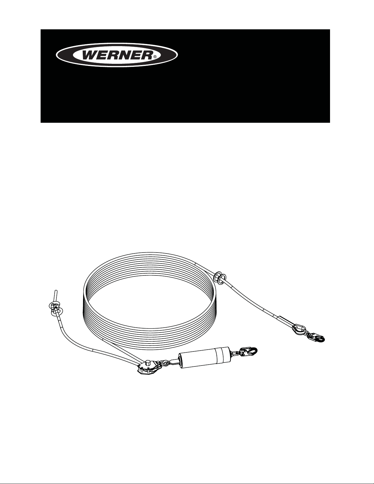
SYNTHETIC ROPE HORIZONTAL
LIFELINE
Complies with OSHA 29 CFR 1910 and 1926 regulations and requirements.
CUERDA SALVAVIDAS
HORIZONTAL SINTETICA
Cumple con los reglamentos y requisitos de OSHA 29 CFR 1910 y 1926
Models/Modelos: L100030, L100060, L100100, L102030, L102060, L102100,
L120030, L120060, L120100, L122030, L122060, L122100
Werner Co. Fall Protection 724-588-2000
93 Werner Rd. 888-523-3371 toll free/ llamada gratuita
Greenville, PA 16125 888-456-8458 fax
Page 2
WARNING!
Compliant fall protection equipment must only be used as it was designed.
Users MUST read and follow all user instructions provided with the product.
Before using a fall arrest system, users must be trained in the safe use of
the system, as required by OSHA 29 CFR 1910.66 and 1926.503, or local
safety regulations. Misuse or failure to heed these warnings and
instructions may result in injury or even death.
WORK SAFE! WORK SMART!
IF YOU HAVE ANY QUESTIONS ABOUT THE PROPER USE OF THE EQUIPMENT,
SEE YOUR SUPERVISOR, USER INSTRUCTIONS, OR CONTACT WERNER CO.
FOR MORE INFORMATION.
WARNING!
WARNING!
Over- or under-tensioning may cause excessive wear or damage to system
components and/or increased fall clearance requirements.
Never attach the unused leg of the lanyard back to the full body harness at
any location other than a lanyard keeper.
Never use combinations of components or subsystems that may affect, or
interfere with, the safe function of each other.
All components of the Synthetic Rope Horizontal Lifeline must be inspected
prior to each use in accordance with the requirements of OSHA 29 CFR
1910.66 and 1926.502.
If inspection reveals any defect, inadequate maintenance, or unsafe
condition, remove from service until a “quali ed” person, as de ned by
OSHA 29 CFR 1910.26(m), can determine the need for authorized repair or
disposal.
Any equipment that has been subjected to the forces of arresting a fall, or
that has a deployed load indicator, must be removed from service until a
“quali ed person” can determine the need for authorized repair or disposal.
ENGLISH
Page 2
Page 3
SYNTHETIC ROPE HORIZONTAL LIFELINE
USER INSTRUCTIONS
WARNING!
The installation height of the Synthetic Rope Horizontal Lifeline is
dependent on the type of connecting subsystem attached. See CLEARANCE
REQUIREMENTS.
When using SRLs as connecting devices, the Synthetic Rope Horizontal
Lifeline must be installed. The installation height of the Synthetic Rope
Horizontal Lifeline and type of connecting subsystem attached both directly
affect the fall clearance requirement.
When using SRLs, the increased potential for swing fall should be assessed
in addition to the required fall clearance. Longer Self Retracting Lifelines
(greater than 30 feet) may increase the potential for additional swing fall or
free fall.
USE INSTRUCTIONS AND LIMITATIONS
IMPORTANT
Before use, the user must read and understand these User Instructions. Keep
these User Instructions for reference.
PURPOSE
The Synthetic Rope Horizontal Lifeline is an engineered exible horizontal lifeline
system, designed to be used as part of a complete personal fall arrest system, to
provide horizontal mobility for up to two users and help limit the fall arrest forces
in the event of a fall.
USE INSTRUCTIONS
1. Failure to follow all instructions and limitations on the use of the Synthetic
Rope Horizontal Lifeline may result in serious personal injury or death.
2. Before using a personal fall arrest system, employees must be trained in
accordance with the requirements of OSHA 29 CFR 1910.66 in the safe use
of the system and its components.
3. Personal fall arrest systems, including the Synthetic Rope Horizontal
Lifeline, must be inspected prior to each use for wear, damage, and other
deterioration. Defective components must be immediately removed from
service, in accordance with the requirements of OSHA 29 CFR 1910.66 and
1926.502.
ENGLISH
Page 3
Page 4

4. The complete fall protection system must be planned (including all
components, calculating fall clearance, and swing fall) before using.
5. Users must have a rescue plan, and the means to implement it, that provides
for the prompt rescue of employees in the event of a fall, or assures that
employees are able to rescue themselves.
6. Store the Synthetic Rope Horizontal Lifeline in a cool, dry, clean environment
and out of direct sunlight when not in use.
7. After a fall occurs on the system, immediately remove from service until a
“quali ed person” can make the determination for reuse or disposal.
USE LIMITATIONS
1. CAPACITY: The Synthetic Rope Horizontal Lifeline is designed for up to two
users at one time, per system, with a capacity (including clothing, tools, etc.)
up to 400 pounds (181 kg) total working weight per user, in conjunction with
compatable connecting components.
2. SPAN: The Synthetic Rope Horizontal Lifeline can be adjusted from a
minimum of 10 feet (3.05m) to the maximum allowed by the included length
of rope.
3. SUPERVISION: In accordance with the requirements of OSHA 29 CFR
1910.66, and 1926.502, the Synthetic Rope Horizontal Lifeline must be
installed and used under the supervision of a “quali ed” person as de ned by
OSHA 29 CFR 1926.32(m).
4. EXTENDED SUSPENSION: The Synthetic Rope Horizontal Lifeline is not
intended for use in extended suspension applications.
5. CORROSION: Do not leave the Synthetic Rope Horizontal Lifeline in
environments where corrosion of metal parts could take place as a result
of vapors from organic materials. Use near seawater or other corrosive
environments may require more frequent inspections to ensure corrosion
damage is not affecting the performance of the product.
6. CHEMICAL HAZARDS: Solutions containing acids, alkali, or other caustic
chemicals, especially at elevated temperatures, may cause damage to the
Synthetic Rope Horizontal Lifeline. When working with such chemicals,
frequent inspection of this equipment must be performed. Contact Werner
Co. with any questions concerning the use of the Synthetic Rope Horizontal
Lifeline around chemical hazards.
7. EXTREME TEMPERATURE: The Synthetic Rope Horizontal Lifeline is
designed to be used in temperatures ranging from -40ºF to +130ºF (-40°C to
ENGLISH
Page 4
Page 5

SYNTHETIC ROPE HORIZONTAL LIFELINE
USER INSTRUCTIONS
+54°C). Protection should be provided for Synthetic Rope Horizontal Lifeline
when used near welding, metal cutting or similar activities. Contact Werner
Co. with any questions concerning high temperature environments.
8. ELECTRICAL HAZARDS: Use extreme caution when working near high
voltage power lines due to the possibility of electric current owing through
the Synthetic Rope Horizontal Lifeline or connecting components.
9. ANCHORAGES: The end anchorage must be capable of supporting loads
applied in all directions of 5,000 pounds (22.2kN), twice the maximum arrest
load.
10. COMPONENT COMPATIBILITY: Only components approved by Werner Co.
may be used with the Synthetic Rope Horizontal Lifeline.
11. SUBSYSTEMS: Only connecting subsystems that limit the maximum arrest
force to less than 1,800 pounds (8kN) may be used with the Synthetic Rope
Horizontal Lifeline.
12. HEALTH: Minors, pregnant women and anyone with a history of either back
or neck problems should not use this equipment.
13. TRAINING: Do not use or install the Synthetic Rope Horizontal Lifeline
without proper training from a “competent person” as de ned by OSHA’s 29
CFR 1926.32(f).
14. REPAIRS: Only Werner Co., or persons or entities authorized in writing by
Werner Co., may make repairs or alterations to the equipment.
ANCHORAGE REQUIREMENTS
ANCHORAGES
The Synthetic Rope Horizontal Lifeline incorporates an in-line energy absorber. It
is designed to limit the maximum arrest load to less than 2,500 pounds (11.1kN)
on the end anchorages. Therefore, the end anchorage must be rated at a
minimum strength of 5,000 pounds (22.2kN), twice the maximum arrest load.
All anchorages to which the Synthetic Rope Horizontal Lifeline attaches must
meet the requirements of ANSI Z359.1-2007 and OSHA 29 CFR 1910.66 and
1926.502.
OSHA states:
Anchorages used for attachment of personal fall arrest equipment shall be
independent of any anchorage being used to support or suspend platforms
ENGLISH
Page 5
Page 6

and capable of supporting at least 5,000 pounds (22.2 kN) per employee
attached, or shall be designed, installed, and used as part of a complete
personal fall arrest system which maintains a safety factor of at least two;
and under the supervision of a quali ed person.
ANSI Z359.1-2007 states that anchorages in a personal fall arrest system must
have a strength capable of sustaining static loads, applied in all permitted
directions by the system, of at least:
(a) two times the maximum arrest force permitted on the system when
certi cation exists, or
(b) 5,000 pounds (22.2kN) in the absence of certi cation
The strength in (a) and (b) must be multiplied by the number of personal fall
arrest systems attached to the anchorage, when more than one personal fall
arrest system is attached to the anchorage.
ANCHORAGE CONNECTORS
Anchorage connectors function as an interface between the anchorage and the
Synthetic Rope Horizontal Lifeline for the purpose of coupling the system to the
anchorage. The end anchorage connectors are designed to resist and transfer at
least twice the maximum arrest load to the end anchorages.
CONNECTION REQUIREMENTS
COMPATIBILITY LIMITATIONS
All connecting subsystems must only be coupled to compatible connectors.
OSHA 29 CFR 1926.502 prohibits snap hooks from being engaged to certain
objects unless two requirements are met: snap hook must be a locking type
and must be "designed for" making such a connection. Under OSHA 29
CFR 1926.502 "designed for" means that the manufacturer of the snap hook
speci cally designed the snap hook to be used to connect to the equipment in
question.
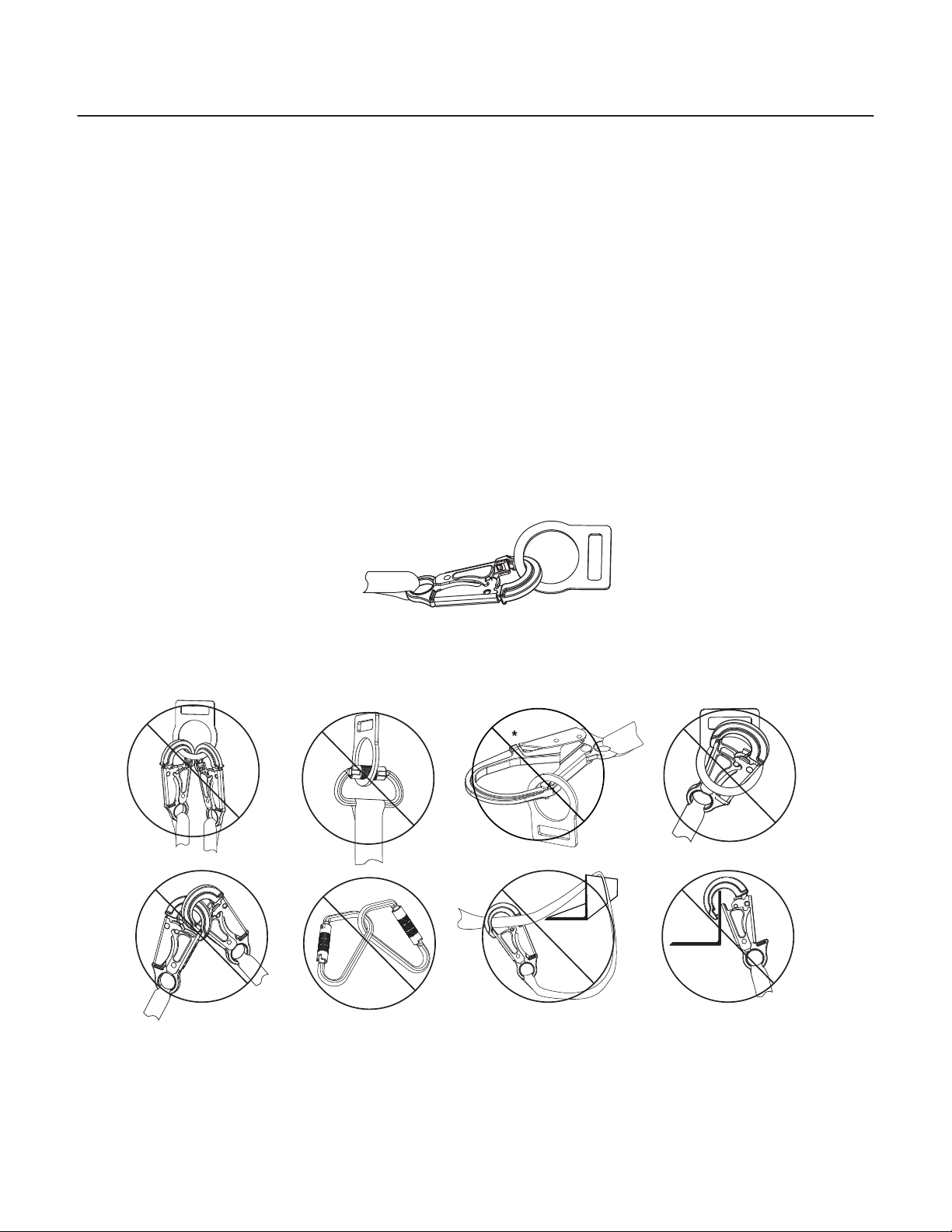
The following connections must be avoided, because they can result in rollout*
when a non locking snap hook is used:
ENGLISH
Page 6
Page 7
SYNTHETIC ROPE HORIZONTAL LIFELINE
USER INSTRUCTIONS
• Direct connection of a snap hook to horizontal lifeline.
• Two (or more) snap hooks connected to one D-ring.
• Two snap hooks connected to each other.
• A snap hook connected back on its integral lanyard.
• A snap hook connected to a webbing loop or webbing lanyard.
• Improper dimensions of the D-ring, rebar, or other connection point in
relation to the snap hook dimensions that would allow the snap hook
keeper to be depressed by a turning motion of the snap hook.
*Rollout: A process by which a snap hook or carabiner unintentionally
disengages from another connector or object to which it is coupled. (ANSI
Z359.0)
COMPATIBLE CONNECTIONS
INCOMPATIBLE CONNECTIONS
NO! NO! NO! NO!
SNAP HOOKS AND CARABINERS
Snap hooks and carabiners used in the Synthetic Rope Horizontal Lifeline,
marked with the ANSI Z359.1-07 or ANSI Z359.12-09 standard, are self-locking
with a minimum tensile break strength of 5,000 pounds (22.2kN), and a 3,600
pound (16kN) gate rating.
NO!NO!NO!NO!
ENGLISH
Page 7
Page 8
SYSTEM COMPONENTS
COMPATIBILITY LIMITATIONS
All components and subsystems used with the Synthetic Rope Horizontal Lifeline
have been tested as part of a pre-engineered exible horizontal lifeline system.
Only components and subsystems approved by Werner Co. are to be used with
the
Synthetic Rope Horizontal Lifeline.
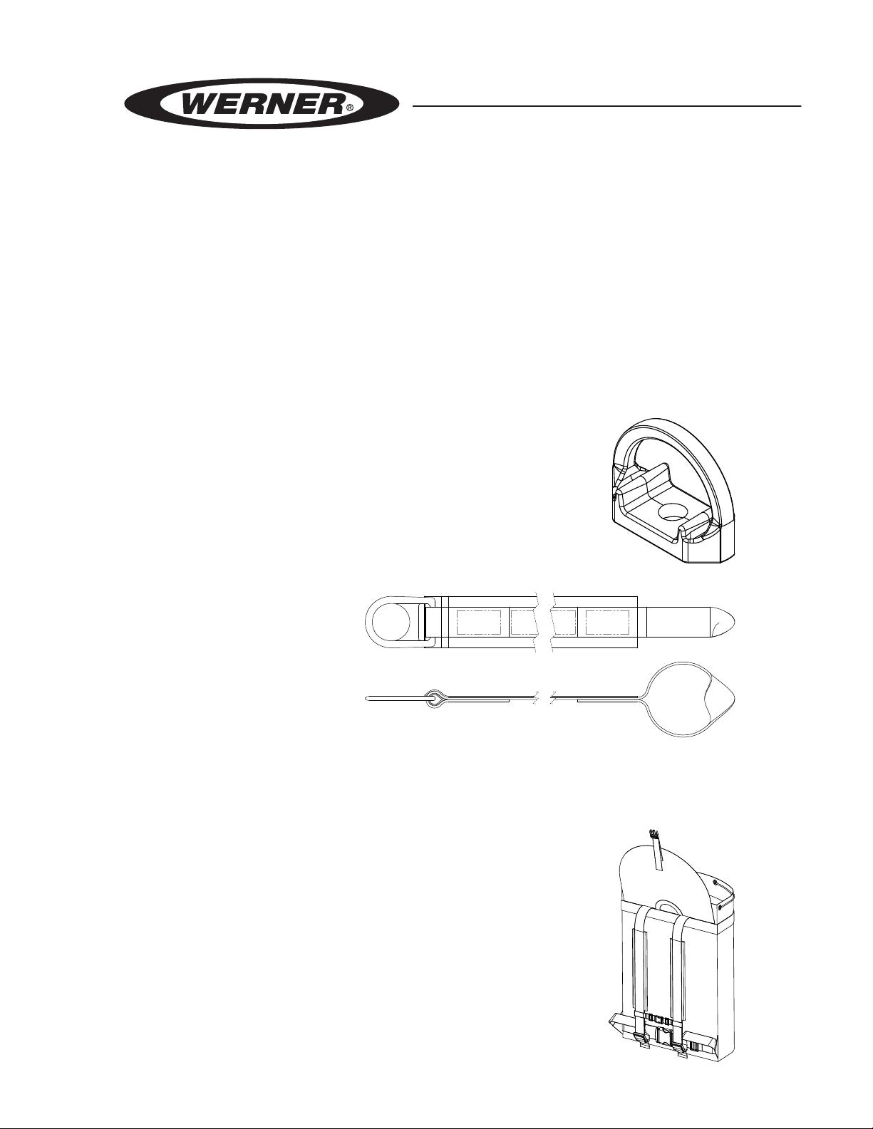
ANCHORAGE CONNECTORS
D-BOLT ANCHOR: A320001-WB
The 5,000 pound (22.2kN) anchorage connector made from high
tensile steel and attaches to anchor structure with a ⁄ inch -11
x 2¼ inch Grade 8 hex cap bolt, ⁄ inch-11 Grade 8 hex nut and
a ⁄ inch high alloy medium split lock washer. (A320001-WB
includes bolt, nut and lock washer)
CROSS ARM STRAP: A111104
Constructed with 1¾ inch
high strength polyester and 3
inch nylon, the 4 foot Cross
Arm Strap is designed to
wrap around a choke with the
12 inch soft loop to anchor
structures to creating a 5,000
pound
(22.2kN) anchor point.
ACCESSORIES
ACK PACK: K120004
B
The Back Pack is constructed of high strength polyester, with
a reinforced bottom to easily transport the
Horizontal Lifeline from job to job.
ENGLISH
Page 8
Synthetic Rope
Page 9
SYNTHETIC ROPE HORIZONTAL LIFELINE
USER INSTRUCTIONS
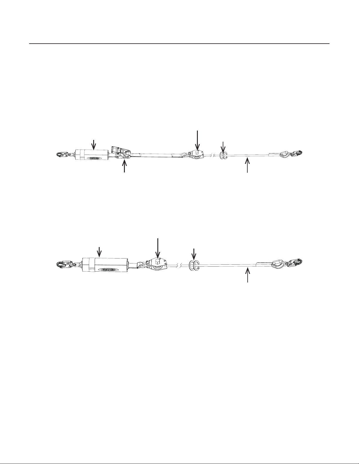
LIFELINE ASSEMBLY
SYSTEMS WITH TENSION-INDICATING RATCHET
L102030, L102060, L102100, L122030, L122060, L122100
Rope Tensioner
Shock Pack
O-Rings
Tension-Indicating
Ratchet
Rope
SYSTEMS WITHOUT TENSION-INDICATING RATCHET
L100030, L100060, L100100, L120030, L120060, L120100
Rope Tensioner
Shock Pack
O-Rings
Rope
SHOCK PACK
The shock pack is designed to limit the maximum arrest load to less than 2,500
lbf (11.1kN) on the end anchorages. The shock pack is constructed with polyester
web and tear web with a polyester cover that includes the labels with a protective
cover.
TENSION-INDICATING RATCHET
The Tension-Indicating Ratchet is constructed from high tensile steel and has a
10,000 pound
of the Tension-Indicating Ratchet is engineered to bend indicating when the
Synthetic Rope Horizontal Lifeline is properly tensioned. The Tension-Indicating
Ratchet includes high strength 1¾ inch (44.45mm) polyester webbing for 18
inches (0.45m) of adjustability.
(44.5kN) minimum breaking strength. The spring loaded handle
Page 9
ENGLISH
Page 10

LIFELINE ASSEMBLY CONTINUED
ROPE TENSIONER
The Rope Tensioner is used for coarse adjustment of the rope on systems
incorporating the Tension-Indicating Ratchet. For systems that do not incorporate
the Tension-Indicating Ratchet, the Rope Tensioner is designed to achieve
proper tension of the
constructed with high tensile steel.
Synthetic Rope Horizontal Lifeline. The Rope Tensioner is
ROPE
The low stretch ⁄ inch (15.9mm) Kernmantle rope is constructed with a nylon
strand core and a polyester jacket, providing a 10,000 pound
breaking strength. The abrasion-resistant jacket is designed to show damage
before the load carrying core becomes damaged. The rope should be removed
from service if the outer sheath is damaged. The rope comes with one end
nished (thimble and stitched) with a snap hook, and the other end is knotted to
prevent the rope from passing back through the Rope Tensioner.
(44.5kN) minimum
O-RINGS
The 2 inch (50.8mm) O-rings are made from high tensile steel and marked to
ANSI Z359.1-2007 and/or ANSI Z359.12-2012 with a minimum breaking strength
of 5,000 pounds
(22.2kN).
INSTALLATION
WARNING!
All components of the Synthetic Rope Horizontal Lifeline
must be inspected prior to each use in accordance with
the requirements of OSHA 29 CFR 1910.66 and 1926.502.
BEFORE EACH USE
Users must have a rescue plan, and the means to implement it, that provides for
the prompt rescue of employees in the event of a fall or assures that employees
are able to rescue themselves.
The user must read and understand these User Instructions, as well as the
User Instructions for every component and subsystem of the personal fall arrest
system.
ENGLISH
Page 10
Page 11
SYNTHETIC ROPE HORIZONTAL LIFELINE
USER INSTRUCTIONS
The entire Synthetic Rope Horizontal Lifeline, and its subsystems, must be
inspected prior to each use. See INSPECTION.
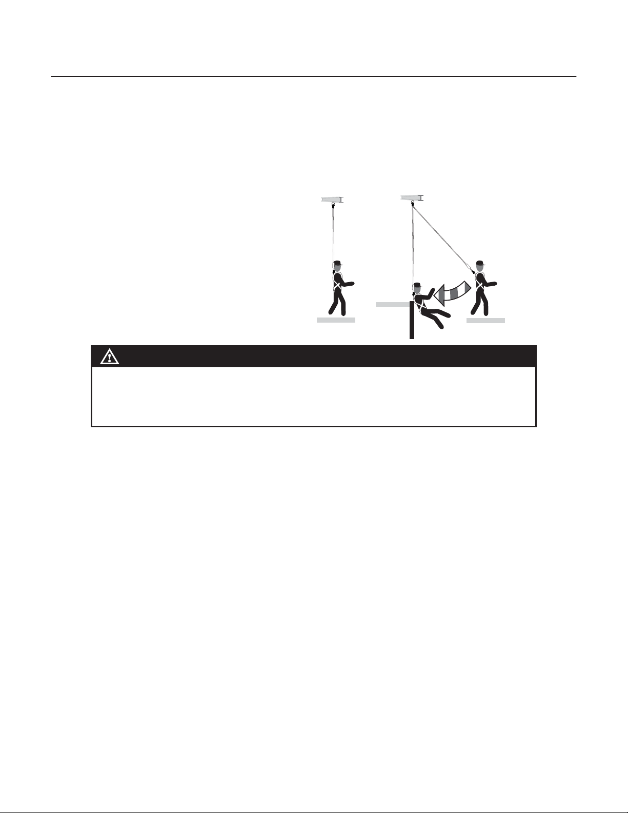
SWING FALLS
To minimize the possibility of a swing
fall, work as directly under or adjacent
to the Synthetic Rope Horizontal
Lifeline as possible. Striking objects
horizontally, due to the pendulum
affect, may cause serious injury. Swing
falls also increase the vertical fall
distance of a worker, compared to a
fall directly below the connection point.
See CLEARANCE REQUIREMENTS.
WARNING!
Anchorages
Correct Incorrect
SWING FALL
HAZARD
The installation height of the Synthetic Rope Horizontal
Lifeline is dependent on the type of connecting
subsystem attached. See CLEARANCE REQUIREMENTS.
STEP 1A: INSTALL CROSS ARM STRAP ANCHORAGE CONNECTOR
With labels on the outward facing surface of the Cross Arm Strap wrap web
around the anchorage
the web loop on the other end. Wrap as many times as necessary to achieve
desired length. Pull small D-ring to tighten (choke) the anchorage. The small
D-ring is the anchorage connector at the connection point.
structure and pass the small D-ring on one end through
STEP 1B: INSTALL D-BOLT ANCHORAGE CONNECTOR
Drill a ⁄ inch (17mm) hole where needed in the anchorage structure using a
suitable drill bit for penetration. Remove any burred edges from the structure.
Attach the D-Bolt Anchorage Connector using supplied 5⁄8 inch -11 x 2 inch
Grade 8 steel bolt, nut and lock washer. Insert supplied bolt through D-Bolt and
pre-drilled hole. Ensure bolt is pushed through completely and back surface
of the D-Bolt is ush against the anchorage structure. Slide the supplied lock
washer over the threads of the bolt until the washer is against the surface of the
anchorage structure. Thread nut onto bolt until it meets washer. Ensure D-Bolt is
oriented correctly and torque to 125 lbf-ft (17.3kgf-m).
Page 11
ENGLISH
Page 12
STEP 2: CONNECT SNAP HOOK END OF ROPE
Attach the snap hook that is connected to the end of the rope to the D-ring of the
Cross Arm Strap or the D-Bolt anchorage connector. This end of the system is the
dead-end of the Synthetic Rope Horizontal Lifeline system.
STEP 3: CONNECT SNAP HOOK ON SHOCK PACK
Connect the swivel snap hook attached to the shock pack to the remaining
anchorage connector (D-ring of the cross arm strap or the D-Bolt). This end of
the system is the live end of the Synthetic Rope Horizontal Lifeline system. Pull
the end of the rope through the Rope Tensioner by hand until the slack has been
removed from the system. Rotate the shock pack so the rope has as little twist as
possible.
STEP 4A: TENSION SYSTEM WITH TENSION-INDICATING RATCHET
Use the Tension-Indicating Ratchet to tension the system. When the handle of
the ratchet bends backward, nish the next click to apply the correct tension, then
close the ratchet to engage the safety lock.
STEP 4B: TENSION SYSTEM WITH ROPE TENSIONER
For systems that do not include a Tension-Indicating Ratchet, use a torque
wrench with 1⁄ inch socket to apply 60 lbf-ft (8.3 kgf-m) of torque to the lug.
Push pawl lever toward the body of the tensioner to prevent accidental tension
release.
STEP 5: TIE KNOT IN EXCESS ROPE
Using the excess rope, tie an overhand knot close to the rope tensioner, as
indicated by the label.
WARNING!
Over- or under-tensioning may cause excessive wear
or damage to system components and/or increased fall
clearance requirements.
ENGLISH
Page 12
Page 13
SYNTHETIC ROPE HORIZONTAL LIFELINE
USER INSTRUCTIONS
CONNECTION
UMBER OF USERS
N
The Synthetic Rope Horizontal Lifeline is designed for up to two users at one
time, per system, with a capacity (including clothing, tools, etc.) up to 400 pounds
(181 kg) total working weight per user, in conjunction with compatible connecting
components.
CAUTION!
When two users are connected to the same Synthetic
Rope Horizontal Lifeline, a single fall may result in
pulling the second person off the work surface, causing
a secondary fall
When two users are connected to the same Synthetic Rope Horizontal Lifeline, a
single fall may result in pulling the second person off the work surface, causing a
secondary fall. Precautions should be taken to reduce the risk of secondary falls,
including limiting each Synthetic Rope Horizontal Lifeline to a single user when
and where possible or rigging the lifeline for restraint to reduce the risk of any
users falling.
.
ENERGY ABSORBING LANYARDS (EALS)
Only energy absorbing lanyards that limit the fall arrest forces to less than 1,800
pounds (8kN) may be used with the Synthetic Rope Horizontal Lifeline. Energy
absorbing lanyards must be connected with the energy absorbing end of the
lanyard connected to the dorsal D-ring of the full body harness. The opposing
end of the lanyard is to be connected to the O-ring on the rope of the Synthetic
Rope Horizontal Lifeline.
TWIN LEG LANYARDS
Twin leg lanyards are designed for single person use only and must be connected
with the energy absorbing end of the lanyard connected to the dorsal D-ring
of the full body harness. Do not connect the energy absorbing end of the
lanyard to the O-ring on the Synthetic Rope Horizontal Lifeline. Attach
one leg of the twin leg lanyard to the O-ring and the unused lanyard leg to an
approved lanyard keeper on the full body harness.
Page 13
ENGLISH
Page 14
WARNING!
Never attach the unused leg of the lanyard back to the
full body harness at any location other than a lanyard
keeper.
When using twin leg lanyards to move between fall arrest systems, attach the
unused leg of the lanyard to the new location before disconnecting the rst
lanyard leg. Connection of both lanyard legs to separate anchorage connectors
while transitioning between systems is acceptable.
SELF-RETRACTING LIFELINES (SRLS)
Attach the housing connector of the self-retracting lifeline to the O-ring of the
Synthetic Rope Horizontal Lifeline. The opposing end is connected to the dorsal
D-ring of the full body harness. Never attach an additional energy absorbing
lanyard or self-retracting lifeline to lengthen the lifeline.
WARNING!
Never use combinations of components or subsystems
that may affect, or interfere with, the safe function of
each other.
HOUSING OF THE SRL TO HARNESS
Lighter weight self-retracting lifelines may be attached by the housing connector
directly to the dorsal D-ring of the full body harness. The opposing end is
connected to the O-ring of the Synthetic Rope Horizontal Lifeline.
PERSONAL SRLS AND TWIN LEG SRLS
There are many different ways Personal SRLs and Twin Leg SRLs attach to the
full body harness. Follow User Instructions supplied with the product.
WARNING!
Never attach the unused leg of the lanyard back to the
full body harness at any location other than a lanyard
keeper.
ENGLISH
Page 14
Page 15
SYNTHETIC ROPE HORIZONTAL LIFELINE
USER INSTRUCTIONS
INSPECTION AND MAINTENANCE
WARNING!
If inspection reveals any defect, inadequate
maintenance, or unsafe condition, remove from service
until a “quali ed person”, as de ned by OSHA 29 CFR
1910.26(m), can determine the need for authorized repair
or disposal.
CAUTION!
Proper Personal Protective Equipment must be
worn when performing Inspection and Maintenance
procedures.
FREQUENCY
All components of the Synthetic Rope Horizontal Lifeline must be inspected
prior to each use, and annually by an OSHA de ned “competent person” other
than the user. Local, state, governmental and jurisdictional agencies governing
occupational safety may require the user to conduct more frequent or mandatory
inspections.
CRITERIA
WARNING!
Any equipment that has been subjected to the forces
of arresting a fall, or that has a deployed load indicator,
must be removed from service until a “quali ed person”
can make the determination for reuse or disposal.
The tension of the system must be checked and adjusted. The Tension-Indicating
Ratchet can be used to check the tension by the same method as used during
installation. See step 4A. Systems without the Tension-Indicating Ratchet can be
checked and adjusted through the use of a torque wrench. See step 4B.
All components and subsystems of the Synthetic Rope Horizontal Lifeline must
be inspected.
Page 15
ENGLISH
Page 16

All markings must be legible and attached to the product.
All equipment must be free of corrosion, chemical attack, alteration, excessive
heating or wear.
To inspect webbing, bend a 6-8 inch (15.2 - 20.3cm) portion of the webbing into
an upsidedown ‘U’ shape and continue along all webbing.
All webbing and rope must be inspected for tears, cuts, fraying, abrasion,
discoloration, burns, holes, glazing, mold, kinking or hockling, pulled or broken
stitches, or other signs of wear and damage. Core from the center of the rope
must not be exposed. Sewn terminations should be secure, complete, and not
visibly damaged.
The rope must be inspected for any damage which exposes the white inner core.
If the core is exposed, the rope must be removed from service.
All snap hooks and carabiners must be able to self-close and lock. All hardware
must be free of cracks, sharp edges, deformation, corrosion, or any evidence of
defect.
All components of the full body harness, self retracting lanyard, and/or energy
absorbing lanyard must be inspected. See user instructions supplied with the
product.
UNINSTALLATION
R
EMOVAL OF SYSTEM
When work is complete, the system should be removed from the job site and
stored.
To remove the system:
For systems with Tension-Limiting Ratchet: The ratchet can be released by opening the ratchet and pulling the release handle to push the ratchet open fully. This
may cause an abrupt unloading of the system tension.
For systems without Tension-Limiting Ratchet: The rope adjuster release lever
must be opened fully by hand, then a screwdriver inserted under the lever to pull
it fully upward, releasing the system tension.
ENGLISH
Page 16
Page 17

SYNTHETIC ROPE HORIZONTAL LIFELINE
USER INSTRUCTIONS
The rope should be stored properly to avoid damage to the rope during storage or
kinking of the rope when taking it out of storage.
CLEANING AND STORAGE
C
LEANING
Cleaning maintenance may be performed by the user. The Synthetic Rope
Horizontal Lifeline may be wiped down with a mild detergent and clean water
solution, and rinsed with a dampened clean cloth to remove detergent. The
hardware can also be wiped down to remove grease, or dirt with a clean dry cloth.
STORAGE
The Synthetic Rope Horizontal Lifeline should be stored in a cool, dry place out of
direct sunlight when not in use. Do not store where damage from environmental
factors such as heat, light, excessive moisture, oil, chemicals and their vapors, or
other degrading elements may be present.
Do not store damaged equipment or equipment in need of maintenance in the
same area as product approved for use. Equipment that has been stored for an
extended period must be inspected as de ned in these User Instructions prior to
use.
CLEARANCE REQUIREMENTS
LEARANCE CHARTS
C
The following clearance charts show the required distance that must remain
clear of obstructions between the working surface to the lower level or nearest
obstruction below.
The clearance requirements include the following in the total fall distance: the
deection of anchorage connectors and lifeline, the elongation of the full body
harness and the user, the vertical component of any swing fall, and a clearance
safety margin of 2 feet (0.61m). The clearance requirements account for
performance of the system and the number of users on the system.
Page 17
ENGLISH
Page 18

SELF RETRACTING LIFELINES - ANSI Z359.14 CLASS A
Fall clearance required for attaching with self retracting lifelines marked with ANSI
Z359.14 Class A, and rigged for 310 pound (141 kg) users and the Synthetic
Rope Horizontal Lifeline installed above the user. All SRL fall clearances are
measured from the work platform to the next obstruction below the work platform.
The below clearances are for AutoCoil 2 SRL Model Numbers: R230007,
R230011, R230018, R210010.
WARNING!
When using SRLs, the Synthetic Rope Horizontal
lifeline must ALWAYS be installed above the user. The
installation height of the Synthetic Rope Horizontal
Lifeline and type of connecting subsystem attached
directly affect the fall clearance requirement.
WARNING!
When using SRLs, the increased potential for swing
fall should be assessed in addition to the required fall
clearance. Longer Self Retracting Lifelines (greater than
30 feet (9.1m)) may increase the potential for additional
swing fall or free fall.
SPAN (UP TO...) ONE USER TWO USERS
10ft (3m) 7' 2" (2.2m) 7' 10" (2.4m)
20ft (6.1m) 8' 11" (2.7m) 10' 2" (3.1m)
30ft (9.1m) 10' 7" (3.2m) 12' 6" (3.8m)
40ft (12.2m) 12' 4" (3.7m) 14' 10" (4.5m)
50ft (15.25m) 14' 0" (4.3m) 17' 4" (5.3m)
60ft (18.3m) 15' 8" (4.8m) 19' 8" (6m)
70ft (21.3m) 17' 5" (5.3m) 22' 2" (6.8m)
80ft (24.4m) 19' 0" (5.8m) 24' 7" (7.5m)
90ft (27.4m) 20' 8" (6.3m) 27' 0" (8.2m)
ENGLISH
100ft (30.5m) 22' 4" (6.8m) 29' 5" (9m)
Page 18
Page 19

SYNTHETIC ROPE HORIZONTAL LIFELINE
USER INSTRUCTIONS
SELF RETRACTING LIFELINES - ANSI Z359.14 CLASS B
Fall clearance required for attaching with self retracting lifelines marked with ANSI
Z359.14 Class B, and rigged for 310 pound (141 kg) users and the Synthetic
Rope Horizontal Lifeline installed above the user. All SRL fall clearances are
measured from the work platform to the next obstruction below the work platform.
The below clearances are for AutoCoil2 SRL Model Numbers: R230050,
R210020, R210030, R210060, R213030, R213060
WARNING!
When using SRLs, the Synthetic Rope Horizontal
lifeline must ALWAYS be installed above the user. The
installation height of the Synthetic Rope Horizontal
Lifeline and type of connecting subsystem attached
directly affect the fall clearance requirement.
WARNING!
When using SRLs, the increased potential for swing
fall should be assessed in addition to the required fall
clearance. Longer Self Retracting Lifelines (greater than
30 feet 9.1m)) may increase the potential for additional
swing fall or free fall.
SPAN (UP TO...) ONE USER TWO USERS
10ft (3m) 8' 6" (2.6m) 9' 2" (2.8m)
20ft (6.1m) 10' 1" (3.1m) 11' 6" (3.5m)
30ft (9.1m) 11' 10" (3.6m) 14' 0" (4.3m)
40ft (12.2m) 13' 5" (4.1m) 16' 7" (5.1m)
50ft (15.25m) 15' 1" (4.6m) 19' 1" (5.8m)
60ft (18.3m) 16' 8" (5.1m) 21' 7" (6.6m)
70ft (21.3m) 18' 4" (5.6m) 24' 0" (7.3m)
80ft (24.4m) 20' 0" (6.1m) 26' 6" (8.1m)
90ft (27.4m) 21' 7" (6.6m) 28' 11" (8.8m)
100ft (30.5m) 23' 2" (7.1m) 31' 5" (9.6m)
Page 19
ENGLISH
Page 20

6 FOOT FREE FALL ENERGY ABSORBING LANYARDS
Fall clearance required for attaching with 6 foot (1.8m) energy absorbing
lanyards, and rigged for 310 pound (141 kg) users and a 6 foot (1.8m) rst user
free fall. These fall clearances are measured from the work platform to the next
obstruction below the platform.
WARNING!
The Synthetic Rope Horizontal Lifeline must be installed
to limit free fall of the rst user to 6 feet (1.8m) or less.
The installation height of the Synthetic Rope Horizontal
Lifeline and type of connecting subsystem attached
directly affect the fall clearance requirement.
SPAN (UP TO...) ONE USER TWO USERS
10ft (3m) 20' 4" (6.2m) 21' 0" (6.4m)
20ft (6.1m) 22' 0" (6.7m) 23' 4" (7.1m)
30ft (9.1m) 23' 7" (7.2m) 25' 8" (7.8m)
40ft (12.2m) 25' 4" (7.7m) 28' 2" (8.6m)
50ft (15.25m) 26' 11" (8.2m) 30' 10" (9.4m)
60ft (18.3m) 28' 7" (8.7m) 33' 4" (10.1m)
70ft (21.3m) 30' 2" (9.2m) 35' 10" (10.9m)
80ft (24.4m) 31' 10" (9.7m) 38' 4" (11.7m)
90ft (27.4m) 33' 6" (10.2m) 40' 8" (12.4m)
100ft (30.5m) 35' 1" (10.7m) 43' 2" (13.2m)
ENGLISH
Page 20
Page 21

SYNTHETIC ROPE HORIZONTAL LIFELINE
USER INSTRUCTIONS
LABELS
Synthetic Rope
Horizontal Lifeline
Cuerda Salvavidas
Horizontal Sintética
Model / Modelo:
Mark Number
Número de Calicación
Max. System Length:
Longitud Máxima
del Sistema:
Serial Number:
Número de Serie:
1
Inspection Log/Registro de Inspección
Yea r
Yea r
Yea r
Yea r
Año
1
2
Año
Año
Yea r
3
4
5
Año
Año
1
2
3
4
5
6
7
8
9
10
11
12
Date of
Manufacture:
Fecha de
Fabricación:
Maximum Users:
Usarios Máximo :
Max. Capacity
per User:
Capacidad Máx.
por Usario :
Minimum Anchorage Strength:
Resistencia Mínima del Ancladero:
2
400 lb
181 kg
5,000lbs / 22.2 kN
See instructions for fall
clearance requirements
Vea las instrucciones para
conocer los requisitos de
espacio libre de caída.
Only connecting subsystems that
limit the maximum arrest force to
less than 1,800 pounds (8 kN) are
approved for use with this system.
Para uso con este sistema, sólo
están aprobados los subsistemas
conectores que limitan la fuerza de
detención máxima a menos de
1.800 libras (8 kN).
Standards/Estándares
OSHA 29 CFR 1910, 1926
93 Werner Road, Greenville, PA 16125
1-888-523-3371
www.wernerco.com
© 2016 Werner Co.
P/N 109395-01 Rev A 8/16
Werner Fall Protection
Follow All
Instructions
5/8" Diameter Static Kernmantle Blue
Min Break Strength: Snap Hook: 5,000 lbs (22.2 kN)
Min Break Strength: Rope/Termination: 10,000 lbs (44.5 kN)
Part # 109045-01
Lot No: xxxx
Mfg. by Pelican Rope
Mfg. Date: mm/dd/yyyy
© 2016 Werner Co.
P/N109397-01 Rev A 6/16
ENGLISH
Page 21
Page 22

LABELS
E
WARNING
Compliant fall protection equipment
must only be used as it was designed.
Users MUST read and follow all user
instructions provided with the product.
Before using a fall arrest system, users
must be trained in the safe use of the
system, as required by OSHA 29 CFR
1910.66 and 1926.503, or local safety
regulations. Product must be inspected
prior to each use according to the user
instructions, and additionally by a
competent person who is not the user,
at intervals of no more than one year.
Only make compatible connections.
User repairs and alterations are NOT
permitted. Avoid physical and
environmental hazards such as thermal,
exposure to sharp edges and abrasive
surfaces, machinery, and electrical and
chemicals sources. For proper use see
supervisor, user instructions, or
contact Werner Co.
This system is only to be used by
Authorized Persons.
Any equipment that has been subjected
to the forces of arresting a fall, or that
has a deployed load indicator, must be
removed from service until a “qualied
person” can make the determination
for reuse or disposal.
ADVERTENCIA
El equipo de protección contra caídas
que cumple las normas sólo se puede
utilizar según se diseñó. Los usuarios
DEBEN leer y seguir todas las
instrucciones del usuario suministradas
con el producto. Antes de utilizar un
sistema de detención de caídas, los
usuarios deben recibir capacitación
acerca del uso seguro del sistema,
según lo requerido por OSHA 29 CFS
1910.66 y 1926.503, o los reglamentos
de seguridad locales. Antes de cada
uso, el producto debe ser inspeccionado
de acuerdo con las instrucciones del
usuario, y adicionalmente, por una
persona competente que no sea el
usuario, en intervalos no superiores a
un (1) año. Sólo realice conexiones
compatibles. NO se permiten
reparaciones y alteraciones por parte
del usuario. Evite los peligros físicos y
medioambientales tales como los
peligros térmicos, exposición a bordes
losos y supercies abrasivas,
maquinaria, y fuentes eléctricas y
químicas. Para conocer el uso
apropiado, hable con su supervisor,
vea las instrucciones del usuario, o
omuníquese con Werner Co.
Este sistema sólo es utilizado por
Personas Autorizadas.
Cualquier equipo que haya sido
sometido a las fuerzas de detención
de una caída, o que tenga un indicador
de carga desplegado, debe ser retirado
del servicio hasta que una "persona
calicada" pueda determinar reutilizar
o desecho.
TIE KNOT ADJACENT
HACER UN NUDO AYACENT
INSPECT!
™
TO THIS EDGE
A ESTE LADO
© 2016 Werner Co.
P/N 110253-01 Rev A 8/16
ENGLISH
Page 22
93 Werner Road, Greenville, PA 16125
888-523-3371 • www.wernerco.com
© 2016 Werner Co. P/N 109396-01 Rev A 8/16
Page 23

SYNTHETIC ROPE HORIZONTAL LIFELINE
USER INSTRUCTIONS
EQUIPMENT RECORD
MODEL NUMBER
SERIAL NUMBER
DATE
MANUFACTURED
PURCHASE DATE
ASSIGNED TO
SPECIFICATION
WERNER CO. SYNTHETIC ROPE HORIZONTAL LIFELINE
This product meets OSHA 29 CFR 1910.66 and 1926.502 regulations for the
horizontal lifeline component of a complete personal fall arrest system.
Individually bar coded model and serial numbers, location and date of
manufacture are on product label.
INSPECTION RECORD
DATE INSPECTOR PASS/FAIL DATE INSPECTOR PASS/FAIL
Page 23
ENGLISH
Page 24

¡ADVERTENCIA!
El equipo de protección contra caídas que cumple las normas sólo se
puede utilizar según se diseñó. Los usuarios DEBEN leer y seguir todas las
instrucciones del usuario suministradas con el producto. Antes de utilizar
un sistema de detención de caídas, los usuarios deben recibir capacitación
acerca del uso seguro del sistema, según lo requerido por OSHA 29 CFR
1910.66 y 1926.503, o los reglamentos de seguridad locales. El uso
incorrecto o no tener en cuenta estas advertencias e instrucciones
podría resultar en lesiones o incluso la muerte.
¡TRABAJE DE MANERA SEGURA! ¡TRABAJE DE MANERA INTELIGENTE!
SI TIENE ALGUNA PREGUNTA ACERCA DEL USO APROPIADO DEL EQUIPO,
CONSULTE A SU SUPERVISOR, VEA LAS INSTRUCCIONES DEL USUARIO, O
COMUNÍQUESE CON WERNER CO. PARA OBTENER MÁS INFORMACIÓN.
¡ADVERTENCIA!
¡ADVERTENCIA!
El tensado excesivo o de ciente podría causar desgaste excesivo o daño
de los componentes del sistema y/o mayores requisitos de espacio libre de
caída.
Nunca sujete la pata no utilizada de la correa de seguridad de regreso al
arnés de cuerpo completo en ningún lugar que no sea el retenedor de la
correa de seguridad.
Nunca utilice combinaciones de componentes o subsistemas que pudieran
afectar, o interferir con, la función segura del uno con respecto al otro.
Todos los componentes de la Cuerda Salvavidas Horizontal Sintética se
deben inspeccionar antes de cada uso de acuerdo con los requisitos de
OSHA 29 CFR 1910.66 y 1926.502.
Si la inspección revela algún defecto, mantenimiento inadecuado, o
condición insegura, saque del servicio hasta que una persona “cali cada”,
según lo de nido por OSHA 29 CFR 1910.26(m), pueda determinar la
necesidad de reparación autorizada o desecho.
Cualquier equipo que haya sido sometido a las fuerzas de detención de una
caída, o que tenga un indicador de carga desplegado, debe ser retirado del
servicio hasta que una “persona cali cada” pueda determinar la necesidad
ESPAÑOL
de reparación autorizada o desecho.
Página 24
Page 25

CUERDA SALVAVIDAS HORIZONTAL SINTÉTICA
INSTRUCCIONES PARA EL USUARIO
¡ADVERTENCIA!
La altura de instalación de la Cuerda Salvavidas Horizontal Sintética
depende del tipo de subsistema asociado sujetado. (Vea los “REQUISITOS
DE ESPACIO LIBRE”)
Cuando se utilizan Cuerdas Salvavidas Auto-retráctiles (SRL) como
dispositivos asociados, se debe instalar la Cuerda Salvavidas Horizontal
Sintética. La altura de instalación de la Cuerda Salvavidas Horizontal
Sintética y el tipo de subsistema asociado sujetado afectan directamente el
requisito de espacio libre de caída.
Cuando se utilizan Cuerdas Salvavidas Auto-retráctiles (SRL), se debe
evaluar la mayor posibilidad de caída tipo columpio adicionalmente al
espacio libre de caída requerido. Las Cuerdas Salvavidas Auto-retráctiles
más largas (con longitud superior a 9,1 m (30 pies)) podrían aumentar la
posibilidad de caída tipo columpio o caída libre adicionales.
INSTRUCCIONES DE USO Y LIMITACIONES
IMPORTANTE
Antes de utilizar, el usuario debe leer y entender estas Instrucciones del Usuario.
Guarde estas Instrucciones del Usuario para consulta.
PROPÓSITO
La Cuerda Salvavidas Horizontal Sintética es un sistema de cuerda salvavidas
horizontal exible, diseñado para utilizarse como parte de un sistema personal
de detención de caídas completo, para proporcionar movilidad horizontal para
un máximo de dos usuarios y para ayudar a limitar las fuerzas de detención de
caídas en caso de una caída.
INSTRUCCIONES DE USO
1. No seguir las instrucciones y limitaciones en el uso de la Cuerda Salvavidas
Horizontal Sintética podría resultar en lesiones personales graves o la
muerte.
2. Antes de utilizar un sistema personal de detención de caídas, los empleados
deben recibir capacitación, según los requisitos de OSHA 29 CFR 1910.66,
sobre el uso seguro del sistema y sus componentes.
3. Los sistemas personales de detención de caídas, incluyendo la Cuerda
Salvavidas Horizontal Sintética, se deben inspeccionar antes de cada uso en
busca de desgaste, daño y otro deterioro. Los componentes defectuosos se
deben retirar inmediatamente del servicio, de acuerdo con los requisitos de
OSHA 29 CFR 1910.66 y 1926.502.
ESPAÑOL
Página 25
Page 26

4. Antes de utilizar, se debe planear el sistema completo de protección contra
caídas (incluyendo todos los componentes, calculando el espacio libre de
caída y la caída tipo columpio).
5. Los usuarios deben tener un plan de rescate, y los medios para
implementarlo, que permita el rescate rápido de los empleados en caso
de una caída, o que garantice que los empleados pueden rescatarse ellos
mismos.
6. Guarde la Cuerda Salvavidas Horizontal Sintética en un ambiente fresco,
seco y limpio y alejado de la luz solar directa cuando no esté en uso.
7. Después que ocurra una caída en el sistema, saque inmediatamente del
servicio hasta que una “persona cali cada” pueda tomar la determinación
para reuso o desecho.
LIMITACIONES DE USO
1. CAPACIDAD: La Cuerda Salvavidas Horizontal Sintética está diseñada para
un máximo de dos usuarios a la vez, por cada sistema, con una capacidad
máxima (incluyendo ropa, herramientas, etc.) de 181 kg (400 libras) de
peso de trabajo total por cada usuario, en conjunto con los componentes
asociados compatibles.
2. TRAMO: La Cuerda Salvavidas Horizontal Sintética se puede ajustar desde
un mínimo de 3.05 m (10 pies) hasta el máximo permitido por la longitud de
cuerda incluida.
3. SUPERVISIÓN: De acuerdo con los requisitos de OSHA 29 CFR 1910.66,
y 1926.502, la Cuerda Salvavidas Horizontal Sintética se debe instalar y
utilizar bajo la supervisión de una persona “cali cada” según lo de nido por
OSHA 29 CFR 1926.32(m).
4. SUSPENSIÓN EXTENDIDA: La Cuerda Salvavidas Horizontal Sintética no
está diseñada para uso en aplicaciones de suspensión extendida.
5. CORROSIÓN: No deje la Cuerda Salvavidas Horizontal Sintética en
ambientes donde pudiera ocurrir corrosión de las piezas metálicas como
resultado de vapores procedentes de materiales orgánicos. El uso cerca del
agua de mar u otros ambientes corrosivos podría requerir inspecciones más
frecuentes para garantizar que el daño por corrosión no está afectando el
funcionamiento del producto.
6. PELIGROS POR SUSTANCIAS QUÍMICAS: Las soluciones que contienen
ácidos, álcali, u otras sustancias cáusticas, especialmente a temperaturas
elevadas, podrían causar daño a la Cuerda Salvavidas Horizontal Sintética.
Al trabajar con dichos productos químicos, se debe realizar una inspección
frecuente de estos equipos. Comuníquese con Werner Co. con cualquier
pregunta relacionada con el uso de la Cuerda Salvavidas Horizontal
Sintética alrededor de peligros químicos.
7. TEMPERATURA EXTREMA: La Cuerda Salvavidas Horizontal Sintética está
ESPAÑOL
diseñada para utilizarse en temperaturas que varían desde -40°C a +54°C
(-40ºF a +130ºF). Debe suministrarse protección para la Cuerda Salvavidas
Página 26
Page 27

CUERDA SALVAVIDAS HORIZONTAL SINTÉTICA
INSTRUCCIONES PARA EL USUARIO
Horizontal Sintética al utilizar cerca de actividades de soldadura, corte de
metales o actividades similares. Comuníquese con Werner Co. con cualquier
pregunta relacionada con los ambientes de alta temperatura.
8. PELIGROS ELÉCTRICOS: Tenga mucho cuidado al trabajar cerca de
cables de energía de alto voltaje debido a la posibilidad de que la corriente
eléctrica uya a través de la Cuerda Salvavidas Horizontal Sintética o los
componentes asociados.
9. ANCLADEROS: El ancladero de extremo debe ser capaz de soportar cargas
aplicadas en todas las direcciones de 22,2 kN (5.000 libras), dos veces la
capacidad de detención máxima.
10. COMPATIBILIDAD DE LOS COMPONENTES: Con la Cuerda Salvavidas
Horizontal Sintética, sólo se pueden utilizar componentes aprobados por
Werner Co.
11. SUBSISTEMAS: Con la Cuerda Salvavidas Horizontal Sintética, sólo se
pueden utilizar subsistemas asociados que limitan la fuerza de detención
máxima a menos de 8 kN (1.800 libras).
12. SALUD: Los menores de edad, mujeres embarazadas y cualquier persona
con una historia de problemas de espalda o cuello no deberían utilizar este
equipo.
13. CAPACITACIÓN: No utilice ni instale la Cuerda Salvavidas Horizontal
Sintética sin la capacitación apropiada suministrada por una “persona
competente” según lo de nido por la norma 29 CFR 1926.32(f) de OSHA.
14. REPARACIONES: Sólo Werner Co., o personas o entidades autorizadas por
escrito por Werner Co., pueden realizar reparaciones o modi caciones al
equipo.
REQUISITOS DE LOS ANCLADEROS
ANCLADEROS
La Cuerda Salvavidas Horizontal Sintética incorpora un absorbedor de energía
en línea. Está diseñada para limitar la carga de detención máxima a menos de
11,1 kN (2.500 libras) en los ancladeros de extremo. Por lo tanto, el ancladero de
extremo debe tener una resistencia mínima de 22,2 kN (5.000 libras), dos veces
la carga de detención máxima.
Todos los ancladeros a los cuales se sujeta la Cuerda Salvavidas Horizontal
Sintética deben cumplir los requisitos de ANSI Z359.1-2007 y OSHA 29 CFR
1910.66 y 1926.502.
OSHA estipula:
Los ancladeros utilizados para la sujeción de equipo personal de detención
de caídas deberán ser independientes de cualquier ancladero que se esté
Página 27
ESPAÑOL
Page 28

utilizando para soportar o suspender plataformas, y deberán ser capaces
de soportar al menos 22,2 kN (5.000 libras) por cada empleado sujetado, o
deberá diseñarse, instalarse y utilizarse como parte de un sistema personal
completo de detención de caídas que mantenga un factor de seguridad de
dos como mínimo, y estar bajo la supervisión de una persona capacitada.
ANSI Z359.1-2007 estipula que los ancladeros en un sistema personal de
detención de caídas deben tener una resistencia capaz de soportar cargas
estáticas, aplicadas en todas direcciones permitidas por el sistema, de al menos:
(a) dos veces la fuerza de detención máxima permitida en el sistema, cuando
existe certi cado, o
(b) 22,2 kN (5.000 libras) en ausencia de certi cado
La resistencia en (a) y (b) se debe multiplicar por el número de sistemas
personales de detención de caídas sujetados al ancladero, cuando más de un (1)
sistema personal de detención de caídas está sujetado al ancladero.
CONECTORES DE ANCLADERO
Los conectores de ancladero funcionan como una interconexión entre el
ancladero y la Cuerda Salvavidas Horizontal Sintética para el propósito de
acoplar el sistema al ancladero. Los conectores de ancladero de extremo están
diseñados para resistir y transferir al menos dos veces la carga de detención
máxima a los ancladeros de extremo.
REQUISITOS DE CONEXIÓN
LIMITACIONES DE COMPATIBILIDAD
Todos los subsistemas asociados sólo se deben acoplar a conectores
compatibles. La norma OSHA 29 CFR 1926.502 prohíbe enganchar los ganchos
de cierre resortado a ciertos objetos a menos que se cumplan dos requisitos:
el gancho de cierre resortado debe ser del tipo que se asegura o bloquea y
debe estar "diseñado para" realizar dicha conexión. Según la norma OSHA 29
CFR 1926.502, “diseñado para” signi ca que el fabricante del gancho de cierre
resortado diseñó especí camente el gancho de cierre resortado para conectarse
al equipo en cuestión.
Las siguientes conexiones se deben evitar, porque éstas pueden resultar en
desenganche accidental* cuando se utiliza un gancho de cierre resortado no
bloqueable:
ESPAÑOL
Página 28
Page 29

CUERDA SALVAVIDAS HORIZONTAL SINTÉTICA
INSTRUCCIONES PARA EL USUARIO
• Conexión directa de un gancho de cierre resortado a una cuerda
salvavidas horizontal.
• Dos (o más) ganchos de cierre resortado conectados a un (1) anillo en “D”.
• Dos ganchos de cierre resortado conectados entre sí.
• Un gancho de cierre resortado conectado de regreso sobre su correa de
seguridad integral.
• Un gancho de cierre resortado conectado a un lazo tejido o una correa de
seguridad tejida.
• Las dimensiones inapropiadas del anillo en “D”, barra de refuerzo u
otro punto de conexión en relación con las dimensiones del gancho de
cierre resortado que podrían permitir que el jador del gancho de cierre
resortado sea presionado por un movimiento giratorio del gancho de cierre
resortado.
*Desenganche accidental: Un proceso mediante el cual un gancho de cierre
resortado o argolla rectangular metálica se desengancha accidentalmente de
otro conector u objeto al cual está acoplado. (ANSI Z359.0)
CONEXIONES COMPATIBLES
CONEXIONES INCOMPATIBLES
NO! NO! NO! NO!
NO!NO!NO!NO!
GANCHOS DE CIERRE RESORTADO Y ARGOLLAS RECTANGULARES
METÁLICAS
Los ganchos de cierre resortado y mosquetones utilizados en la Cuerda
Salvavidas Horizontal Sintética, marcados con la norma ANSI Z359.1-07 o ANSI
Z359.12-09, son auto-bloqueables (auto-asegurables) con una resistencia a la
tracción mínima de 22,2 kN (5.000 libras), y una capacidad del cierre resortado
de 16 kN (3.600 libras).
ESPAÑOL
Página 29
Page 30

COMPONENTES DEL SISTEMA
LIMITACIONES DE COMPATIBILIDAD
Todos los componentes y subsistemas utilizados con la Cuerda Salvavidas
Horizontal Sintética
salvavidas horizontal exible pre-diseñado. Sólo se deben utilizar los
componentes y subsistemas aprobados por Werner Co. con la
Horizontal Sintética
han sido probados como parte de un sistema de cuerda
Cuerda Salvavidas
.
CONECTORES DE ANCLADERO
ANCLAJE DEL TIPO D-BOLT: A320001-WB
El conector de ancladero de 22,2 kN (5.000 libras) hecho de
acero de alta resistencia se sujeta a una estructura de anclaje
mediante un perno de cabeza hexagonal de ⁄ pulgadas
-11 x 2¼ Grado 8, tuerca hexagonal de ⁄ pulgadas-11 Grado
8 y una arandela dividida de seguridad de alta aleación de
⁄ pulgadas (El A320001-WB incluye perno, tuerca y arandela
de seguridad)
CORREA DE ENVOLVER:
A111104
Construida con poliéster
de alta resistencia de
1- ¾ pulgadas y nylon de
3 pulgadas, la Correa de
Envolver de 1,2 m (4 pies)
está diseñada para envolverse
alrededor de un cuello de botella con un lazo suave de 30 cm (12 pulgadas) a
estructuras de anclaje para crear un punto de anclaje de
22,2 kN (5.000 libras).
ACCESORIOS
ORRAL: K120004
M
El morral está construido de poliéster de alta resistencia, con
una parte inferior reforzada para fácil transporte de la
Salvavidas Horizontal Sintética de un trabajo a otro.
ESPAÑOL
Cuerda
Página 30
Page 31

CUERDA SALVAVIDAS HORIZONTAL SINTÉTICA
INSTRUCCIONES PARA EL USUARIO
CONJUNTO DE CUERDA SALVAVIDAS
SISTEMAS CON TRINQUETE INDICADOR DE TENSIÓN
L102030, L102060, L102100, L122030, L122060, L122100
Tensor de cuerda
Paquete contra impacto
Trinquete
indicador de tensión
Anillos "O"
Cuerda
SISTEMAS SIN TRINQUETE INDICADOR DE TENSIÓN
L100030, L100060, L100100, L120030, L120060, L120100
Tensor de cuerda
Paquete contra impacto
Anillos "O"
Cuerda
PAQUETE CONTRA IMPACTO
El paquete contra impacto está diseñado para limitar la carga de detención
máxima a menos de 11,1kN (2.500 lbf) en los ancladeros de extremo. El paquete
contra impacto está construido con tejido de poliéster y tejido de rotura con una
cubierta de poliéster que incluye las etiquetas con una cubierta protectora.
TRINQUETE INDICADOR DE TENSIÓN
El trinquete indicador de tensión está construido de acero de alta resistencia y
tiene una resistencia a la rotura mínima de
resortada del Trinquete Indicador de Tensión está diseñada para exionarse lo
cual indica el momento cuando la
tensada apropiadamente.
poliéster de alta resistencia de 44,45 mm (1¾ pulgadas) para 0,45m
(18 pulgadas) de ajustabilidad.
El Trinquete Indicador de Tensión incluye tejido de
Cuerda Salvavidas Horizontal Sintética está
44,5kN (10.000 libras) . La manija
Página 31
ESPAÑOL
Page 32

CONJUNTO DE CUERDA SALVAVIDAS, CONTINUACIÓN
TENSOR DE CUERDA
El Tensor de Cuerda se utiliza para el ajuste aproximado de la cuerda en los
sistemas que incorporan el Trinquete Indicador de Tensión. Para los sistemas
que no incorporan el Trinquete Indicador de Tensión, el Tensor de Cuerda está
diseñado para lograr la tensión apropiada de la
Sintética.
El Tensor de Cuerda está construido con acero de alta resistencia.
Cuerda Salvavidas Horizontal
CUERDA
La cuerda Kernmantle de bajo estiramiento de 15.9 mm (⁄ pulgadas) está
construida con un núcleo de trenzas de nylon y una funda de poliéster,
proporcionando una resistencia a la rotura mínima de
La funda resistente a la abrasión está diseñada para mostrar daño antes que
se dañe el núcleo soportador de carga. La cuerda se debe retirar del servicio
si la funda exterior está dañada. La cuerda viene con un extremo terminado
(guardacabo y cosido) con un gancho de cierre resortado, y el otro extremo
está anudado para evitar que la cuerda pase de regreso a través del Tensor de
Cuerda.
44,5kN (10.000 libras) .
ANILLOS "O"
Los anillos "O" de 50,8mm (2 pulgadas) están hechos de acero de alta
resistencia y están marcados según ANSI Z359.1-2007 y/o ANSI Z359.12-2012
con una resistencia a la rotura mínima de
22,2kN (5.000 libras).
INSTALACIÓN
¡ADVERTENCIA!
Todos los componentes de la Cuerda Salvavidas
Horizontal Sintética se deben inspeccionar antes de
cada uso de acuerdo con los requisitos de OSHA 29
CFR 1910.66 y 1926.502.
ANTES DE CADA USO
Los usuarios deben tener un plan de rescate, y los medios para implementarlo,
que permita el rescate rápido de los empleados en caso de una caída, o que
garantice que los empleados pueden rescatarse ellos mismos.
El usuario debe leer y entender estas Instrucciones del Usuario, y también
las Instrucciones del Usuario de cada componente y subsistema del sistema
ESPAÑOL
personal de detención de caídas.
Página 32
Page 33

CUERDA SALVAVIDAS HORIZONTAL SINTÉTICA
INSTRUCCIONES PARA EL USUARIO
Toda la Cuerda Salvavidas Horizontal Sintética, y sus subsistemas, se deben
inspeccionar antes de cada uso. Vea INSPECCIÓN.
CAÍDAS TIPO COLUMPIO
Para minimizar la posibilidad de
una caída tipo columpio, trabaje
lo más directamente debajo o
adyacente posible de la Cuerda
Salvavidas Horizontal Sintética.
Golpear objetos de manera
horizontal, debido al efecto
péndulo, podría causar lesiones
graves. Las caídas tipo columpio
también aumentan la distancia de
caída vertical de un trabajador, en comparación con una caída directamente
debajo del punto de conexión. Vea REQUISITOS DE ESPACIO LIBRE.
¡ADVERTENCIA!
Ancladeros
Correcto Incorrecto
PELIGRO DE CAÍDA
TIPO COLUMPIO
La altura de instalación de la Cuerda Salvavidas
Horizontal Sintética depende del tipo de subsistema
asociado sujetado. Vea REQUISITOS DE ESPACIO
LIBRE.
PASO 1A: INSTALE EL CONECTOR DE ANCLADERO DE CORREA DE
NVOLVER
E
Con las etiquetas en la super cie dirigida hacia afuera de la Correa de Envolver,
envuelva el elemento tejido alrededor de la
pequeño anillo en forma de "D" de un extremo a través del lazo tejido en el otro
extremo. Envuelva tantas veces como sea necesario hasta lograr la longitud
deseada. Hale el pequeño anillo en “D” para apretar (estrangular) el ancladero. El
pequeño anillo en "D" es el conector de ancladero en el punto de conexión.
estructura de ancladero y pase el
PASO 1B: INSTALE EL CONECTOR DE ANCLADERO DE D-BOLT
Taladre un ori cio de 17 mm (⁄ pulgadas) donde sea necesario en la estructura
de ancladero utilizando una broca apropiada para la penetración. Remueva
cualquier borde con rebaba de la estructura. Sujete el Conector de Ancladero
de D-Bolt utilizando el perno de acero de 5⁄8 pulgadas -11 x 2 pulgadas Grado 8,
la tuerca y arandela de seguridad suministrados. Inserte el perno suministrado
a través del D-Bolt y del ori cio pre-taladrado. Veri que que el perno está
insertado completamente, y que la super cie trasera del D-Bolt está a ras contra
la estructura de ancladero. Deslice la arandela de seguridad suministrada
sobre las roscas del perno hasta que la arandela esté contra la super cie de la
estructura de ancladero. Enrosque la tuerca sobre el perno hasta que ésta haga
ESPAÑOL
Página 33
Page 34

contacto con la arandela. Veri que que el D-Bolt está orientado correctamente y
apriete hasta 17,3 kgf-m (125 lbf-pie).
PASO 2: CONECTE EL EXTREMO DE CUERDA QUE TIENE EL
GANCHO DE CIERRE RESORTADO
Sujete el gancho de cierre resortado, que está conectado al extremo de la
cuerda, al anillo en "D" de la Cuerda de Envolver o al conector de ancladero de
D-Bolt. Este extremo del sistema es el extremo inactivo del sistema de Cuerda
Salvavidas Horizontal Sintética .
PASO 3: CONECTE EL GANCHO DE CIERRE RESORTADO QUE ESTÁ
SUJETADO AL PAQUETE CONTRA IMPACTO
Conecte el gancho de cierre resortado giratorio, que está sujetado al paquete
contra impacto, al conector de ancladero restante (anillo en "D" de la correa de
envolver o del
de Cuerda Salvavidas Horizontal Sintético. Hale a mano el extremo de la cuerda
a través del Tensor de Cuerda hasta eliminar la ojedad del sistema. Gire el
paquete contra impacto de modo que la cuerda tenga tan poco torcimiento como
sea posible.
D-Bolt). Este extremo del sistema es el extremo activo del sistema
PASO 4A: SISTEMA DE TENSIÓN CON TRINQUETE INDICADOR DE
T
ENSIÓN
Utilice el Trinquete Indicador de Tensión para tensar el sistema. Cuando la manija
del trinquete se exione hacia atrás, nalice con el siguiente clic para aplicar la
tensión correcta, luego cierre el trinquete para enganchar el cerrojo de seguridad.
PASO 4B: SISTEMA DE TENSIÓN CON TENSOR DE CUERDA
Para los sistemas que no incluyen el Trinquete Indicador de Tensión, utilice una
llave de torsión (llave dinamométrica) con copa de 1⁄ pulgadas para aplicar 8,3
kgf-m (60 lbf-pie) de apriete a la orejeta. Empuje la palanca de trinquete hacia el
cuerpo del tensor para evitar la liberación accidental de la tensión.
PASO 5: ATE UN NUDO EN LA CUERDA EN LA CUERDA SOBRANTE
Utilizando la cuerda sobrante, realize un nudo sencillo cerca del tensor de
cuerda, según se indica en la etiqueta.
¡ADVERTENCIA!
El tensado excesivo o de ciente podría causar desgaste
excesivo o daño de los componentes del sistema y/o
mayores requisitos de espacio libre de caída.
ESPAÑOL
Página 34
Page 35

CUERDA SALVAVIDAS HORIZONTAL SINTÉTICA
INSTRUCCIONES PARA EL USUARIO
CONEXIÓN
ÚMERO DE USUARIOS
N
La Cuerda Salvavidas Horizontal Sintética está diseñada para un máximo de
dos usuarios a la vez, por cada sistema, con una capacidad máxima (incluyendo
ropa, herramientas, etc.) de 181 kg (400 libras) de peso de trabajo total por cada
usuario, en conjunto con los componentes asociados compatibles.
¡PRECAUCIÓN!
Cuando dos usuarios están conectados a la misma Cuerda
Salvavidas Horizontal Sintética, la caída de uno de los
usuarios podría halar la segunda persona fuera de la
super cie de trabajo, causando una caída secundaria.
Cuando dos usuarios están conectados a la misma Cuerda Salvavidas Horizontal
Sintética, la caída de uno de los usuarios podría halar la segunda persona fuera
de la super cie de trabajo, causando una caída secundaria. Se deben tomar
precauciones para reducir el riesgo de caídas secundarias, incluyendo la de
limitar cada Cuerda Salvavidas Horizontal Sintética a un solo usuario cuando y
donde sea posible, o la de instalar la cuerda salvavidas para reducir el riesgo de
caída de cualquiera de los usuarios.
CORREAS DE SEGURIDAD ABSORBEDORAS DE ENERGÍA (EALS)
Con la Cuerda Salvavidas Horizontal Sintética, sólo se pueden utilizar correas
de seguridad absorbedoras de energía que limiten las fuerzas de detención de
caída a menos de 1.800 libras (8 kN) . El extremo absorbedor de energía de
las correas de seguridad absorbedoras de energía se deben conectar al anillo
en "D" dorsal del arnés de cuerpo completo. El extremo opuesto de la correa
de seguridad se debe conectar al Anillo "O" de la Cuerda Salvavidas Horizontal
Sintética.
CORREAS DE SEGURIDAD DE DOBLE PATA
Las correas de seguridad de doble pata están diseñadas para uso por una sola
persona y sólo se deben conectar, con el extremo absorbedor de energía de la
correa de seguridad, al anillo en "D" dorsal del arnés de cuerpo completo. No
conecte el extremo absorbedor de energía de la correa de seguridad al
anillo "O" de la Cuerda Salvavidas Horizontal Sintética. Sujete una pata
de la correa de seguridad de pata doble al anillo "O" y la pata no utilizada de la
correa seguridad a un retenedor aprobado de la correa de seguridad ubicado en
el arnés de cuerpo completo.
Página 35
ESPAÑOL
Page 36

¡ADVERTENCIA!
Nunca sujete la pata no utilizada de la correa de
Seguridad de regreso al arnés de cuerpo completo en
ningún lugar que no sea el retenedor de la correa de
seguridad.
Al utilizar correas de seguridad de pata doble para moverse entre sistemas
de detención de caídas, sujete la pata no utilizada de la correa de seguridad
al nuevo lugar antes desconectar la primera pata de la correa seguridad. Es
aceptable la conexión de ambas patas de la correa de seguridad a conectores de
ancladero separados mientras se realiza la transición entre sistemas.
CUERDAS SALVAVIDAS AUTO-RETRÁCTILES (SRLS)
Sujete el conector de carcasa de la cuerda salvavidas auto-retráctil al anillo "O"
de la Cuerda Salvavidas Horizontal Sintética. El extremo opuesto se conecta al
anillo "D" dorsal del arnés de cuerpo completo. Nunca sujete una correa de
seguridad absorbedora de energía o una cuerda salvavidas auto-retráctil
adicionales para alargar la cuerda salvavidas.
¡ADVERTENCIA!
Nunca utilice combinaciones de componentes o subsistemas
que pudieran afectar, o interferir con, la función segura del
uno con respecto al otro.
CONEXIÓN DE LA CUERDA SALVAVIDAS AUTO-RETRÁCTIL AL
ARNÉS
Las Cuerdas Salvavidas Auto-retráctiles (SRL) más livianas se puede conectar
mediante el conector de carcasa directamente al anillo "D" dorsal del arnés de
cuerpo completo. El extremo opuesto se conecta al anillo "O" de la Cuerda
Salvavidas Horizontal Sintética.
CUERDAS SRL PERSONALES Y CUERDAS SRL DE PATA DOBLE
Hay muchas diferentes maneras como las cuerdas SRL personales y las
cuerdas SRL de pata doble se sujetan al arnés de cuerpo completo. Siga las
Instrucciones de Usuario suministradas con el producto.
¡ADVERTENCIA!
Nunca sujete la pata no utilizada de la correa de seguridad de
regreso al arnés de cuerpo completo en ningún lugar que no
sea el retenedor de la correa de seguridad.
ESPAÑOL
Página 36
Page 37

CUERDA SALVAVIDAS HORIZONTAL SINTÉTICA
INSTRUCCIONES PARA EL USUARIO
INSPECCIÓN Y MANTENIMIENTO
¡ADVERTENCIA!
Si la inspección revela algún defecto, mantenimiento
inadecuado, o condición insegura, saque del servicio
hasta que una persona “cali cada”, según lo de nido
por OSHA 29 CFR 1910.26(m), pueda determinar la
necesidad de reparación autorizada o desecho.
¡PRECAUCIÓN!
Se debe utilizar Equipo Protector Personal apropiado al
realizar procedimientos de Inspección y Mantenimiento.
FRECUENCIA
Todos los componentes de la Cuerda Salvavidas Horizontal Sintética se deben
inspeccionar antes de cada uso, y anualmente por una "persona competente"
de nida por OSHA, diferente al usuario. Las agencias locales, estatales,
gubernamentales y jurisdiccionales que reglamentan la seguridad ocupacional
podrían exigir que el usuario realice inspecciones más frecuentes y obligatorias.
CRITERIOS
¡ADVERTENCIA!
Cualquier equipo que haya sido sometido a las fuerzas de
detención de una caída, o que tenga un indicador de carga
desplegado, debe ser retirado del servicio hasta que una
“persona cali cada” pueda tomar la decisión para re-uso o
desecho.
La tensión del sistema se debe revisar y ajustar. El Trinquete Indicador de
Tensión se puede utilizar para revisar la tensión mediante el mismo método
utilizado durante la instalación. Vea el Paso 4A. Los sistemas sin el Trinquete
Indicador de Tensión se pueden revisar y ajustar mediante el uso de una llave de
torsión (llave dinamométrica). Vea el Paso 4B.
Todos los componentes y subsistemas de la Cuerda Salvavidas Horizontal
Sintética se deben inspeccionar.
Página 37
ESPAÑOL
Page 38

Todas las marcas deben estar legibles y sujetadas al producto.
Todos los equipos deben estar sin corrosión, ataque químico, modi cación,
calentamiento o desgaste excesivos.
Para inspeccionar el tejido, pliegue una porción de 15.2 a 20.3 cm
(6 a 8 pulgadas) del tejido en forma de ‘U’ boca-abajo y continúe a lo largo de
todo el tejido.
Se debe inspeccionar todo el tejido y la cuerda en busca de roturas, cortes,
deshilachamiento, abrasión, decoloración, quemaduras, ori cios, acristalamiento,
moho, retorcimiento, costuras estiradas o rotas, u otros signos de desgaste
y daño. El núcleo del centro de la cuerda no debe estar expuesto. Las
terminaciones cosidas deben estar rmes, completas y sin daños visibles.
La cuerda se debe inspeccionar en busca de daño que exponga el núcleo interior
blanco. Si el núcleo está expuesto, la cuerda se debe retirar del servicio.
Todos los ganchos de cierre resortado y las argollas metálicas rectangulares
deben tener la capacidad de auto-cierre y bloqueo. Todos los herrajes deben
estar sin grietas, bordes losos, deformación, corrosión, o cualquier evidencia de
defecto.
Se deben inspeccionar todos los componentes del arnés de cuerpo completo,
la correa de seguridad auto-retráctil, y/o la correa de seguridad absorbedora de
energía. Vea las Instrucciones del Usuario suministradas con el producto.
DESINSTALACIÓN
ESMONTAJE DEL SISTEMA
D
Después de nalizar el trabajo, el sistema se debe retirar el sitio de trabajo y se
debe guardar.
Para desmontar el sistema:
Para los sistemas con Trinquete Limitador de Tensión: El trinquete se puede
liberar abriendo el trinquete y halando la manija de liberación para empujar y
abrir completamente el trinquete. Esto puede causar una descarga repentina de
la tensión del sistema.
Para los sistemas sin Trinquete Limitador de Tensión: La palanca de liberación
del ajustador de cuerda se debe abrir completamente a mano, luego se debe
ESPAÑOL
insertar un destornillador debajo de la palanca para halarla completamente hacia
Página 38
Page 39

CUERDA SALVAVIDAS HORIZONTAL SINTÉTICA
INSTRUCCIONES PARA EL USUARIO
arriba, liberando la tensión del sistema.
La cuerda se debe guardar apropiadamente para evitar dañar la cuerda durante
el almacenamiento o para evitar retorcimiento o enredos de la cuerda al sacarla
del almacenamiento.
LIMPIEZA Y ALMACENAMIENTO
L
IMPIEZA
El usuario puede realizar la limpieza de mantenimiento. La Cuerda Salvavidas
Horizontal Sintética se puede limpiar con trapo con una solución de agua limpia
y detergente suave, y enjuagarse con un trapo limpio humedecido para remover
el detergente. Los herrajes también se pueden limpiar con un trapo limpio y seco
para remover la grasa o la suciedad.
ALMACENAMIENTO
La Cuerda Salvavidas Horizontal Sintética se debe guardar en un lugar fresco y
seco alejado de la luz solar directa, cuando no está en uso. No almacene donde
pudiera ocurrir daño por factores del medio ambiente tales como calor, luz,
humedad excesiva, aceite, productos químicos y sus vapores, o otros elementos
dañinos.
No almacene equipos dañados o equipos que necesiten mantenimiento en el
mismo lugar de los productos aprobados para uso. Los equipos que han sido
almacenados durante un periodo extendido de tiempo se deben inspeccionar
según lo de nido en estas Instrucciones del Usuario antes de su uso.
REQUISITOS DE ESPACIO LIBRE
T
ABLAS DE ESPACIOS LIBRES
Las siguientes tablas de espacios libres muestran la distancia requerida que
debe permanecer libre de obstrucciones entre la super cie de trabajo y el nivel
inferior o la obstrucción abajo más cercana.
Los requisitos de espacio libre incluyen lo siguiente en la distancia de caída
total: la de exión de los conectores de ancladero y la cuerda salvavidas, el
alargamiento del arnés de cuerpo completo y el usuario, el componente vertical
de cualquier caída tipo columpio, y un margen de seguridad de espacio libre de
0.61 m (2 pies). Los requisitos de espacio libre tienen en cuenta el desempeño
del sistema y el número de usuarios en el sistema.
Página 39
ESPAÑOL
Page 40

CUERDAS SALVAVIDAS AUTO-RETRÁCTILES - ANSI Z359.14
LASE A
C
Espacio libre de caída requerido para sujetar con cuerdas salvavidas auto-retráctiles
marcadas con ANSI Z359.14 Clase A, e instaladas para usuarios de 141 kg (310 libras) y la
Cuerda Salvavidas Horizontal Sintética instalada sobre el usuario. Todos los espacios libres
de caída de las Cuerdas Salvavidas Auto-retráctiles (SRLs) se miden desde la plataforma
de trabajo hasta la siguiente obstrucción debajo de la plataforma de trabajo.
Los siguientes espacios libres son para los Números de Modelo de cuerda SRL
AutoCoil 2: R230007, R230011, R230018, R210010.
¡ADVERTENCIA!
Al utilizar cuerdas SRL, la Cuerda Salvavidas Horizontal
Sintética SIEMPRE debe estar instalada sobre el usuario.
La altura de instalación de la Cuerda Salvavidas Horizontal
Sintética y el tipo de subsistema asociado sujetado afectan
directamente el requisito de espacio libre de caída.
¡ADVERTENCIA!
Cuando se utilizan Cuerdas Salvavidas Auto-retráctiles (SRL),
se debe evaluar la mayor posibilidad de caída tipo columpio
adicionalmente al espacio libre de caída requerido. Las Cuerdas
Salvavidas Auto-retráctiles más largas (con longitud superior a 9,1
m (30 pies)) podrían aumentar la posibilidad de caída tipo columpio
o caída libre adicionales.
TRAMO (HASTA...) UN (1) USUARIO DOS (2) USUARIOS
3 m (10 pies) 2,2 m (7' 2") 2,4 m (7' 10")
6,1 m (20 pies) 2,7 m (8' 11") 3,1 m (10' 2")
9,1 m (30 pies) 3,2 m (10' 7") 3,8 m (12' 6")
12,2 m (40 pies) 3,7 m (12' 4") 4,5 m (14' 10")
15,25 m (50 pies) 4,3 m (14' 0") 5,3 m (17' 4")
18,3 m (60 pies) 4,8 m (15' 8") 6 m (19' 8")
21,3 m (70 pies) 5,3 m (17' 5") 6,8 m (22' 2")
24,4 m (80 pies) 5,8 m (19' 0") 7,5 m (24' 7")
27,4 m (90 pies) 6,3 m (20' 8") 8,2 m (27' 0")
ESPAÑOL
30,5 m (100 pies) 6,8 m (22' 4") 9 m (29' 5")
Página 40
Page 41

CUERDA SALVAVIDAS HORIZONTAL SINTÉTICA
INSTRUCCIONES PARA EL USUARIO
CUERDAS SALVAVIDAS AUTO-RETRÁCTILES - ANSI Z359.14
LASE B
C
Espacio libre de caída requerido para sujetar con cuerdas salvavidas auto-retráctiles
marcadas con ANSI Z359.14 Clase B, e instaladas para usuarios de 141 kg (310 libras) y la
Cuerda Salvavidas Horizontal Sintética instalada sobre el usuario. Todos los espacios libres
de caída de las Cuerdas Salvavidas Auto-retráctiles (SRLs) se miden desde la plataforma
de trabajo hasta la siguiente obstrucción debajo de la plataforma de trabajo.
Los siguientes espacios libres son para los Números de Modelo de cuerda SRL
AutoCoil2: R230050, R210020, R210030, R210060, R213030, R213060
¡ADVERTENCIA!
Al utilizar cuerdas SRL, la Cuerda Salvavidas Horizontal
Sintética SIEMPRE debe estar instalada sobre el usuario.
La altura de instalación de la Cuerda Salvavidas Horizontal
Sintética y el tipo de subsistema asociado sujetado afectan
directamente el requisito de espacio libre de caída.
¡ADVERTENCIA!
Cuando se utilizan Cuerdas Salvavidas Auto-retráctiles (SRL),
se debe evaluar la mayor posibilidad de caída tipo columpio
adicionalmente al espacio libre de caída requerido. Las Cuerdas
Salvavidas Auto-retráctiles más largas (con longitud superior a 9,1
m (30 pies)) podrían aumentar la posibilidad de caída tipo columpio
o caída libre adicionales.
TRAMO (HASTA...) UN (1) USUARIO DOS (2) USUARIOS
3 m (10 pies) 2,6 m (8' 6") 2,8 m (9' 2")
6,1 m (20 pies) 3,1 m (10' 1") 3,5 m (11' 6")
9,1 m (30 pies) 3,6 m (11' 10") 4,3 m (14' 0")
12,2 m (40 pies) 4,1 m (13' 5") 5,1 m (16' 7")
15,25 m (50 pies) 4,6 m (15' 1") 5,8 m (19' 1")
18,3 m (60 pies) 5,1 m (16' 8") 6,6 m (21' 7")
21,3 m (70 pies) 5,6 m (18' 4") 7,3 m (24' 0")
24,4 m (80 pies) 6,1 m (20' 0") 8,1 m (26' 6")
27,4 m (90 pies) 6,6 m (21' 7") 8,8 m (28' 11")
30,5 m (100 pies) 7,1 m (23' 2") 9,6 m (31' 5")
Página 41
ESPAÑOL
Page 42

CORREAS DE SEGURIDAD ABSORBEDORAS DE ENERGÍA PARA
CAÍDA LIBRE DE 1,8 M (6 PIES)
Espacio libre de caída requerido para sujetar con correas de seguridad absorbedoras de
energía para 1,8 m (6 pies), e instaladas para usuarios de 141 kg (310 libras) y una primera
caída libre de 1,8 m (6 pies). Estos espacios libres de caída se miden desde la plataforma
de trabajo hasta la siguiente obstrucción debajo de la plataforma.
¡ADVERTENCIA!
La Cuerda Salvavidas Horizontal Sintética se debe instalar para
limitar la caída libre del primer usuario a 1,8 m (6 pies) o menos. La
altura de instalación de la Cuerda Salvavidas Horizontal Sintética
y el tipo de subsistema asociado sujetado afectan directamente el
requisito de espacio libre de caída.
TRAMO (HASTA...) UN (1) USUARIO DOS (2) USUARIOS
3 m (10 pies) 6,2 m (20' 4") 6,4 m (21' 0")
6,1 m (20 pies) 6,7 m (22' 0") 7,1 m (23' 4")
9,1 m (30 pies) 7,2 m (23' 7") 7,8 m (25' 8")
12,2 m (40 pies) 7,7 m (25' 4") 8,6 m (28' 2")
15,25 m (50 pies) 8,2 m (26' 11") 9,4 m (30' 10")
18,3 m (60 pies) 8,7 m (28' 7") 10,1 m (33' 4")
21,3 m (70 pies) 9,2 m (30' 2") 10,9 m (35' 10")
24,4 m (80 pies) 9,7 m (31' 10") 11,7 m (38' 4")
27,4 m (90 pies) 10,2 m (33' 6") 12,4 m (40' 8")
30,5 m (100 pies) 10,7 m (35' 1") 13,2 m (43' 2")
ESPAÑOL
Página 42
Page 43

CUERDA SALVAVIDAS HORIZONTAL SINTÉTICA
INSTRUCCIONES PARA EL USUARIO
ETIQUETAS
Synthetic Rope
Horizontal Lifeline
Cuerda Salvavidas
Horizontal Sintética
Model / Modelo:
Mark Number
Número de Calicación
Max. System Length:
Longitud Máxima
del Sistema:
Serial Number:
Número de Serie:
1
Inspection Log/Registro de Inspección
Yea r
Yea r
Yea r
Yea r
Año
1
2
Año
Año
Yea r
3
4
5
Año
Año
1
2
3
4
5
6
7
8
9
10
11
12
Date of
Manufacture:
Fecha de
Fabricación:
Maximum Users:
Usarios Máximo :
Max. Capacity
per User:
Capacidad Máx.
por Usario :
Minimum Anchorage Strength:
Resistencia Mínima del Ancladero:
2
400 lb
181 kg
5,000lbs / 22.2 kN
See instructions for fall
clearance requirements
Vea las instrucciones para
conocer los requisitos de
espacio libre de caída.
Only connecting subsystems that
limit the maximum arrest force to
less than 1,800 pounds (8 kN) are
approved for use with this system.
Para uso con este sistema, sólo
están aprobados los subsistemas
conectores que limitan la fuerza de
detención máxima a menos de
1.800 libras (8 kN).
Standards/Estándares
OSHA 29 CFR 1910, 1926
93 Werner Road, Greenville, PA 16125
1-888-523-3371
www.wernerco.com
© 2016 Werner Co.
P/N 109395-01 Rev A 8/16
Werner Fall Protection
Follow All
Instructions
5/8" Diameter Static Kernmantle Blue
Min Break Strength: Snap Hook: 5,000 lbs (22.2 kN)
Min Break Strength: Rope/Termination: 10,000 lbs (44.5 kN)
Part # 109045-01
Lot No: xxxx
Mfg. by Pelican Rope
Mfg. Date: mm/dd/yyyy
© 2016 Werner Co.
P/N109397-01 Rev A 6/16
ESPAÑOL
Página 43
Page 44

ETIQUETAS
E
WARNING
Compliant fall protection equipment
must only be used as it was designed.
Users MUST read and follow all user
instructions provided with the product.
Before using a fall arrest system, users
must be trained in the safe use of the
system, as required by OSHA 29 CFR
1910.66 and 1926.503, or local safety
regulations. Product must be inspected
prior to each use according to the user
instructions, and additionally by a
competent person who is not the user,
at intervals of no more than one year.
Only make compatible connections.
User repairs and alterations are NOT
permitted. Avoid physical and
environmental hazards such as thermal,
exposure to sharp edges and abrasive
surfaces, machinery, and electrical and
chemicals sources. For proper use see
supervisor, user instructions, or
contact Werner Co.
This system is only to be used by
Authorized Persons.
Any equipment that has been subjected
to the forces of arresting a fall, or that
has a deployed load indicator, must be
removed from service until a “qualied
person” can make the determination
for reuse or disposal.
ADVERTENCIA
El equipo de protección contra caídas
que cumple las normas sólo se puede
utilizar según se diseñó. Los usuarios
DEBEN leer y seguir todas las
instrucciones del usuario suministradas
con el producto. Antes de utilizar un
sistema de detención de caídas, los
usuarios deben recibir capacitación
acerca del uso seguro del sistema,
según lo requerido por OSHA 29 CFS
1910.66 y 1926.503, o los reglamentos
de seguridad locales. Antes de cada
uso, el producto debe ser inspeccionado
de acuerdo con las instrucciones del
usuario, y adicionalmente, por una
persona competente que no sea el
usuario, en intervalos no superiores a
un (1) año. Sólo realice conexiones
compatibles. NO se permiten
reparaciones y alteraciones por parte
del usuario. Evite los peligros físicos y
medioambientales tales como los
peligros térmicos, exposición a bordes
losos y supercies abrasivas,
maquinaria, y fuentes eléctricas y
químicas. Para conocer el uso
apropiado, hable con su supervisor,
vea las instrucciones del usuario, o
omuníquese con Werner Co.
Este sistema sólo es utilizado por
Personas Autorizadas.
Cualquier equipo que haya sido
sometido a las fuerzas de detención
de una caída, o que tenga un indicador
de carga desplegado, debe ser retirado
del servicio hasta que una "persona
calicada" pueda determinar reutilizar
o desecho.
TIE KNOT ADJACENT
HACER UN NUDO AYACENT
INSPECT!
™
TO THIS EDGE
A ESTE LADO
© 2016 Werner Co.
P/N 110253-01 Rev A 8/16
ESPAÑOL
Página 44
93 Werner Road, Greenville, PA 16125
888-523-3371 • www.wernerco.com
© 2016 Werner Co. P/N 109396-01 Rev A 8/16
Page 45

CUERDA SALVAVIDAS HORIZONTAL SINTÉTICA
INSTRUCCIONES PARA EL USUARIO
REGISTRO DE EQUIPOS
NÚMERO DE MODELO
NÚMERO DE SERIE
FECHA
DE FABRICACIÓN
FECHA DE COMPRA
ASIGNADO A
ESPECIFICACIÓN
CUERDA SALVAVIDAS HORIZONTAL SINTÉTICA DE WERNER CO.
Este producto cumple los reglamentos OSHA 29 CFR 1910.66 y 1926.502 para
el componente de cuerda salvavidas horizontal de un sistema personal completo
de detención de caídas.
Los números de modelo y números de serie, sitio y fecha de fabricación, con
código de barras individual, están en la etiqueta del producto.
REGISTRO DE INSPECCIÓN
FECHA INSPECTOR APROBADO/
NO-APROBADO
FECHA INSPECTOR APROBADO/
NO-APROBADO
ESPAÑOL
Página 45
Page 46

NOTAZ
ESPAÑOL
Página 46
Page 47

SYNTHETIC ROPE HORIZONTAL LIFELINE
USER INSTRUCTIONS
NOTES
Page 47
ENGLISH
Page 48

Werner Co. Fall Protection
93 Werner Rd. Greenville, PA 16125
724-588-2000 • 888-523-3371 toll free/ llamada gratuita • 888-456-8458 fax
PN109458-01 ©2016 Werner Co. Rev A 8/16
 Loading...