

Page 1
ENERGY ABSORBING LANY
FALL PROTECTION
PROTECCIÓN CONTRA CAÍDAS
USER INSTRUCTIONS
INSTRUCCIONES PARA EL USUARIO
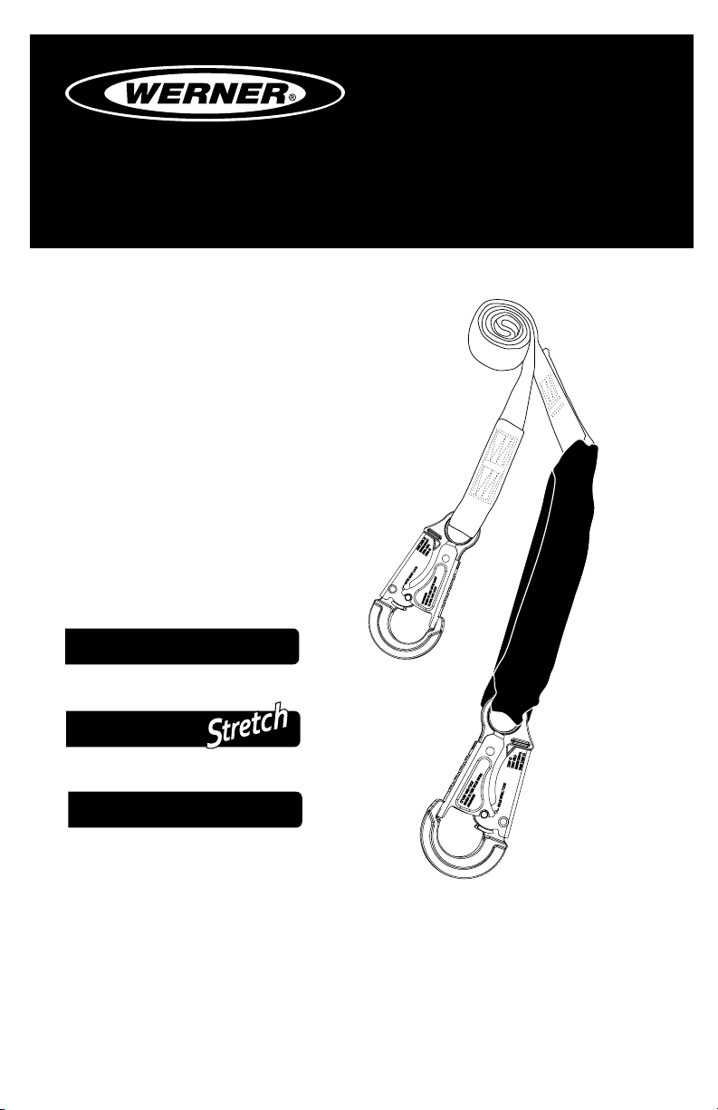
ENERGY ABSORBING LANYARDS
Complies with ANSI Z359, OSHA 1910
and 1926 regulations and requirements.
CUERDAS
ABSORBEDORAS
DE ENERGÍA
Cumplen con los requisitos y normas
ANSI Z359, OSHA 1910 y 1926.
TM
DeCoil
CUERDA ABSORBEDORA DE ENERGÍA
ARD
TM
DeCoil
ENERGY ABSORBING ELASTIC LANYARD
CUERDA ELÁSTICA ABSORBEDORA DE ENERGÍA
TM
SoftCoil
INTERNAL ENERGY ABSORBING LANYARD
CUERDA INTERNA ABSORBEDORA DE ENERGÍA
(This manual applies to all lanyards with model numbers starting C3 and C4)
Este manual aplica a todas las cuerdas con números de modelo que comienzan en C3 y C4)
Werner Co. Fall Protection 724-588-2000
93 Werner Rd. 888-523-3371 toll free/ llamada gratuita
Greenville, PA 16125 888-456-8458 fax
Page 2
CAUTION!
If use of fall protection equipment is necessary then the work
environment is dangerous and potentially deadly. Werner Co. products
are designed to eliminate as much of the hazard only as possible but
can do that ONLY if they are used correctly. Use this equipment as it
was designed to be used, after appropriate training, under the direct
supervision of a competent person, according to the instructions
provided, and in accordance with OSHA and local safety regulations.
User MUST read and understand all cautions and instructions. Failure
to heed these guidelines could result in injury or even death. WORK
SAFE! WORK SMART!
ENGLISH
Page 2
Page 3

ENERGY ABSORBING LANYARDS
USER INSTRUCTIONS
Contents
WARNINGS ...........................................................................................................4
I. BEFORE USING LANYARDS
a. Inspect .....................................................................................................................4
b. Compatibility ............................................................................................................6
c. Anchorage Strength .................................................................................................6
d. Clearances ................................................................................................................7
e. Rescue Plan..............................................................................................................7
f. Training .....................................................................................................................7
II. LANYARD DESCRIPTIONS
a. Fall Restraint or Positioning Lanyards ..................................................................7
b. Fall Arrest Lanyards ................................................................................................7
1. Werner Co. DeCoil Energy Absorbing Lanyard with DCELL Shock Pack ......8
2. Werner Co. DeCoil Stretch..................................................................................9
3. SoftCoil Internal Energy Absorbing Lanyard....................................................9
III.CONNECTIONS
a. Lanyard Use ...........................................................................................................10
b. Connecting to Harness .........................................................................................10
c. Connecting to an Anchorage ................................................................................10
d. Connecting a D-Ring Extender .............................................................................11
IV. USE WARNINGS, RESTRICTIONS AND CAUTIONS
a. Adequate anchorages ............................................................................................11
b. Fall Distance ..........................................................................................................11
c. Swing Fall ...............................................................................................................12
d. Capacity ..................................................................................................................12
e. Environmental Hazards ......................................................................................... 12
f. Components/Subsystems ..................................................................................... 13
g. Care and Storage ................................................................................................... 13
V. LABELS/IDENTIFICATION/INSPECTION RECORDS ................................... 13
VI. EQUIPMENT RECORDS ............................................................................... 17
VII. INSPECTION RECORD ................................................................................17
ENGLISH
Page 3
Page 4
Warning:
This product is just one part of a personal fall arrest, work positioning,
travel restraint, climbing or rescue system. It must be matched
correctly with other components to form a complete and functional
system. The user must understand the function of each of these
components and follow the manufacturer’s instructions for use for
each. ANSI and OSHA standards require that training in the use of
these products be provided by a competent person. The user must be
provided these instructions, should read and follow them, and then
consult the competent person who will supervise his work if he has
any questions about any part of the instructions. The employer must
provide training in the proper use, inspection, and maintenance of all
components in the system, and these instructions can be used as part
of that training. The equipment should be used ONLY in accordance
with these instructions, local ordinances and codes, the applicable
OSHA and ANSI standards, and the employer’s safety plan.
IF YOU HAVE ANY QUESTIONS ABOUT ANYTHING IN THESE
INSTRUCTIONS, THE EQUIPMENT, OR PROPER USE OF THE
EQUIPMENT, CONTACT WERNER CO. FOR MORE INFORMATION.
I. Before Using the Lanyard
Before using this equipment the user should take certain steps to
ensure that it is in good condition and safe for use. Some lanyards
are manufactured with an exclusive Werner WebAlert Inspectable
Webbing that is designed to make these inspections easier. The
WebAlert Webbing has a contrasting internal color that will make cuts
or abrasions more visible. Any appearance of the internal WebAlert
color indicates that product should receive further examination by
a competent person before continued use. If a competent person
determines that the affected webbing or component has lost strength
then that product should be immediately removed from service.
a. Inspect
ENGLISH
Page 4
Examine all equipment thoroughly, daily before use, and periodically
by a competent person who is not the user. Verify the condition of
each component. If any damage, abnormalities or excessive wear
are found, the lanyard should be removed from service.
Page 5
ENERGY ABSORBING LANYARDS
USER INSTRUCTIONS
1. First check the impact load indicators. For lanyards with DCELL
Shock Packs, the clear plastic cover permits full view. Check the
area near the INSPECT!™ tag to see if the shock absorbing web
is intact. If there is any indication of impact loading the lanyard
should be removed from service and destroyed. On SoftCoil
Lanyards, check the load indicating stitch near the INSPECT!
tag at the end of the lanyard for signs of deployment. Remove
from service any lanyard which exhibits indications of impact
loading.
2. Check the webbing for cuts, abrasions, burns, welding spatter,
or discoloration that could be caused by chemical exposure.
The WebAlert feature of the webbing on some models is
intended to make these much easier to spot. If any abnormality
is noted, check further by bending the webbing to expose the
irregularity to determine severity.
3. For cable legs, examine the entire length for any breaks or kinks
and the swaged ttings for any cracks or irregularities.
4. Check all stitching for any broken threads.
™
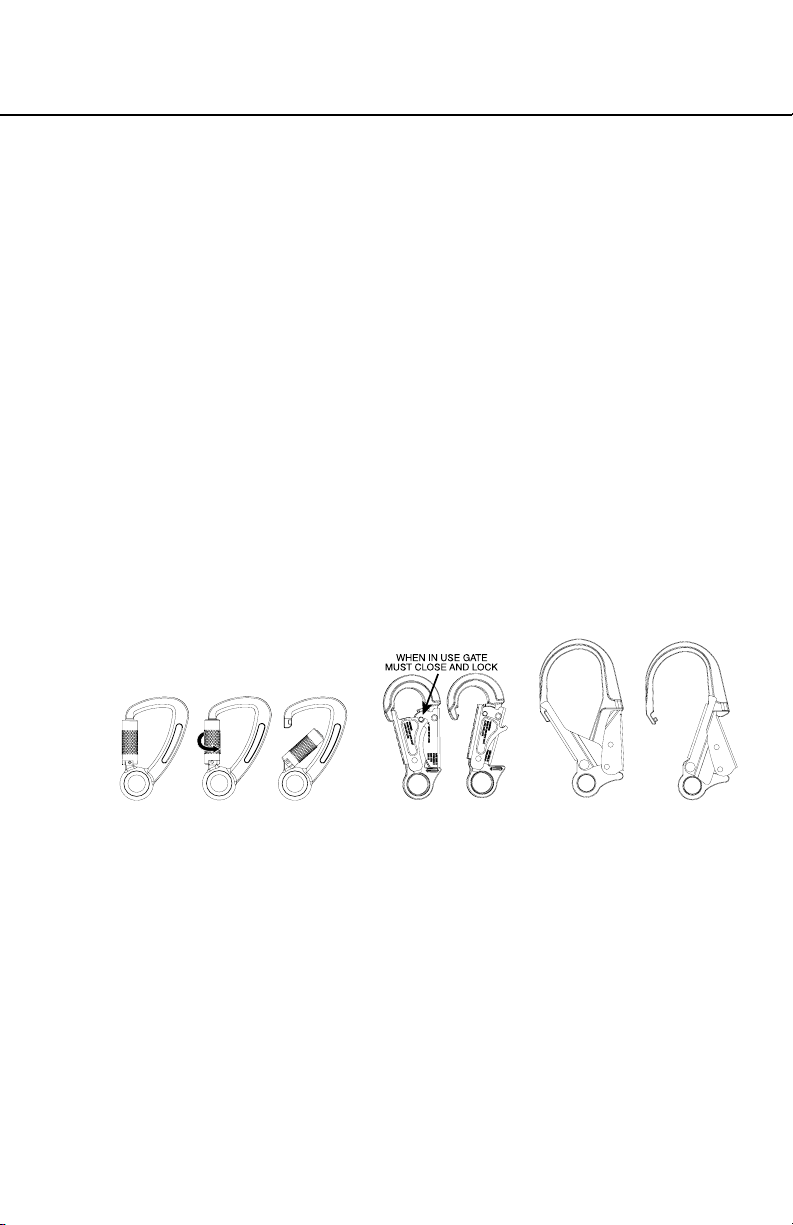
LOCKED UNLOCKEDTWIST
LOCKED UNLOCKED LOCKED UNLOCKED
5. Check all hardware for cracks, bends, irregularities, corrosion,
or sharp edges. Check the snap hook gates for proper smooth
operation. The gates must close and lock and the primary gate
must not open unless the locking gate is depressed. Ensure the
mechanism is undamaged and functioning properly.
6. Check all plastic parts for damage or cracks. If any abnormalities
are found, the product should be removed from service.
7. Verify that all labels are in place and legible. Examples of
the labels can be found in section IV of these instructions.
If abnormalities are found in any of these areas then the
competent person should be consulted to determine if that item
is safe for continued use or if it should be removed from service.
Page 5
ENGLISH
Page 6
Warning:
No alteration or modication of any fall protection equipment
is permitted for any reason unless authorized in writing by Werner Co.
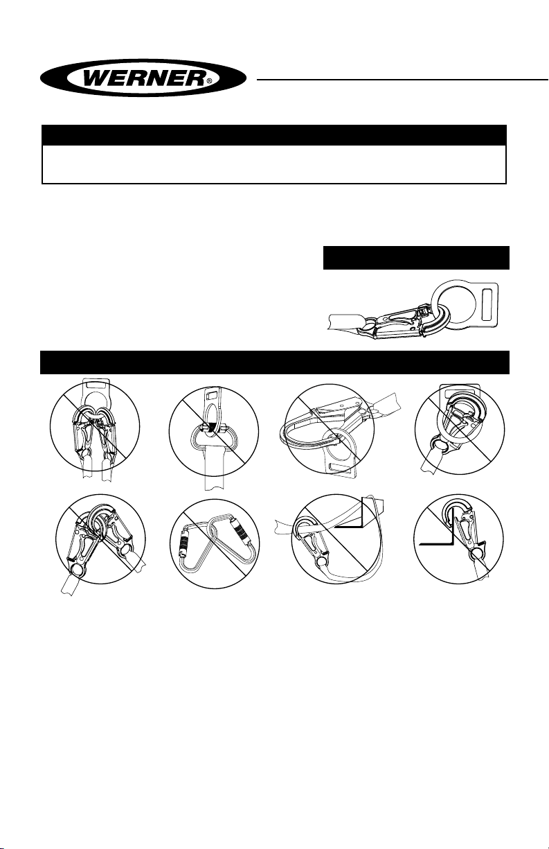
b. Compatibility.
Verify compatibility of all subsystems being used. Werner
products connected to Werner
products should be compatible, but
PROPER CONNECTIONS
connection to other products should
be veried for compatibility to ensure
there is no possibility of accidental
detachment from side-loading,
rollout, non-standard closures, etc.
INAPPROPRIATE CONNECTIONS
A. B.
NO! NO! NO! NO!
D. E. F.
C.
ENGLISH
Page 6
NO!NO!NO!NO!
c. Anchorage Strength
Verify that Chosen Anchorages are Appropriate.
1. For fall arrest, anchors need to have strength of either 5000 lbs.
per attached user (22.2kN), or be certied by a qualied person to
have strength of not less than 3600 lbs. per attached user (16kN).
2. For fall restraint (where there is no possibility of accidental
detachment), anchors need to withstand a static load of 3000
lbs per attached user (13.3kN), or be certied by a qualied
person to be able to withstand two times the foreseeable force.
Page 7

ENERGY ABSORBING LANYARDS
USER INSTRUCTIONS
3. For positioning systems, the anchorage strength must be a
minimum of 3000 lbs (13.3 kN), or be certied by a qualied
person to have strength of twice the foreseeable force.
4. For rescue systems, the anchorage should withstand a static
load of 3000 lbs (13.3kN) or be certied by a qualied person
for ve times the foreseeable load.
d. Clearance
Verify that adequate clearance exists below the work area, and
there are no objects or obstructions below the work area that the
user could contact in the case of a fall.
e. Rescue Plan
If a worker falls and is forced to remain suspended for any length of
time, physical damage to the body or even death can result. For this
reason Werner Co., OSHA, ANSI, CSA and most local regulations
require that a rescue plan and the means to implement the rescue
plan are in place before use of this equipment.
f. Training
OSHA, ANSI, and most local ordinances require that workers using
this product receive adequate training by a competent person
before use of this product. These instructions and their entire
contents should be a part of that training.
II. Lanyard Descriptions
Lanyards have a variety of attachment hardware types and types of
lanyard legs depending on their intended use. Use the lanyard type
that is appropriate for the work being done.
a. Fall Restraint or Positioning Lanyards
With no shock pack or other provision for energy absorption these
lanyards fall outside the dynamic performance requirements of
OSHA and ANSI standards for energy absorbing lanyards. Without
energy absorption, these lanyards are to be used only for
positioning/fall restraint either when there is no possibility of
a fall or to prevent workers from reaching a fall hazard.
1. Fixed lengths starting from 2 feet, depending on need.
2. Adjustable lengths starting from 2 feet, depending on need.
ENGLISH
Page 7
Page 8
b. Fall Arrest Lanyards
Fall arrest lanyards contain an energy absorbing element that will
absorb the energy of a fall reducing the fall’s impact on the user.
There are two energy absorber types. One consolidates the energy
absorber into one compact package, the Shock Pack. The other
type, the Werner SoftCoil™ lanyard with energy absorbing inner core
employs energy absorbing webbing the full length of the lanyard leg
inside tubular webbing. This entire lanyard stretches when there is
an impact so there is no separate Shock Pack. Both absorb energy
equally; the traditional shock pack has the advantage of enabling
use of different types of lanyard legs, while the SoftCoil™ type is
slightly more compact.
All Werner shock absorbing lanyards are designed for a maximum
free fall distance of 6 feet unless otherwise indicated on the product
labels. Every Werner lanyard can be had with a variety of different
connectors, according to the intended use. The different lanyard
types are:
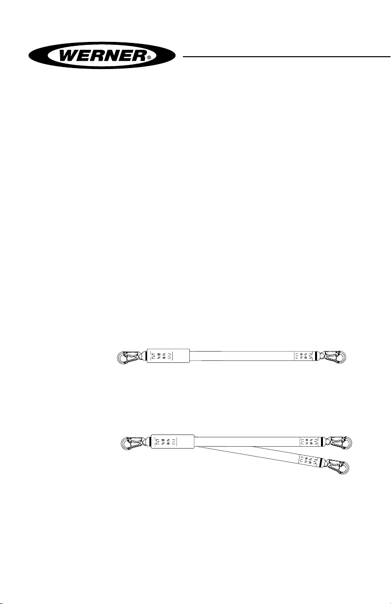
1. Werner DeCoil Energy Absorbing Lanyard with DCELL Shock
Pack
i. Single leg
Available with a variety of hook options. The hook, carabiner,
or loop on the shock pack end is always attached to the
harness’ dorsal (back) D-ring.
ENGLISH
Page 8
ii. Dual leg
Dual leg lanyards permit movement with 100 percent tie-off.
Available with a variety of hook options. Again always connect
to the dorsal (back) D-ring with the hook, carabiner, or loop at
the shock pack end of the lanyard.
Page 9
ENERGY ABSORBING LANYARDS
USER INSTRUCTIONS
iii. Web
WebAlert inspectable webbing with red internal bers or
elastic webbing
i. Standard length. 6 feet or 3 feet.
ii. Adjustable length with adjuster buckle added enabling
reduction in total lanyard length in situations of reduced
clearances.
iv. Cable
Cable is resistant to welding spatter, and vinyl coating
provides abrasion resistance and facilitates inspection of
damaged areas. Check for damage, kinks or broken strands.
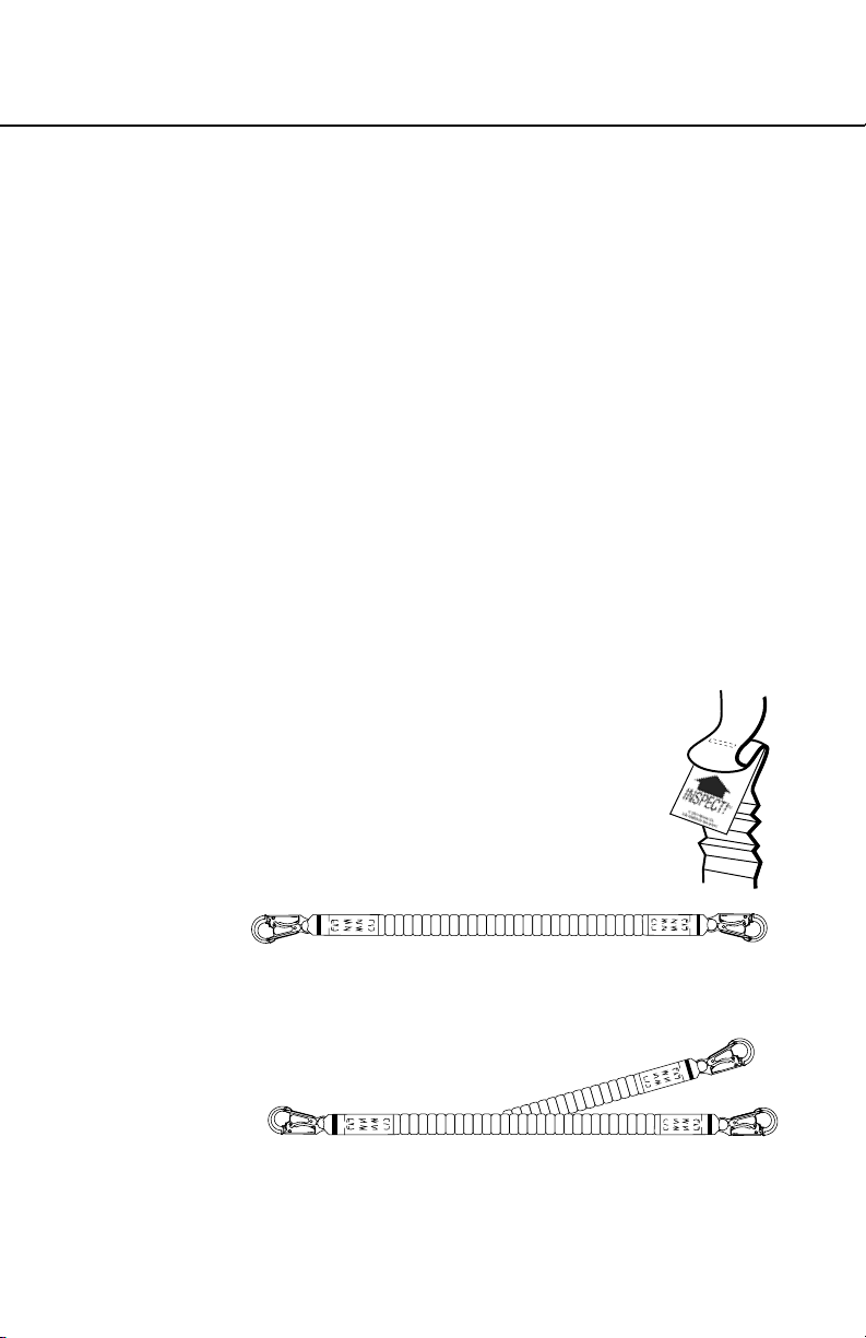
2. Werner DeCoil Stretch
An elastic lanyard is a convenient 4 foot length at rest, keeping
the dangling legs from becoming a trip hazard, then stretching
to the normal 6 foot length for movement.
3. SoftCoil Internal Energy Absorbing Lanyard
Energy absorbing lanyards with no shock
pack. The Werner SoftCoil™ lanyards include
an INSPECT!™ impact indicator stitch. If this
stitch has been deployed the product should be
removed from Service. None of the “SoftCoil™”
lanyards are appropriate for tie-back use. Instead
use the appropriate DeCoil Tie-Back lanyard.
i. Single leg with a variety of hook options. The standard sized
hook, carabiner, or loop on the label end is always attached
to the harness’ dorsal (back) D-ring.
ii. Dual leg lanyards permit movement with 100 percent tie-
off. Available with a variety of hook options. Again always
connect to the dorsal (back) D-ring with the standard sized
hook, carabiner, or loop at the label end of the lanyard.
Page 9
ENGLISH
Page 10
III. Connections
a. Lanyard Use
Connect the shock pack end of the lanyard (or the label end of
the no-shock-pack SoftCoil lanyards) ONLY to the harness’ back
D-ring, NEVER to any other connection.
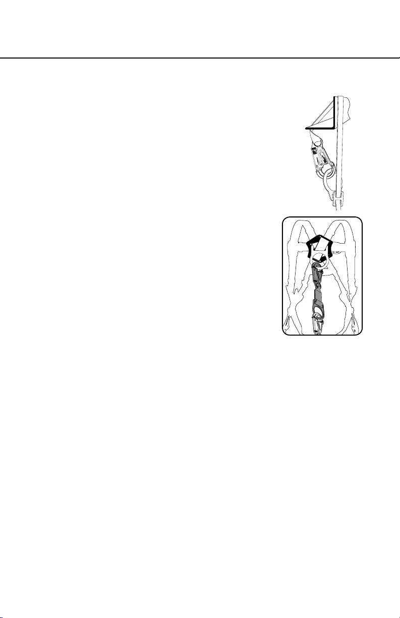
b. Connecting to Harness
1. Connect the lanyard to the rear D-ring for general fall arrest.
The shock pack end of a DeCoil lanyard, or the end of a
SoftCoil lanyard with labels should be attached to the harness
rear D-ring. With twin leg lanyards, the center hook should be
attached to the harness.
2. To connect a lanyard with a web loop, pass the web loop through
the harness rear D-ring. Insert the other end of the lanyard
through the web loop. Pull the lanyard all the way through the
web loop to tighten on the harness D-ring in a chocking fashion.
1
ENGLISH
Page 10
2
c. Connecting to an Anchorage
1. Connect the opposite end of the lanyard to an anchor or anchor
connector ensuring the connection is made with compatible
components.
2. For twin leg lanyards, connect one of the free ends to an anchor
or anchor connector. With one leg still attached, the user can
move to a new location to attach the second lanyard leg to a
different anchor and then disconnect the rst leg.
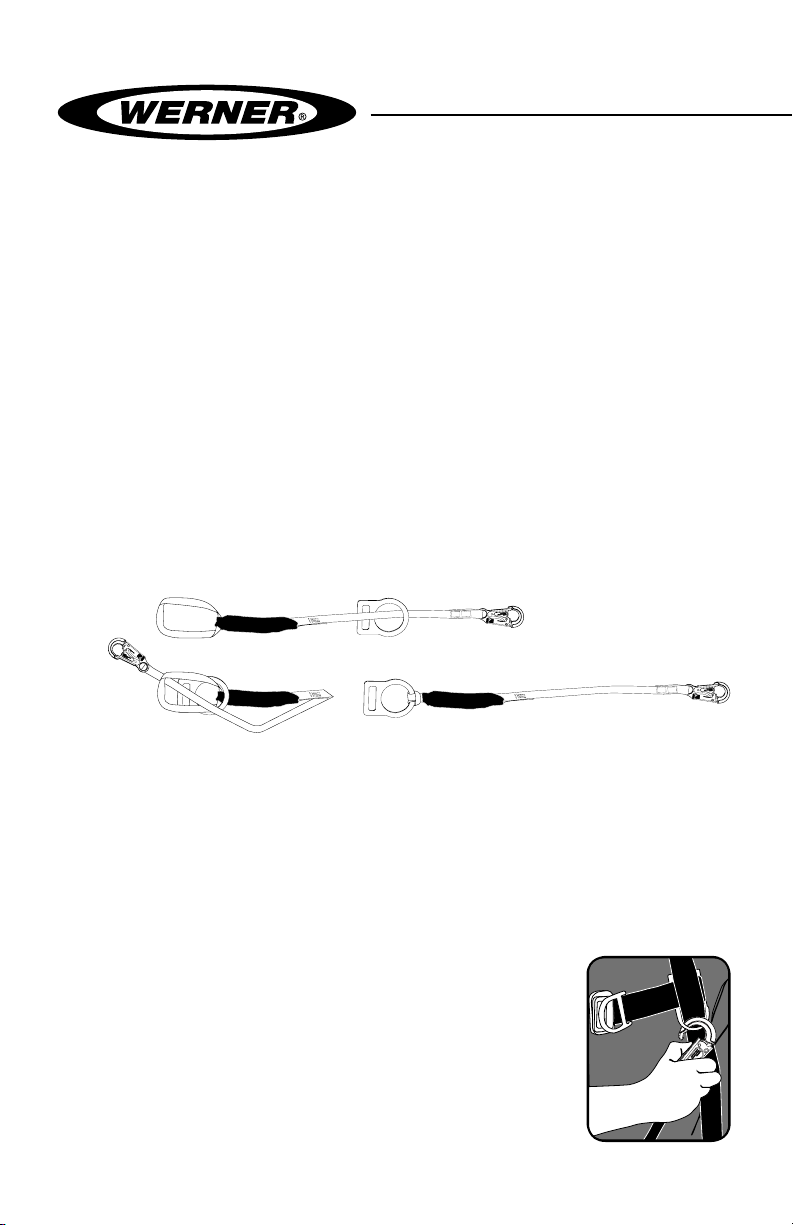
3. When not in use the lanyard leg should be
“parked” on the wearer’s chest lanyard keeper,
never to a permanently xed component on
the harness (hip D-ring, chest D-ring, etc.).
4. For Tie-Back lanyards with a oating D-ring,
do not wrap around sharp edges or where an
edge could contact the gate of the carabiner or
snap hook. The end of the lanyard opposite the
3
Page 11
ENERGY ABSORBING LANYARDS
USER INSTRUCTIONS
harness connection may be wrapped around
a connection point capable of supporting the
necessary anchor load of 5000 lbs. or twice
the maximum expected load as certied by
a qualied person. Tie-back should only be
done with lanyards specically designed for
this purpose. Do not attempt this connection
with standard lanyards. The connecting hook
must be attached to the oating D-ring and not
directly to the lanyard webbing or cable.
d. Connecting a D-Ring Extension
The D-Ring Extension is simply a separate
webbing extension with a snap hook or loop on
one end and a D-ring or O-ring on the other
and is connected between the harness back
D-ring and the lanyard being used as shown.
IV. Use Warnings, Restrictions and Cautions
a. Adequate Anchorages
OSHA requires anchor strengths of 5000 lbs or twice the maximum
expected load if the anchorage has been certied by a qualied
person. Use of any anchorage that is of inadequate strength could
result in injury or death.
b. Fall Distance
Contact with a lower level can occur even when this equipment is in
perfect operating condition if there is any object in the path of a fall
or if the height of the anchorage being used is inadequate. The fall
distance can vary according to the connecting subsystem used. The
following diagrams indicate typical clearance calculations for shock
absorbing lanyards and self-retracting lifelines. While these are
typical situations, the authorized/competent person on site should
make these determinations for each work situation depending on
ENGLISH
Page 11
Page 12

the site-specic conditions.
Total Fall
Distance
(Free Fall +
Deceleration)
Free Fall
Working Level
Lower Level or Obstruction
Energy
Absorbing
Lanyard
Length of Anchorage Connector
6 ft.
Length of Lanyard
11 ft.
4 ft.
Deceleration Free Fall Distance
2 ft.
Safety Factor
1 ft. Harness Stretch
5 ft.
To Worker’s Back D-Ring
Total Estimated
Fall Distance
18 ft.
Fall distance for shock absorbing lanyards
c. Swing Falls
Ensure that there will be
no possibility of a swing-fall
impact. Swing falls occur when
the user is not directly below
the anchorage, so if he falls his
swing could produce an impact
with an object.
CorrectIncorrect
d. Capacity
Anchorages
SWING FALL
HAZARD
ENGLISH
Page 12
Maximum capacity for all Werner lanyards is 310 lbs (140.6 kg) for
the combined weight of a worker and all tools. For any weight over
310 lbs (140.6 kg) contact Werner Co. for more information. The
employer should ensure that all other elements of the fall protection
system are adequate to support any higher weights.
e. Environmental Hazards
This equipment is used only under the direct supervision of a
competent person who is able to identify hazards that must be
avoided including electrical and chemicals, machinery or other
moving objects, sharp edges, damaged anchorages or structures,
Page 13

ENERGY ABSORBING LANYARDS
USER INSTRUCTIONS
or any other workplace element that could damage this equipment
or prevent it from operating as intended.
f. Components/Subsystems
Before rst use, a qualied person should inspect and determine that
all components and subsystems are compatible and will perform
correctly when combined into a complete personal fall protection
system. Consult the information in these instructions, and if any
additional information is needed contact Werner Co. directly.
g. Care and Storage
Product can be cleaned using a mild laundry detergent in warm or
cold water and air dried. Store in a cool, dry place, protected from
exposure to any direct light.
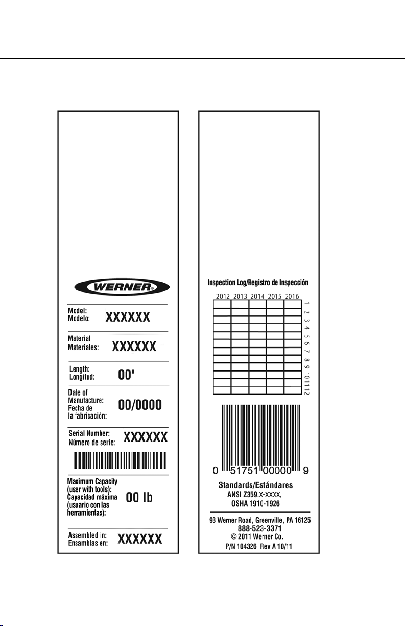
V. Labels/Identication/Inspection Records
a. All products should be inspected by the user thoroughly before
each use. Additional inspections by a competent person other than
the user should be conducted at intervals of no less than one year.
That interval should be shortened any time the product is used in a
harsh environment or is exposed to conditions such as chemicals,
abrasion, heat or any other factor that could affect the strength of
any of the materials or components.
b. The lanyard labels provide an inspection grid to record these
inspections by a competent person. Use a punch or permanent
marker to record those dates.
c. This manual should always accompany the product or be on le with
the employer for access when needed. Record the identication
details for the lanyard and record the inspections in the inspection
log. It is important to keep this log current, complete, and available
as needed.
Page 13
ENGLISH
Page 14

Shock pack
ENGLISH
Indicator label
Page 14
Inspect label
Page 15
ENERGY ABSORBING LANYARDS
USER INSTRUCTIONS
front back
Id label
ENGLISH
Page 15
Page 16

ENGLISH
Page 16
front back
Warning label front / back
Page 17

ENERGY ABSORBING LANYARDS
USER INSTRUCTIONS
VI. Equipment Record
PART NUMBER
SERIAL NUMBER
DATE
MANUFACTURED
PURCHASE DATE
ASSIGNED TO
SPECIFICATIONS
Werner Co. LANYARDS
Certied to meet ANSI Z359, OSHA 1910 and 1926 standards and
regulations for the lanyard component of a complete personal fall
arrest system.
Individually bar coded model and serial numbers, location and date of
manufacture are on product label.
VII. Inspection Record
INSPECTION RECORD
DAT E INSPECTOR PASS/FAIL
DAT E INSPECTOR PASS/FAIL
Page 17
ENGLISH
Page 18

NOTES
Page 19

CUERDAS ABSORBEDORAS DE ENERGÍA
INSTRUCCIONES PARA EL USUARIO
¡PRECAUCIÓN!
Si el uso de equipos de protección contra caídas es necesario, entonces el
ambiente de trabajo es peligroso y potencialmente mortal. Los productos
Werner Co. están diseñados para eliminar peligros tanto como sea posible
pero SÓLO si estos productos se utilizan correctamente. Utilice este equipo
ya que éste fue diseñado para usarse, utilice este equipo después de una
capacitación apropiada, bajo la supervisión directa de una persona calicada,
de acuerdo con las instrucciones suministradas, y de acuerdo con las
regulaciones OSHA y las regulaciones de seguridad locales. El usuario DEBE
leer y entender todas las precauciones e instrucciones. No tener en cuenta
estas directrices podría resultar en lesiones o incluso la muerte. ¡TRABAJE
DE MANERA SEGURA! ¡TRABAJE DE MANERA INTELIGENTE!
Página 2
ESPAÑOL
Page 20

Contenido
ADVERTENCIAS .........................................................................................................4
I. ANTES DE UTILIZAR LAS CUERDAS
a. Inspeccione ......................................................................................................................... 4
b. Compatibilidad .................................................................................................................... 6
c. Resistencia del anclaje ....................................................................................................... 6
d. Alturas libres........................................................................................................................7
e. Plan de rescate .................................................................................................................... 7
f. Capacitación ........................................................................................................................ 7
II. DESCRIPCIONES DE LAS CUERDAS
a. Cuerdas para el evitamiento de caídas o cuerdas de posicionamiento ........................ 7
b. Cuerdas de detención de caídas ....................................................................................... 7
1. Cuerda absorbedora de energía DeCoil de Werner Co. con
2. Cuerda elástica absorbedora de energía Stretch DeCoil de Werner Co. ............. 9
3. Cuerda interna absorbedora de energía SoftCoil9 ................................................ 9
III. CONEXIONES
a. Uso de la cuerda ................................................................................................................ 10
b. Conexión con un arnés ..................................................................................................... 10
c. Conexión con un anclaje .................................................................................................. 10
d. Conexión de una extensión para anillo en “D” ................................................................11
IV. TENGA EN CUENTA LAS ADVERTENCIAS, RESTRICCIONES
Y PRECAUCIONES
a. Anclajes adecuados ...........................................................................................................11
b. Distancia de caída .............................................................................................................11
c. Caída tipo columpio .......................................................................................................... 12
d. Capacidad .......................................................................................................................... 12
e. Peligros ambientales ........................................................................................................ 12
f. Componentes/Subsistemas ............................................................................................. 12
g. Cuidado y almacenamiento .............................................................................................. 13
Paquete contra Impacto DCELL .............................................................................. 8
V. ETIQUETAS/IDENTIFICACIÓN/REGISTROS DE INSPECCIÓN ..........................13
VI. REGISTROS DE EQUIPOS .................................................................................. 17
VII. REGISTRO DE INSPECCIÓN ............................................................................. 17
ESPAÑOL
Página 3
Page 21

CUERDAS ABSORBEDORAS DE ENERGÍA
INSTRUCCIONES PARA EL USUARIO
Advertencia:
Este producto es sólo una parte de un sistema personal de detención de caídas,
posicionamiento para el trabajo, limitación de recorrido, ascenso o rescate. Éste
debe combinarse correctamente con otros componentes para conformar un
sistema completo y funcional. El usuario debe entender la función de cada uno
de estos componentes y seguir las instrucciones del fabricante para el uso de
cada componente. Las normas ANSI y OSHA exigen que una persona calicada
suministre capacitación sobre el uso de estos productos. El usuario debe recibir
estas instrucciones, debe leerlas y seguirlas, y luego debe consultar a la persona
calicada que supervisará su trabajo si tiene alguna pregunta acerca de cualquier
parte de las instrucciones. El empleador debe proporcionar capacitación sobre
el uso apropiado, inspección y mantenimiento de todos los componentes del
sistema, y estas instrucciones pueden utilizarse como parte de esa capacitación.
El equipo SÓLO debe utilizarse de acuerdo con estas instrucciones, ordenanzas
y códigos locales, las normas OSHA y ANSI aplicables, y el plan de seguridad del
empleador.
SI USTED TIENE ALGUNA PREGUNTA ACERCA DE ALGO DE ESTAS INSTRUCCIONES,
EL EQUIPO O EL USO APROPIADO DEL EQUIPO, COMUNÍQUESE CON WERNER
CO. PARA OBTENER MÁS INFORMACIÓN.
I. Antes de utilizar la cuerda
Antes de utilizar este equipo, el usuario debe realizar cier tos pasos para garantizar
que éste está en buenas condiciones y es seguro para su uso. Algunas cuerdas
se fabrican con Correa Tejida Inspeccionable WebAlert exclusiva de Werner Co.
que está diseñada para facilitar estas inspecciones. La correa tejida WebAlert
tiene un color interno contrastante que hará más visibles las cortaduras o
desgastes. La aparición del color interno de la WebAlert indica que el producto
debe recibir una inspección adicional por parte de una persona calicada antes
de continuar su uso. Si la persona calicada determina que el componente o
correa tejida afectada ha perdido resistencia, entonces ese producto debe
retirarse inmediatamente del servicio.
a. Inspeccione
Examine completamente todo el equipo, diariamente antes del uso, y
periódicamente por parte de una persona calicada que no sea el usuario.
Verique la condición de cada componente. Si se encuentra cualquier daño,
anormalidad o desgaste excesivo, la cuerda debe retirarse del servicio.
ESPAÑOL
Página 4
Page 22

1. Primero revise los indicadores de carga de impacto. Para las cuerdas con
paquetes contra impacto DCELL, la cubierta plástica transparente permite
visión total. Revise el área cerca de la etiqueta INSPECT!™ para ver si la
correa tejida absorbedora de impacto está intacta. Si hay alguna indicación
de carga de impacto, la cuerda debe retirarse del servicio y destruirse. En
las cuerdas SoftCoil, revise la costura indicadora de carga cerca de la
etiqueta INSPECT!™ en el extremo de la cuerda, en busca de indicios de
despliegue. Retire del servicio cualquier cuerda que muestre indicios de
carga de impacto.
2. Revise las correas tejidas en busca de cortaduras, abrasión, quemaduras,
salpicadura de soldadura, o decoloración que pudiera haberse causado
por exposición a productos químicos. La característica WebAlert de
las correas tejidas, en algunos modelos, está diseñada para facilitar la
detección de estos daños. Si se observa cualquier anormalidad, revise
adicionalmente doblando la correa tejida para exponer la irregularidad y
determinar la gravedad de la anormalidad.
3. Para los tramos de cuerda/cable, examine toda la longitud en busca de
cualquier rotura o retorcimientos y examine los acoples forjados en busca
de cualquier grieta o irregularidad.
4. Revise toda la costura en busca de hilos rotos.
CUANDO ESTÁ EN USO,
EL CIERRE DEBE QUEDAR
CERRADO Y ASEGURADO
ESPAÑOL
Página 5
LOCKED UNLOCKEDTWIST
ASEGURADO GIRE DESASEGURADO ASEGURADO DESASEGURADO ASEGURADO DESASEGURADO
LOCKED UNLOCKED LOCKED UNLOCKED
5. Revise todos los herrajes en busca de grietas, dobladuras, irregularidades,
corrosión o bordes losos. Revise los ganchos de cierre resortado para
vericar el funcionamiento sin problemas. Los cierres deben cerrar y
asegurar, y el cierre principal no debe abrir a menos que se presione
el cierre asegurable. Verique que el mecanismo no tiene daños y está
funcionando apropiadamente.
6. Revise todas las piezas plásticas en cuanto a daños o grietas. Si se
encuentra cualquier anormalidad, el producto debe retirarse del servicio.
7. Verique que todas las etiquetas están en su sitio y son legibles. Pueden
encontrarse ejemplos de etiquetas en la sección IV de estas instrucciones.
Si se encuentran anormalidades en alguna de estas áreas, entonces debe
consultarse a la persona capacitada para que determine si ese elemento
es seguro para continuar su uso o si debe retirarse del servicio.
Page 23

CUERDAS ABSORBEDORAS DE ENERGÍA
INSTRUCCIONES PARA EL USUARIO
Advertencia:
No se permite ninguna alteración ni modicación de ningún equipo de protección
contra caídas, por ningún motivo, a menos que sea autorizado por escrito por
Werner Co.
b. Compatibilidad
Verique la compatibilidad de todos los
subsistemas que se están utilizando.
Los productos Werner conectados con
productos Werner son compatibles, pero
la conexión con otros productos debe
vericarse en cuanto a compatibilidad
para garantizar que no hay posibilidad de
desconexión accidental por carga lateral,
rodaje, cierres no-estándares, etc.
CONEXIONES INAPROPIADAS
A. B.
CONEXIONES APROPIADAS
C.
NO! NO! NO! NO!
D. E. F.
c. Resistencia del anclaje
Verique que los anclajes elegidos son apropiados.
1. Para la detención de caídas, los anclajes deben tener una resistencia de
5000 lbs por cada usuario conectado (22.2kN), o ser certicados por una
persona calicada indicando que tienen una resistencia no inferior a 3600 lbs.
por cada usuario conectado (16kN).
2. Para el evitamiento de caídas (donde no hay posibilidad de desconexión
accidental), los anclajes deben soportar una carga estática de 3000 lbs
por cada usuario conectado (13.3kN), o ser certicados por una persona
calicada para poder soportar dos veces la fuerza previsible.
NO!NO!NO!NO!
ESPAÑOL
Página 6
Page 24

3. Para los sistemas de puesta en posición, la resistencia de los anclajes
debe ser de 3000 lbs (13.3 kN) como mínimo, o ser certicados por una
persona calicada indicando que tienen una resistencia de dos veces la
fuerza previsible.
4. Para los sistemas de rescate, los anclajes deben soportar una carga
estática de 3000 lbs (13.3kN) o ser certicados por una persona calicada
para cinco veces la carga previsible.
d. Altura libre
Verique que existe una altura libre adecuada debajo del área de trabajo, y que
no hay objetos ni obstrucciones debajo del área trabajo que el usuario pudiera
contactar en caso de una caída.
e. Plan de rescate
Si un trabajador cae y queda obligado a permanecer suspendido durante
cualquier período de tiempo, podría producirse daño físico o incluso la muerte.
Por este motivo, Werner Co., las regulaciones de OSHA, ANSI, CSA, y la
mayoría de las regulaciones locales exigen la existencia de un plan de rescate
y los medios para ejecutar un plan de rescate, antes del uso de este equipo.
f. Capacitación
Las regulaciones OSHA, ANSI, y la mayoría de las regulaciones locales exigen
que los trabajadores que utilizan este producto reciban capacitación adecuada
por parte de una persona calicada, antes del uso de este producto. Estas
instrucciones y su contenido completo deben ser parte de esa capacitación.
II. Descripciones de las cuerdas
Las cuerdas tienen una variedad de tipos de herrajes de conexión y tipos de
tramos de cuerda dependiendo de su uso pretendido. Utilice el tipo de cuerda
que sea apropiado para el trabajo que se realizará.
a. Cuerdas para el evitamiento de caídas o cuerdas de posicionamiento
Sin ningún elemento contra choque ni otro mecanismo para la absorción de
energía, estas cuerdas no quedan incluidas en los requisitos de desempeño
dinámico de las normas OSHA y ANSI para las cuerdas absorbedoras de
energía. Sin absorción de energía, estas cuerdas sólo deben utilizarse
para posicionamiento/evitamiento de caídas, ya sea cuando no hay
posibilidad de caída o para evitar que los trabajadores lleguen a tener un
peligro de caída.
1. Longitudes jas que comienzan desde 0.61 m (2 pies), dependiendo de la
necesidad.
2. Longitudes ajustables que comienzan desde 0.61 m (2 pies), dependiendo
ESPAÑOL
de la necesidad.
Página 7
Page 25

CUERDAS ABSORBEDORAS DE ENERGÍA
INSTRUCCIONES PARA EL USUARIO
b. Cuerdas de detención de caídas
Las cuerdas de detención de caídas contienen un elemento absorbedor de
energía que absorberá la energía de una caída reduciendo el impacto de la
caída para el usuario. Hay dos tipos de absorbedores de energía. Un (1) tipo
de absorbedor unica el absorbedor de energía en un (1) paquete compacto,
el Paquete contra Impacto (Shock Pack). El otro tipo, la cuerda SoftCoil™
de Werner con núcleo interior absorbedor de energía emplea correa tejida
absorbedora de energía a todo lo largo del tramo de cuerda dentro de la correa
tejida tubular. Toda esta cuerda se estira cuando hay un impacto, de modo que
no hay Paquete contra Impacto separado. Ambas absorben la energía de igual
manera; el paquete contra impacto tradicional tiene la ventaja de hacer posible
el uso de diferentes tipos de tramos de cuerda, mientras que el tipo SoftCoil™
es levemente más compacto.
Todas las cuerdas absorbedoras de impacto Werner están diseñadas para una
distancia de caída libre máxima de 0.61 m (6 pies) a menos que se indique
algo distinto en las etiquetas del producto. Cada cuerda Werner puede tenerse
con una variedad de conectores diferentes, de acuerdo con el uso pretendido.
Los diferentes tipos de cuerdas son:
1. Cuerda absorbedora de energía DeCoil de Werner con Paquete contra
Impacto DCELL
i. Tramo sencillo
Disponible con una variedad de opciones de gancho. El gancho, argolla
metálica, o lazo en el extremo con paquete contra impacto siempre se
sujeta al anillo en “D" dorsal (espalda) del arnés.
ii. Tramo doble
Las cuerdas de tramo doble permiten movimiento con amarre del 100%.
Disponible con una variedad de opciones de gancho. Nuevamente,
siempre conecte al anillo en “D” dorsal (espalda) mediante el gancho,
argolla metálica, o lazo ubicado en el extremo con paquete contra
impacto de la cuerda.
Página 8
ESPAÑOL
Page 26

iii. Correa tejida
Correa tejida inspeccionable WebAlert con bras internas rojas o
correa tejida elástica.
i. Longitud estándar. 1.83 m y 0.91 m (6 pies y 3 pies).
ii. Longitud ajustable con hebilla ajustadora adicional que
hace posible la reducción de la longitud total de la cuerda en
situaciones con alturas libres reducidas.
iv. Cable
El cable es resistente a la salpicadura de soldadura, y el recubrimiento
de vinilo proporciona resistencia a la abrasión y facilita la inspección de
áreas dañadas. Revise en busca de daño, retorcimientos o hilos rotos.
2. Cuerda elástica absorbedora de energía Stretch DeCoil de Werner
Cuerda elástica con una conveniente longitud de 1.2 m (4 pies) en
reposo, evitando que los tramos colgantes se conviertan en un riesgo de
tropezón, luego alargándose hasta una longitud normal de 1.83 m (6 pies)
para movimiento.
3. Cuerda interna absorbedora de energía SoftCoil
Cuerdas absorbedoras de energía sin paquete contra impacto. Las
cuerdas SoftCoil de Werner incluyen una abrazadera
indicadora de impacto INSPECT!™. Las cuerdas
SoftCoil™ de Werner incluyen una costura indicadora de
impacto INSPECT!™. Si esta costura se ha desplegado,
el producto debe retirarse del servicio. Ninguna de las
cuerdas “SoftCoil™” es apropiada para uso como amarre
con sí misma (es decir, no es apropiada para colocar
alrededor de un elemento de soporte, por ejemplo una
barra, para luego enganchar con sí misma). En su lugar,
utilice la cuerda de amarre Tie-Back DeCoil apropiada.
ESPAÑOL
Página 9
i. Tramo sencillo con una variedad de opciones de gancho. El gancho de
tamaño estándar, argolla metálica, o lazo en el extremo con etiqueta
siempre se sujeta al anillo en “D" dorsal (espalda) del arnés.
ii. Las cuerdas de tramo doble permiten movimiento con amarre del 100%.
Disponible con una variedad de opciones de gancho. Nuevamente,
siempre conecte al anillo en “D” dorsal (espalda) mediante el gancho
de tamaño estándar, argolla metálica, o lazo en el extremo con etiqueta
de la cuerda.
Page 27

CUERDAS ABSORBEDORAS DE ENERGÍA
INSTRUCCIONES PARA EL USUARIO
III. Conexiones
a. Uso de la cuerda
Conecte el extremo con paquete contra impacto de la cuerda (o el extremo con
etiqueta de las cuerdas SoftCoil sin paquete contra impacto) SÓLO al anillo en
“D” de espalda del arnés, NUNCA a ninguna otra conexión.
b. Conexión con un arnés
1. Conecte la cuerda al anillo en “D” trasero para detención de caída general.
El extremo con paquete contra impacto de una cuerda DeCoil, o el
extremo de una cuerda SoftCoil con etiquetas debe sujetarse al anillo en
“D” trasero del arnés. Con las cuerdas de tramo doble, el gancho central
debe conectarse al arnés.
2. Para conectar una cuerda con un lazo de correa tejida, pase el lazo de
correa tejida a través del anillo en “D” trasero del arnés. Inserte el otro
extremo de la cuerda a través del lazo de correa tejida. Hale la cuerda todo
el recorrido a través del lazo de correa tejida para apretar sobre el anillo
en “D” del arnés de manera estrangulante.
1
2
c. Conexión con un anclaje
1. Conecte el extremo opuesto de la cuerda a un anclaje o conector de anclaje
vericando que la conexión se realice con componentes compatibles.
2. Para las cuerdas de tramo doble, conecte uno de los extremos libres a un
anclaje o conector de anclaje. Con un tramo todavía conectado, el usuario
puede moverse hacia un nuevo lugar para conectar el segundo tramo de
la cuerda a un anclaje diferente y luego desconectar el primer tramo.
3. Cuando no esté en uso, el tramo de la cuerda debe
“estacionarse” en la abrazadera de la cuerda de
pecho del usuario, nunca en un componente jo
permanente del arnés (anillo en “D” de cadera, anillo
en “D” de pecho, etc.).
4. Para las cuerdas de amarre Tie-Back con un anillo
en “D” otante, no envuelva alrededor de bordes
losos o donde un borde pudiera hacer contacto
con el cierre de una argolla metálica o gancho de
cierre resortado. El extremo de la cuerda opuesto a
la conexión del arnés puede enrollarse alrededor de un punto de conexión
capaz de soportar la carga de anclaje necesaria de 5000 lbs. o dos veces
3
Página 10
ESPAÑOL
Page 28

la carga esperada máxima según lo certicado por una
persona calicada. El amarre sólo debe realizarse con
cuerdas diseñadas especícamente para este propósito.
No intente esta conexión con cuerdas estándares. El
gancho conector debe sujetarse al anillo en “D” otante y
no directamente al cable o correa tejida de la cuerda.
d. Conexión de una extensión para anillo en “D”
La extensión para anillo en “D” es simplemente
una extensión de correa tejida separada con un
gancho de cierre resortado o lazo en un extremo
y un anillo en “D” o anillo en “O” en el otro extremo,
y se conecta entre el anillo en “D” de espalda del
arnés y la cuerda que se está utilizando según
se muestra.
IV. Tenga en cuenta las advertencias, restricciones y
precauciones
a. Anclajes adecuados
OSHA exige resistencias de anclaje de 5000 lbs, o dos veces la carga
esperada máxima si el anclaje ha sido certicado por una persona calicada.
El uso de algún anclaje que tenga una resistencia inadecuada podría resultar
en lesiones o la muerte.
b. Distancia de caída
Aún cuando este equipo esté en perfectas condiciones de funcionamiento
podría ocurrir contacto con un nivel inferior si hay algún objeto en la trayectoria
de lDistancia de caída para las cuerdas absorbedoras de impactotancia de
caída puede variar de acuerdo con el subsistema conectivo utilizado. Los
siguientes diagramas indican los cálculos de espacio libre típico para cuerdas
absorbedoras de impacto y cuerdas salvavidas auto-retráctiles. Aunque
éstas son situaciones típicas, la persona autorizada/calicada en sitio debe
realizar estas decisiones para cada situación de trabajo dependiendo de las
condiciones especícas del sitio.
ESPAÑOL
Página 11
Page 29

CUERDAS ABSORBEDORAS DE ENERGÍA
Total Fall
Distance
(Free Fall +
Deceleration)
Free Fall
Working Level
Lower Level or Obstruction
Energy
Absorbing
Lanyard
Length of Anchorage Connector
6 ft.
Length of Lanyard
11 ft.
4 ft.
Deceleration Free Fall Distance
2 ft.
Safety Factor
1 ft. Harness Stretch
5 ft.
To Worker’s Back D-Ring
Total Estimated
Fall Distance
18 ft.
INSTRUCCIONES PARA EL USUARIO
Distancia de caída para las cuerdas absorbedoras de impacto
Cuerda
Caída libre
absorbedora
de energía
Nivel de trabajo
Obstrucción o nivel inferior
Longitud del conector del anclaje
1.83 m (6 pies)
Longitud de la cuerda
1.22 m (4 pies)
Distancia de caída libre con
desaceleración
0.31 m (1 pie) de alargamiento del arnés
1.5 m (5 pies)
Al anillo en “D” de espalda del
trabajador
0.61 m (2 pies)
Factor de seguridad
Distancia de
caída total
(Caída libre +
Desaceleración)
3.35 m (11 pies)
Distancia de caída
estimada total
5.5 m (18 pies)
c. Caídas tipo columpio
Verique que no existe la posibilidad
de un impacto por caída tipo
Anclajes
Anchorages
columpio. Las caídas tipo columpio
ocurren cuando el usuario no está
directamente debajo del anclaje,
de modo que si el usuario cae, su
balanceo podría producir un impacto
con un objeto.
d. Capacidad
CorrectIncorrect
Correcto Incorrecto
La capacidad máxima para todas las cuerdas Werner es 310 lbs (140.6 kg)
para el peso combinado de un trabajador y todas las herramientas. Para
cualquier peso superior a 310 lbs (140.6 kg), comuníquese con Werner Co.
para obtener más información. El empleador debe garantizar que todos los
otros elementos del sistema de protección contra caídas son apropiados para
soportar cualquier peso superior.
e. Peligros ambientales
Este equipo sólo debe utilizarse bajo la supervisión directa de una persona
calicada que pueda identicar los peligros que deben evitarse, incluyendo la
electricidad y productos químicos, maquinaria y otros objetos en movimiento,
bordes losos, estructuras o anclajes dañados, o cualquier otro elemento en
el sitio de trabajo que pudiera dañar este equipo o evitar su funcionamiento
según lo previsto.
f. Componentes/Subsistemas
Antes del primer uso, una persona calicada debe inspeccionar y decidir que
todos los componentes y subsistemas son compatibles y que funcionarán
correctamente en combinación con un sistema personal completo de protección
SWING FALL
PELIGRO DE CAÍDA
HAZARD
TIPO COLUMPIO
Página 12
ESPAÑOL
Page 30

contra caídas. Consulte la información en estas instrucciones, y si se requiere
cualquier información adicional, comuníquese directamente con Werner Co.
g. Cuidado y almacenamiento
El producto puede limpiarse utilizando un detergente suave para lavado de
ropa, en agua tibia o fría y secarse al aire. Guarde en un lugar fresco y seco
protegido de la exposición a cualquier luz directa.
V. Etiquetas/Identicación/Registros de inspección
a. Todos los productos deben ser inspeccionados completamente por el usuario
antes de cada uso. Una persona calicada, diferente al usuario, debe realizar
inspecciones adicionales en intervalos no inferiores a un (1) año. Ese intervalo
debe acortarse cada vez que el producto se utiliza en un ambiente agresivo
o se expone a condiciones tales como productos químicos, abrasión, calor o
cualquier otro factor que pudiera afectar la resistencia de cualquiera de los
materiales o componentes.
b. Las etiquetas de las cuerdas proporcionan una tabla de inspección para
registrar estas inspecciones por parte una persona calicada. Utilice un punzón
o marcador permanente para registrar estos datos.
c. Este manual siempre debe acompañar el producto o estar en los archivos
del empleador para consultarlo cuando se requiera. Registre los detalles de
identicación del arnés y registre las inspecciones en el registro de inspección.
Es importante mantener este registro actualizado, completo y disponible según
se requiera.
ESPAÑOL
Página 13
Page 31

CUERDAS ABSORBEDORAS DE ENERGÍA
INSTRUCCIONES PARA EL USUARIO
Etiqueta de inspección
Paquete contra impacto
Etiqueta indicadora
ESPAÑOL
Página 14
Page 32

ESPAÑOL
Página 15
parte delantera
Etiqueta de identicación
parte trasera
Page 33

CUERDAS ABSORBEDORAS DE ENERGÍA
INSTRUCCIONES PARA EL USUARIO
parte delantera
parte trasera
Parte delantera / trasera de etiqueta de
advertencia
ESPAÑOL
Página 16
Page 34

VI. Registro de equipos
NÚMERO DE
PIEZA
NÚMERO DE SERIE
FECHA DE FABRI-
CACIÓN
FECHA DE COMPRA
ASIGNADO A
ESPECIFICACIONES
CUERDAS Werner Co.
Certicadas para cumplir las regulaciones y normas ANSI Z359, OSHA
1910 y 1926 para los componentes de cuerdas de sistemas personales
completos de detención de caídas.
Los números de modelo y números de serie, sitio y fecha de fabricación,
con código de barras individual, están en la etiqueta del producto.
VII. Registro de inspección
REGISTRO DE INSPECCIÓN
FECHA INSPECTOR APROBADO/
NO-APROBADO
FECHA INSPECTOR APROBADO/
NO-APROBADO
ESPAÑOL
Página 17
Page 35

CUERDAS ABSORBEDORAS DE ENERGÍA
INSTRUCCIONES PARA EL USUARIO
NOTA S
ESPAÑOL
Page 36

93 Werner Rd. Greenville, PA 16125
724-588-2000 • 888-523-3371 toll free • 888-456-8458 fax
PN103766-01 RevC ©2012 Werner Co. 2/12
Werner Fall Protection
 Loading...