

Page 1
FALL PROTECTION
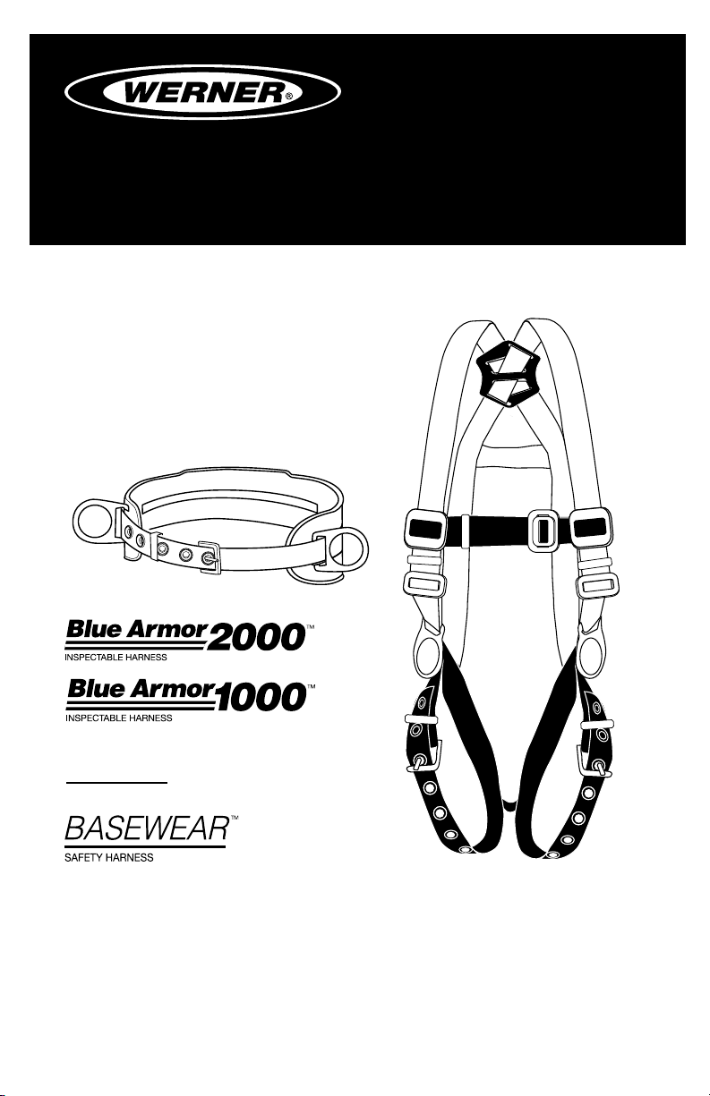
LITEFIT
TM
PROTECCIÓN CONTRA CAÍDAS
USER INSTRUCTIONS
INSTRUCCIONES PARA EL USUARIO
HARNESSES AND BELTS
Complies with ANSI Z359.1-2007, OSHA 1910 and 1926 requirements.
ARNESES Y
CORREAS
Cumple con las normas ANSI
Z359.1-2007, OSHA 1910 y 1926.
SAFETY HARNESS
(This manual applies to all harnesses with model numbers starting with H1,
H2, H3, and H4 and belts with model numbers starting with M11 and M21.)
(Este manual aplica a todos los arneses con números de modelo que comienzan con
H1, H2, H3 y H4 correas con números de modelo que comienzan con M11 y M21).
Werner Fall Protection 724-588-2000
93 Werner Rd. 888-523-3371 toll free/ llamada gratuita
Greenville, PA 16125 888-456-8458 fax
Page 2
CAUTION!
If use of fall protection equipment is necessary then the work
environment is dangerous and potentially deadly. Werner Company
products are designed to eliminate as much of the hazard as possible
but can do that ONLY if they are used correctly. Use this equipment as
it was designed to be used, after appropriate training, under the direct
supervision of a competent person, according to the instructions
provided, and in accordance with OSHA and local safety regulations.
User MUST read and understand all cautions and instructions. Failure
to heed these guidelines could result in injury or even death. Please,
WORK SAFE! WORK SMART!
ENGLISH
Page 2
Page 3

HARNESSES AND BELTS
USER INSTRUCTIONS
Contents
I. BEFORE USING THE HARNESS ...................................................................... 4
a. Inspect ......................................................................................................................4
b. Compatibility ............................................................................................................5
c. Fall Protection Plan ..................................................................................................6
d. Training .....................................................................................................................8
II. HARNESS AND BELT DESCRIPTIONS ..........................................................8
a. Harness Types ..........................................................................................................8
III. HARNESS ADJUSTMENT AND USE .............................................................. 9
a. Adjustment ..............................................................................................................9
b. Making Connections..............................................................................................11
c. Anchorage Strength ...............................................................................................14
d. Care and storage....................................................................................................14
IV. USE WARNINGS, RESTRICTIONS AND CAUTIONS
a. Purpose ..................................................................................................................15
b. Capacity ..................................................................................................................15
c. Limitations ..............................................................................................................16
V. LABELS/IDENTIFICATION/INSPECTION RECORDS ................................... 18
VI. EQUIPMENT RECORDS ............................................................................... 20
VII. INSPECTION RECORDS .............................................................................20
ENGLISH
Page 3
Page 4
Warning:
This product is just one part of a personal fall arrest, work positioning,
travel restraint, climbing or rescue system. It must be matched
correctly with other components to form a complete and functional
system. The user must understand the function of each of these
components and follow the manufacturer’s instructions for use for
each. ANSI and OSHA standards require that training in the use of
these products be provided by a competent person. The user must be
provided these instructions, should read and follow them, and then
consult the competent person who will supervise his work if he has
any questions about any part of the instructions. The employer must
provide training in the proper use, inspection, and maintenance of all
components in the system, and these instructions can be used as part
of that training. The equipment should be used ONLY in accordance
with these instructions, local ordinances and codes, the applicable
OSHA and ANSI standards, and the employer’s safety plan. Alterations
or misuse of this product, or failure to follow instructions may result
in serious injury or death.
IF YOU HAVE ANY QUESTIONS ABOUT ANYTHING IN THESE
INSTRUCTIONS, THE EQUIPMENT, OR PROPER USE OF THE
EQUIPMENT, CONTACT WERNER CO. FOR MORE INFORMATION.
I. Before Using the Harness
Before using this equipment the user should take certain steps to
ensure that it is in good condition and safe for use. Some Werner
harnesses are manufactured with an exclusive WebAlert Inspectable
Webbing that is designed to make these inspections more accurate
and thorough. The WebAlert Webbing has a contrasting internal
color that will indicate any cut or abraded section. Any appearance
of the internal WebAlert color indicates that product should receive
further examination by the competent person before continued use.
If the competent person determines that the affected webbing or
component has lost strength then that product should be immediately
removed from service.
a. Inspect
ENGLISH
Page 4
Examine all equipment thoroughly, daily before use, and periodically
by a competent person who is not the user. Verify the condition of
Page 5

HARNESSES AND BELTS
USER INSTRUCTIONS
each component. If any damage, abnormalities or excessive wear
are found, the harness should be removed from service.
1. Check the impact load indicators on the back of the harness
below the D-ring. If the INSPECT!™ tag is intact, check the
stitching above the tag. If any threads are broken the harness
could have been subjected to an impact load.
2. Inspect the webbing for cuts, frayed ends, abrasion, burns,
welding spatter, or discoloration that could be caused by
chemical exposure. Found on some Werner harnesses, the
WebAlert feature is intended to make these much easier to spot.
3. Check all stitching for any broken threads.
4. Inspect all hardware for cracks, bends, loose parts, irregularities,
corrosion, or sharp edges.
5. Check every grommet, for dents, cracks, or especially
displacement. Any damage here could indicate impact loading
of the harness.
6. Check all plastic pads for damage or cracks. If any abnormalities
are found the product should be removed from service.
7. Verify that all labels are in place and legible. Examples of the
labels can be found in section IV of these instructions.
8. Record the inspection date and results in the inspection log on
page 20.
9. If abnormalities are found in any of these areas then the
competent person should be consulted to determine if that item
is safe for continued use or if it should be removed from service.
IMPORTANT: If the Werner harness has been subjected to a fall
arrest or impact load, it must be immediately removed from service.
IMPORTANT: Do not attempt to make any self-repairs or alterations to
the product. If any doubt about safety of the equipment, remove it
from service.
b. Compatibility
Werner equipment is designed for use with Werner approved
components and subsystems only. Substitutions or replacements
made with non-approved components or subsystems may
jeopardize compatibility of equipment and may affect the safety and
reliability of the complete system.
Page 5
ENGLISH
Page 6

Connectors are considered to be compatible with connecting
elements when they have been designed to work together in
such a way that their sizes and shapes do not cause their gate
mechanisms to inadvertently open regardless of how they become
oriented. Contact Werner Co. if you have any questions about
compatibility. Connectors (hooks, carabiners, and D-rings) must be
capable of supporting at least 5,000 lbs. (22.2kN). Connectors must
be compatible with the anchorage or other system components.
Do not use equipment that is not compatible. Non-compatible
connectors may unintentionally disengage. Connectors must be
compatible in size, shape, and strength. Self locking snap hooks
and carabiners are required by ANSI Z359 and OSHA.
c. Fall Protection Plan
Plan your fall arrest or restraint system before starting your work.
Take into consideration all factors affecting your safety at any
time during use. The following list gives some important points to
consider when planning your system:
1. ANCHORAGE: Select a rigid anchorage point that is
capable of supporting the required loads. See section III.c.
The anchorage location must be carefully selected to reduce
possible free fall and swing fall hazards and to avoid striking an
object during a fall. For restraint systems the anchorage must be
located such that no vertical free fall is possible. For fall arrest
systems OSHA requires the anchorage be independent of the
means suspending or supporting the user.
2. FREE FALL: Do not work above the anchorage level, increased
fall distance will result. Personal fall arrest systems must be
rigged such that the potential free fall is never greater than 6 ft.
(1.83 m). Restraint systems must be rigged such that there is no
possible vertical free fall.
3. FALL ARREST FORCES: The assembled fall arrest system must
keep fall arrest forces below 1,800 lbs. (8 kN) when used with a
full body harness.
NOTE: Do not use a body belt for fall arrest.
ENGLISH
Page 6
Page 7
HARNESSES AND BELTS
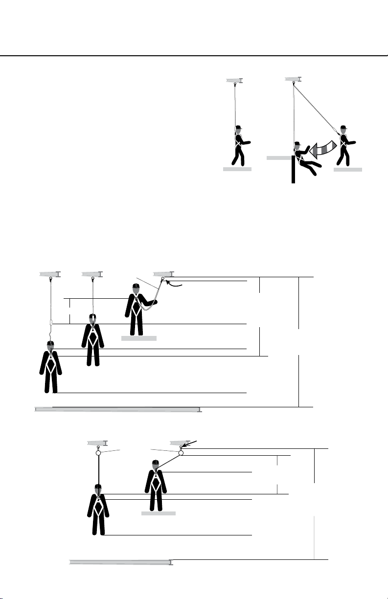
Total Fall
Distance
(Free Fall +
Deceleration)
Free Fall
Working Level
Lower Level or Obstruction
Energy
Absorbing
Lanyard
Length of Anchorage Connector
6 ft. (1.83 m)
Length of Lanyard
1/2 ft. (0.15 m)
Anchorage Stretch
11 ft. (3.4 m)
4 ft. (1.2 m)
Deceleration Free Fall Distance
2 ft. (0.6 m)
Safety Factor
1 ft. (0.31 m) Harness Stretch
5 ft. (1.5 m)
To Worker’s Back D-Ring
Total Estimated
Fall Distance
18.5 ft. (5.6 m)
1/2 ft. (0.15 m)
4. SWING FALLS: Swing falls
occur when the anchor is not
directly above the point where a
fall occurs. The force of striking
an object while swinging can be
great and cause serious injury.
Minimize swing falls by working
as directly below the anchorage
as possible.
5. FALL CLEARANCE: Make certain enough clearance exists
in your fall path to prevent striking an object. The amount of
clearance needed is dependent upon the type of connecting
subsystem used and anchorage location.
Fall distance for shock absorbing lanyards
USER INSTRUCTIONS
SWING FALL
HAZARD
Anchorages
CorrectIncorrect
Fall distance for self-retracting lifeline
Anchorage Stretch
Bottom of Retractable Lifeline
2 ft. (0.6 m)
Maximum Free Fall
2.5 ft. (0.8 m)
Maximum Deceleration
1 ft. (0.31 m) Harness Stretch
5 ft. (1.5 m)
To Worker’s Back D-Ring
2 ft. (0.6 m)
Safety Factor
Lower Level or Obstruction
Self Retracting
Lifeline
Working Level
Maximum Arrest
Distance (per ANSI)
4.5 ft. (1.4 m)
Total Estimated
Fall Distance
13 ft. (3.96 m)
Page 7
ENGLISH
Page 8
6. SHARP EDGES: Avoid working where parts of the system will
be in contact with, or abrade against, unprotected sharp edges.
7. RESCUE: Should a fall occur, the user (employer) must have a
rescue plan. If a worker falls and is forced to remain suspended
for any length of time, physical damage to the body or even
death can result. For this reason Werner, OSHA, ANSI and
most local regulations require that a rescue plan and the means
to implement the rescue plan are in place before use of this
equipment.
8. AFTER A FALL: Any equipment which has been subjected
to the force of arresting a fall must be removed from service
immediately.
d. Training
OSHA, ANSI, and most local ordinances require that workers using
this product receive adequate training before use of this product.
These instructions and their entire contents should be a part of that
training.
II. Harness and Belt Descriptions
a. Harness Types
Harnesses have a variety of attachment points, depending on their
intended use. Use the harness type that is appropriate for the work
being done.
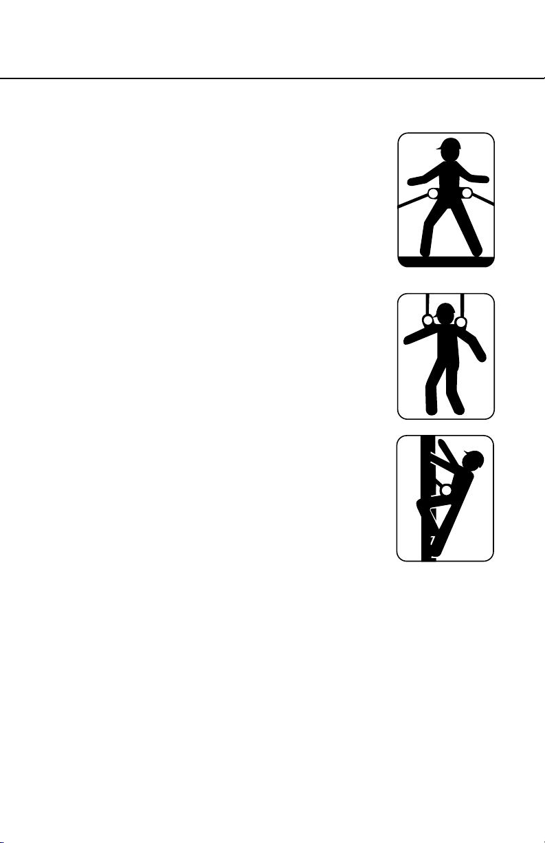
1. Fall Arrest
The dorsal or back D-ring is the only
attachment point authorized for general fall
protection use, and can also be used for a
fall restraint connection. The position of the
dorsal attachment ensures that if a worker
falls, his body will rst be oriented into a feetdownward position, permitting the sub-pelvic
strap to absorb most of the energy of the fall. It
is the ONLY attachment permitted for general
fall arrest.
2. Work Positioning
Hip D-rings are for work positioning only, generally with a
ENGLISH
Page 8
rebar chain assembly. Hip D-rings are NEVER for fall arrest.
Body belts with hip D-rings can be used for positioning, but
Page 9
HARNESSES AND BELTS
USER INSTRUCTIONS
cannot be used for fall arrest. Body belts for
positioning are often used in conjunction with
full body harnesses with dorsal D-rings for
supplementary fall arrest protection. The use
of such a combination system is necessary
because a personal positioning system is
not designed for fall arrest purposes. By
using this combination system, the fall arrest
components will be activated should the
worker suffer a fall while working or changing
work positions.
3. Personnel Support/Retrieval
Shoulder D-rings. Used ONLY for personnel
support and retrieval, generally with a harness
spreader below a davit or tripod, and NEVER
for fall arrest.
4. Ladder Climbing
Chest D-ring for vertical lifelines and ladders,
connection to a rope or cable grab. Can
be used as a fall arrest attachment ONLY
when the attachment limits possible free-fall
distance to 18 inches (0.46 m) or less, and
limits the maximum arrest force to 900 lbs
(4kN) or less.
III. Harness adjustment and use
a. Adjustment
Harness closures and keepers ensure proper harness t, which is of
fundamental importance for safe use. Chest straps should t across
the middle of the sternum, not higher or lower. Leg straps should
be snug. Adjusting the leg straps too loosely will cause injuries in
the case of a fall. Correct harness adjustments will place the subpelvic strap snugly below the buttocks, the position necessary both
to absorb energy in the case of a fall, but also to provide some
relief from suspension trauma after a fall has occurred. Correct subpelvic position is the result of the correct combination of all the
harness adjustments.
ENGLISH
Page 9
Page 10

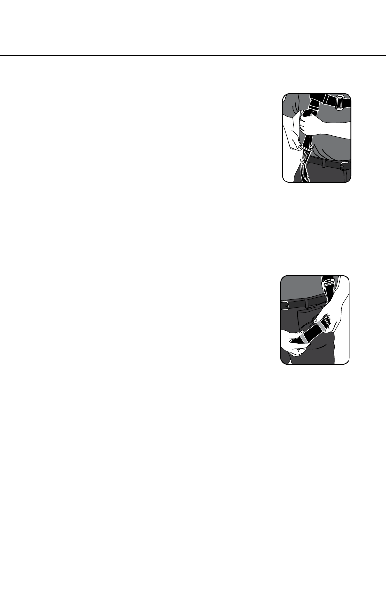
1. Tongue Buckle
i. The most common leg closure type with
function similar to the belt holding your
pants. Ensure that straps are not twisted.
ii. Put open end of strap with grommets
through the buckle, pull until snug on leg
and engage the tongue into a grommet.
iii. User MUST ensure that webbing ends
are tucked into the web keepers to keep this type of buckle
connected while in use. Failure to properly secure the leg
strap ends in the keepers could result in unintentional
disengagement.
2. Mating/Pass-Through Buckle
i. Ensure straps are not twisted and the
loose end is on the outside.
ii. Pass the buckle with the center bar
through the open buckle. The slot will
assist. Tug to ensure buckle is in place.
iii. Pull the webbing to tighten the strap so
there is a snug t.
iv. User MUST slide plastic keepers to strap end or nd other
location to tuck end to ensure there are no loose and
dangling ends.
3. Quick Connect
i. Ensure straps are not twisted and the
loose webbing end is on outside.
ENGLISH
Page 10
ii. Pull webbing through adjuster to loosen or
tighten until snug.
iii. Insert male connector into buckle, tug
straps to verify rmly engaged.
iv. User MUST slide plastic keepers to strap
end or nd other location to tuck end to
ensure there are no loose and dangling ends.
Page 11
HARNESSES AND BELTS
USER INSTRUCTIONS
4. Torso Length Adjuster
i. The torso adjuster ensures the overall t
of the harness. Check to see that the subpelvic strap is situated below the buttocks.
If it is too high the torso adjuster should
be loosened to lower the sub-pelvic strap.
If it is too low the torso adjuster can be
tightened to raise the sub-pelvic strap.
ii. To shorten or lengthen the torso webbing
push the top of the torso adjuster down so it is horizontal.
iii. Pull up either the inside web to lengthen, or pull up the
outside web to shorten the torso length.
For BaseWear harnesses, separate the small mating buckle
from the larger pass-through to allow web to ow through
the torso adjustment.
iv. When at the right length, slide the lower
plastic keeper down near the torso
adjuster and the upper plastic keeper up
so the webbing end is not dangling.
5. Webbing Keepers
All webbing ends are equipped with plastic
webbing keepers, which are important to the
safe use of the harness. Sliding one keeper close to the buckles
ensures the buckle can’t be accidently opened or moved while
in use. Sliding the other close to the end of the strap keeps if
from being loose and dangling and a possible snag hazard.
6. Joining belts to harnesses
Some Werner harnesses made without integrated belts have
loops through which accessory belts can be looped, joining the
accessory to the harness. The loops are found on the inside of
the harness webbing, below the impact indicators.
b. Making Connections
1. Only use self-locking snap hooks and carabiners with this
equipment. Only use connectors that are suitable to each
application. Ensure all connections are compatible in size, shape
and strength. Do not use equipment that is not compatible.
Ensure all connectors are fully closed and locked.
Page 11
ENGLISH
Page 12
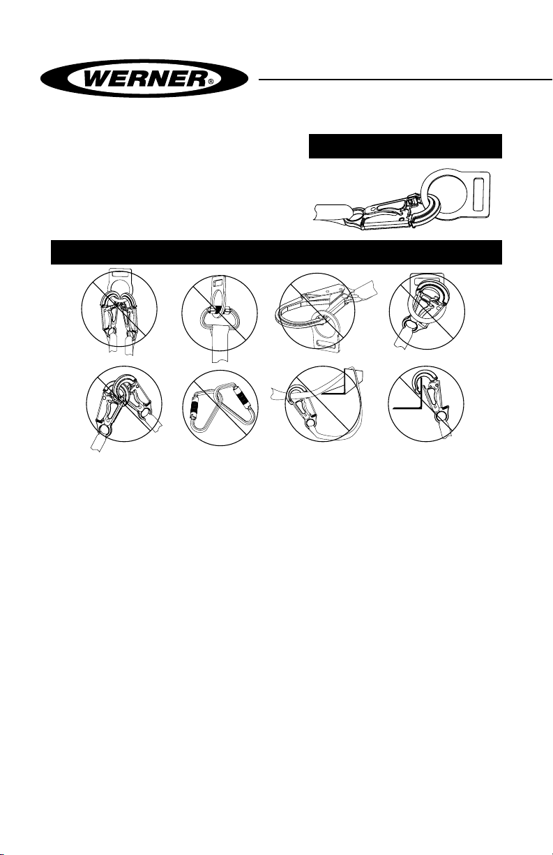
2. Werner Co. connectors (snap
hooks and carabiners) are
designed to be used only as
specied in each product’s
instructions. See below for
inappropriate connections.
INAPPROPRIATE CONNECTIONS
NO! NO! NO! NO!
Werner Co. snap hooks and carabiners should NOT be connected:
i. to a D-ring to which another connector is attached.
ii. in a manner that would result in a load on the gate. If the
connecting element that a snap hook or carabiner attaches
to is undersized or irregular in shape, a situation could occur
where the connecting element applies a force to the gate of
the snap hook or carabiner. This force may cause the gate
(of either a self-locking or a non-locking snap hook) to open,
allowing the snap hook or carabiner to disengage from the
connecting point.
NOTE: Large throat snap hooks should not be connected to
standard size D-rings or similar objects which will result in a load
on the gate if the hook or D-ring twists or rotates. Large throat
snap hooks are designed for use on xed structural elements
such as rebar or cross members that are not shaped in a way
that can capture the gate of the hook.
iii. in a false engagement, where features that protrude from
the snap hook or carabiner catch on the anchor and without
ENGLISH
visual conrmation seems to be fully engaged to the anchor
point.
Page 12
PROPER CONNECTION
NO!NO!NO!NO!
Page 13

HARNESSES AND BELTS
USER INSTRUCTIONS
iv. to each other.
v. directly to webbing or rope lanyard or tie-back (unless
the manufacturer’s instructions for both the lanyard and
connector specically allow such a connection).
vi. to any object which is shaped or dimensioned such that the
snap hook or carabiner will not close and lock, or that rollout
could occur.
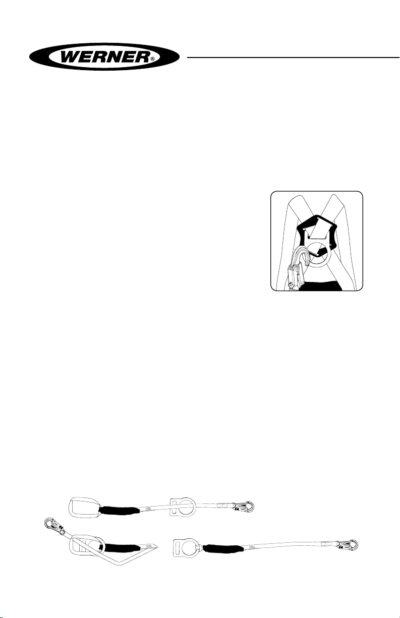
3. Proper use of D-rings
i. For fall arrest applications, connect
to the dorsal D-ring located between
the shoulders on the back of the full
body harness. Front D-rings may be
used for fall arrest only in applications
where the personal fall arrest system
limits the maximum free fall distance
to 2 ft. (0.6m) and limits the maximum
arrest force to 900 lbs. (4kN).]
ii. For restraint applications, the dorsal or frontal harness
attachment may be used.
If using a body belt for restraint applications, connect to the
D-ring opposite the restraining load.
iii. For positioning applications, the frontal or side D-rings may
be used.
iv. Shoulder D-rings are for retrieval only.
4. The pack end of a shock pack energy absorbing lanyard or the
designated end of an internal shock absorbing lanyard should
be attached to the harness rear D-ring. With twin leg lanyards,
the center hook should be attached to the harness.
5. To connect a lanyard with a web loop, pass the web loop through
the harness rear D-ring. Insert the other end of the lanyard
through the web loop. Pull the lanyard all the way through the
web loop to tighten on the harness D-ring in a choking fashion.
1
2
3
Page 13
ENGLISH
Page 14

c. Anchorage Strength
The anchorage strength required is dependent on the application.
Following are anchorage strength requirements for specic
applications:
1. FALL ARREST: Anchorages selected for personal fall arrest
systems (PFAS) shall have a strength capable of sustaining
static loads, applied in the directions permitted by the PFAS, of
at least; (A) 3,600 lbs. (16kN) when certication exists (see ANSI
Z359.1 for certication denition), or (B) 5,000 lbs. (22kN) in the
absence of certication. When more than one PFAS is attached
to an anchorage, the anchorage strengths set forth in (A) and
(B) above shall be multiplied by the number of personal fall
arrest systems attached to the anchorage. Per OSHA 1926.500
and 1910.66, anchorages used for attachment of PFAS shall
be independent of any anchorage being used to support or
suspend platforms, and capable of supporting at least 5,000 lbs.
(22kN) per user attached, or be designed, installed, and used as
part of a complete PFAS which maintains a safety factory of at
least two, and is supervised by a qualied person.
2. RESTRAINT: The anchorage must sustain static loads applied in
the directions permitted by the restraint system of at least 3,000
lbs. (13.3 kN) When more than one restraint system is attached
to an anchorage, the strengths stated above must be multiplied
by the number of restraint systems attached to the anchorage.
Warning:
Restraint anchorages may only be used where there is no possible
vertical free fall. Restraint anchorages do not have sufficient strength
for fall arrest. Do not connect personal fall arrest systems to restraint
anchorages.
3. WORK POSITIONING: The anchorage must sustain static loads
applied in the directions permitted by the work positioning
system of at least 3,000 lbs. (13.3 kN), or twice the potential
impact load, whichever is greater. When more than one work
positioning system is attached to an anchorage, the strengths
stated above must be multiplied by the number of restraint
systems attached to the anchorage.
d. Care and Storage
ENGLISH
Product can be spot cleaned using a mild, bleach-free laundry
Page 14
Page 15

HARNESSES AND BELTS
USER INSTRUCTIONS
detergent in warm or cold water and air or machine dried at
the lowest heat level. Store in a cool, dry place protected from
exposure to any direct light.
IV. Use Warnings, Restrictions and Cautions
a. Purpose
Werner full body harnesses and body belts are to be used as
components in personal fall arrest, restraint, work positioning,
climbing, or rescue systems. Harnesses and belts included in this
manual meet ANSI Z359.1 and OSHA requirements.
1. PERSONAL FALL ARREST: The full body harness is used as a
component of a personal fall arrest system. Personal fall arrest
systems typically include a full body harness and a connecting
subsystem (energy absorbing lanyard). Maximum arresting
force must not exceed 1,800 lbs (8kN).
2. RESTRAINT: The full body harness is used as a component of a
restraint system to prevent the user from reaching a fall hazard.
Restraint systems typically include a full body harness and a
lanyard or restraint line.
3. WORK POSITIONING: The full body harness is used as a
component of a work positioning system to support the user at
a work position. Work positioning systems typically include a full
body harness, positioning lanyard, and a back-up personal fall
arrest system.
4. CLIMBING: The full body harness is used as a component of a
climbing system to prevent the user from falling when climbing
a ladder or other climbing structure. Climbing systems typically
include a full body harness, vertical cable or rail attached to the
structure, and climbing sleeve.
5. RETRIEVAL: The full body harness is used as a component of a
retrieval system. Retrival systems are congured depending on
the type of retrieval.
b. Capacity
Maximum capacity of Blue Armor 1000 and 2000 harnesses is 400
lbs. (181.8 kg) and 310 lbs. (140.6 kg) for all other series.
Page 15
ENGLISH
Page 16

c. Limitations
ENGLISH
The following application limitations must be recognized and
considered before using this product:
1. FREE FALL: Restraint systems must be rigged such that there
is no possible vertical free fall. Personal fall arrest systems must
be rigged in such a way to limit the free fall to 6 ft. (1.83 m) (ANSI
Z359.1). Work positioning systems must be rigged so that free
fall is limited to 2 ft. (0.6 m) or less. Climbing systems must be
rigged so that free fall is limited to 1.5 ft. (0.46 m) or less. See
associated connecting subsystem manufacturer’s instructions
for further information.
2. FALL CLEARANCE: Make certain that enough clearance exists
in your fall path to prevent striking an object. The amount of
clearance required is dependent upon the type of connecting
subsystem used (lanyard, lifeline), the anchorage location, and
the amount of stretch in the lifeline.
3. EXTENDED SUSPENSION: A full body harness is not intended
for use in extended suspension applications.
4. CORROSION: Do not leave this equipment for long periods in
environments where corrosion of metal parts could take place as
a result of vapors from organic materials. Sewage and fertilizer
plants, for example, have high concentrations of ammonia. Use
near seawater or other corrosive environments may require more
frequent inspections or servicing to ensure corrosion damage is
not affecting the performance of the product.
5. CHEMICAL HAZARDS: Solutions containing acids, alkali, or
other caustic chemicals, especially at elevated temperatures,
may cause damage to this equipment. When working with
such chemicals, frequent inspection of this equipment must be
performed. Consult Werner Co. if doubt exists concerning using
this equipment around chemical hazards.
6. HEAT: This equipment is not designed for use in high temperature
environments. Protection should be provided for this equipment
when used near welding, metal cutting, or similar activities. Hot
sparks may burn or damage this equipment. Consult Werner Co.
for details on high temperature environments.
7. ELECTRICAL HAZARDS: Due to the possibility of electric current
owing through this equipment or connecting components, use
extreme caution when working near high voltage power lines.
Page 16
Page 17

HARNESSES AND BELTS
USER INSTRUCTIONS
8. COMPONENT COMPATIBILITY: The harnesses and body belts
addressed by these instructions are intended for use with Werner
Co. approved subsystems only. Consult Werner Co. if you have
questions about compatibility.
9. TRAINING: This equipment is to be used by persons who have
been properly trained in its correct application and use.
V. Labels/Identication/Inspection Records
a. All products should be inspected by the user thoroughly before each
use. Additional inspections by a competent person other than the
user should be conducted at least annually. That interval should be
shortened any time the product is used in a harsh environment or
is exposed to conditions such as chemicals, abrasion, heat or any
other factor that could affect the strength of any of the materials or
components.
b. The harness labels provide an inspection grid to record these
inspections by a competent person. Use a punch or permanent
marker to record those dates.
c. This manual should always accompany the product or be on le with
the employer for access when needed. Record the identication
details for the harness and record the inspections in the inspection
log on page 20. It is important to maintain this log with current,
complete information and to have it available as needed.
Page 17
ENGLISH
Page 18
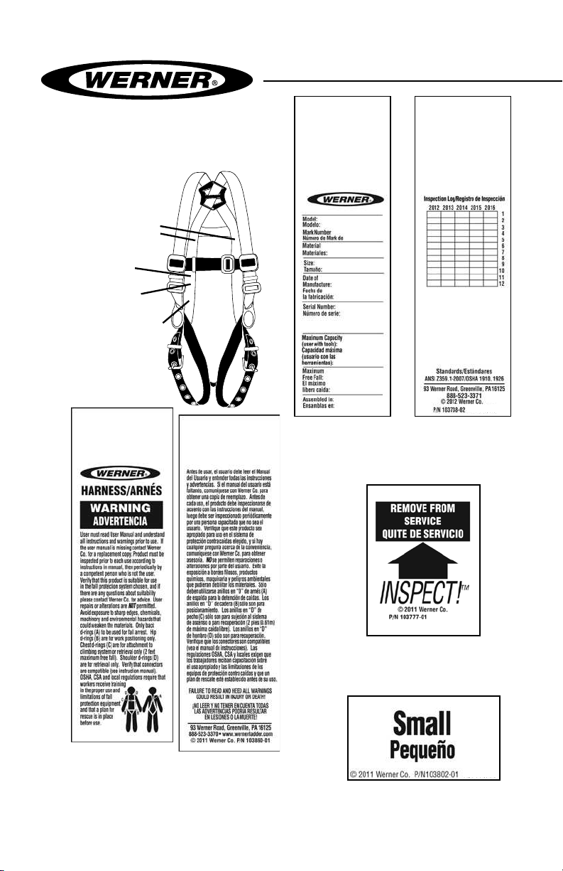
Inspection Labels
Etiqeta de inspección
Size Label
Etiqueta del tamaño
Etiqueta de identicatión
Id label
Warning label
Etiqueta de advertencia
del arnés
Id label front / back
Parte delanter/trasera de la
etiqueta de identicatión
Harness Warning label front / back
Parte delantera / trasera de
ENGLISH
etiqueta de advertencia del arnés
Page 18
Inspection Label
Etiqueta de inspección
Size label
Etiqueta del
tamaño
Page 19

HARNESSES AND BELTS
USER INSTRUCTIONS
Belt Warning label front / back
Parte delantera / trasera de
etiqueta de advertencia del arnés
ENGLISH
Page 19
Page 20
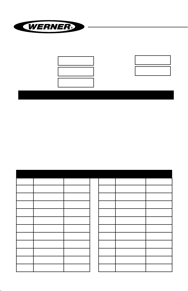
VI. Equipment Record
PART NUMBER
SERIAL NUMBER
DATE
MANUFACTURED
PURCHASE DATE
ASSIGNED TO
SPECIFICATIONS
Werner Harnesses
Certied to meet ANSI Z359.1-2007, and OSHA 1910 and 1926 standards
and regulations for the harness component of a complete personal fall
arrest system.
Individually bar coded model, serial numbers, location and date of
manufacture are on product label.
VII. Inspection Record
INSPECTION RECORD
DAT E INSPECTOR PASS/FAILDAT E INSPECTOR PASS/FAIL
ENGLISH
Page 20
Page 21

ARNESES Y CORREAS
INSTRUCCIONES PARA EL USUARIO
¡PRECAUCIÓN!
Si el uso de equipos de protección contra caídas es necesario,
entonces el ambiente de trabajo es peligroso y potencialmente
mortal. Los productos Werner Company están diseñados para
eliminar peligros tanto como sea posible, pero SÓLO si estos
productos se utilizan correctamente. Utilice este equipo tal como
fue diseñado para usarse, después de una capacitación apropiada,
bajo la supervisión directa de una persona calicada, de acuerdo con
las instrucciones suministradas, y de acuerdo con las regulaciones
OSHA y las regulaciones de seguridad locales. El usuario DEBE leer y
entender todas las precauciones e instrucciones. No tener en cuenta
estas directrices podría resultar en lesiones o incluso la muerte.
Por favor, ¡TRABAJE DE MANERA SEGURA! ¡TRABAJE DE MANERA
INTELIGENTE!
Página 21
ESPAÑOL
Page 22

Contenido
I. ANTES DE UTILIZAR EL ARNÉS ................................................................... 23
a. Inspeccione ............................................................................................................23
b. Compatibilidad .......................................................................................................24
c. Plan de protección contra caídas .........................................................................25
d. Capacitación ..........................................................................................................27
II. DESCRIPCIONES DE LOS ARNESES Y CORREAS .....................................27
a. Tipos de arnés ........................................................................................................27
III. AJUSTE Y USO DEL ARNÉS ........................................................................ 28
a. Ajuste ....................................................................................................................28
b. Realización de conexiones ...................................................................................30
c. Resistencia del anclaje ..........................................................................................33
d. Cuidado y almacenamiento ..................................................................................33
IV. TENGA EN CUENTA LAS ADVERTENCIAS,
RESTRICCIONES Y PRECAUCIONES ......................................................... 34
a. Propósito ................................................................................................................34
b. Capacidad ..............................................................................................................34
c. Limitaciones ...........................................................................................................35
V. ETIQUETAS/IDENTIFICACIÓN/REGISTROS DE INSPECCIÓN ...................36
VI. REGISTROS DE EQUIPOS ........................................................................... 37
VII. REGISTROS DE INSPECCIÓN .................................................................... 37
ESPAÑOL
Página 22
Page 23

ARNESES Y CORREAS
INSTRUCCIONES PARA EL USUARIO
Advertencia:
Este producto es sólo una parte de un sistema personal de detención de
caídas, posicionamiento para el trabajo, limitación de recorrido, ascenso o
rescate. Éste debe combinarse correctamente con otros componentes para
conformar un sistema completo y funcional. El usuario debe entender la
función de cada uno de estos componentes y seguir las instrucciones del
fabricante para el uso de cada componente. Las normas ANSI y OSHA exigen
que una persona calicada suministre capacitación sobre el uso de estos
productos. El usuario debe recibir estas instrucciones, debe leerlas y seguirlas,
y luego debe consultar a la persona calicada que supervisará su trabajo
si tiene alguna pregunta acerca de cualquier parte de las instrucciones.
El empleador debe proporcionar capacitación sobre el uso, inspección y
mantenimiento apropiados de todos los componentes del sistema, y estas
instrucciones pueden utilizarse como parte de esa capacitación. El equipo
SÓLO debe utilizarse de acuerdo con estas instrucciones, ordenanzas y
códigos locales, las normas OSHA y ANSI aplicables, y el plan de seguridad
del empleador. Las alteraciones o uso incorrecto de este producto, o no
seguir estas instrucciones, podría resultar en lesiones graves o la muerte.
SI USTED TIENE ALGUNA PREGUNTA ACERCA DE ALGO DE ESTAS
INSTRUCCIONES, EL EQUIPO O EL USO APROPIADO DEL EQUIPO,
COMUNÍQUESE CON WERNER CO. PARA OBTENER MÁS INFORMACIÓN.
I. Antes de utilizar el arnés
Antes de utilizar este equipo, el usuario debe realizar ciertos pasos para
garantizar que éste está en buenas condiciones y es seguro para su uso.
Algunos de los arneses de Werner se fabrican con una exclusiva Correa
Tejida Inspeccionable WebAlert, que está diseñada para lograr que estas
inspecciones sean más precisas y completas. La correa tejida WebAlert
tiene un color interno contrastante que indicará cualquier sección cortada
o desgastada. La aparición del color interno de la WebAlert indica que el
producto debe recibir una inspección adicional por parte de una persona
calicada antes de continuar su uso. Si la persona calicada determina que
el componente o correa tejida afectada ha perdido resistencia, entonces ese
producto debe retirarse inmediatamente del servicio.
a. Inspeccione
Examine completamente todo el equipo, diariamente antes del uso, y
periódicamente por parte de una persona calicada que no sea el
usuario. Verique la condición de cada componente. Si se encuentra
cualquier daño, anormalidad o desgaste excesivo, el arnés debe retirarse
del servicio.
ESPAÑOL
Página 23
Page 24

ESPAÑOL
1. Revise los indicadores de carga de impacto en la parte trasera del
arnés, debajo del anillo en forma de ‘D’. Si la etiqueta INSPECT!™ está
intacta, revise la costura encima de la etiqueta. Si algún hilo está roto,
el arnés pudo haber sido sometido a una carga de impacto.
2. Inspeccione las correas tejidas en busca de cortaduras, extremos
deshilachados, abrasión, quemaduras, salpicadura de soldadura o
alteración de color que pudiera haberse causado por exposición a
productos químicos. La característica WebAlert, que se encuentra
en algunos de los arneses de Werner, está diseñada para facilitar la
detección de estos daños.
3. Revise todas las costuras en busca de hilos rotos.
4. Inspeccione todos los herrajes en cuanto a grietas, dobladuras, piezas
ojas, irregularidades, corrosión o bordes losos.
5. Revise cada ojal (anillo de refuerzo) en busca de abolladuras, grietas
o, especialmente, desplazamiento. Cualquier daño aquí podría indicar
carga de impacto del arnés.
6. Revise todas las almohadillas plásticas en cuanto a daños o grietas.
Si se encuentra cualquier anormalidad, el producto debe retirarse del
servicio.
7. Verique que todas las etiquetas están en su sitio y son legibles.
Pueden encontrarse ejemplos de etiquetas en la sección IV de estas
instrucciones.
8. Registre la fecha y resultados de la inspección en el registro de
inspección de la página 37.
9. Si se encuentran anormalidades en alguna de estas áreas, entonces
debe consultarse a la persona capacitada para que determine si ese
elemento es seguro para continuar su uso o si debe retirarse del
servicio.
IMPORTANTE si el arnés Werner ha sido sometido a una carga de detención
de caída o carga de impacto, éste debe retirarse inmediatamente del
servicio.
IMPORTANTE no intente realizar reparaciones usted mismo ni alteraciones al
producto. Si existe alguna duda acerca de la seguridad del equipo, retírelo
del servicio.
b. Compatibilidad
Los equipos Werner están diseñados para uso sólo con componentes
y subsistemas aprobados por Werner. Las sustituciones o reemplazos
realizados con componentes o subsistemas no aprobados podrían
arriesgar la compatibilidad del equipo y podrían afectar la seguridad y
conabilidad del sistema completo.
Página 24
Page 25

ARNESES Y CORREAS
INSTRUCCIONES PARA EL USUARIO
Los conectores se consideran compatibles con los elementos conectivos
cuando éstos han sido diseñados para trabajar en conjunto de tal manera
que sus tamaños y formas no causen que sus mecanismos de cierre
se abran inadvertidamente, sin importar la manera como se orienten.
Comuníquese con Werner Co. si usted tiene alguna pregunta acerca de la
compatibilidad. Los conectores (ganchos, argollas rectangulares metálicas
y anillos en ‘D’) deben ser capaces de soportar al menos 22.2 kN (5000
lbs.). Los conectores deben ser compatibles con el ancladero u otros
componentes del sistema. No utilice equipos que no sean compatibles.
Los conectores no compatibles podrían desengancharse accidentalmente.
Los conectores deben ser compatibles en tamaño, forma y resistencia. Las
normas ANSI Z359 y OSHA requieren argollas rectangulares metálicas y
ganchos de cierre resortado auto-asegurables.
c. Plan de protección contra caídas
Planee su sistema de detención o evitamiento de caídas antes de iniciar
su trabajo. Tenga en cuenta todos los factores que afectan su seguridad en
cualquier momento durante el uso. La siguiente lista proporciona algunos
puntos importantes que deben considerarse al planear su sistema:\
1. ANCLADERO: seleccione un punto de anclaje rígido que sea capaz de
soportar las cargas requeridas. Vea la sección III.c. La ubicación del
anclaje debe seleccionarse cuidadosamente para reducir la posibilidad
de peligros por caída libre o por caída tipo columpio, y para evitar
golpear un objeto durante una caída. Para los sistemas de evitamiento
de caídas, el anclaje debe ubicarse de modo que no sea posible
una caída libre vertical. Para los sistemas de detención de caídas,
OSHA exige que el anclaje sea independiente de los elementos que
suspenden o soportan el usuario.
2. CAÍDA LIBRE: no trabaje encima del nivel del anclaje porque existirá
una mayor distancia de caída. Los sistemas personales de detención
de caídas deben instalarse de modo que la posible caída libre nunca
sea superior a 1.83 m (6 pies). Los sistemas de evitamiento de caídas
deben instalarse de modo que no haya posibilidad de caídas libres
verticales.
3. FUERZAS DE DETENCIÓN DE CAÍDAS: el sistema de detención
de caídas ensamblado debe mantener las fuerzas de detención de
caídas por debajo de 8 kN (1800 lbs.) cuando se utiliza con un arnés
de cuerpo completo.
NOTE: no utilice un cinturón de cuerpo para las aplicaciones de detención
de caídas.
Página 25
ESPAÑOL
Page 26

4. CAÍDAS TIPO COLUMPIO: las
0.15 m (½ pie)
Distancia de
caída total
(Caída libre +
Desaceleración)
Caída libre
Nivel de trabajo
Nivel inferior u obstrucción
Cuerda absorbedora
de energía
Longitud del conector del anclaje
1.83 m (6 pies)
Longitud de la cuerda
0.15 m (½ pie)
Alargamiento del anclaje
3.4 m
(11 pies)
1.2 m (4 pies)
Distancia de caída libre con
desaceleración
0.6 m (2 pies)
Factor de seguridad
0.31 m (1 pie)
de alargamiento del arnés
1.5 m (5 pies)
al anillo en “D” de espalda del trabajador
Distancia de caída
estimada total
5.6 m (18.5 pies)
caídas tipo columpio ocurren cuando
el anclaje no está directamente
Anclajes
encima del punto donde ocurre
una caída. La fuerza de golpear
un objeto mientras sucede un
movimiento pendular puede ser
grande y causar lesiones graves.
Minimice las caídas tipo columpio
trabajando tan directamente debajo
del anclaje como sea posible.
Correcto Incorrecto
5. ESPACIO LIBRE DE CAÍDA: verique que existe suciente espacio libre
en la trayectoria de caída para evitar golpear un objeto. La cantidad
de espacio libre necesario depende del tipo de subsistema conectivo
utilizado y de la ubicación del anclaje.
Distancia de caída para las cuerdas absorbedoras de impacto
Peligro de caída
tipo columpio
Distancia de caída para cuerda salvavidas auto-retráctil
ESPAÑOL
Página 26
Nivel inferior u obstrucción
Cuerda salvavidas
auto-retráctil
Nivel de trabajo
Caída libre máxima
Parte inferior de la unidad de cuerda salvavidas retráctil
0.6 m (2 pies)
Caída libre máxima
0.8 m (2.5 pies)
Desaceleración máxima
0.31 m (1 pie)
de alargamiento del arnés
1.5 m (5 pies)
al anillo en “D” de espalda del trabajador
0.6 m (2 pies)
Factor de seguridad
Distancia máxima para
detención (según ANSI)
1.4 m (4.5 pies)
Distancia de caída
estimada total
3.96 m
(13 pies)
Page 27

ARNESES Y CORREAS
INSTRUCCIONES PARA EL USUARIO
6. BORDES FILOSOS: evite trabajar en lugares donde las piezas del
sistema harán contacto con, o se desgastarán contra, bordes losos
expuestos.
7. RESCATE: si ocurre una caída, el usuario (empleador) debe tener un
plan de rescate. Si un trabajador cae y queda obligado a permanecer
suspendido durante cualquier período de tiempo, podría producirse
daño físico o incluso la muerte. Por este motivo Werner, las regulaciones
de OSHA, ANSI y la mayoría de las regulaciones locales exigen la
existencia de un plan de rescate y los medios para ejecutar un plan de
rescate, antes del uso de este equipo.
8. DESPUÉS DE UNA CAÍDA: cualquier equipo que ha sido sometido a
una fuerza de detención de caída debe retirarse inmediatamente del
servicio.
d. Capacitación
Las regulaciones OSHA, ANSI, y la mayoría de las regulaciones locales
exigen que los trabajadores que utilicen este producto deben recibir
capacitación adecuada antes del uso de este producto. Estas instrucciones
y su contenido completo deben ser parte de esa capacitación.
II. Descripciones de los arneses y correas
a. Tipos de arnés
Los arneses tienen una variedad de puntos de sujeción, dependiendo
de su uso pretendido. Utilice el tipo de arnés que sea apropiado para el
trabajo que se realizará.
1. Detención de caídas
El anillo en ‘D’ de espalda o dorsal es el único punto de sujeción
autorizado para uso general de protección contra
caídas, y también puede utilizarse para una
conexión de evitamiento de caídas. La posición de
la sujeción dorsal garantiza que si un trabajador
cae, su cuerpo será orientado primero hacia una
posición con los pies hacia abajo, permitiendo
que la correa sub-pélvica absorba la mayor parte
de la energía de la caída. Es la ÚNICA sujeción
permitida para la detención general de caídas.
2. Posicionamiento para el trabajo
Los anillos en ‘D’ de cadera sólo son para posicionamiento para el
trabajo, generalmente con un conjunto de cadena y barra de refuerzo.
Los anillos en ‘D’ de cadera NUNCA son para la detención de caídas.
Los cinturones de cuerpo con anillos en ‘D’ de cadera pueden utilizarse
para posicionamiento, pero no pueden utilizarse para detención de
caídas.
ESPAÑOL
Página 27
Page 28

Los cinturones de cuerpo para posicionamiento se
utilizan a menudo en conjunto con arneses de cuerpo
entero con anillos en ‘D’ dorsales, para protección
suplementaria de detención de caídas. El uso de
un sistema combinado tal es necesario, porque
un sistema de posicionamiento personal no está
diseñado para propósitos de detención de caídas.
Mediante el uso de este sistema de combinación, los
componentes de detención de caídas se activarán en
caso de que el trabajador sufra una caída al trabajar o
al cambiar posiciones de trabajo.
3. Apoyo/recuperación de personal
Anillos en ‘D’ de hombro. SÓLO se utilizan para el
apoyo y recuperación de personal, generalmente
con un separador de arnés debajo de un pescante
o trípode, y NUNCA para la detención de caídas.
4. Ascenso por escaleras
Anillo en ‘D’ de pecho para cuerdas salvavidas
verticales y escaleras, conexión con una cuerda
o agarradera de cable. Puede utilizarse como
sujeción para detención de caídas SÓLO cuando
la sujeción limita la distancia de caída libre a 0.46
m (18 pulgadas) o menos, y limita la fuerza de
detención máxima a 4 kN (900 lbs.) o menos.
III. Ajuste y uso del arnés
a. Ajuste
Los cierres y abrazaderas del arnés garantizan el
ajuste apropiado del arnés, lo cual es de importancia
fundamental para el uso seguro. Las correas de pecho deben colocarse
a través de la parte media del esternón, no más alto ni más bajo. Las
correas de pierna deben quedar ceñidas. El ajuste demasiado ojo de
las correas de pierna causará lesiones en caso de una caída. Los ajustes
correctos del arnés colocarán la correa subpélvica de manera ceñida
por debajo de los glúteos, la posición necesaria para absorber energía
en caso de una caída, y también para proporcionar algo de alivio por el
trauma de suspensión después de la ocurrencia de una caída. La posición
subpélvica correcta es el resultado de la combinación correcta de todos
los ajustes del arnés.
ESPAÑOL
Página 28
Page 29

ARNESES Y CORREAS
INSTRUCCIONES PARA EL USUARIO
1. Hebilla de lengüeta
i. El tipo de cierre de pierna más común, con
función similar al cinturón que sostiene sus
pantalones. Verique que las correas no están
retorcidas.
ii. Coloque el extremo abierto de la correa con
ojales a través de la hebilla, hale hasta que
quede ceñido en la pierna y enganche la
lengüeta dentro de un ojal.
iii. El usuario DEBE vericar que los extremos de la correa tejida
están metidos dentro de las abrazaderas para correa tejida, para
mantener conectado este tipo de hebilla mientras está en uso. No
asegurar apropiadamente los extremos de la correa de pierna en
las abrazaderas podría resultar en desenganche involuntario.
2. Hebilla de acople/pasante
i. Verique que las correas no están retorcidas y
que el extremo suelto está en el lado externo.
ii. Pase la hebilla con la barra central a través
de la hebilla abierta. La ranura ayudará. Hale
para garantizar que la hebilla está en su sitio.
iii. Hale la correa tejida para apretar la correa de
modo que haya un ajuste ceñido.
iv. El usuario DEBE deslizar las abrazaderas plásticas hasta el extremo
de correa o encontrar otra ubicación para meter el extremo, a n
de garantizar que no hay extremos ojos ni colgantes.
3. Conexión rápida
i. Verique que las correas no están retorcidas
y que el extremo suelto de la correa tejida
está en el lado externo.
ii. Hale la correa tejida a través del ajustador
para aojar o apretar hasta que quede
ceñida.
iii. Inserte el conector macho dentro de la hebilla,
hale las correas para vericar el enganche
rme.
iv. El usuario DEBE deslizar las abrazaderas plásticas hasta el
extremo de correa o encontrar otra ubicación para meter el extremo,
a n de garantizar que no hay extremos ojos ni colgantes.
ESPAÑOL
Página 29
Page 30

ESPAÑOL
Página 30
4. Ajustador de longitud del torso
i. El ajustador de torso garantiza el ajuste
general del arnés. Verique que la correa
subpélvica está situada debajo de los glúteos.
Si está demasiado alta, el ajustador de torso
debe aojarse para bajar la correa sub-pélvica.
Si está demasiado baja, el ajustador de torso
puede apretarse para elevar la correa subpélvica.
ii.
Para acortar o alargar la correa tejida de torso,
empuje hacia abajo la parte superior del ajustador de torso de
modo que quede horizontal.
iii. Hale hacia arriba la correa tejida interior para alargar, o hale hacia
arriba la correa tejida exterior para acortar la longitud de torso.
Para los arneses BaseWear, suelte la hebilla de acople pequeña
fuera del elemento pasante más grande para permitir que la correa
tejida pase a través del ajustador de torso.
iv. Al tener la longitud correcta, deslice la
abrazadera plástica inferior hacia abajo
acercándose al ajustador de torso y la
abrazadera plástica superior hacia arriba, de
modo que el extremo de la correa tejida no
quede colgando.
5. Abrazaderas para correa tejida
Todos los extremos de las correas tejidas están
equipados con abrazaderas plásticas, que son importantes para el uso
seguro del arnés. Deslizar una abrazadera acercándose a las hebillas
asegura que la hebilla no se pueda abrir o mover accidentalmente
mientras está en uso. Deslizar la otra acercándose hacia el extremo de
la correa evita que se aoje y quede colgante, y un posible peligro de
enredo.
6. Unión de las correas a los arneses
Algunos arneses de Werner hechos sin correas integradas tienen lazos
a través de los cuales pueden envolverse correas accesorias, para unir
el accesorio al arnés. Los lazos se encuentran en el interior de la correa
tejida del arnés, debajo de los indicadores de impacto.
b. Realización de conexiones
1. Con este equipo, sólo utilice argollas rectangulares metálicas y ganchos
de cierre resortado auto-asegurables. Sólo utilice conectores que sean
apropiados para cada aplicación. Verique que todas las conexiones
son compatibles en tamaño, forma y resistencia. No utilice equipos
que no sean compatibles. Verique que todos los conectores están
totalmente cerrados y asegurados.
Page 31

ARNESES Y CORREAS
INSTRUCCIONES PARA EL USUARIO
2. Los conectores Werner Co.
(ganchos de cierre resortado y
argollas rectangulares metálicas)
están diseñados para utilizarse
únicamente según se especica
en las instrucciones para usuario
de cada producto. Vea abajo
para conocer las conexiones
CONEXIONES INAPROPIADAS
NO! NO! NO! NO!
inapropiadas.
Werner Los ganchos de cierre resortado y las argollas rectangulares
metálicas de Werner Co. NO deben conectarse:
i. a un anillo en ‘D’ al cual está sujetado otro conector.
ii. de tal manera que se produzca carga sobre el cierre. Si el elemento
conectivo al cual se sujeta un gancho de cierre resortado o una
argolla rectangular metálica es de tamaño inferior o tiene forma
irregular, podría ocurrir un problema cuando el elemento conectivo
aplique una fuerza al cierre del gancho de cierre resortado o la
argolla rectangular metálica. Esta fuerza podría causar que se
abra el cierre (de un gancho de cierre resortado auto-asegurable
o no-asegurable), permitiendo que el gancho de cierre resortado
o la argolla rectangular metálica se desenganche del punto de
conexión.
NOTA: los ganchos de cierre resortado que se abren hasta una garganta
grande no deben conectarse a anillos en ‘D’ de tamaño estándar u
objetos similares, lo cual resultará en una carga sobre el cierre si el
gancho o anillo en ‘D’ gira o rota. Los ganchos de cierre resortado de
garganta grande están diseñados para uso en elementos estructurales
jos tales como barras de refuerzo o travesaños que no tengan una
forma que pueda atrapar el cierre del gancho.
iii. en un enganche falso, donde las características que sobresalen
del gancho de cierre resortado o la argolla rectangular metálica
se agarran al anclaje, y sin conrmación visual parece estar
CONEXIÓN APROPIADA
NO!NO!NO!NO!
ESPAÑOL
Página 31
Page 32
totalmente enganchado al punto de anclaje.
iv. uno al otro.
v. directamente a una correa tejida o cuerda de bras trenzadas o
amarre sobre sí mismo (a menos que las instrucciones del
fabricante de la cuerda y el conector permitan especícamente
dicha conexión).
vi. a cualquier objeto que tenga una forma o dimensiones tales que el
gancho de cierre resortado o la argolla rectangular metálica no se
cierren ni aseguren, y que pudiera ocurrir rodaje.
3. Uso correcto de los anillos en ‘D’
i. Para las aplicaciones de detención de
caídas, conecte al anillo en ‘D’ dorsal
ubicado entre los hombros en la parte
trasera del arnés de cuerpo completo.
Los anillos en ‘D’ delanteros pueden
utilizarse para la detención de caídas
sólo en aplicaciones en las que el
sistema personal de detención de caídas
limita la distancia de caída libre máxima
a 0.6 m (2 pies) y limita la fuerza de detención máxima a 4.0 kN
(900 lbs.).
ii. Para las aplicaciones de evitamiento de caídas, puede utilizarse
la sujeción dorsal o frontal del arnés. Si se utiliza un cinturón de
cuerpo para las aplicaciones de evitamiento de caídas, conecte al
anillo en ‘D’ opuesto a la carga de evitamiento de caídas.
iii. Para aplicaciones de posicionamiento pueden utilizarse los anillos
en ‘D’ delanteros o laterales.
iv. Los anillos en ‘D’ de hombro sólo son para recuperación.
4. El extremo con paquete de una cuerda absorbedora de energía
con paquete contra impacto, o el extremo designado de una cuerda
absorbedora de impacto interna, debe sujetarse al anillo en ‘D’ trasero
del arnés. Con las cuerdas de tramo doble, el gancho central debe
conectarse al arnés.
5. Para conectar una cuerda con un lazo de correa tejida, pase el lazo de
correa tejida a través del anillo en ‘D’ trasero del arnés. Inserte el otro
extremo de la cuerda a través del lazo de correa tejida. Hale la cuerda
todo el recorrido a través del lazo de correa tejida para apretar sobre el
1
ESPAÑOL
Página 32
2
anillo en ‘D’ del arnés de manera estrangulante.
3
Page 33

ARNESES Y CORREAS
INSTRUCCIONES PARA EL USUARIO
c. Resistencia del anclaje
La resistencia requerida del anclaje depende de la aplicación. Se indican
a continuación los requisitos de resistencia del anclaje para aplicaciones
especícas:
1.DETENCIÓN DE CAÍDAS: los ancladeros seleccionados para los
Sistemas Personales de Detención de Caídas (SPDC) deberán tener
una resistencia capaz de sostener cargas estáticas, aplicadas en las
direcciones permitidas por el SPDC, de al menos (A) 16 kN (3600 lbs.)
cuando existe certicación (vea la norma ANSI Z359.1 para obtener
la denición de certicación), o (B) 22 kN (5000 lbs.) en ausencia de
certicación. Cuando se sujeta más de un (1) SPDC a un ancladero, las
resistencias del ancladero establecidas en (A) y (B) anteriores deberán
multiplicarse por el número de sistemas personales de detención de
caídas sujetados al ancladero. Según las normas OSHA 1926.500 y
1910.66, los ancladeros utilizados para sujeción de los SPDC deberán
ser independientes de cualquier ancladero que se esté utilizando para
soportar o suspender plataformas, y capaces de soportar al menos
22 kN (5000 lbs.) por cada usuario sujetado, o diseñarse, instalarse y
utilizarse como parte de un sistema completo personal de detención
de caídas que mantenga un factor de seguridad de dos como mínimo
y sea supervisado por una persona capacitada.
2. EVITAMIENTO DE CAÍDAS: el anclaje debe sostener cargas estáticas,
aplicadas en las direcciones permitidas por el sistema de evitamiento
de caídas, de al menos 13.3kN (3000 lbs.) Cuando se sujeta más de
un (1) sistema de evitamiento de caídas a un anclaje, las resistencias
indicadas anteriormente deben multiplicarse por el número de sistemas
de evitamiento de caídas sujetados al anclaje.
Advertencia:
Los anclajes para evitamiento de caídas sólo pueden utilizarse donde no existe
la posibilidad de una caída libre vertical. Los anclajes para evitamiento de caídas
no tienen suciente resistencia para detener una caída. No conecte los sistemas
personales de detención de caídas a anclajes para evitamiento de caídas.
3. POSICIONAMIENTO PARA EL TRABAJO: el anclaje debe sostener
cargas estáticas, aplicadas en las direcciones permitidas por el sistema
de posicionamiento para el trabajo, de al menos 13.3kN (3000 lbs.) o
dos veces la carga de impacto potencial, la que sea superior. Cuando
se sujeta más de un sistema de posicionamiento para el trabajo a un
anclaje, las resistencias indicadas anteriormente deben multiplicarse
por el número de sistemas de evitamiento de caidas sujetados al
anclaje.
d. Cuidado y almacenamiento
El producto puede limpiarse de manchas utilizando un detergente suave
sin blanqueador de lavado de ropa en agua tibia o fría, y secarse al aire o
en máquina al nivel de calor más bajo. Guarde en un lugar fresco y seco
protegido de la exposición a cualquier luz directa.
Página 33
ESPAÑOL
Page 34

IV. Tenga en cuenta las advertencias,
restricciones y precauciones
a. Propósito
Los arneses de cuerpo completo y cinturones de cuerpo de Werner son
para utilizar como componentes en sistemas personales de detención de
caídas, evitamiento de caídas, posicionamiento para el trabajo, ascenso
o rescate de personal. Los arneses y correas incluidos en este manual
cumplen con los requisitos de ANSI Z359.1 y OSHA.
1. DETENCIÓN DE CAÍDAS PERSONAL: el arnés de cuerpo completo
se utiliza como componente de un sistema personal de detención de
caídas. Los sistemas personales de detención de caídas incluyen
normalmente un arnés de cuerpo completo y un subsistema de
conexión (cuerda absorbedora de energía). La fuerza de detención
máxima no debe superar 8 kN (1800 lbs.).
2. EVITAMIENTO DE CAÍDAS: el arnés de cuerpo completo se utiliza
como componente de un sistema de evitamiento de caídas, para
evitar que el usuario llegue a tener un peligro de caída. Los sistemas
de evitamiento de caídas incluyen normalmente un arnés de cuerpo
completo y una cuerda o cuerda de evitamiento de caídas.
3. POSICIONAMIENTO PARA EL TRABAJO: el arnés de cuerpo completo
se utiliza como componente de un sistema de posicionamiento para
el trabajo, para soportar al usuario en una posición de trabajo. Los
sistemas de posicionamiento para el trabajo incluyen normalmente
un arnés de cuerpo completo, una cuerda de posicionamiento y un
sistema personal de detención de caídas como respaldo.
b. Capacidad
ESPAÑOL
Página 34
4. ASCENSO: el arnés de cuerpo completo se utiliza como componente
de un sistema de ascenso, para evitar que el usuario caiga cuando
asciende por una escalera u otra estructura de ascenso. Los sistemas
de ascenso incluyen normalmente un arnés de cuerpo completo, un
riel o cable vertical sujeto a la estructura, y un manguito de ascenso.
5. RECUPERACIÓN: el arnés de cuerpo completo se utiliza como
componente de un sistema de recuperación. Los sistemas de
recuperación se conguran en función del tipo de recuperación.
Capacidad máxima para la Blue Armor 1000 y 2000 arnés es 181.8kg
(400lbs) y 140.6 kg (310 lbs) para todas las otras series para es peso
combinado de un trabajador y todas las herramientas cuando hacen parte
de un sistema completo de protección contra caídas.
Page 35

ARNESES Y CORREAS
INSTRUCCIONES PARA EL USUARIO
c. Limitaciones
Las siguientes limitaciones de aplicación deben reconocerse y tenerse en
cuenta antes de utilizar este producto:
1. CAÍDA LIBRE: los sistemas de evitamiento de caídas deben instalarse
de modo que no haya posibilidad de caídas libres verticales. Los
sistemas personales de detención de caídas deben instalarse de tal
manera que limiten una caída libre a 1.83 m (6 pies) (ANSI Z359.1). Los
sistemas de posicionamiento para el trabajo deben instalarse de modo
que la caída libre se limite a 0.6 m (2 pies) o menos. Los sistemas de
ascenso deben instalarse de modo que la caída libre se limite a 0.46 m
(1.5 pies) o menos. Vea las instrucciones del fabricante del subsistema
conectivo asociado para obtener información adicional.
2. ESPACIO LIBRE DE CAÍDA: verique que existe suciente espacio
libre en la trayectoria de caída para evitar golpes con un objeto. La
cantidad de espacio libre requerido depende del tipo de subsistema
conectivo utilizado (cuerda, cuerda salvavidas), la ubicación del
anclaje, y la cantidad de alargamiento de la cuerda salvavidas.
3. SUSPENSIÓN EXTENDIDA: un arnés de cuerpo completo no está
diseñado para su utilización en aplicaciones de suspensión extendida.
4. CORROSIÓN: no deje este equipo durante períodos largos en
ambientes donde pudiera ocurrir corrosión de las piezas metálicas
como resultado de vapores procedentes de materiales orgánicos. Los
alcantarillados y fábricas de fertilizantes, por ejemplo, tienen altas
concentraciones de amoniaco. El uso cerca del agua de mar u otros
ambientes corrosivos podría requerir inspecciones más frecuentes o
servicio de mantenimiento para garantizar que el daño por corrosión
no está afectando el funcionamiento del producto.
5. PELIGROS POR SUSTANCIAS QUÍMICAS: las soluciones que
contienen ácidos, álcalis u otras sustancias cáusticas, especialmente a
temperaturas elevadas, podrían causar daño a este equipo. Al trabajar
con dichos productos químicos, debe realizarse una inspección
frecuente de estos equipos. Consulte a Werner Co. si existen dudas
relacionadas con el uso de este equipo en zonas de peligro por
sustancias químicas.
6. CALOR: este equipo no está diseñado para usarse en ambientes a
temperaturas altas. Debe suministrarse protección para este equipo
al utilizar cerca de actividades de soldadura, corte de metales o
actividades similares. Las chispas calientes podrían quemar o dañar
este equipo. Consulte con Werner Co. para obtener detalles sobre los
ambientes de alta temperatura.
7. PELIGROS ELÉCTRICOS: debido a la posibilidad de ujo de corriente
eléctrica a través de este equipo o los componentes conectivos, tenga
extremo cuidado al trabajar cerca de cables de energía de alto voltaje.
ESPAÑOL
Página 35
Page 36

8. COMPATIBILIDAD DE LOS COMPONENTES: los arneses y cinturones
de cuerpo mencionados en estas instrucciones están diseñados sólo
para uso con subsistemas aprobados por Werner Co. Consulte a
Werner Co. si tiene preguntas acerca de la compatibilidad.
9. CAPACITACIÓN: este equipo debe ser utilizado por personas que han
sido capacitadas apropiadamente en cuanto a su aplicación y uso
correctos.
V. Etiquetas/Identicación/Registros de inspección
a. Todos los productos deben ser inspeccionados completamente por el
usuario antes de cada uso. Una persona capacitada diferente al usuario
debe realizar inspecciones adicionales, al menos anualmente. Ese intervalo
debe acortarse cada vez que el producto se utiliza en un ambiente agresivo
o se expone a condiciones tales como productos químicos, abrasión, calor
o cualquier otro factor que pudiera afectar la resistencia de cualquiera de
los materiales o componentes.
b. Las etiquetas del arnés proporcionan una tabla de inspección para registrar
estas inspecciones por parte una persona calicada. Utilice un punzón o
marcador permanente para registrar estos datos.
c. Este manual siempre debe acompañar el producto o estar en los archivos
del empleador para consultarlo cuando se requiera. Registre los detalles de
identicación del arnés y registre las inspecciones en el siguiente registro
de inspección en la pagina 37. Es importante mantener este registro con
información completa y actualizada, y ponerlo a disposición según se
necesite.
ESPAÑOL
Página 36
Page 37
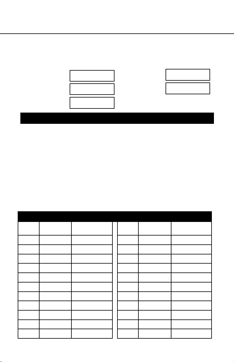
VI. Registro del equipo
ARNESES Y CORREAS
INSTRUCCIONES PARA EL USUARIO
NÚMERO DE
PIEZA
NÚMERO DE SERIE
FECHA DE
FABRICACIÓN
FECHA DE COMPRA
ASIGNADO A
ESPECIFICACIONES
Anclaje de agarre manual, Werner
Certicado para cumplir las regulaciones y normas ANSI Z359.1-2007 y
OSHA 1910 y 1926 para los componentes de subsistemas de un sistema
personal completo de detención de caídas.
VII . Registro de inspección
REGISTRO DE INSPECCIÓN
FECHA INSPECTOR APROBADO/
NO-APROBADO
FECHA INSPECTOR APROBADO/
NO-APROBADO
Página 37
ESPAÑOL
Page 38

NOTES / NOTAZ
ESPAÑOL
Página 38
Page 39

ARNESES Y CORREAS
INSTRUCCIONES PARA EL USUARIO
NOTES / NOTAZ
Página 39
ESPAÑOL
Page 40

Werner Co. Fall Protection
93 Werner Rd. Greenville, PA 16125
724-588-2000 • 888-523-3371 toll free/ llamada gratuita • 888-456-8458 fax
105466-02 ©2015 Werner Co. Rev B 10/15
 Loading...