

Page 1
USER INSTRUCTIONS
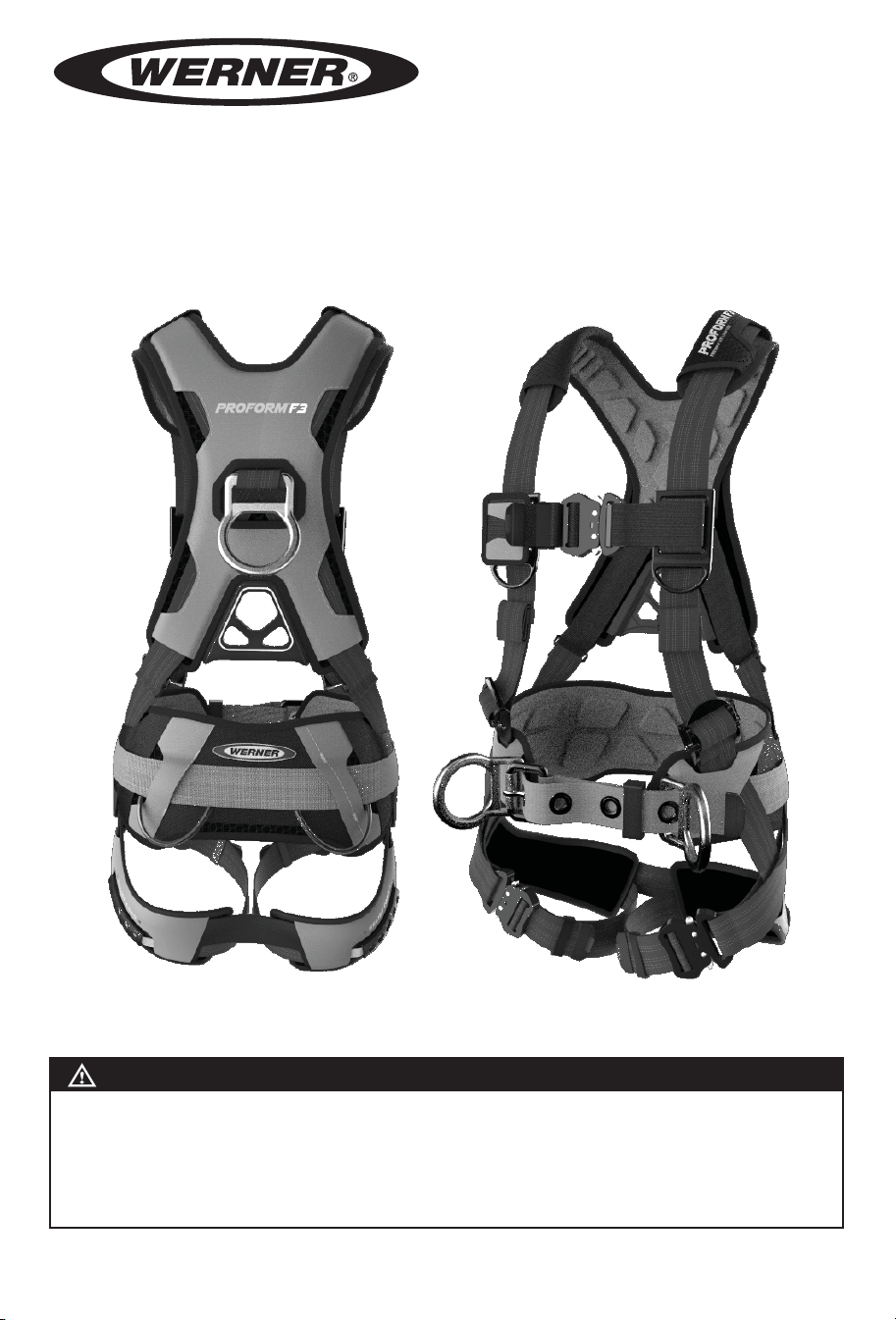
FULL BODY HARNESS
Complies with the ANSI Z359.11 standard and OSHA 29 CFR 1910 and 1926 regulations.
(This manual applies to all harnesses with model numbers starting with H0 and H9)
WARNING!
Compliant fall protection equipment must only be used as it was designed. Users MUST read and follow
all user instructions provided with the product. Before using a fall arrest system, users must be trained in
the safe use of the system, as required by OSHA 29 CFR 1910.30 and 1926.503, or local safety regulations.
Misuse or failure to heed these warnings and instructions may result in injury or even death.
WORK SAFE! WORK SMART!
IF YOU HAVE ANY QUESTIONS ABOUT THE PROPER USE OF THE EQUIPMENT, SEE YOUR SUPERVISOR, USER
INSTRUCTIONS, OR CONTACT WERNER CO. FOR MORE INFORMATION.
Page 2

USE INSTRUCTIONS AND LIMITATIONS
IMPORTANT
Before use, the user must read and understand these User Instructions. Keep these User Instructions for
reference.
PURPOSE
The Full Body Harness is designed to be used as part of a complete personal fall arrest, restraint, rescue, ladder
climbing, or work positioning system.
USE INSTRUCTIONS
1. Failure to follow all instructions and limitations on the use of the Full Body Harness may result in serious
personal injury or death.
2. Before using a personal fall arrest system, employees must be trained in accordance with the requirements of
OSHA 29 CFR 1910.30 and 1926.503 in the safe use of the system and its components.
3. Personal fall arrest systems, including the Full Body Harness, must be inspected prior to each use for wear,
damage, and other deterioration. Defective components must be immediately removed from service, in
accordance with the requirements of OSHA 29 CFR 1910.140 and 1926.502.
4. The complete fall protection system must be planned (including all components, calculating fall clearance,
and swing fall) before using.
5. Users must have a rescue plan, and the means to implement it, that provides for the prompt rescue of
employees in the event of a fall, or assures that employees are able to rescue themselves.
6. Store the Full Body Harness in a cool, dry, clean environment and out of direct sunlight when not in use.
7. After a fall occurs on the system, immediately remove from service until a “competent person” can make the
determination for reuse or disposal.
USE LIMITATIONS
1. CAPACITY: The Full Body Harness is designed for users with a capacity (including clothing, tools, etc.) up to
400 pounds (181 kg) total working weight, in conjunction with compatible connecting components.
WARNING!
Not all fall protection components are rated for the same user weight capacity. Only use components
rated for the same weight capacity.
2. FREE FALL: Personal fall arrest systems must be rigged in such a way to limit the free fall to 6 ft. (1.83 m)
(OSHA 1910.140 and1926.502). Work positioning systems must be rigged so that free fall is limited to 2 ft.
(0.6 m) or less. Climbing systems must be rigged so that free fall is limited to 1.5 ft. (0.46 m) or less. Restraint
systems must be rigged such that there is no possible vertical free fall. See associated connecting subsystem
manufacturer’s instructions for further information.
3. FALL CLEARANCE: Ensure that enough clearance exists in your fall path to prevent striking an object. The
amount of clearance required is dependent upon the type of connecting subsystem used (energy absorbing
lanyard, self retracting lifeline), the anchorage location, and the amount of stretch in the harness.
WARNING!
The Full Body Harness Stretch (FBH Stretch) and additional length of a D-ring extender must be taken
into consideration during the clearance calculation process.
4. EXTENDED SUSPENSION: The Full Body Harness is not intended for use in extended suspension
applications.
5. CORROSION: Do not leave the Full Body Harness in environments where corrosion of metal parts could take
place as a result of vapors from organic materials. Use near seawater or other corrosive environments may
require more frequent inspections to ensure corrosion damage is not affecting the performance of the product.
6. CHEMICAL HAZARDS: Solutions containing acids, alkali, or other caustic chemicals, especially at elevated
temperatures, may cause damage to the Full Body Harness. When working with such chemicals, frequent
inspection of this equipment must be performed. Contact Werner Co. with any questions concerning the use
of the Full Body Harness around chemical hazards.
7. EXTREME TEMPERATURE: The Full Body Harness is designed to be used in temperatures ranging
from -40ºF to +130ºF (-40°C to +54°C). Protection should be provided for Full Body Harness when used
near welding, metal cutting or similar activities. Contact Werner Co. with any questions concerning high
temperature environments.
8. ELECTRICAL HAZARDS: Use extreme caution when working near high voltage power lines due to the
possibility of electric current owing through the Full Body Harness or connecting components.
9. HEALTH: Minors, pregnant women and anyone with a history of either back or neck problems should not use
this equipment.
Page 3
1. TRAINING: Do not use the Full Body Harness without proper training from a “competent person” as de ned by OSHA
29 CFR 1910.140(b) and 1926.32(f).
2. REPAIRS: Only Werner Co., or persons or entities authorized in writing by Werner Co., may make repairs or alterations
to the equipment.
ANCHORAGES
All anchorage requirements depend on the application which the Full Body Harness is used. In a personal fall arrest system
the anchorage must meet the requirements of OSHA 29 CFR 1910 and 1926. OSHA states:
Anchorages must be capable of supporting at least 5,000 pounds (22.2 kN) for each employee attached; or designed,
installed, and used, under the supervision of quali ed person, as part of a complete personal fall protection system
that maintains a safety factor of at least two.
ANSI Z359.2 states that anchorages selected for fall arrest systems must have a strength capable of sustaining static loads,
applied in all permitted directions by the system:
(a) no less than 5,000 pounds (22.2 kN) for non certi ed anchorages; or
(b) at least two times the maximum arresting force for certi ed anchorages;
When more than one fall arrest system is attached to an anchorage, the strengths set forth in (a) and (b) above shall be
multiplied by the number of systems attached to the anchorage.
Anchorages used in restraint systems must be capable of supporting loads of 1,000 lbf (4.5 kN) for non-certi ed anchorages
or at least two times the foreseeable force for certi ed anchorages per ANSI Z359.2.
Anchorages used in work positioning systems must be capable of supporting loads of 3,000 lbf (13.3 kN) for non-certi ed
anchorages or two times the foreseeable force for certi ed anchorages per ANSI Z359.2.
Anchorages used in controlled descent and rescue systems must be capable of supporting loads of 3,100 lbf (13.8 kN) for
non-certi ed anchorages or a 5:1 safety factor for certi ed anchorages per ANSI Z359.4-2007.
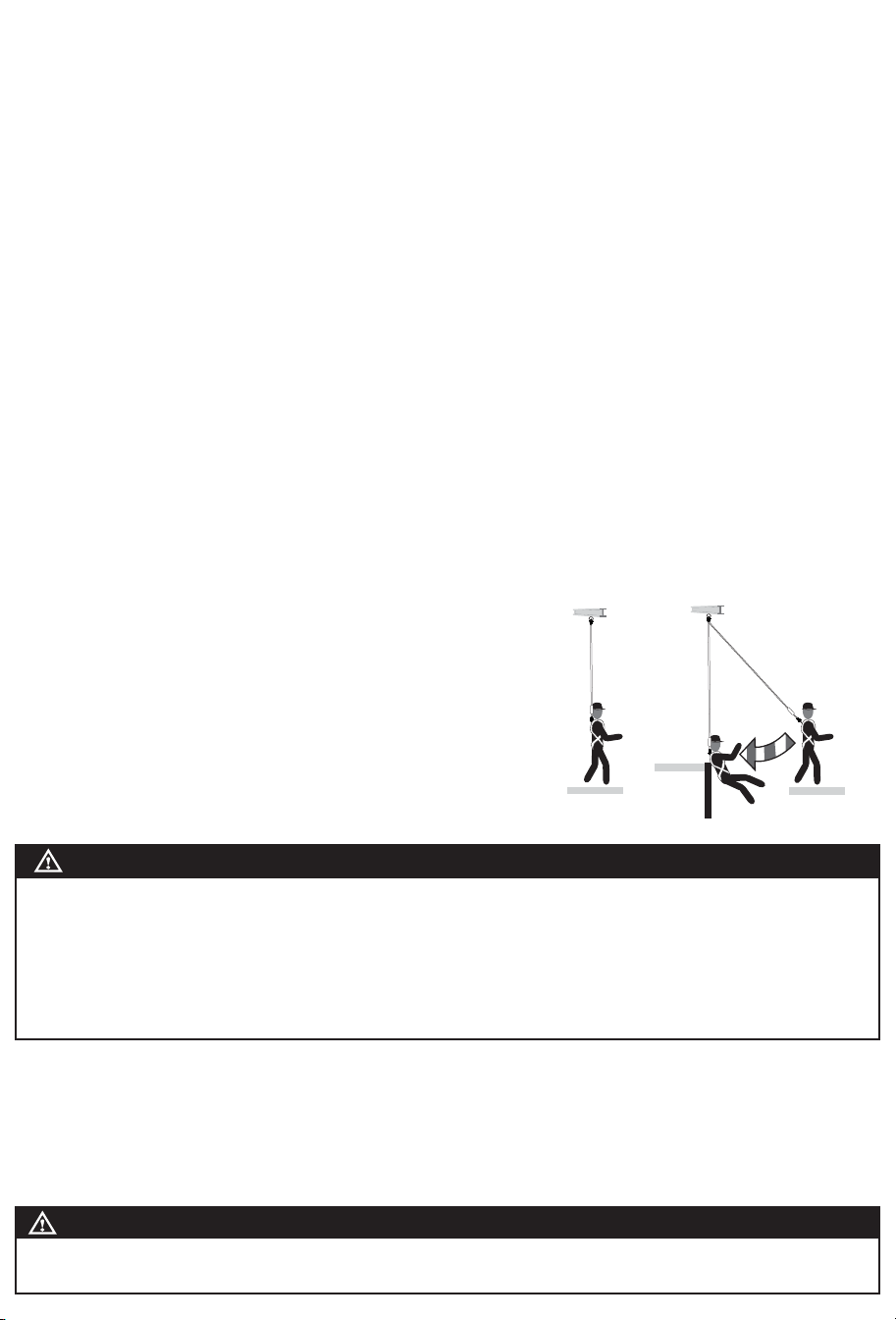
SWING FALL
All anchorages should be located vertically above the user’s head and be
positioned as to not exceed the maximum allowable free fall for the system.
Anchorages
HAZARD
SWING FALLS
To minimize the possibility of a swing fall, anchor as directly above the work
area as possible. Striking objects horizontally, due to the pendulum effect,
may cause serious injury. Swing falls also increase the vertical fall distance of
a worker, compared to a fall directly below the anchorage connector. Swing
falls may be reduced by using overhead anchorage connectors that move
with the worker.
Correct Incorrect
DONNING AND USE
WARNING!
Before using a personal fall arrest system, employees must be trained in accordance with the requirements of
OSHA 29 CFR 1910.30 and 1926.503 and/or applicable local, state, governmental and jurisdictional agencies, in the
safe use of the system and its components.
Personal fall arrest systems, including Full Body Harnesses, must be inspected prior to each use for wear, damage,
and other deterioration, and defective components must be immediately removed from service in accordance with
the requirements of OSHA 29 CFR 1910.140 and 1926.502 and/or applicable local governmental and jurisdictional
standards.
DONNING
1. Hold the dorsal (back) D-ring of the Full Body Harness and shake to allow all straps to fall into place. Ensure straps are
not buckled or twisted.
2. Slip shoulder strap over one shoulder, then pull the other shoulder strap around the back and over the second shoulder,
just like putting on a jacket. The dorsal D-ring will be located on your back, while the chest strap is located in the front.
Straps must not be tangled as the harness hangs freely from shoulders.
3. Pull one leg strap between your legs and connect it to the opposite end on the same side. See Fitting for speci c
connecting type. Repeat with second leg strap. Ensure that the leg straps are not twisted or crossed.
WARNING!
Failure to have the leg straps of a Full Body Harness connected and properly adjusted in the event of a fall arrest
may result in serious personal injury or death.
Page 4

1. Fasten the chest strap across the lower chest just below the nipple line. Chest strap should be snug, with excess strap
secured through the web keepers.
FITTING
Adjust shoulder straps with the two adjusters located at the lower end of the shoulder strap. Adjust the left and right sides to
the same length. The chest strap, and front (sternal) D-ring if applicable, must be centered on your lower chest. Adjustment
of the shoulder straps may cause the dorsal D-ring to move and may need to be repositioned to achieve the correct position
between the shoulder blades. Once the D-ring is repositioned, the dual layer shoulder padding positioning can be adjusted
using the black web hook and loop between the layered pads. After all straps have been tightened and Full Body Harness
ts snugly, secure all excess straps through the web keepers.
Correct Full Body Harness adjustments will place the sub-pelvic strap snugly below the buttocks where the relief cord can
be utilized to help with the discomfort of suspension after a fall occurs. Correct sub-pelvic position is the result of the correct
combination of all the Full Body Harness adjustments.
QUICK CONNECT
Ensure that the leg straps are not twisted and the loose webbing end is on the outside. Insert male connector
into the receiving end of the buckle. You will hear a click and on the ProForm see a green circle when engaged
correctly. Pull webbing through adjuster to loosen or tighten until snug. Slide plastic web keepers to the strap end
to secure the excess webbing.
TONGUE BUCKLE
Ensure that the leg straps are not twisted. Put the open end of the leg strap with grommets through the buckle,
pulling until it is snug on the leg and engage the tongue into a grommet. Webbing ends must be tucked into the
web keepers to ensure this type of buckle stays connected while in use. Failure to properly secure the leg strap
ends in the keepers could result in unintentional disengagement.
MATING/PASS-THROUGH BUCKLE
Ensure that the leg straps are not twisted and the loose end is on the outside. Pass the buckle with the center
bar through the open buckle. The slot will assist. Tug to ensure buckle is in place. Pull the webbing to tighten the
strap so there is a snug t. Slide plastic web keepers to the strap end to secure the excess webbing.
TORSO LENGTH ADJUSTER
The torso adjuster ensures the overall t of the Full Body Harness. Check to see that the sub-pelvic strap is
situated below the buttocks. If the sub-pelvic strap is too high, the torso adjuster should be loosened to lower it. If
the sub-pelvic strap is too low, the torso adjuster can be tightened to raise it.
To shorten or lengthen the torso webbing push the top of the torso adjuster down, so it is horizontal, allowing
web to ow through the torso adjuster. Release when at the right length. Slide the lower plastic web keeper
down near the torso adjuster and the upper plastic keeper up to secure the excess webbing.
WEB KEEPERS
All webbing ends are equipped with plastic web keepers to secure the excess webbing and aid in the safe use of
the Full Body Harness. Sliding one keeper close to the buckles helps secure the buckle in position while in use.
Sliding the other close to the end of the strap secures the excess webbing and helps prevent a possible snag
hazard. On the Proform, roll the excess webbing and secure to the webbing with the hook and loop keeper.
Attaching Belts to Harness
Werner Co. Full Body Harnesses made without integrated belts have loops through which accessory belts can be attached,
joining the accessory to the harness. The loops are found on the inside of the harness webbing, below the impact indicators.
LANYARD PARKING ATTACHMENT
Lanyard parking attachments are located on all Full Body Harnesses where the shoulder strap meets the chest strap.
Lanyard parking attachments are approved only for the connection of the unused lanyard leg to the Full Body Harness.
WARNING!
Never attach the unused leg of the lanyard back to the Full Body Harness at any location other than an approved
lanyard parking attachment.
LOAD INDICATOR
Full Body Harnesses include a built-in fall arrest load indicator that activates to give a permanent, readily visible INSPECT!™
after the Full Body Harness has arrested a fall, or has been subjected to an equivalent force.
GEAR LOOPS
Gear loops are provided on Construction model harness. For use with Tool Lanyards only.
Page 5

RELIEF CORD
The ProForm Full Body Harness is equipped with
the Relief Cord and is designed to help with the
discomfort of suspension after a fall occurs. To use
the Relief Cord:
1. Slide Chest strap down away from the throat, by
grabbing the lanyard keeper and pulling down.
2. Grab the relief cord handles and pull out and forward, while lifting legs to a seated position.
3. Readjust chest strap down away from the throat. The outer layer shoulder pad can be pulled down for additional comfort.
CONNECTION REQUIREMENTS
COMPATIBLE CONNECTIONS INCOMPATIBLE CONNECTIONS
NO! NO! NO! NO!
NO!NO!NO!NO!
COMPATIBILITY LIMITATIONS
All connecting subsystems must only be coupled to compatible connectors. OSHA 29 CFR 1910.140 and 1926.502 prohibit
snap hooks from being engaged to certain objects unless two requirements are met: snap hook must be a locking type and
must be “designed for” making such a connection. Under OSHA “designed for” means that the manufacturer of the snap
hook speci cally designed the snap hook to be used to connect to the equipment in question.
The following connections must be avoided, because they can result in rollout* when a non locking snap hook is used:
• Direct connection of a snap hook to horizontal lifeline.
• Two (or more) snap hooks connected to one D-ring.
• Two snap hooks connected to each other.
• A snap hook connected back on its integral lanyard.
• A snap hook connected to a webbing loop or webbing lanyard.
• Improper dimensions of the D-ring, rebar, or other connection point in relation to the snap hook dimensions that
would allow the snap hook keeper to be depressed by a turning motion of the snap hook.
*Rollout: A process by which a snap hook or carabiner unintentionally disengages from another connector or object to which
it is coupled. (ANSI Z359.0)
ANNEX A
Note: This information from the Z359.11 standard is required to be included in the instruction manual for the end user:
ANSI/ASSE Z359 REQUIREMENTS FOR PROPER USE AND MAINTENANCE OF FULL BODY HARNESSES
(Note: These are general requirements and information provided by ANSI/ASSE Z359, the Manufacturer of this equipment
may impose more stringent restrictions on the use of the products they manufacture, see the Manufacturer’s instructions.)
1. It is essential that the users of this type of equipment receive proper training and instruction, including detailed
procedures for the safe use of such equipment in their work application. ANSI/ASSE Z359.2, Minimum Requirements for a
Comprehensive Managed Fall Protection Program, establishes guidelines and requirements for an employer’s managed fall
protection program, including policies, duties and training; fall protection procedures; eliminating and controlling fall hazards;
rescue procedures; incident investigations; and evaluating program effectiveness.
2. Correct t of a Full Body Harness is essential to proper performance. Users must be trained to select the size and maintain
the t of their Full Body Harness.
3. Users must follow manufacturer’s instructions for proper t and sizing, paying particular attention to ensure that buckles
are connected and aligned correctly, leg straps and shoulder straps are kept snug at all times, chest straps are located in the
middle chest area and leg straps are positioned and snug to avoid contact with the genitalia should a fall occur.
4. Full Body Harnesses which meet ANSI/ASSE Z359.11 are intended to be used with other components of a Personal Fall
Arrest system that limit maximum arrest forces to 1800 pounds (8 kN) or less.
Page 6

5. Suspension intolerance, also called suspension trauma or orthostatic intolerance, is a serious condition that can
be controlled with good harness design, prompt rescue and post fall suspension relief devices. A conscious user
may deploy a suspension relief device allowing the user to remove tension from around the legs, freeing blood
ow, which can delay the onset of suspension intolerance. An attachment element extender is not intended to be
attached directly to an anchorage or anchorage connector for fall arrest. An energy absorber must be used to limit
maximum arrest forces to 1800 pounds (8 kN). The length of the attachment element extender may affect free fall
distances and free fall clearance calculations.
6. Full Body Harness (FBH) Stretch, the amount the FBH component of a personal fall arrest system will stretch
and deform during a fall, can contribute to the overall elongation of the system in stopping a fall. It is important
to include the increase in fall distance created by FBH Stretch, as well as the FBH connector length, the settling
of the user’s body in the FBH and all other contributing factors when calculating total clearance required for a
particular fall arrest system.
7. When not in use, unused lanyard legs that are still attached to a Full Body Harness D-ring should not be attached
to a work positioning element or any other structural element on the Full Body Harness unless deemed acceptable
by the competent person and manufacturer of the lanyard. This is especially important when using some types of
“Y” style lanyards, as some load may be transmitted to the user through the unused lanyard leg if it is not able to
release from the harness. The lanyard parking attachment is generally located in the sternal area to help reduce
tripping and entanglement hazards.
8. Loose ends of straps can get caught in machinery or cause accidental disengagement of an adjuster.
All Full Body Harnesses shall include keepers or other components which serve to control the loose ends of straps.
9. Due to the nature of soft loop connections, it is recommended that soft loop attachments only be used to connect
with other soft loops or carabiners. Snaphooks should not be used unless approved for the application by the
manufacturer.
Sections 11-17 provide additional information concerning the location and use of various attachments that may be
provided on this FBH.
10.
DORSAL (Class A) – The dorsal attachment element shall be used as the primary fall
arrest attachment, unless the application allows the use of an alternate attachment. The dorsal
attachment may also be used for travel restraint or rescue. When supported by the dorsal
attachment during a fall, the design of the Full Body Harness shall direct load through the shoulder
straps supporting the user, and around the thighs. Suppor ting the user, post fall, by the dorsal
attachment will result in an upright body position with a slight lean to the front with some slight
pressure to the lower chest. Considerations should be made when choosing a sliding versus xed
dorsal attachment element. Sliding dorsal attachments are generally easier to adjust to different
user sizes, and allow a more vertical rest position post fall, but can increase FBH Stretch.
11. STERNAL (Class L) – The sternal attachment may be used as an alternative fall arrest attachment in
applications where the dorsal attachment is determined to be inappropriate by a competent person, and where
there is no chance to fall in a direction other than feet rst. Accepted practical uses for a sternal
attachment include, but are not limited to, ladder climbing with a guided type fall arrester, ladder
climbing with an overhead self-retracting lifeline for fall arrest, work positioning and rope access.
The sternal attachment may also be used for travel restraint or rescue.
When supported by the sternal attachment during a fall, the design of the Full Body Harness shall
direct load through the shoulder straps supporting the user, and around the thighs. Supporting
the user, post fall, by the sternal attachment will result in roughly a sitting or cradled body position
with weight concentrated on the thighs, buttocks and lower back. Supporting the user during work
positioning by this sternal attachment will result in an approximate upright body position.
If the sternal attachment is used for fall arrest, the competent person evaluating the application
should take measures to ensure that a fall can only occur feet rst. This may include limiting the allowable free fall
distance. It may be possible for a sternal attachment incorporated into an adjustable style chest strap to cause the
chest strap to slide up and possibly choke the user during a fall, extraction, suspension, etc. The competent person
should consider Full Body Harness models with a xed sternal attachment for these applications.
12. FRONTAL – The frontal attachment serves as a ladder climbing connection for guided type fall arresters where
there is no chance to fall in a direction other than feet rst, or may be used for work positioning.
Supporting the user, post fall or during work positioning, by the frontal attachment will result in a sitting body
position, with the upper torso upright, with weight concentrated on the thighs and buttocks. When supported by the
frontal attachment the design of the Full Body Harness shall direct load directly around the thighs and under the
buttocks by means of the sub-pelvic strap.
If the frontal attachment is used for fall arrest, the competent person evaluating the application
should take measures to ensure that a fall can only occur feet rst. This may include limiting the
allowable free fall distance.
13. SHOULDER (Class E)– The shoulder attachment elements shall be used as a pair, and are
an acceptable attachment for rescue and entry/retrieval. The shoulder attachment elements shall
not be used for fall arrest. It is recommended that the shoulder attachment elements be used in
conjunction with a yoke which incorporates a spreader element to keep the Full Body Harness
shoulder straps separate.
Class A
Class L
Class E
Page 7

14. WAIST, REAR – The waist, rear attachment shall be used solely for travel restraint. The waist, rear attachment
element shall not be used for fall arrest. Under no circumstances is it acceptable to use the waist, rear attachment
for purposes other than travel restraint. The waist, rear attachment shall only be subjected to minimal loading
through the waist of the user, and shall never be used to support the full weight of the user.
15. Hip (Class P) – The hip attachment elements shall be used as a pair, and shall be used solely
for work positioning. The hip attachment elements shall not be used for fall arrest. Hip attachments
are often used for work positioning by arborists, utility workers climbing poles and construction
workers tying rebar and climbing on form walls. Users are cautioned against using the hip
attachment elements (or any other rigid point on the Full Body Harness) to store the unused end
of a fall arrest lanyard, as this may cause a tripping hazard, or, in the case multiple leg lanyards,
could cause adverse loading to the FBH and the wearer through the unused portion of the lanyard.
16.
SUSPENSION SEAT – The suspension seat attachment elements shall be used as a pair, and
shall be used solely for work positioning. The suspension seat attachment elements shall not be used for fall arrest.
Suspension seat attachments are often used for prolonged work activities where the user is suspended, allowing
the user to sit on the suspension seat formed between the two attachment elements. An example of this use would
be window washers on large buildings.
Class P
USER INSPECTION, MAINTENANCE AND STORAGE OF EQUIPMENT
WARNING!
If inspection reveals any defect, inadequate maintenance, or unsafe condition, remove from service until
a “competent” person, as de ned by OSHA 29 CFR 1910.140(b) and 1926.32(f), can determine the need for
authorized repair or disposal.
WARNING!
Any equipment that has been subjected to the forces of arresting a fall, or that has a deployed load
indicator, must be removed from service until a “competent person” can determine the need for
authorized repair or disposal.
Users of personal fall arrest systems shall, at a minimum, comply with all manufacturer instructions regarding the
inspection, maintenance and storage of the equipment. The user’s organization shall retain the manufacturer’s
instructions and make them readily available to all users. See ANSI/ASSE Z359.2, Minimum Requirements for
a Comprehensive Managed Fall Protection Program, regarding user inspection, maintenance and storage of
equipment.
1. In addition to the inspection requirements set forth in the manufacturer’s instructions, the equipment shall be
inspected by the user before each use and, additionally, by a competent person, other than the user, at interval of
no more than one year for:
• Absence or illegibility of markings.
• Absence of any elements affecting the equipment form, t or function.
• Evidence of defects in, or damage to, hardware elements including cracks, sharp edges, deformation,
corrosion, chemical attack, excessive heating, alteration and excessive wear.
• Evidence of defects in or damage to strap or ropes including fraying, unsplicing, unlaying, kinking, knotting,
roping, broken or pulled stitches, excessive elongation, chemical attack, excessive soiling, abrasion,
alteration, needed or excessive lubrication, excessive aging and excessive wear.
2. Inspection criteria for the equipment shall be set by the user’s organization. Such criteria for the equipment shall
equal or exceed the criteria established by this standard or the manufacturer’s instructions, whichever is greater.
3. When inspection reveals defects in, damage to, or inadequate maintenance of equipment, the equipment shall
be permanently removed from service or undergo adequate corrective maintenance, by the original equipment
manufacturer or their designate, before returning to service.
MAINTENANCE AND STORAGE
WARNING!
Store Full Body Harnesses in a cool, dry, clean environment, out of direct sunlight to help avoid UV
degradation, when not in use.
1. Maintenance and storage of equipment shall be conducted by the user’s organization in accordance with the
manufacturer’s instructions. Unique issues, which may arise due to conditions of use, shall be addressed with the
manufacturer.
2. Equipment which is in need of, or scheduled for, maintenance shall be tagged as unusable and removed from
service.
3. Equipment shall be stored in a manner as to preclude damage from environmental factors such as temperature,
light, UV, excessive moisture, oil, chemicals and their vapors or other degrading elements.
Page 8

LABELS
S
MALL
Labels
Labels
H0 H9
P/N110358-01 Rev A 9/16
130-310 lbs.
ANSI Z359.11-2014
Weight capacity (OSHA): up to 400 lbs.
WARNING
Compliant fall protection equipment
must only be used as it was designed.
Users MUST read and follow all user
instructions provided with the product.
Misuse or failure to heed these
warning and instructions may result
in injury or even death
ADVERTENCIA
Equipo anticaídas conformes debe
utilizarse sólo como fue diseñado. Los
usuarios deben leer y seguir todas las
instrucciones de usuario suministradas
con el producto.
El uso incorrecto o no tener en
cuenta estas advertencias e
instrucciones podria resultar en
lesiones o incluso la muerte.
Capacidad de peso (OSHA): hasta 400 libras.
ANSI Z359 Recognizes the use of this
harness only within the capacity range of:
12
11
10
9
8
7
6
5
4
3
2
1
Año
4
5
Year
PEQUEÑO
Etiquetas
Año
Año
3
Year
Year
User:
MALL
Labels
Año
Año
1
2
Year
Year
Inspection Log/Registro de Inspección
ADVERTENCIA
Antes de usar un sistema de detención de
caída, los usuarios deben ser entrenados
en el uso seguro del sytem, como requerido
por OSHA 29 CFR 1910.66 y 1926.503, o
normas de seguridad locales. El producto
debe ser inspeccionado antes de cada uso
según las instrucciones de usuario, y
además por una persona competente que
no es el usuario, a intervalos de no más
que un año.
Sólo haga connectins compatible. El usuario
repara y las modificaciones no son
permitidas. Evite físico y riesgos de
enviromental como termal, exposición a
bordes agudos y superficies abrasivas,
maquinaria, y fuentes de productos
químicos y eletrical. Ya que uso apropiado
ven a supervisor, instrucciones de usuario,
o se ponen en contacto con el Werner Co.
This harness is equipped with Gravity
Override. In the event of a Fall, simply
grab the patented Relief Cord handles
and pull out and forward, while lifting
legs to a seated position. See user
instructions manual for more
information.
Estas guarniciones son equipadas con
la Gravedad Anulan. En caso de una
Caída, simplemente agarre los mangos
de Cuerda de Alivio patentados y
saque y expida, levantando piernas a
un posición asentado. Ver el
manual de instrucciones del usuario
para obtener más información.
Serial Number:
Número de serie:
instructions, or contact Werner Co.
proper use see supervisor, user
eletrical and chemicals sources. For
and abrasive surfaces, machinery, and
such as thermal, exposure to sharp edges
Avoid physical and enviromental hazards
repairs and alterations are NOT permitted.
Only make compatible connections. User
intervals of no more than one year.
competent person who is not the user, at
instructions, and additionally by a
prior to each use according to the user
regulations. Product must be inspected
1910.66 and 1926.503, or local safety
system, as required by OSHA 29 CFR
must be trained in the safe use of the
Before using a fall arrest system, users
WARNING
P/N 110768-01 Rev A 9/16
© 2016 Werner Co.
recuperación sólo.
D-anillos de hombro (E) son para la
(caída libre máxima de 2 pies). Los
sistema trepador o recuperación sólo
de pecho (L) son para el accesorio a
trabajo que coloca sólo. Los D-anillos
D-anillos de cadera (P) son para el
usado para detención de caída. Los
D-anillos sólo traseros (A) para ser
(E) are for retrieval only.
maximum free fall). Shoulder D-rings
system or retrieval only (2 feet
(L) is for attachment to climbing
work positioning only. Chest D-rings
fall arrest. Hip D-rings (P) are for
Only back D-rings (A) is to be used for
E
E
L
P
P
A- Back D-Ring
E- Shoulder D-Ring
L- Chest D-Ring
P- Hip D-Ring
A
93 Werner Rd. Greenville, PA 16125
724-588-2000 • 888-523-3371 toll free • 888-456-8458 fax
PN110361-02 ©2017 Werner Co. Rev B 9/17
Werner Co. Fall Protection
Assembled in:
Ensamblas en:
UPC
Mark Number/Número de Mark de 1
Model / Modelo:
P/N 110767-01 Rev A 9/16
© 2016 Werner Co.
1-888-523-3371
93 Werner Road, Greenville, PA 16125
OSHA 29 CFR 1910.66 and 1926.503
ANSI Z359.11-2014
Standards/Estándares
 Loading...