

Page 1
V1.2
OPERATION AND INSTRUCTION MANUAL
10,000-lbf (44kN)
Hybrid Swivel Anchor Model: A510002
IMPORTANT!!!
ALL PERSONS USING THIS EQUIPMENT MUST READ AND UNDERSTAND ALL INSTRUCTIONS.
FAILURE TO DO SO MAY RESULT IN SERIOUS INJURY OR DEATH. USERS SHOULD BE FAMILIAR
WITH PERTINENT REGULATIONS GOVERNING THIS EQUIPMENT. ALL INDIVIDUALS WHO USE
THIS PRODUCT MUST BE PROPERLY INSTRUCTED ON HOW TO USE THIS DEVICE.
Page 2
Read This Instruction Manual Carefully Before Using This Equipment.
User Instructions must always be available to the user and are not to be removed except by the user of this equipment. For prop
User Instructions, or contact the manufacturer.
er use, see supervisor,
WARNING
Compliant fall protection and emergency rescue systems help prevent serious injury during fall arrest. Users and purchasers of this equipment must
read and understand the User Instructions provided for correct use and care of this product. All users of this equipment must understand the instructions, operation, limitations and consequences of improper use of this
1926.503 or applicable local standards. Misuse or failure to follow warnings and instructions may result in serious personal injury or death.
PURPOSE
The
A510002
access, or rescue system for the purpose of coupling the system to the anchorage. Any references to “anchorage connector” in this manual include, and
apply to, the
USE INSTRUCTIONS
1910.66 in the safe use of the system and its components.
2. Use only with ANSI/OSHA compliant personal fall arrest or restraint systems. The anchorage must have the strength capable
of supporting a static load, applied in the directions permitted by the system, of at least 10,000-lbf (44kN) in the
& opera
may result in serious personal injury or death.
4. The anchorage connector must be inspected prior to each use for wear, damage, and other deterioration. If defective
components are found the anchor connector must be immediately removed from service, in accordance with the requirements
of OSHA 29 CFR 1910.66 and 1926.502.
5. The complete fall protection system must be planned (including all components, calculating fall clearance, and swing fall)
before using.
6. A rescue plan, and the means at hand to implement it, must be in place that provides the prompt rescue of users in the
event of a fall, or assures that users are able to rescue themselves.
7. After a fall occurs, anchorage connector must be removed from service and destroyed immediately.
USE LIMITATIONS
system that will limit the maximum arrest force of the user to 1,800-lbf or less. The anchorage conn
maximum capacity of one 310-lbs (140kg) user including clothing, tools, etc. when used as part of an ANSI Z359 compliant fall
protection system.
2. The
3.
4. Do not expose the
5. Do not alter or modify this product in anyway.
6. Caution must be taken when using any component of a fall protection, work positioning, rope access, or rescue system
moving machinery, electrical hazards, sharp edges, or abrasive surfaces, as contact may cause equipment failure, personal
injury, or death.
7. Do not use/install equipment without proper training by a “competent person” as defined by OSHA 29 CFR 1926.32(f).
8. Do not remove the labeling from this product.
9. Additional requirements and limitations may apply depending on anchorage type and fastening option utilized for
personal injury or death.
COMPATIBILITY LIMITATIONS
All anchor connectors must only be coupled to compatible connectors. OSHA 29 CFR 1926.502 prohibits snaphooks from being engag
objects unless two requirements are met: it must be a locking type snaphook, and it must be “designed for” making such a connec
means that the manufacturer of the snaphook specifically designed the snaphook to be used to connect to the equipment listed. The following
connections must be avoided, because they can result in rollout* when a nonlocking snaphook is used:
• Direct connection of a snaphook to horizontal lifeline.
• Two (or more) snaphooks connected to one D-ring.
• Two snaphooks connected to each other.
• A snaphook connected back on its integral lanyard.
• A snaphook connected to a webbing loop or webbing lanyard.
• Improper dimensions of the D-ring, rebar, or other connection point in relation to the snaphook dimensions that would allow the
snaphook keeper to be depressed by a turning motion of the snaphook.
*Rollout: A process by which a snaphook or carabiner unintentionally disengages from another connector or object to which it is coupled.
(ANSI Z359.1-2007)
MAINTENANCE, CLEANING AND STORAGE
Cleaning periodically will prolong the life and proper functioning of the product. The frequency of cleaning should be determined by inspection and by
chemicals that could damage the product. Wipe all surfaces with a clean dry cloth and hang to dry, or use compressed air. When
age connectors in a cool, dry, clean environment, out of direct sunlight and free of corrosive or other degrading elements.
is an anchorage connector designed to function as an interface between the anchorage and a fall protection, work positioning,
A510002.
1. Before using a personal fall arrest system, user must be trained in accordance with the requirements of OSHA 29 CFR
tional characteristics of the selected installation location and system to be connected to this anchor. Improper use
1. Max Capacity: One user/worker maximum weight of 400-lbs when used as a single point anchorage connector in a fall arrest
anchorage connector
The Anchorage connector
may be pulled in any direction.
is designed to be used in temperatures ranging from -40ºF to +130ºF (-40°C to +54°C).
anchorage connector
equipment and be properly trained prior to use per OSHA 29 CFR 1910.66 and
rope
ural
ector has a capacity of
anchorage requirements in
chorage connector will have a
near
Improper use may result in serious
ed to certain
tion. “Designed for”
Do not use any corrosive
not in use, store anchor-
Werner co. / 93 Werner Rd., Greenville, PA 16125 / 1-(888)-523-3371 / www.wernerco.com
Page 3
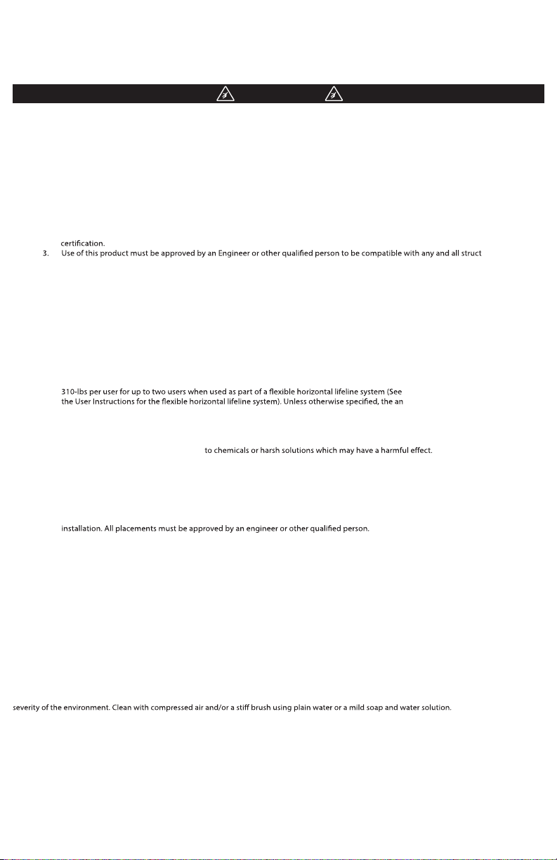
10k Hybrid Anchor
Zinc Plated Steel
Max Capacity:
(1) person 400-lbs
WARNING: All persons using this equipment must read,
understand and follow all instructions. Failure to do so may
result in serious injury or death.
COMPLIANCE: OSHA 1910.66 & 1926.502 ANSI Z359.1-07
Z359.7-11
(INSPECT BEFORE USE)
Tensile Strength (UTS): 10,000-lbf (44kN)
Maximum Capacity: See “Use Limitations”
Weight: 2.0-lbs (949g)
Regulatory Compliance
ANSI Z359.1-2007, ANSI Z359.7-2011
OSHA 1910.66 , 1926.502
Model: A510002
1-(888)-523-3371
2.25”ø
(57.15mm)
5.5”
(139.7mm)
3.0”
(76.2mm)
Compression Bushing: Polyethylene.
Retaining Bushing: Zinc Plated Steel.
Cone: Stainless Steel.
Spoons: Stainless Steel.
Compression
Bushing
Retaining
1.0”
(25.4mm)
Bushing
COMPONENT MATERIALS:
Bolt: Zinc Plated Steel.
Sleeve: Zinc Plated Steel.
Return Wire: Aircraft Cable.
Swivel: Zinc plated steel.
(15.88cm)
Cable
6-1/4”
Bolt
Sleeve
Spoon
Cone
Page 4
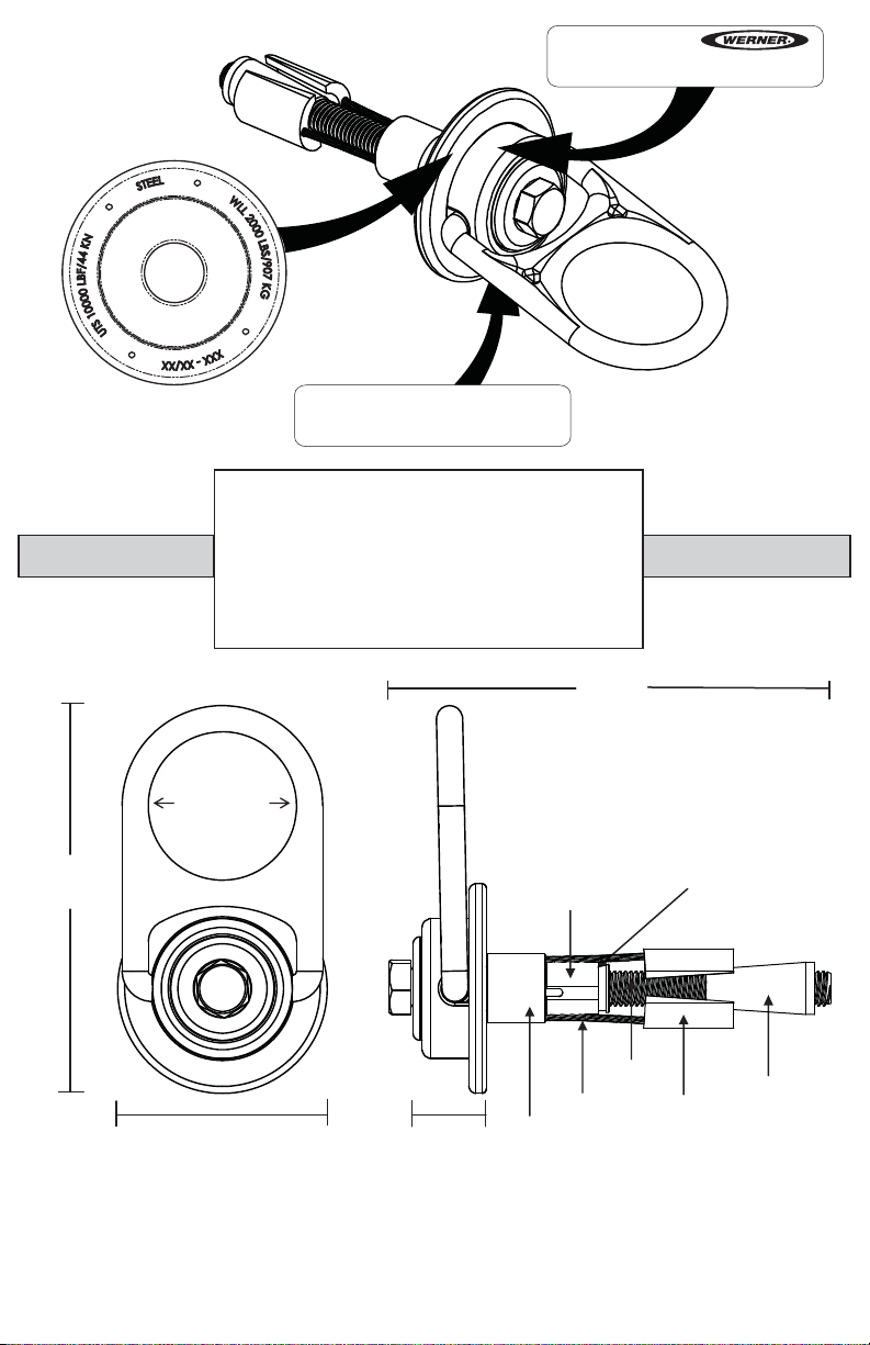
8.0”ø
180°
(203.2mm)
360°
LOADING CONDITIONS DIAGRAM
LOAD
LOAD
ACCEPTABLE ACCEPTABLE
LOAD
LOAD
IMPROPERACCEPTABLE
DRILLING :
1. Use a hammer drill (SDS), drill a 1” (25mm) diameter hole at least 5” (127mm) deep.
The drilled hole must be straight and perpendicular to the surface. Make sure the hole
is of uniform diameter and free of peaks and valleys on the inner wall. See diagram
below
2. Blow hole clean with compressed air.
3. Refer to the diagram below for hole location and requirements.
4. Always inspect the hole carefully when reusing a previously drilled hole.
Hole to Edge:
min
10”
(25.4cm)
rom any ed
f
e
g
6”min
(15.24cm)
Section View:
Drill 1ӯ
(2.54cm)
1”min
(2.54cm)
5” min
depth
(12.7cm)
Page 5
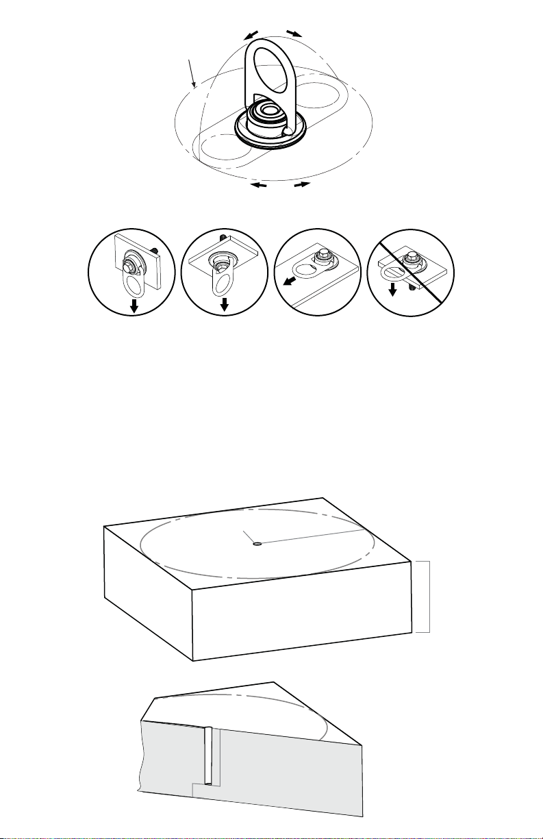
Check for kinked
or frayed cables.
Look for signs
of wear on
spoons.
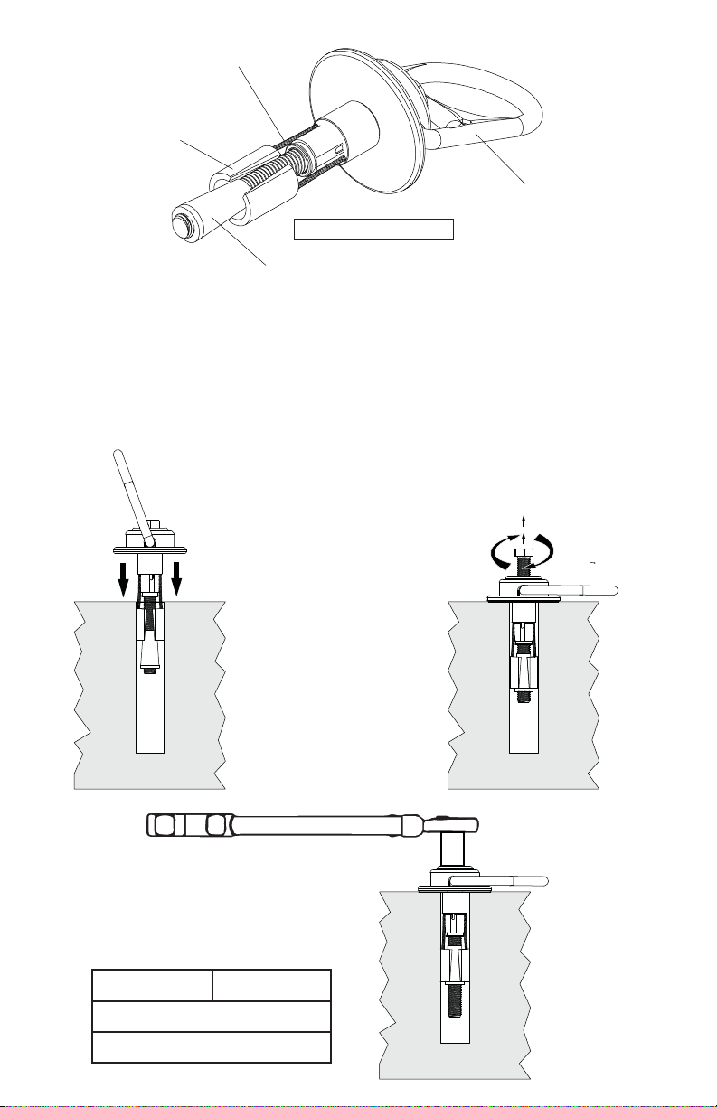
INSPECT BEFORE USE
Check for deformation
of cone.
INSTALLATION:
1. Before installing make sure the
cone is below the spoons. Insert
the anchor into hole so the base
plate rest at on the concrete
surface.
Drop In
Swivel should
move freely.
2. Pull up on the bolt while holding
swivel ush with the concrete.
Tighten the bolt by turning it
clockwise by hand until bolt is
fastened ush to swivel.
Step 1.
3. Use a torque wrench to set the
pretension on the bolt for the
loading situation required for
the application.
LOAD: BOLT TORQUE:
10,000-lbf
(44 kN)
5,000-lbf
(22 kN)
85-ft-lbs
(9.60 Nm)
30-ft-lbs
(3.38 Nm)
Step 3.
Pull Up
Bolt &
Step 2.
Twist
Clockwise
Page 6

REMOVAL:
1. Loosen bolt so that at least 3/4”
(1.9cm) of threads are exposed.
Unscrew
min of
3/4”
(1.9cm)
2. Use a hammer to tap down bolt
and disengage cone from the
spoons.
Step 1.
TAP!!!
Step 2.
3. Pull the anchor from the hole.
Pull UP
Step 3.
Page 7

May be used as a anchoring point for a leading
edge restraint system. Examples are of optional
anchoring point locations. The use of two anchors
is for illustration purposes only and
is not required for leading edge restraint systems
OPTIONAL
(ANCHOR POINTS)
WORK SURFACE
(ANCHOR POINT)
The concrete must be
3000-psi or higher and
fully cured. Installation
location to be approved
WORK SURFACE
Free fall distance (limit) must
not exceed 6’ ft (1.8 m). Refer
to connecting device
documentation for proper
usage and limitations.
MINIMUM CLEARANCE 3ft (1m)
DECK/FLOOR/GROUND LEVEL
All products subjected to fall arresting forces should be removed
from service immediately!
WARNING!!! SWING FALLS CAN OCCUR WHEN THE WORKER IS NOT DIRECTLY UNDER ANCHOR POINT.
PN200417 ©2013 Werner Co. 10/13
Page 8

INSPECTION AND MAINTAINANCE LOG
MODEL NUMBER:
DATE OF MANUFACTURE:
Dat e
s
m
muN tr
aP
reb
C
tnem
o
Inspector Name
Inspection:
conditions exist then inspections must be carried out more frequently. All inspection
results must be logged in the space provided above.
1.
2.
3. Inspect anchoring system for signs of damage or wear to spoons or cone.
4. Make sure the unit can rotate 360°
5. When reusing a previously drilled hole, inspect for for debris or wallowing.
6. Record inspection results in the space provide above.
unsafe conditions are found, proper disposal is required. The anchor connector
must be rendered unusable and then properly discarded.
Page 9

V1.2
MANUAL DE OPERACIÓN E INSTRUCCIONES
10.000-lbf (44kN.)
Anclaje giratorio híbrido, Modelo: A510002
¡IMPORTANTE!!!
TODAS LAS PERSONAS QUE UTILIZAN ESTE EQUIPO DEBEN LEER Y ENTENDER TODAS LAS
INSTRUCCIONES. NO HACERLO ASÍ PODRÍA RESULTAR EN LESIONES GRAVES O LA MUERTE.
LOS USUARIOS DEBEN FAMILIARIZARSE CON LAS NORMAS PERTINENTES QUE REGULAN
ESTE EQUIPO. TODAS LAS PERSONAS QUE UTILIZAN ESTE PRODUCTO DEBEN RECIBIR
INSTRUCCIONES APROPIADAS SOBRE CÓMO UTILIZAR ESTE DISPOSITIVO.
Page 10

Antes de utilizar este equipo, lea cuidadosamente este manual de instrucciones
Las Instrucciones para el Usuario siempre deben estar disponibles para el usuario y no deben removerse excepto por el usuario de este
equipo. Para conocer el uso apropiado, hable con su supervisor, vea las Instrucciones para el Usuario, o comuníquese con el fabricante.
ADVERTENCIA
Los sistemas de protección contra caídas y de rescate de emergencia que cumplen las normas ayudan a evitar lesiones graves durante la detención de
caída. Los usuarios y compradores de este equipo deben leer y entender las Instrucciones para el Usuario suministradas para el uso y cuidado correctos
de este producto. Todos los usuarios de este equipo deben entender las instrucciones, operación, limitaciones y consecuencias del uso inapropiado de
este equipo, y deben recibir capacitación apropiada antes de su uso según las normas OSHA 29 CFR 1910.66 y 1926.503 o las normas locales aplicables.
El uso incorrecto o no seguir las advertencias e instrucciones podrían resultar en lesiones personales graves o la muerte.
PROPÓSITO
El A510002 es un conector de ancladero diseñado para funcionar como interconexión entre el ancladero y un sistema de protección contra caídas, de
posicionamiento de trabajo, de acceso mediante cuerda, o de rescate, con el n de acoplar el sistema al ancladero. Cualquier referencia al “conector
de ancladero” en este manual incluye, y se aplica a, el A510002.
INSTRUCCIONES DE USO
1. Antes de utilizar un sistema personal de detención de caídas, el usuario debe recibir capacitación, según los requisitos de
OSHA 29 CFR 1910.66, sobre el uso seguro del sistema y sus componentes.
2. Sólo utilice con sistemas personales de detención o evitamiento de caídas que cumplan con ANSI/OSHA. El ancladero debe tener
una resistencia capaz de soportar una carga estática, aplicada en las direcciones permitidas por el sistema, de al menos
10.000 lbf (44 kN) en ausencia de certicación.
3. El uso de este producto debe ser aprobado, por un Ingeniero u otra persona calicada, indicando que es compatible con
cualquiera y todas las características estructurales y operativas de la ubicación de instalación seleccionada y del sistema que se
conectará a este anclaje. El uso inapropiado podría resultar en lesiones personales graves o la muerte.
4. El conector de ancladero se debe inspeccionar antes de cada uso en cuanto a desgaste, daño y otro deterioro. Si se encuentran
componentes defectuosos, el conector de ancladero debe retirarse inmediatamente del servicio, de acuerdo con los requisitos
de OSHA 29 CFR 1910.66 y 1926.502.
5. Antes de utilizar, se debe planear el sistema completo de protección contra caídas (incluyendo todos los componentes,
calculando el espacio libre de caída y la caída tipo columpio).
6. Se debe tener un plan de rescate, y los medios disponibles para implementarlo, que permita el rescate rápido de los usuarios en
caso de una caída, o que garantice que los usuarios pueden rescatarse ellos mismos.
7. Después que ocurra una caída, el conector de ancladero se debe retirar del servicio y destruirse inmediatamente.
LIMITACIONES DE USO
1. Capacidad máx.: Un (1) trabajador/usuario con peso máximo de 181 kg (400 lbs) cuando se utiliza como conector de ancladero
de punto único para un sistema personal de detención de caídas que limitará la fuerza de detención máxima del usuario a
1.800 lbf o menos. El conector de ancladero tiene una capacidad de 140 kg (310 lbs) por usuario para hasta dos usuarios cuando
se utiliza como parte de un sistema de cuerda salvavidas horizontal exible). A menos que se indique de otra manera, el conector
de ancladero tendrá una capacidad máxima de un (1) usuario de 310 lbs (140 kg) incluyendo la ropa, herramientas, etc. cuando
se utiliza como parte de un sistema de protección contra caídas que cumple la norma ANSI Z359.
2. El conector de ancladero se puede halar en cualquier dirección.
3. El conector de ancladero está diseñado para utilizarse en temperaturas que varían desde -40ºF a +130ºF (-40°C a +54°C).
4. No exponga el conector de ancladero a productos químicos o soluciones agresivas que pudieran tener un efecto perjudicial.
5. No altere ni modique de ninguna manera este producto.
6. Debe tenerse cuidado al utilizar cualquier componente de un sistema de protección contra caídas, de posicionamiento de
trabajo, de acceso mediante cuerda, o de rescate, cerca de máquinas en movimiento, peligros eléctricos, bordes losos, o
supercies abrasivas, ya que el contacto podría causar la falla del equipo, lesiones personales o la muerte.
7. No utilice ni instale el equipo sin capacitación apropiada por parte de una “persona competente” según lo denido por
OSHA 29 CFR 1926.32(f).
8. No remueva las etiquetas de este producto.
9. Se podrían aplicar requisitos y limitaciones adicionales dependiendo del tipo de anclaje y opción de sujeción utilizada para la
instalación. Todas las ubicaciones deben ser aprobadas por un ingeniero u otra persona calicada. El uso inapropiado
podría resultar en lesiones personales graves o la muerte.
LIMITACIONES DE COMPATIBILIDAD
Todos los conectores de ancladero sólo se deben acoplar a conectores compatibles. OSHA 29 CFR 1926.502 prohíbe enganchar los ganchos de cierre
resortado a ciertos objetos a menos que se cumplan dos requisitos: éste debe ser un gancho de cierre resortado del tipo con seguro, y éste debe
estar “diseñado para” realizar dicha conexión. “Diseñado para” signica que el fabricante del gancho de cierre resortado diseñó especícamente el
gancho de cierre resortado para utilizarse para conectar al equipo indicado. Las siguientes conexiones se deben evitar, porque éstas pueden resultar
en desenganche accidental* cuando se utiliza un gancho de cierre resortado sin seguro:
• Conexión directa de un gancho de cierre resortado a una cuerda salvavidas horizontal.
• Dos (o más) ganchos de cierre resortado conectados a un (1) anillo en “D”.
• Dos ganchos de cierre resortado conectados entre sí.
• Un gancho de cierre resortado conectado de regreso sobre su correa sujetadora integral.
• Un gancho de cierre resortado conectado a un lazo tejido o correa sujetadora tejida.
• Las dimensiones inapropiadas del anillo en “D”, barra de refuerzo u otro punto de conexión en relación con las dimensiones del gancho
de cierre resortado que podrían permitir que el jador del gancho de cierre resortado sea presionado por un movimiento giratorio del gancho
de cierre resortado.
*Desenganche accidental: Un proceso mediante el cual un gancho de cierre resortado o argolla rectangular metálica se desengancha accidentalmente de
otro conector u objeto al cual está acoplado. (ANSI Z359.1-2007)
MANTENIMIENTO, LIMPIEZA Y ALMACENAMIENTO
La limpieza periódica alargará la vida útil y funcionamiento apropiado del producto. La frecuencia de la limpieza debe ser determinada por la
inspección y según la severidad del medio ambiente. Limpie con aire comprimido y/o un cepillo de cerdas rígidas utilizando agua común o una
solución suave de agua y jabón. No utilice ningún producto químico corrosivo que pudiera dañar el producto. Limpie frotando todas las supercies
con un trapo seco limpio, y cuelgue para secar; o utilice aire comprimido. Cuando no están en uso, almacene los conectores de ancladero en un
ambiente fresco, seco y limpio, fuera de la luz solar directa y libre de elementos corrosivos u otros elementos dañinos.
Werner co. / 93 Werner Rd., Greenville, PA 16125 / 1-(888)-523-3371 / www.wernerco.com
Page 11

Anclaje híbrido 10k
Acero enchapado en zinc
Capacidad máx.:
(1) persona 181kg (400-lbs)
ADVERTENCIA: Todas las personas que utilizan este equipo
deben leer, entender y seguir todas las instrucciones. No
hacerlo así podría resultar en lesiones graves o la muerte.
(INSPECCIONE ANTES DE UTILIZAR).
CUMPLIMIENTO: OSHA 1910.66 Y 1926.502 ANSI Z359.1-2007
Z359.7-2011 CE 0321 / EN 795:1996 (+A1:2000) Clase B
Resistencia a la tracción estática (UTS):
10,000-lbf (44kN)
Capacidad máxima: See “Use Limitations”
Peso: 2.0-lbs (949g)
Cumplimiento de normas:
ANSI Z359.1-2007, ANSI Z359.7-2011
Modelo: A510002
1-(888)-523-3371
2.25”ø
(57.15mm)
5.5”
(139.7mm)
3.0”
(76.2mm)
COMPONENT MATERIALS:
Buje de compresión: Polietileno
buje de retención: Acero enchapado en zinc
Cono: Acero inoxidable
Cuchara: Acero inoxidable
1.0”
(25.4mm)
6-1/4”
(15.88cm)
Perno
Manguito
Cuchara
Cono
Buje de
compresión
Cable
Buje de
retención
Perno: Acero enchapado en zinc
Manguito: Acero enchapado en zinc
Cable: Cable de avión
Pieza giratoria: Acero enchapado en zinc
Page 12

8.0”ø
180°
(203.2mm)
360°
CONDICIONES DE CARGA DIAGRAMA
Carga
ADMISIBLE
Carga
ADMISIBLE
Carga
ADMISIBLE
Carga
INCORRECTO
TALADRADO:
1. Utilice un taladro percutor (SDS), taladre un oricio de 1” (25 mm) de diámetro con una profundi
dad mínima de 5” (127 mm).
El oricio taladrado debe ser recto y perpendicular a la supercie. Verique que el oricio tiene
un diámetro uniforme y está libre
de picos y valles en la pared interior. Vea el siguiente diagrama de distancia del oricio al borde
2. Limpie soplando el oricio con aire comprimido.
3. Consulte el siguiente diagrama de distancia del oricio al borde para ubicación del oricio y
requisitos.
4. Al reutilizar un oricio taladrado previamente, siempre inspeccione cuidadosamente el oricio.
Distancia del oricio al borde:
Oricio 1ӯ
(2.54cm)
10”
(25.4cm)
min. desde cualquier bor
e
d
6”min
(15.24cm)
Vista en sección:
1”min
(2.54cm)
5” de profundidad
min.
(12.7cm)
Page 13

Revise en busca de cables
retorcidos o deshilachados.
Busque indicios de
desgaste en las
cucharas.
INSPECCIONE ANTES DE UTILIZAR
Revise en busca de
deformación del cono.
INSTALACIÓN:
1. Antes de realizar la instalación, verique que el cono
está debajo de las cucharas según se muestra en el el
diagrama de instalación. Inserte el anclaje dentro del
oricio de modo que la placa de base quede apoyada
de manera plana sobre la supercie de concreto.
Inserte
Verique que la
pieza giratoria se
pueda mover
libremente.
2. Hale hacia arriba el perno mientras
sostiene la pieza giratoria a ras con el
concreto. Apriete el perno girándolo en
sentido horario con sus dedos hasta que
el perno quede atornillado todo el
recorrido a mano.
Hale hacia
arriba el
perno y
Gire en
sentido
horario
Paso 1.
3. Utilice una llave de torsión (llave
dinamométrica) para aplicar la
pretensión del perno para la situación
de carga requerida para la aplicación.
CARGA:
10,000-lbf
(44 kN)
5,000-lbf
(22 kN)
APRIETE DEL PERNO:
85 lbs-pie
(9.60 Nm)
30 lbs-pie
(3.38 Nm)
Paso 2.
Paso 3.
Page 14

Destornille
un mínimo de
REMOCIÓN:
1. Aoja el perno de modo que se
exponga una longitud mínima de 3/4”
(1.9 cm) de roscas.
3/4”
(1,9cm)
2. Utilice un martillo para golpear
hacia abajo el perno y desenganchar el
cono fuera de las cucharas.
¡GOLPEE
SUAVEMENTE!!!
Paso 2.
Paso 1.
3. El anclaje debe poderse halar hacia
afuera del oricio. Vea el diagrama de
remoción.
Hale hacia
arriba
Paso 3.
Page 15

Se puede utilizar como punto de anclaje para un sistema
de evitamiento de caídas de borde delantero. Ejemplos
son las ubicaciones de puntos de anclaje opcionales. El
uso de dos anclajes es sólo para propósitos de ilustración
y no se requieren para los sistemas de evitamiento de
caídas de borde delantero a menos que sea especicado
de otra manera por el fabricante).
OPCIONAL
(PUNTOS DE ANCLAJE)
SUPERFICIE DE TRABAJO
(PUNTO DE ANCLAJE)
El concreto debe tener una
resistencia de 3000 psi o
superior, y estar totalmente
curado. La ubicación de
instalación debe ser
aprobada por una persona
calicada.
SUPERFICIE DE TRABAJO
La distancia (límite) de caída libre no
debe superior a 6 pies (1,8 m).
Consulte los documentos del
dispositivo conector para conocer
el uso apropiado y limitaciones.
DISTANCIA MÍNIMA SOBRE EL SUELO: 3 pies (1 m)
NIVEL DE PLATAFORMA/PISO/SUELO
¡Todos los productos sometidos a fuerzas de detención de caída
deben retirarse del servicio inmediatamente
¡ADVERTENCIA!!! LAS CAÍDAS TIPO COLUMPIO PUEDEN OCURRIR CUANDO EL TRABAJADOR NO ESTÁ DIRECTAMENTE DEBAJO DEL PUNTO DE ANCLAJE.
PN200417 ©2013 Werner Co. 10/13
Page 16

REGISTRO DE INSPECCIÓN Y MANTENIMIENTO
NÚMERO DE MODELO:
FECHA DE FABRICACIÓN:
Número de pieza
Comentarios
Nombre del
inspector
Se debe realizar una inspección periódica ocial al menos anualmente. La inspección
debe ser realizada por una persona calicada diferente al usuario previsto. Si existen
condiciones climáticas severas, entonces las inspecciones se deben realizar más
frecuentemente. Todos los resultados de la inspección se deben registrar en el espacio
suministrado arriba.
1. Inspeccione la pieza giratoria para vericar que está a ras con la supercie de montaje.
2. Verique que las etiquetas están jadas a la unidad.
3. Inspeccione el sistema de anclaje en busca de señales de daño o desgaste de las
cucharas o el cono.
4. Verique que la unidad puede girar 360° y que el anillo en “D” puede girar de lado a lado.
5. Al reutilizar un oricio previamente taladrado, inspeccione en busca de residuos u oricio
desgastado (rodado).
6. Registre los resultados de la inspección en el espacio suministrado arriba.
*Si encuentra algún daño que pudiera afectar la resistencia o funcionamiento del dispositivo,
o condiciones inseguras, se requiere desechar apropiadamente el dispositivo. El conector de
ancladero se debe inutilizar y luego desechar de manera apropiada.
 Loading...