

Page 1
IMPORTANT!!!
ALL PERSONS USING THIS EQUIPMENT MUST READ AND UNDERSTAND ALL INSTRUCTIONS.
FAILURE TO DO SO MAY RESULT IN SERIOUS INJURY OR DEATH. USERS SHOULD BE FAMILIAR
WITH PERTINENT REGULATIONS GOVERNING THIS EQUIPMENT. ALL INDIVIDUALS WHO USE
THIS PRODUCT MUST BE PROPERLY INSTRUCTED ON HOW TO USE THIS DEVICE.
User Instructions must always be available to the user and are not to be removed except by the user of this equipment. For proper use, see
supervisor, User Instructions, or contact the manufacturer.
Compliant fall protection and emergency rescue systems help prevent serious injury during fall arrest. Users and purchasers of this
equipment must read and understand the User Instructions provided for correct use and care of this product. All users of this equipment
must understand the instructions, operation, limitations and consequences of improper use of this equipment and be properly trained
prior to use per OSHA 29 CFR 1910.66 and 1926.503 or applicable local standards. Misuse or failure to follow warnings and instructions
may result in serious personal injury or death.
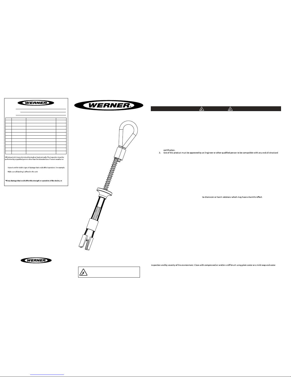
PURPOSE
The
A
510000
is an anchorage connector designed to function as an interface between the anchorage and a fall protection, work positioning,
rope access, or rescue system for the purpose of coupling the system to the anchorage. Any references to “anchorage connector” in this
manual include, and apply to, the
A
510000
.
USE INSTRUCTIONS
1. Before using a personal fall arrest system, user must be trained in accordance with the requirements of OSHA 29 CFR
1910.66 in the safe use of the system and its components.
2. Use only with ANSI/OSHA compliant personal fall arrest or restraint systems. The anchorage must have the strength capable
of supporting a static load, applied in the directions permitted by the system, of at least 5,000-lbf (22.2 kN) in the absence of
& operational characteristics of the selected installation location and system to be connected to this anchor. Improper use
may result in serious personal injury or death.
4. The anchorage connector must be inspected prior to each use for wear, damage, and other deterioration and defective
components must be immediately removed from service, in accordance with the requirements of OSHA 29 CFR
1910.66 and 1926.502.
5. The complete fall protection system must be planned (including all components, calculating fall clearance, and swing fall)
before using.
6. A rescue plan, and the means at hand to implement it, must be in place that provides the prompt rescue of users in the
event of a fall, or assures that users are able to rescue themselves.
7. After a fall occurs, anchorage connectors must be removed from service and destroyed immediately.
USE LIMITATIONS
1. The
anchorage connector
is designed for single user system, with a capacity up to 310 lb (181 kg) per
user including clothing, tools, etc. can be used with a flexible horizontal lifeline system that requires a 5,000-lbs anchor. See
anchorage requirements in the user instructions for the flexible horizontal lifeline system.
2. The
anchorage connector
may be loaded in any direction
3.
The Anchorage connector
is designed to be used in temperatures ranging from -40ºF to +130ºF (-40°C to +54°C).
4. Do not expose the
anchorage connector
5. Do not alter or modify this product in anyway.
6. Caution must be taken when using any component of a fall protection, work positioning, rope access, or rescue system near
moving machinery, electrical hazards, sharp edges, or abrasive surfaces, as contact may cause equipment failure, personal
injury, or death.
7. Do not use/install equipment without proper training by a “competent person” as defined by OSHA 29 CFR 1926.32(f).
8. Do not remove the labeling from this product.
9. Additional requirements and limitations may apply depending on anchorage type and fastening option utilized for
installation. Refer to the applicable section in this manual for further details. Improper use may result in serious personal
injury or death.
COMPATIBILITY LIMITATIONS
All Reusable Concrete Anchors must only be coupled to compatible connectors. OSHA 29 CFR 1926.502 prohibits snaphooks from being
engaged to certain objects unless two requirements are met: it must be a locking type snaphook, and it must be “designed for” making
such a connection. “Designed for” means that the manufacturer of the snaphook specifically designed the snaphook to be used to connect
to the equipment listed. The following connections must be avoided, because they can result in rollout* when a nonlocking snaphook is
used:
• Direct connection of a snaphook to horizontal lifeline.
• Two (or more) snaphooks connected to one D-ring.
• Two snaphooks connected to each other.
• A snaphook connected back on its integral lanyard.
• A snaphook connected to a webbing loop or webbing lanyard.
*Rollout: A process by which a snaphook or carabiner unintentionally disengages from another connector or object to which it is coupled.
(ANSI Z359.1-2007)
MAINTAINANCE, CLEANING AND STORAGE
Cleaning periodically will prolong the life and proper functioning of the product. The frequency of cleaning should be determined by
solution. Do not use any corrosive chemicals that could damage the product. Wipe all surfaces with a clean dry cloth and hang to dry, or use
compressed air. When not in use, store anchorage connectors in a cool, dry, clean environment, out of direct sunlight and free of corrosive or
other degrading elements.
WARNING
Inspection:
conditions exist then inspections must be carried out more frequently. All inspection
results must be logged in the space provided above.
1.
kinked or frayed cables.
2.
3. Check spoons and end termination operate smoothly with no metal burrs.
4. When reusing a previously drilled hole, inspect for for debris or wallowed out hole.
5. Record inspection results in the space provide above.
Part Number Comments Inspector Name
INSPECTION AND MAINTAINANCE LOG
unsafe conditions are found, proper disposal is required. Reusable Concrete
Anchor must be rendered unusable and then properly discarded.
MODEL NUMBER:
DATE OF MANUFACTURE:
SERIAL NUMBER:
Werner Co. Corporate Headquarters
93 Werner Road
Greenville, PA 16125
1(888)-523-3371
www.wernerco.com
Operations and Instruction Manual
ANSI Z359.1-2007 / OSHA 1926.502 & 1910.66 /
CE 0321 / EN 795:1996 (+A1:2000) Class B
Reusable Concrete Anchor
5,000-lbs / 22kN
Model: A510000
Assembled in USA
V1.3
Page 2
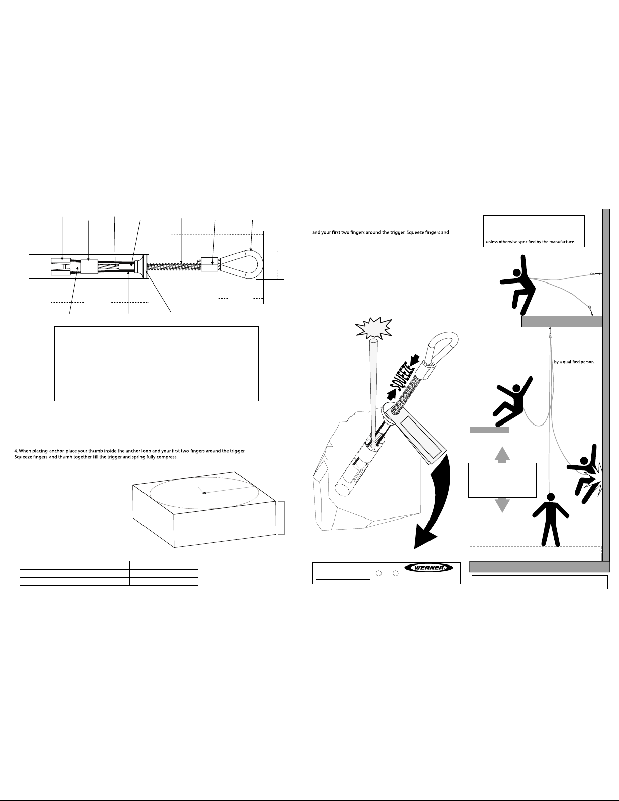
DRILLING & INSTALLATION INSTRUCTIONS:
1. Drill a 3/4” (20mm) diameter hole at least 3.5” (89mm) deep. The drilled hole must be straight and perpendicular to
the surface. Make sure the hole is of uniform diameter and free of peaks and valleys on the inner wall.
2. Blow hole clean with compressed air.
3. Always inspect the hole carefully when reusing a previously drilled hole.
4. Insert unit at least 3” (76mm) deep into hole and release the trigger. Do not force.
5. Set the unit with a slight tug on the anchor loop.
6. The stop sleeve must always be partially inserted into the hole.
All products subjected to fall arresting forces should be removed
from service immediately!
DECK/FLOOR/GROUND LEVEL
WORK SURFACE
(ANCHOR POINT)
MINIMUM CLEARANCE 3ft (1m)
WARNING!!! SWING FALLS CAN OCCUR WHEN THE WORKIER IS NOT DIRECTLY UNDER ANCHOR POINT.
Free fall distance (limit) must
not exceed 6’ ft (1.8 m).Free fall
distance (limit) must bnot exceed
6’ ft (1.8 m). Refer to connecting
device documentation for proper
usage and limitations
The concrete must be
3000-psi or higher and
fully cured. Installation
location to be approved
Performance:
Static tensile strength: 5000-lbf
(
22kN) minimum.
Maximum capacity: one worker with
max weight of
310-lbs when used as
a single point anchorage connector
for personal fall arrest or restraint
Dimensions:
Weight: 0.4-lbs (.18kg)
Length: 11.5” (293mm)
Diameter: 0.75” (20mm)
Regulatory compliance
Meets or exceeds ANSI Z359.1-2007 and OSHA
1926.502 CE 0321 / EN 795:1996 (+A1:2000) Class B
Component Materials:
Main Cable: Aircraft Cable. End Termination: Stainless Steel. Spoons: Stainless Steel.
Stop Sleeve: Stainless Steel. Trigger: Aluminum. Spring: Zinc Plated Steel. Swage: Zinc
Plated Copper. Return Wire: Aircraft Cable. Loop Cover: Polyurethane.
Spoon
Cleaning Bushing
Spring
Swage
Anchor Loop
Heavy Duty Return Wire
Stop Sleeve
End Termination
Trigger
1.25” (31mm)
3.0” (76mm)
5.0” (127mm)
11.5” (293mm)
Main Cable
2” (50.8mm)
REMOVAL INSTRUCTIONS:
1. When removing anchor, place your thumb inside the anchor loop
thumb together till the trigger and spring fully compress.
2. While squeezing the trigger pull the anchor out of the hole.
3. If the anchor becomes stuck, insert a punch, screwdriver or other
object into the hole until touches the top of the cleaning bushing.
4. Lightly tap with a hammer making sure the tool is touching the top
of the cleaning bushing while squeezing the trigger. (The cleaning
bushing should be easily visible at the edge of the hole).
5. If tool was required to remove the anchor inspect thoroughly for
damage after removal. If damage is found remove from service and
destroy immediately.
WORK SURFACE
May be used as a anchoring point for a leading
edge restraint system. Examples are of optional
anchoring point locations. The use of two anchors
is not required for leading edge restraint systems
OPTIONAL
(ANCHOR POINTS)
TAP!!!
DO NOT REMOVE
Stainless Steel, Aluminum, Zinc Plated Copper, 7x19 Aircraft Cable
WARNING!!!
ALL PERSONS USING THIS EQUIPMENT MUST READ AND UNDERSTAND ALL INSTRUCTIONS.
FAILURE TO DO SO MAY RESULT IN SERIOUS INJURY OR DEATH. USERS SHOULD BE FAMILIAR
WITH PERTINENT REGULATIONS GOVERNING THIS EQUIPMENT. ALL INDIVIDUALS WHO USE
THIS PRODUCT MUST BE PROPERLY INSTRUCTED ON HOW TO USE THIS DEVICE.
Compliance: OSHA 1926.502 & 1910.66 / ANSI Z359.1
CE 0321 / EN 795:1996 (+A1:2000) Class B
DO NOT REMOVE
WARNING LABEL!
(A)”
drill 3/4ӯ
min from any edge
(B)”
HOLE DRILLING REQUIRMENT CHART
(A)” Minimum distance from edge/corner (B)” Concrete thickness
6” in. (15.3 cm)
12” in. (30.5 cm)
12” in. (30.5 cm)
5” in. (12.7 cm)
DO NOT REMOVE
Max Capacity 310-lbs
Reusable Concrete Anchor
Model: A510000
1-(888)-523-3371
Stainless Steel, Aluminum, Zinc Plated Copper, 7x19 Aircraft Cable
WARNING!!!
ALL PERSONS USING THIS EQUIPMENT MUST READ AND UNDERSTAND ALL INSTRUCTIONS.
FAILURE TO DO SO MAY RESULT IN SERIOUS INJURY OR DEATH. USERS SHOULD BE FAMILIAR
WITH PERTINENT REGULATIONS GOVERNING THIS EQUIPMENT. ALL INDIVIDUALS WHO USE
THIS PRODUCT MUST BE PROPERLY INSTRUCTED ON HOW TO USE THIS DEVICE.
Compliance: OSHA 1926.502 & 1910.66 / ANSI Z359.1
CE 0321 / EN 795:1996 (+A1:2000) Class B
RB5-068 / 01/2013
INSPECT BEFORE USE
 Loading...