

Page 1
FALL PROTECTION
PROTECCIÓN CONTRA CAÍDAS
USER INSTRUCTIONS
INSTRUCCIONES PARA EL USUARIO
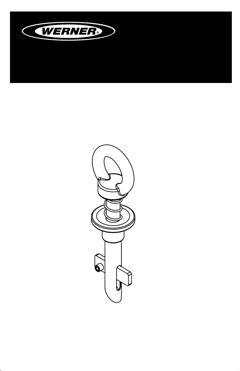
BUILDERS GRIP ANCHOR
Complies with ANSI Z359.1-2007, OSHA 1910 and 1926 requirements.
ANCLAJE DE AGARRE PARA CONSTRUCTORES
Cumple con las normas ANSI Z359.1-2007, OSHA 1910 y 1926.
(This manual applies to Builders Grip Anchor A420000.)
(Este manual aplica al Anclaje de Agarre para Constructores A420000.)
Werner Fall Protection 724-588-2000
93 Werner Rd. 888-523-3371 toll free/ llamada gratuita
Greenville, PA 16125 888-456-8458 fax
Page 2
CAUTION!
If use of fall protection equipment is necessary then the work
environment is dangerous and potentially deadly. Werner Company
products are designed to eliminate as much of the hazard as possible
but can do that ONLY if they are used correctly. Use this equipment as
it was designed to be used, after appropriate training, under the direct
supervision of a competent person, according to the instructions
provided, and in accordance with OSHA and local safety regulations.
User MUST read and understand all cautions and instructions. Failure
to heed these guidelines could result in injury or even death. Please,
WORK SAFE! WORK SMART!
ENGLISH
Page 2
Page 3

BUILDERS GRIP ANCHOR
USER INSTRUCTIONS
Contents
I. BEFORE USING THE BUILDERS GRIP ANCHOR .......................................... 4
a. Inspect ......................................................................................................................4
b. Compatibility ............................................................................................................5
c. Fall Protection Plan ..................................................................................................5
d. Training .....................................................................................................................8
II. BUILDERS GRIP ANCHOR INSTALLATION AND USE .................................. 8
a. Making a Connection ...............................................................................................8
b. Anchorage Strength ..............................................................................................10
c. Connector ...............................................................................................................10
d. Body Support .........................................................................................................11
e. Mounting Locations ...............................................................................................11
III. USE WARNINGS, RESTRICTIONS AND CAUTIONS ................................... 13
a. Purpose ..................................................................................................................13
b. Rated Capacity .......................................................................................................13
c. Dimensions .............................................................................................................13
d. Limitations..............................................................................................................14
e. Requirements .........................................................................................................14
IV. LABELS/IDENTIFICATION/INSPECTION RECORDS .................................. 15
V. EQUIPMENT RECORDS ................................................................................16
VI. INSPECTION RECORDS .............................................................................. 16
ENGLISH
Page 3
Page 4
Warning:
This product is just one part of a personal fall arrest system. It must
be matched correctly with other components to form a complete and
functional system. The user must understand the function of each of
these components and follow the manufacturer’s instructions for use
for each. The user must be provided these instructions, should read
and follow them, and consult the competent person who will supervise
his work if he has any questions about any part of the instructions.
The employer must provide training in the proper use, inspection, and
maintenance of all components in the system, and these instructions
can be used as part of that training. The equipment should be used
ONLY in accordance with these instructions, local ordinances and
codes, the applicable OSHA and ANSI standards, and the employer’s
safety plan. Alterations or misuse of this product or failure to follow
instructions may result in serious injury or death.
IF YOU HAVE ANY QUESTIONS ABOUT ANYTHING IN THESE
INSTRUCTIONS, THE EQUIPMENT, OR PROPER USE OF THE
EQUIPMENT, CONTACT WERNER CO. FOR MORE INFORMATION.
I. Before Using the Builders Grip Anchor
Before using this equipment the user should take certain steps to ensure
that it is in suitable condition and safe for use. Users must read and
understand these instructions. It is the employer’s obligation to ensure
that all users have been trained in safe work procedures as well as in the
use and limitations of fall protection equipment. All users should be aware
of and comply with all applicable OSHA, ANSI and local or regional
regulations concerning fall protection equipment and its use.
a. Inspect
Examine all equipment thoroughly, daily before use by the user,
and periodically by a competent person who is not the user.
1. Ensure that the Builders Grip Anchor is free from rust, corrosion
and any damage. Clean with warm soapy solution to prevent
damaging the Builders Grip Anchor or structure.
2. Inspect the Builders Grip Anchor to ensure there are no cracks,
dents or marks on the anchorage.
ENGLISH
Page 4
3. Inspect the Spring Loaded Blade. Inspect for damage or
corrosion. Make sure the device operates freely and is void of
obstructions.
Page 5

BUILDERS GRIP ANCHOR
USER INSTRUCTIONS
4. Make sure labels are attached to the Builders Grip Anchor and
are legible.
5. Record the inspection date and results in the Inspection and
Maintenance Log
6. If inspection reveals a defective condition or abnormalities in
any of these areas, remove unit from service immediately. A
competent person should be consulted to determine if that item
is safe for continued use or if it should be destroyed.
IMPORTANT: If this equipment has been subjected to forces
resulting from the arrest of a fall, it must be immediately removed
from service.
b. Compatibility
Werner Co. equipment is designed for use with Werner Co. approved
components and subsystems only. Substitutions or replacements
made with non-approved components or subsystems may
jeopardize compatibility of equipment and may affect the safety and
reliability of the complete system.
Connectors are considered to be compatible with connecting
elements when they have been designed to work together in
such a way that their sizes and shapes do not cause their gate
mechanisms to inadvertently open regardless of how they become
oriented. Contact Werner Co. if you have any questions about
compatibility. Connectors (hooks, carabiners, and D-rings) must be
capable of supporting at least 5,000 lbs. (22.2kN). Connectors must
be compatible with the anchorage or other system components.
Do not use equipment that is not compatible. Non-compatible
connectors may unintentionally disengage. See inappropriate
connections. Connectors must be compatible in size, shape, and
strength. Self locking snap hooks and carabiners are required by
ANSI Z359 and OSHA.
c. Fall Protection Plan
Plan your fall arrest or restraint system before starting your work.
Take into consideration all factors affecting your safety at any
time during use. The following list gives some important points to
consider when planning your system:
Page 5
ENGLISH
Page 6
1. ANCHORAGE: Select a rigid anchorage point that is capable of
supporting the required loads. See section II.b. The anchorage
location must be carefully selected to reduce possible free fall
and swing fall hazards and to avoid striking an object during
a fall. For restraint systems the anchorage must be located
such that no vertical free fall is possible. For fall arrest systems
OSHA requires the anchorage be independent of the means
suspending or supporting the user.
2. FREE FALL: Do not work above the anchorage level, increased
fall distance will result. Personal fall arrest systems must be
rigged such that the potential free fall is never greater than six
feet. Restraint systems must be rigged such that there is no
possible vertical free fall.
3. FALL ARREST FORCES: The assembled fall arrest system
must keep fall arrest
forces below 1,800 lbs.
when used with a full body
harness. Do not use a
Anchorages
SWING FALL
HAZARD
body belt for fall arrest.
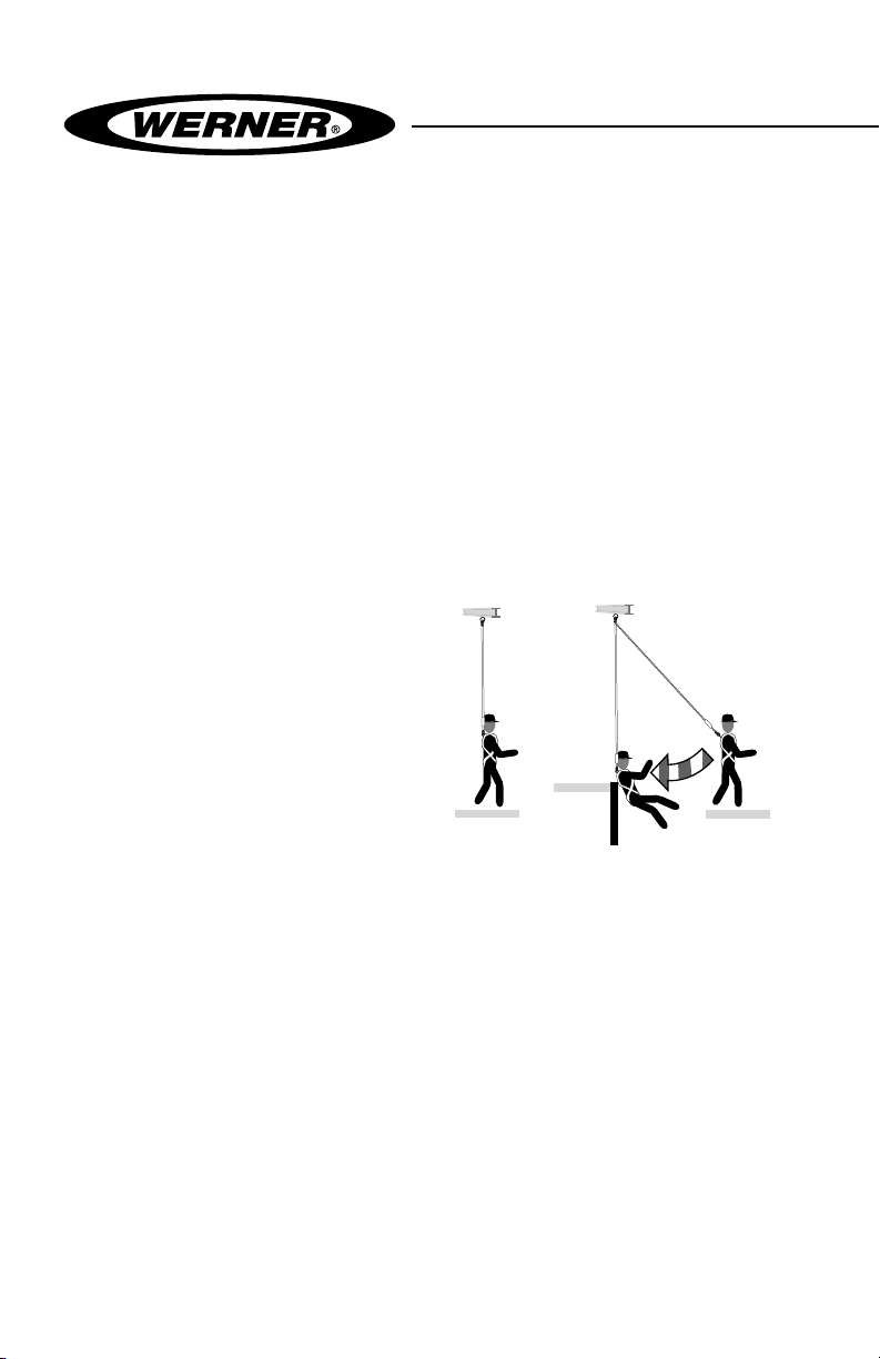
4. SWING FALLS: Swing
falls occur when the
anchorage point is not
directly above the point
where a fall occurs. The
force of striking an object
CorrectIncorrect
in a swing fall may cause serious injury or death. Minimize swing
falls by working as close to the anchorage point as possible.
Do not permit a swing fall if injury could occur. Swing falls
will signicantly increase the clearance required when a selfretracting lifeline or other variable length connecting subsystem
is used.
5. FALL CLEARANCE: Make certain enough clearance exists
in your fall path to prevent striking an object. The amount of
clearance needed is dependent upon the type of connecting
subsystem used and anchorage location. See Fall distance
charts for shock absorbing lanyards or Fall distance for selfretracting lifelines for estimating fall clearance.
ENGLISH
Page 6
Page 7
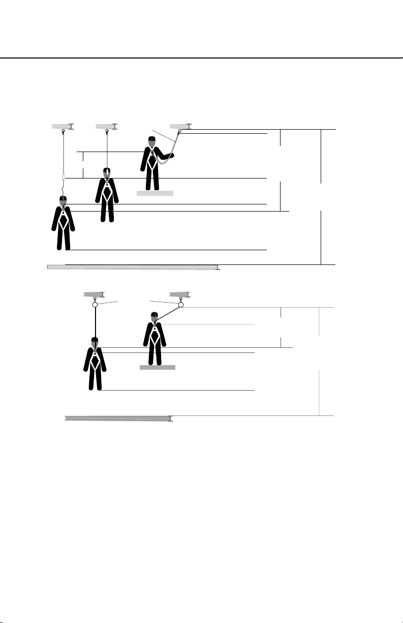
BUILDERS GRIP ANCHOR
Total Fall
Distance
(Free Fall +
Deceleration)
Free Fall
Working Level
Lower Level or Obstruction
Energy
Absorbing
Lanyard
Length of Anchorage Connector
6 ft.
Length of Lanyard
11 ft.
4 ft.
Deceleration Free Fall Distance
2 ft.
Safety Factor
1 ft. Harness Stretch
5 ft.
To Worker’s Back D-Ring
Total Estimated
Fall Distance
18 ft.
Fall distance for shock absorbing lanyards
Fall distance for self-retracting lifeline
Self Retracting
Lifeline
Working Level
Bottom of Retractable Lifeline
2 ft.
Maximum Free Fall
2.5 ft.
Maximum Deceleration
1 ft. Harness Stretch
5 ft.
To Worker’s Back D-Ring
USER INSTRUCTIONS
Maximum Arrest
Distance (per ANSI)
4.5 ft.
Total Estimated
Fall Distance
12.5 ft.
2 ft.
Lower Level or Obstruction
Safety Factor
6. RESCUE: Should a fall occur, the user (employer) must have a
rescue plan. If a worker falls and is forced to remain suspended
for any length of time, physical damage to the body or even
death can result. For this reason Werner, OSHA, ANSI and
most local regulations require that a rescue plan and the means
to implement the rescue plan are in place before use of this
equipment.
7. AFTER A FALL: Any equipment which has been subjected
to the force of arresting a fall must be removed from service
immediately.
ENGLISH
Page 7
Page 8
Warning:
Never connect more than one personal fall arrest or restraint system
to a single Builders Grip Anchor.
Warning:
Follow manufacturer’s instructions for associated equipment used in
your fall protection or restraint system
d. Training
OSHA, ANSI, and most local ordinances require that workers using
this product receive adequate training before use of this product.
These instructions and their entire contents should be a part of that
training.
II. Builders Grip Anchor Installation and Use
Warning:
Do not alter or intentionally misuse this equipment. Consult with
Werner Co. if using this equipment with components or subsystems
other than those described in this manual. Some subsystem and
component combinations may interfere with the operation of this
equipment. Use caution when using this equipment around moving
machinery, electrical hazards, chemical hazards, and sharp edges.
Warning:
Do not use this device if you are unable to tolerate the impact of
a fall arrest. Age and tness can seriously affect your ability to
withstand a fall. Pregnant women and minors must not use this
equipment.
a. Making Connections
1. Only use self-locking snap hooks and carabiners with this
equipment. Only use connectors that are suitable to each
application. Ensure all connections are compatible in size, shape
and strength. Do not use equipment that is not compatible.
Ensure all connectors are fully closed and locked.
PROPER CONNECTION
ENGLISH
Page 8
2. Werner Co. connectors (snap
hooks and carabiners) are
designed to be used only as
specied in each product’s
user’s instructions. See
inappropriate connections.
Page 9
BUILDERS GRIP ANCHOR
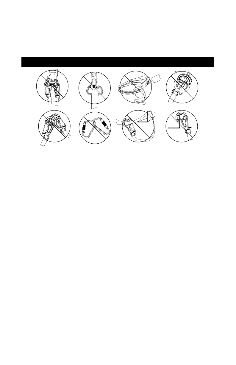
INAPPROPRIATE CONNECTIONS
A. B.
NO! NO! NO! NO!
D. E. F.
Werner Co. snap hooks and carabiners should NOT be
connected:
i. to a D-ring to which another connector is attached.
ii. in a manner that would result in a load on the gate. If the
connecting element that a snaphook or carabiner attaches
to is undersized or irregular in shape, a situation could occur
where the connecting element applies a force to the gate of
the snaphook or carabiner. This force may cause the gate
(of either a self-locking or a non-locking snaphook) to open,
allowing the snaphook or carabiner to disengage from the
connecting point.
NOTE: Large throat opening snap hooks should not be
connected to standard size D-rings or similar objects which
will result in a load on the gate if the hook or D-ring twists
or rotates. Large throat snap hooks are designed for use on
xed structural elements such as rebar or cross members
that are not shaped in a way that can capture the gate of
the hook.
iii. in a false engagement, where features that protrude from
the snap hook or carabiner catch on the anchor and without
visual conrmation seems to be fully engaged to the anchor
point.
iv. to each other.
v. directly to webbing or rope lanyard or tie-back (unless
the manufacturer’s instructions for both the lanyard and
connector specically allow such a connection).
USER INSTRUCTIONS
C.
NO!NO!NO!NO!
ENGLISH
Page 9
Page 10
vi. to any object which is shaped or dimensioned such that the
snap hook or carabiner will not close and lock, or that roll-
out could occur.
3. When using an energy-absorbing lanyard, connect the energy
absorber “pack” end to the harness.
b. Anchorage Strength
Depending on the application, the structure to which the D-Bolt is
installed must meet strengths as given below:
1. FALL ARREST: Anchorages selected for personal fall arrest
systems (PFAS) shall have a strength capable of sustaining
static loads, applied in the directions permitted by the PFAS, of
at least; (A) 3,600 lbs. (16kN) when certication exists (see ANSI
Z359.1 for certication denition), or (B) 5,000 lbs. (22kN) in the
absence of certication. When more than one PFAS is attached
to an anchorage, the anchorage strengths set forth in (A) and
(B) above shall be multiplied by the number of personal fall
arrest systems attached to the anchorage.Per OSHA 1926.500
and 1910.66; Anchorages used for attachment of PFAS shall
be independent of any anchorage being used to support or
suspend platforms, and capable of supporting at least 5,000 lbs.
(22kN) per user attached, or be designed, installed, and used as
part of a complete PFAS which maintains a safety factory of at
least two, and is supervised by a qualied person.
2. RESTRAINT: Anchors selected for restraint applications must
be attached to a structure capable of sustaining a static load
of at least 3,000 lbs. applied in any direction permitted by the
restraint system when in use. Each anchor installation must be
independently capable of sustaining this load. When more than
one restraint system is attached to an anchorage, the strengths
stated above must be multiplied by the number of restraint
system attached to the anchorage.
Warning:
Restraint anchorages may only be used where there is no possible
vertical free fall. Restraint anchorages do not have sufficient strength
for fall arrest. Do not connect personal fall arrest systems to restraint
anchorages.
3. WORK POSITIONING: The structure to which the anchor point
ENGLISH
is attached must sustain static loads applied in the directions
permitted by the work positioning system of at least 3,000 lbs., or
Page 10
Page 11

BUILDERS GRIP ANCHOR
Squeeze to
Deactivate Lock
Release to
Activate Lock
USER INSTRUCTIONS
twice the potential impact load, whichever is greater. When more
than one work positioning system is attached to an anchorage,
the strengths stated above must be multiplied by the number of
work positioning systems attached to the anchorage.
c. Connector
For fall arrest systems Werner Co. recommends using energy
absorbing lanyards incorporating self-locking snap hooks or selfretracting lifelines. Lanyards labeled ANSI A10.14 Type II must
not be used for fall arrest applications. All lanyards must have a
minimum breaking strength of 5,000 lbs.
NOTE: Applications such as working near high voltage may require
special lifeline materials, consult Werner Co. before using such
lifelines.
d. Body Support
The recommended body support for fall arrest applications is a full
body harness, for restraint applications a body belt may be used.
e. Using the Builders Grip Anchor:
1. Do not use the Builders Grip Anchor in a horizontal fashion.
The device is to be used overhead and in a vertical position.
Other installation applications must be approved by Werner Co.
2. The Builders Grip Anchor may be attached to the structure by
pulling on the spring loaded trigger component.
3. When pulling on the spring loaded
trigger, the blade rotates to a
parallel position to the stem. The
device is then inserted through a
bolt hole in the range of .75 inches
to 1.25 inches.
4. Ensure that the spring loaded
blade returns to its original
perpendicular position after the
blade has cleared the hole in the
steel work.
Page 11
ENGLISH
Page 12

III. Use Warnings, Restrictions and Cautions
a. Purpose
Werner Co. Builders Grip Anchor provide a permanent or semipermanent anchorage point for personal fall arrest systems where
anchorage on a surface is required. The Builders Grip Anchor’s
connection loop will accommodate all of Werner Co. snaphooks
and carabiners.
b. Rated Capacity
Capacity: 310 lbs. This equipment is designed for use by persons
with a combined weight (person, clothing, tools, etc.) of no more
than 310 lbs. NOTE: No more than one person may be attached to
this device. See d. Limitations.
c. Dimensions
R1.25"
Ø1.40"
ENGLISH
Page 12
1.50"
2.20" Ø0.75"
Page 13

BUILDERS GRIP ANCHOR
USER INSTRUCTIONS
d. Limitations
The following application limitations must be recognized and
considered before using this product:
1. FREE FALL: Restraint systems must be rigged such that there
is no possible vertical free fall. Personal fall arrest systems must
be rigged in such a way to limit the free fall to six feet (ANSI
Z359.1). See associated connecting subsystem manufacturer’s
instructions for further information.
2. FALL CLEARANCE: Make certain that enough clearance exists
in your fall path to prevent striking an object. The amount of
clearance required is dependent upon the type of connecting
subsystem used (lanyard, lifeline), the anchorage location, and
the amount of stretch in the lifeline. See section I.c for more
information on determining fall clearance.
3. ENVIRONMENTAL HAZARDS: Use of this equipment in areas
with environmental hazards may require additional precautions
to prevent injury to the user or damage to the equipment.
Hazards may include, but are not limited to: heat, chemicals,
corrosive environments, high voltage power lines, gases, moving
machinery, and sharp edges.
4. TRAINING: This equipment is to be used by persons who have
been properly trained in its correct application and use.
e. Requirements
Refer to applicable local, state, and federal (OSHA) requirements
governing this equipment for more information on anchorages
and associated system components, including; ANSI Z359.1, and
OSHA 1910.66, appendix C.
IV. Labels/Identication/Inspection Records
a. All products should be inspected by the user thoroughly before
each use. Additional inspections by a competent person other than
the user should be conducted at least annually. That interval should
be shortened any time the product is used in a harsh environment
or is exposed to conditions such as chemicals, abrasion, heat or
any other factor that could affect the strength of any of the materials
or components.
ENGLISH
Page 13
Page 14

b. This manual should always accompany the product, or be on le
with the employer for access when needed. Record the identication
details for the anchor and record the inspections in the inspection
log, on page 16. It is important to keep this log current, complete,
and available as needed.
ENGLISH
Page 14
Page 15

BUILDERS GRIP ANCHOR
USER INSTRUCTIONS
Id label
Warning label
Page 15
ENGLISH
Page 16

V. Equipment Record
PART NUMBER
SERIAL NUMBER
DATE
MANUFACTURED
PURCHASE DATE
ASSIGNED TO
SPECIFICATIONS
Werner Builders Grip Anchor
Certied to meet ANSI Z359.1-2007, and OSHA 1910 and 1926 standards
and regulations for the subsystem components of a complete personal
fall arrest system.
VI. Inspection Record
INSPECTION RECORD
DAT E INSPECTOR PASS/FAILDAT E INSPECTOR PASS/FAIL
ENGLISH
Page 16
Page 17

ANCLAJE DE AGARRE PARA CONSTRUCTORES
INSTRUCCIONES PARA EL USUARIO
¡PRECAUCIÓN!
Si el uso de equipos de protección contra caídas es necesario, entonces el
ambiente de trabajo es peligroso y potencialmente mortal. Los productos
Werner Company están diseñados para eliminar peligros tanto como sea
posible, pero SÓLO si estos productos se utilizan correctamente. Utilice este
equipo tal como fue diseñado para usarse, después de una capacitación
apropiada, bajo la supervisión directa de una persona calicada, de acuerdo
con las instrucciones suministradas, y de acuerdo con las regulaciones OSHA
y las regulaciones de seguridad locales. El usuario DEBE leer y entender todas
las precauciones e instrucciones. No tener en cuenta estas directrices podría
resultar en lesiones o incluso la muerte. Por favor, ¡TRABAJE DE MANERA
SEGURA! ¡TRABAJE DE MANERA INTELIGENTE!
Página 17
ESPAÑOL
Page 18

Contenido
I. ANTES DE UTILIZAR EL ANCLAJE DE AGARRE PARA CONSTRUCTORES ............... 19
a. Inspeccione .................................................................................................................................. 19
b. Compatibilidad ............................................................................................................................. 20
c. Plan de protección contra caídas ...............................................................................................20
d. Capacitación.................................................................................................................................23
II. INSTALACIÓN Y USO DEL ANCLAJE DE AGARRE PARA CONSTRUCTORES ...........23
a. Realización de una conexión ......................................................................................................23
b. Resistencia del anclaje ................................................................................................................25
c. Conector ....................................................................................................................................... 26
d. Soporte del cuerpo ...................................................................................................................... 26
e. Ubicaciones de montaje .............................................................................................................. 26
III. TENGA EN CUENTA LAS ADVERTENCIAS, RESTRICCIONES Y PRECAUCIONES ....27
a. Propósito.......................................................................................................................................27
b. Capacidad nominal ...................................................................................................................... 27
c. Dimensiones ................................................................................................................................. 27
d. Limitaciones ................................................................................................................................. 28
e. Requisitos ..................................................................................................................................... 28
IV. ETIQUETAS/IDENTIFICACIÓN/REGISTROS DE INSPECCIÓN .....................................28
V. REGISTROS DE EQUIPOS ...............................................................................................31
VI. REGISTROS DE INSPECCIÓN ........................................................................................31
ESPAÑOL
Página 18
Page 19

ANCLAJE DE AGARRE PARA CONSTRUCTORES
INSTRUCCIONES PARA EL USUARIO
Advertencia:
Este producto es sólo una parte de un sistema personal de detención de
caídas. Éste debe combinarse correctamente con otros componentes para
conformar un sistema completo y funcional. El usuario debe entender la
función de cada uno de estos componentes y seguir las instrucciones del
fabricante para el uso de cada componente. El usuario debe recibir estas
instrucciones, debe leerlas y seguirlas, y consultar a la persona calicada que
supervisará su trabajo si tiene alguna pregunta acerca de cualquier parte de
las instrucciones. El empleador debe proporcionar capacitación sobre el uso
apropiado, inspección y mantenimiento de todos los componentes del sistema,
y estas instrucciones pueden utilizarse como parte de esa capacitación. El
equipo SÓLO debe utilizarse de acuerdo con estas instrucciones, ordenanzas
y códigos locales, las normas OSHA y ANSI aplicables, y el plan de seguridad
del empleador. Las alteraciones o uso incorrecto de este producto, o no
seguir estas instrucciones, podría resultar en lesiones graves o la muerte.
SI USTED TIENE ALGUNA PREGUNTA ACERCA DE ALGO DE ESTAS
INSTRUCCIONES, EL EQUIPO O EL USO APROPIADO DEL EQUIPO,
COMUNÍQUESE CON WERNER CO. PARA OBTENER MÁS INFORMACIÓN.
I. Antes de utilizar el anclaje de agarre para constructores
Antes de utilizar este equipo, el usuario debe realizar ciertos pasos para
garantizar que éste está en condiciones apropiadas y es seguro para su uso. Los
usuarios deben leer y entender estas instrucciones. Es obligación del empleador
garantizar que todos los usuarios hayan recibido capacitación sobre los
procedimientos de trabajo seguros y también sobre el uso y limitaciones de los
equipos de protección contra caídas. Todos los usuarios deben estar informados
acerca de y cumplir todas las normas OSHA, ANSI aplicables y las normas
locales o regionales relacionadas con los equipos de protección contra caídas y
su uso.
a. Inspeccione
Todo el equipo debe ser examinado completamente, diariamente antes
del uso, por parte del usuario; y periódicamente por parte de una persona
calicada que no sea el usuario.
1. Verique que el anclaje de agarre para constructores no tiene óxido,
corrosión ni ningún daño. Limpie con una solución jabonosa tibia para
evitar dañar el anclaje de agarre para constructores o la estructura.
2. Inspeccione el anclaje de agarre para constructores para garantizar
que no hay grietas, abolladuras o marcas en el anclaje.
3. Inspeccione la hoja accionada por resorte. Inspeccione en busca de
daño o corrosión. Verique que el dispositivo funciona libremente y que
no tiene obstrucciones.
ESPAÑOL
Página 19
Page 20

4. Verique que las etiquetas están sujetadas al anclaje de agarre para
constructores y que están legibles.
5. Registre la fecha y resultados de la inspección en el registro de
inspección y mantenimiento.
6. Si la inspección revela una condición defectuosa o anormalidades en
cualquiera de estas áreas, retire inmediatamente del servicio la unidad.
Debe consultarse a una persona capacitada para determinar si ese
elemento es seguro para uso continuado o si debe destruirse.
IMPORTANTE: Si este equipo ha sido sometido a las fuerzas resultantes
de una detención de caída, éste debe retirarse inmediatamente del
servicio.
b. Compatibilidad
Los equipos Werner Co. están diseñados para uso sólo con componentes
y subsistemas aprobados por Werner Co. Las sustituciones o reemplazos
realizados con componentes o subsistemas no aprobados podrían
arriesgar la compatibilidad del equipo y podrían afectar la seguridad y
conabilidad del sistema completo.
Los conectores se consideran compatibles con los elementos conectivos
cuando éstos han sido diseñados para trabajar en conjunto de tal manera
que sus tamaños y formas no causen que sus mecanismos de cierre
se abran inadvertidamente sin importar la manera como se orienten.
Comuníquese con Werner Co. si usted tiene alguna pregunta acerca
de la compatibilidad. Los conectores (ganchos, argollas rectangulares
metálicas y anillos en ‘D’) deben ser capaces de soportar 5.000 lbs.
(22.2kN). Los conectores deben ser compatibles con el ancladero u otros
componentes del sistema. No utilice equipos que no sean compatibles.
Los conectores no compatibles podrían desengancharse accidentalmente.
Vea las conexiones inapropiadas. Los conectores deben ser compatibles
en tamaño, forma y resistencia. Las normas ANSI Z359 y OSHA requieren
argollas rectangulares metálicas y ganchos de cierre resortado autoasegurables.
c. Plan de protección contra caídas
Planee su sistema de detención o evitamiento de caídas antes de iniciar
su trabajo. Tenga en cuenta todos los factores que afectan su seguridad en
cualquier momento durante el uso. La siguiente lista proporciona algunos
puntos importantes que deben considerarse al planear su sistema:
ESPAÑOL
Página 20
Page 21

ANCLAJE DE AGARRE PARA CONSTRUCTORES
INSTRUCCIONES PARA EL USUARIO
1. ANCLADERO: Seleccione un punto de anclaje rígido que sea capaz
de soportar las cargas requeridas. Vea la sección II.b. La ubicación del
anclaje debe seleccionarse cuidadosamente para reducir la posibilidad
de peligros por caída libre o por caída tipo columpio y para evitar
golpear un objeto durante una caída. Para los sistemas de evitamiento
de caídas, el anclaje debe ubicarse de modo que no sea posible
una caída libre vertical. Para los sistemas de detención de caídas,
OSHA exige que el anclaje sea independiente de los elementos que
suspenden o soportan el usuario.
2. CAÍDA LIBRE: No trabaje encima del nivel del anclaje porque existirá
una mayor distancia de caída. Los sistemas personales de detención de
caídas deben instalarse de modo que la posible caída libre nunca sea
superior a 1.83 m (6 pies). Deben instalarse sistemas de evitamiento de
caídas de modo que no haya posibilidad de caídas libres verticales.
3. FUERZAS DE DETENCIÓN DE CAÍDAS: El sistema de detención de
caídas ensamblado debe
mantener las fuerzas de
Anclajes
detención de caídas por
Anchorages
debajo de 1.800 lbs. cuando
se utiliza con un arnés de
cuerpo completo. No utilice
un cinturón de cuerpo para
las aplicaciones de detención
de caídas.
Correcto
4. CAÍDAS TIPO COLUMPIO:
CorrectIncorrect
Las caídas tipo columpio ocurren cuando el punto de anclaje no está
directamente encima del punto donde ocurre una caída. La fuerza al
golpear un objeto en una caída tipo columpio podría causar lesiones
graves o la muerte. Minimice las caídas tipo columpio trabajando lo
más cerca posible del punto de anclaje. No permita una caída tipo
columpio si hay posibilidad de ocurrencia de lesiones. Las caídas tipo
columpio aumentarán signicativamente el espacio libre requerido
cuando se utiliza una cuerda salvavidas autoretráctil u otro subsistema
de conexión de longitud variable.
5. ESPACIO LIBRE DE CAÍDA: Verique que existe suciente espacio
libre en la trayectoria de caída para evitar golpear un objeto. La cantidad
de espacio libre necesario depende del tipo de subsistema conectivo
utilizado y de la ubicación del anclaje. Vea las tablas de distancia
de caída para las cuerdas absorbedoras de impacto o la distancia
de caída para las cuerdas salvavidas autoretráctiles para calcular el
espacio libre de caída.
SWING FALL
PELIGRO DE
HAZARD
CAIDA TIPO
COLUMPIO
Incorrecto
ESPAÑOL
Página 21
Page 22

Total Fall
Distance
(Free Fall +
Deceleration)
Free Fall
Working Level
Lower Level or Obstruction
Energy
Absorbing
Lanyard
Length of Anchorage Connector
6 ft.
Length of Lanyard
11 ft.
4 ft.
Deceleration Free Fall Distance
2 ft.
Safety Factor
1 ft. Harness Stretch
5 ft.
To Worker’s Back D-Ring
Total Estimated
Fall Distance
18 ft.
Distancia de caída para las cuerdas absorbedoras de impacto
Cuerda absor-
Caída libre
bedora de
energía
Longitud del conector del anclaje
1.83 m (6 pies)
Longitud de la cuerda
1.2 m (4 pies)
Distancia de caída libre con
Nivel de trabajo
Nivel inferior u obstrucción
desaceleración
0.31 m (1 pie) de alargamiento del arnés
1.5 m (5 pies)
al anillo en “D” de espalda del
trabajador
0.6 m (2 pies)
Factor de seguridad
Distancia de caída para cuerda salvavidas auto-retráctil
Cuerda
Self Retracting
salvavidas
Lifeline
auto-retráctil
Nivel de trabajo
Working Level
Lower Level or Obstruction
Nivel inferior u obstrucción
Parte inferior de la unidad de cuerda salvavidas retráctil
Bottom of Retractable Lifeline
0.6 m (2 pies)
2 ft.
Caída libre máxima
Maximum Free Fall
0.8 m (2.5 pies)
2.5 ft.
Maximum Deceleration
Desaceleración máxima
1 ft. Harness Stretch
0.31 m (1 pie) de alargamiento del arnés
1.5 m (5 pies)
5 ft.
To Worker’s Back D-Ring
al anillo en “D” de espalda del
trabajador
0.6 m (2 pies)
2 ft.
Factor de seguridad
Safety Factor
6. RESCATE: Si ocurre una caída, el usuario (empleador) debe
tener un plan de rescate. Si un trabajador cae y queda obligado a
permanecer suspendido durante cualquier período de tiempo, podría
producirse daño físico o incluso la muerte. Por este motivo; Werner, las
ESPAÑOL
regulaciones de OSHA, ANSI y la mayoría de las regulaciones locales
exigen la existencia de un plan de rescate y los medios para ejecutar
un plan de rescate, antes del uso de este equipo.
7. DESPUÉS DE UNA CAÍDA: Cualquier equipo que ha sido sometido a
una fuerza de detención de caída debe retirarse inmediatamente del
servicio.
Warning:
Distancia de caída total
(Caída libre + Desaceleración)
Maximum Arrest
Distance (per ANSI)
4.5 ft.
Total Estimated
3.81 m (12.5 pies)
3.4 m (11 pies)
Distancia de caída
estimada total
Fall Distance
12.5 ft.
Página 22
Page 23

ANCLAJE DE AGARRE PARA CONSTRUCTORES
INSTRUCCIONES PARA EL USUARIO
Advertencia:
Nunca conecte más de un sistema personal de detención o evitamiento de
caídas a un solo anclaje de agarre para constructores.
Advertencia:
Siga las instrucciones del fabricante para el equipo respectivo utilizado en
su sistema de protección contra caídas o de evitamiento de caídas.
d. Capacitación
Las regulaciones OSHA, ANSI, y la mayoría de las regulaciones locales
exigen que los trabajadores que utilicen este producto deben recibir
capacitación adecuada antes del uso de este producto. Estas instrucciones
y su contenido completo deben ser parte de esa capacitación.
II. Instalación y uso del anclaje de agarre para constructores
Advertencia:
No altere ni utilice incorrectamente intencionalmente este equipo. Consulte
con Werner Co. si este equipo se utilizará con componentes o subsistemas
diferentes a los descritos en este manual. Algunos subsistemas y
combinaciones de componentes podrían interferir con la operación de este
equipo. Tenga precaución al utilizar este equipo alrededor de máquinas en
movimiento, peligros eléctricos, peligros químicos y bordes losos.
Advertencia:
No utilice este dispositivo si usted no puede tolerar el impacto de una
detención de caída. La edad y la condición física pueden afectar seriamente
su capacidad para soportar una caída. Las mujeres embarazadas y los
menores de edad no deben utilizar este equipo.
a. Realización de las conexiones
1. Con este equipo, sólo utilice argollas rectangulares metálicas y ganchos
de cierre resortado auto-asegurables. Sólo utilice conectores que sean
apropiados para cada aplicación. Verique que todas las conexiones
son compatibles en tamaño, forma y resistencia. No utilice equipos que
no sean compatibles. Verique que todos conectores están totalmente
cerrados y asegurados.
2. Los conectores Werner Co. (ganchos de cierre resortado y argollas
rectangulares metálicas) están
diseñados para utilizarse
únicamente según se especica
en las instrucciones para
usuario de cada producto. Vea
las conexiones inapropiadas.
CONEXIÓN APROPIADA
Página 23
ESPAÑOL
Page 24

CONEXIONES INAPROPIADAS
A. B.
NO! NO! NO! NO!
D. E. F.
Los ganchos de cierre resortado y las argollas rectangulares metálicas
de Werner Co. NO deben conectarse:
i. a un anillo en ‘D’ al cual está sujetado otro conector.
ii. de tal manera que se produzca carga sobre el cierre. Si el elemento
conectivo al cual se sujeta un gancho de cierre resortado o una
argolla rectangular metálica es de tamaño inferior o tiene forma
irregular, podría ocurrir un problema cuando el elemento conectivo
aplique una fuerza al cierre del gancho de cierre resortado o la
argolla rectangular metálica. Esta fuerza podría causar que se
abra el cierre (de un gancho de cierre resortado auto-asegurable
o no-asegurable), permitiendo que el gancho de cierre resortado
o la argolla rectangular metálica se desenganche del punto de
conexión.
NOTA: Los ganchos de cierre resortado que se abren hasta una
garganta grande no deben conectarse a anillos en ‘D’ de tamaño
estándar u objetos similares, lo cual resultará en una carga sobre
el cierre si el gancho o anillo en ‘D’ gira o rota. Los ganchos de
cierre resortado de garganta grande están diseñados para uso
en elementos estructurales jos tales como barras de refuerzo o
travesaños que no tengan una forma que pueda atrapar el cierre
del gancho.
iii. en un enganche falso, donde las características que sobresalen
del gancho de cierre resortado o la argolla rectangular metálica
se agarran al anclaje, y sin conrmación visual parece estar
totalmente enganchado al punto de anclaje.
iv. uno al otro.
v. directamente a una correa tejida o cuerda de bras trenzadas
ESPAÑOL
o amarre sobre sí mismo (a menos que las instrucciones del
fabricante de la cuerda y el conector permitan especícamente
Página 24
dicha conexión).
C.
NO!NO!NO!NO!
Page 25

ANCLAJE DE AGARRE PARA CONSTRUCTORES
INSTRUCCIONES PARA EL USUARIO
vi. a cualquier objeto que tenga una forma o dimensiones tales que el
gancho de cierre resortado o la argolla rectangular metálica no se
cierren ni aseguren, y que pudiera ocurrir rodaje.
3. Al utilizar una cuerda absorbedora de energía, conecte el extremo, con
“paquete” absorbedor de energía, al arnés.
b. Resistencia del anclaje
Dependiendo de la aplicación, la estructura a la cual se instala el anclaje
tipo perno en ‘D’ debe cumplir las resistencias según se indican a
continuación:
1. DETENCIÓN DE CAÍDAS: Los ancladeros seleccionados para los
Sistemas Personales de Detención de Caídas (SPDC) deberán tener
una resistencia capaz de sostener cargas estáticas, aplicadas en las
direcciones permitidas por el SPDC, de al menos; (A) 3.600 lbs. (16kN)
cuando existe certicación (vea la norma ANSI Z359.1 para obtener
la denición de certicación), ó (B) 5.000 lbs. (22kN) en ausencia de
certicación. Cuando se sujeta más de un (1) SPDC a un ancladero, las
resistencias del ancladero establecidas en (A) y (B) anteriores deberán
multiplicarse por el número de sistemas personales de detención de
caídas sujetados al ancladero. Según las normas OSHA 1926.500 y
1910.66; los ancladeros utilizados para sujeción de los SPDC deberán
ser independientes de cualquier ancladero que se esté utilizando para
soportar o suspender plataformas, y capaces de soportar al menos
5.000 lbs. (22kN) por cada usuario sujetado, o diseñarse, instalarse y
utilizarse como parte de un sistema completo personal de detención de
caídas que mantenga un factor de seguridad de dos como mínimo, y
sea supervisado por una persona capacitada.
2. EVITAMIENTO DE CAÍDAS: Los anclajes seleccionados para
aplicaciones de evitamiento de caídas deben sujetarse a una estructura
capaz de soportar como mínimo una carga estática de 3.000 lbs.
aplicada en cualquier dirección permitida por el sistema de evitamiento
de caídas cuando está en uso. Cada instalación de anclaje debe ser
capaz de soportar esta carga de manera independiente. Cuando se
sujeta más de un (1) sistema de evitamiento de caídas a un anclaje,
las resistencias indicadas anteriormente deben multiplicarse por el
número de sistemas de evitamiento de caídas sujetados al anclaje.
Advertencia:
Los anclajes para evitamiento de caídas sólo pueden utilizarse donde no
existe la posibilidad de una caída libre vertical. Los anclajes para evitamiento
de caídas no tienen suciente resistencia para detener una caída. No conecte
los sistemas personales de detención de caídas a anclajes para evitamiento
de caídas.
3. POSICIONAMIENTO PARA TRABAJO: La estructura a la cual se sujeta
el anclaje debe sostener cargas estáticas, aplicadas en las direcciones
Página 25
ESPAÑOL
Page 26

c. Conector
Squeeze to
Deactivate Lock
Release to
Activate Lock
NOTA: Las aplicaciones tales como trabajar cerca de cables de alto voltaje
d. Soporte del cuerpo
e. Uso del anclaje de agarre para constructores:
ESPAÑOL
permitidas por el sistema de posicionamiento para trabajo, de al menos
3.000 lbs., o dos veces la carga de impacto potencial, la que sea
superior. Cuando se sujeta más de un (1) sistema de posicionamiento
de trabajo a un anclaje, las resistencias indicadas anteriormente deben
multiplicarse por el número de sistemas de posicionamiento de trabajo
sujetados al anclaje.
Para los sistemas de detención de caídas, Werner Co. recomienda utilizar
cuerdas absorbedoras de energía que tengan ganchos de cierre resortados
auto-asegurables o cuerdas salvavidas autoretráctiles. Las cuerdas
con etiqueta ANSI A10.14 tipo II no deben utilizarse para aplicaciones
de detención de caídas. Todas las cuerdas deben tener una resistencia
mínima a la rotura de 5.000 lbs.
podrían requerir materiales especiales de cuerda salvavidas, consulte a
Werner Co. antes de utilizar dichas cuerdas salvavidas.
El soporte de cuerpo recomendado para todas las aplicaciones de
detención de caídas es un arnés de cuerpo completo; para las aplicaciones
de evitamiento de caídas, puede utilizarse un cinturón de cuerpo.
1. No utilice el anclaje de agarre para constructores de manera horizontal.
El dispositivo debe utilizarse por encima de la cabeza y en posición
vertical. Otras aplicaciones de instalación deben ser aprobadas por
Werner Co.
2. El anclaje de agarre para
constructores puede sujetarse a la
estructura halando el componente
Apriete para
desactivar el
seguro
disparador accionado por resorte.
3. Al presionar el disparador accionado
por resorte, la hoja gira hacia una
posición paralela al vástago. Luego,
se inserta el dispositivo a través de
Suelte para
activar el
seguro
un oricio para perno en el rango de
0.75 pulgadas a 1.25 pulgadas.
4. Verique que la hoja accionada por
resorte regresa a su posición perpendicular original después que la
hoja ha salido del oricio de la pieza de acero.
Página 26
Page 27

ANCLAJE DE AGARRE PARA CONSTRUCTORES
INSTRUCCIONES PARA EL USUARIO
III. Tenga en cuenta las advertencias, restricciones y
precauciones
a. Propósito
El anclaje de agarre para constructores de Werner Co. proporciona un
punto de anclaje permanente o semipermanente para los sistemas
personales de detención de caídas donde se requiere un anclaje sobre
una supercie. El aro de conexión del anclaje de agarre para constructores
alojará todos los ganchos de cierre resortado y argollas rectangulares
metálicas de Werner Co.
b. Capacidad nominal
Capacidad: 310 lbs. Este equipo está diseñado para uso por personas con
un peso combinado (persona, ropa, herramientas, etc.) no superior a 310
lbs. NOTA: No puede sujetarse más de una (1) persona a este dispositivo.
Vea el numeral d. Limitaciones.
c. Dimensiones
R1.25"
Ø1.40"
1.50"
2.20" Ø0.75"
ESPAÑOL
Página 27
Page 28

d. Limitaciones
Las siguientes limitaciones de aplicación deben reconocerse y tenerse en
cuenta antes de utilizar este producto:
1. CAÍDA LIBRE: Deben instalarse sistemas de evitamiento de caídas de
modo que no haya posibilidad de caídas libres verticales. Los sistemas
personales de detención de caídas deben instalarse de tal manera
que limiten una caída libre a 1.83 m (6 pies) (ANSI Z359.1). Vea las
instrucciones del fabricante del subsistema conectivo asociado para
obtener información adicional.
2. ESPACIO LIBRE DE CAÍDA: Verique que existe suciente espacio
libre en la trayectoria de caída para evitar golpes con un objeto. La
cantidad de espacio libre requerido depende del tipo de subsistema
conectivo utilizado (cuerda, cuerda salvavidas), la ubicación del
anclaje, y la cantidad de alargamiento de la cuerda salvavidas. Vea la
sección I.c para obtener más información sobre la determinación del
espacio libre de caída.
3. RIESGOS AMBIENTALES: El uso de este equipo en lugares con
peligros ambientales podría requerir precauciones adicionales para
evitar lesiones al usuario o daño al equipo. Los peligros podrían ser,
entre otros, los siguientes: calor, productos químicos, ambientes
corrosivos, cables de energía de alto voltaje, gases, maquinaria en
movimiento y bordes losos.
4. CAPACITACIÓN: Este equipo de ser utilizado por personas que han
sido capacitadas apropiadamente en cuanto a su aplicación y uso
correctos.
e. Requisitos
Consulte los requisitos (OSHA) locales, estatales y federales aplicables
que rigen este equipo para obtener más información sobre los anclajes
y los componentes de sistema asociados, incluyendo; ANSI Z359.1, y
OSHA 1910.66, anexo C.
IV. Etiquetas/Identicación/Registros de inspección
a. Todos los productos deben ser inspeccionados completamente por el
usuario antes de cada uso. Una persona capacitada diferente al usuario
debe realizar inspecciones adicionales, al menos anualmente. Ese intervalo
debe acortarse cada vez que el producto se utiliza en un ambiente agresivo
o se expone a condiciones tales como productos químicos, abrasión, calor
o cualquier otro factor que pudiera afectar la resistencia de cualquiera de
ESPAÑOL
Página 28
los materiales o componentes.
Page 29

ANCLAJE DE AGARRE PARA CONSTRUCTORES
INSTRUCCIONES PARA EL USUARIO
b. Este manual siempre debe acompañar el producto o estar en los archivos
del empleador para consultarlo cuando se requiera. Registre los detalles
de identicación para el anclaje y registre las inspecciones en el registro
de inspección mostrado en la página 31. Es importante mantener este
registro actualizado, completo y disponible según se requiera.
Página 29
ESPAÑOL
Page 30

Etiqueta de identicación
Etiqueta de advertencia
ESPAÑOL
Página 30
Page 31

ANCLAJE DE AGARRE PARA CONSTRUCTORES
V. Registro del equipo
INSTRUCCIONES PARA EL USUARIO
NÚMERO DE
PIEZA
NÚMERO DE SERIE
FECHA DE
FABRICACIÓN
FECHA DE COMPRA
ASIGNADO A
ESPECIFICACIONES
Anclaje de agarre para constructores Werner
Certicado para cumplir las regulaciones y normas ANSI Z359.1-2007 y
OSHA 1910 y 1926 para los componentes de subsistemas de un sistema
personal completo de detención de caídas.
VI. Registro de inspección
REGISTRO DE INSPECCIÓN
FECHA INSPECTOR APROBADO/
NO-APROBADO
FECHA INSPECTOR APROBADO/
NO-APROBADO
Página 31
ESPAÑOL
Page 32

Werner Co. Fall Protection
93 Werner Rd. Greenville, PA 16125
724-588-2000 • 888-523-3371 toll free/ llamada gratuita • 888-456-8458 fax
PN104797-01 ©2012 Werner Co. 2/12 Rev A
 Loading...