

Page 1
FALL PROTECTION
PROTECCIÓN CONTRA CAÍDAS
USER INSTRUCTIONS
INSTRUCCIONES PARA EL USUARIO
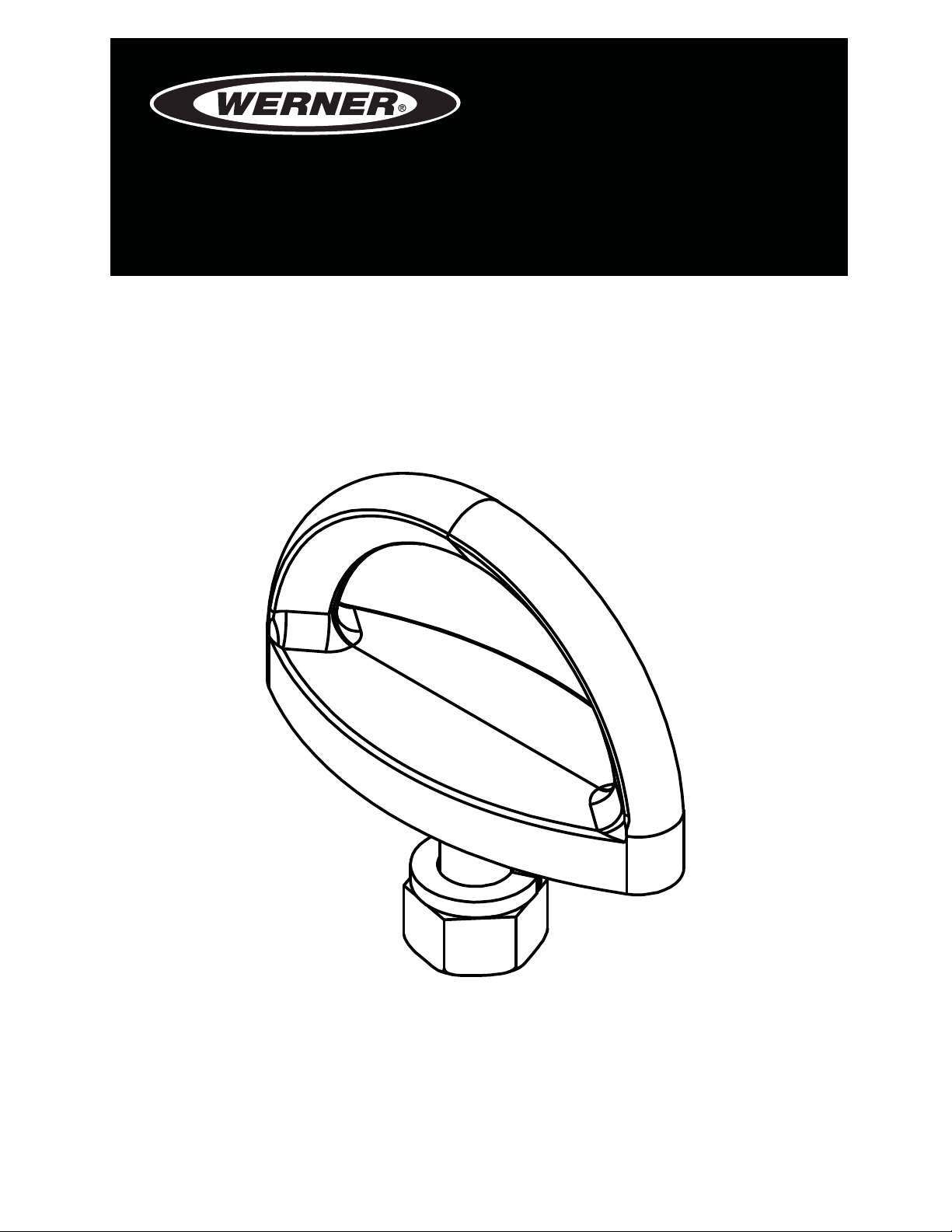
D-BOLT ANCHORS
Complies with ANSI Z359.1-2007; OSHA 29 CFR 1910 and 1926
regulations.
ANCLAJES TIPO D-Bolt
Cumple con las normas ANSI Z359.1-2007; OSHA 29 CFR 1910 y 1926.
(This manual applies to D-Bolt anchors with model numbers starting A320)
(Este manual aplica a todos los anclajes tipo D-Bolt con números de
modelo que comienzan con A320
Werner Fall Protection 724-588-2000
93 Werner Rd. 888-523-3371 toll free/ llamada gratuita
Greenville, PA 16125 888-456-8458 fax
.)
Page 2

CAUTION!
If use of fall protection equipment is necessary then the work
environment is dangerous and potentially deadly. Werner Company
products are designed to eliminate as much of the hazard as possible
but can do that ONLY if they are used correctly. Use this equipment as
it was designed to be used, after appropriate training, under the direct
supervision of a competent person, according to the instructions
provided, and in accordance with OSHA and local safety regulations.
User MUST read and understand all cautions and instructions. Failure
to heed these guidelines could result in injury or even death. Please,
WORK SAFE! WORK SMART!
ENGLISH
Page 2
Page 3

D-BOLT ANCHORS
USER INSTRUCTIONS
Contents
I. BEFORE USING THE D-BOLT ANCHOR .......................................................... 4
a. Inspect ......................................................................................................................4
b. Compatibility ............................................................................................................5
c. Fall Protection Plan ..................................................................................................5
d. Training .....................................................................................................................8
II. D-BOLT ANCHOR INSTALLATION AND USE .................................................8
a. Making a Connection ...............................................................................................8
b. Anchorage Strength .............................................................................................. 10
c. Connector ...............................................................................................................10
d. Body Support ......................................................................................................... 11
e. Mounting Locations ...............................................................................................11
f. Installation ...............................................................................................................12
III. USE WARNINGS, RESTRICTIONS AND CAUTIONS ................................... 13
a. Purpose ..................................................................................................................13
b. Rated Capacity .......................................................................................................13
c. Dimensions.............................................................................................................13
d. Limitations..............................................................................................................14
e. Requirements .........................................................................................................14
IV. LABELS/IDENTIFICATION/INSPECTION RECORDS .................................. 15
V. EQUIPMENT RECORDS ................................................................................16
VI. INSPECTION RECORDS .............................................................................. 16
Page 3
ENGLISH
Page 4
WARNING!
This product is just one part of a personal fall arrest system. It must
be matched correctly with other components to form a complete and
functional system. The user must understand the function of each of
these components and follow the manufacturer’s instructions for use
for each. The user must be provided these instructions, should read
and follow them, and consult the competent person who will supervise
his work if he has any questions about any part of the instructions.
The employer must provide training in the proper use, inspection, and
maintenance of all components in the system, and these instructions
can be used as part of that training. The equipment should be used
ONLY in accordance with these instructions, local ordinances and
codes, the applicable OSHA and ANSI standards, and the employer’s
safety plan. Alterations or misuse of this product or failure to follow
instructions may result in serious injury or death.
IF YOU HAVE ANY QUESTIONS ABOUT ANYTHING IN THESE
INSTRUCTIONS, THE EQUIPMENT, OR PROPER USE OF THE
EQUIPMENT, CONTACT WERNER CO. FOR MORE INFORMATION.
I. Before Using the D-Bolt Anchor
Before using this equipment the user should take certain steps to
ensure that it is in suitable condition and safe for use. Users must
read and understand these instructions. It is the employer’s obligation
to ensure that all users have been trained in safe work procedures
as well as in the use and limitations of fall protection equipment. All
users should be aware of and comply with all applicable OSHA, ANSI
and local or regional regulations concerning fall protection equipment
and its use.
a. Inspect
Examine all equipment thoroughly, daily before use by the user,
and periodically by a competent person who is not the user.
1. Ensure that the D-Bolt Anchor is free from rust, corrosion and any
damage. Clean with warm soapy solution to prevent damaging
the D-Bolt Anchor or structure.
ENGLISH
2. Ensure that the nut is securely tightened and the Lock Washer
remains engaged. If the nut and lock washer become loose, re-
Page 4
Page 5

D-BOLT ANCHORS
USER INSTRUCTIONS
tighten the nut to the torque speci ed in section II.f.
3. Inspect the D-Bolt Anchor to ensure there are no cracks, dents
or marks on the anchorage.
4. Make sure labels are attached to the D-Bolt Anchor and are
legible.
5. Record the inspection date and results in the Inspection and
Maintenance Log.
6. If inspection reveals a defective condition or abnormalities in
any of these areas, remove unit from service immediately. A
competent person should be consulted to determine if that item
is safe for continued use or if it should be destroyed.
IMPORTANT: If this equipment has been subjected to forces
resulting from the arrest of a fall, it must be immediately removed
from service.
b. Compatibility
Werner Co. equipment is designed for use with Werner Co. approved
components and subsystems only. Substitutions or replacements
made with non-approved components or subsystems may
jeopardize compatibility of equipment and may affect the safety and
reliability of the complete system.
Connectors are considered to be compatible with connecting
elements when they have been designed to work together in such a
way that their sizes and shapes do not cause their gate mechanisms
to inadvertently open regardless of how they become oriented.
Contact Werner Co. if you have any questions about compatibility.
Connectors (hooks, carabiners, and D-rings) must be capable of
supporting at least 5,000 pounds (22.2kN). Connectors must be
compatible with the anchorage or other system components. Do not
use equipment that is not compatible. Non-compatible connectors
may unintentionally disengage. Connectors must be compatible in
size, shape, and strength. Self locking snap hooks and carabiners
are required by ANSI Z359 and OSHA.
c. Fall Protection Plan
Plan your fall arrest or restraint system before starting your work.
Take into consideration all factors affecting your safety at any
time during use. The following list gives some important points to
consider when planning your system:
Page 5
ENGLISH
Page 6
1. ANCHORAGE: Select a rigid anchorage point that is capable of
supporting the required loads. See section II.b.
The anchorage location must be carefully selected to reduce
possible free fall and swing fall hazards and to avoid striking an
object during a fall. For restraint systems the anchorage must be
located such that no vertical free fall is possible. For fall arrest
systems OSHA requires the anchorage be independent of the
means suspending or supporting the user.
2. FREE FALL: Do not work above the anchorage level; increased
fall distance will result. Personal fall arrest systems must be
rigged such that the potential free fall is never greater than 6
feet (1.83 m). Restraint systems must be rigged such that there
is no possible vertical free fall.
3. FALL ARREST FORCES: The assembled fall arrest system
must keep fall arrest forces below 1,800 pounds (8 kN) when
used with a full body harness. Do not use a body belt for fall
arrest.
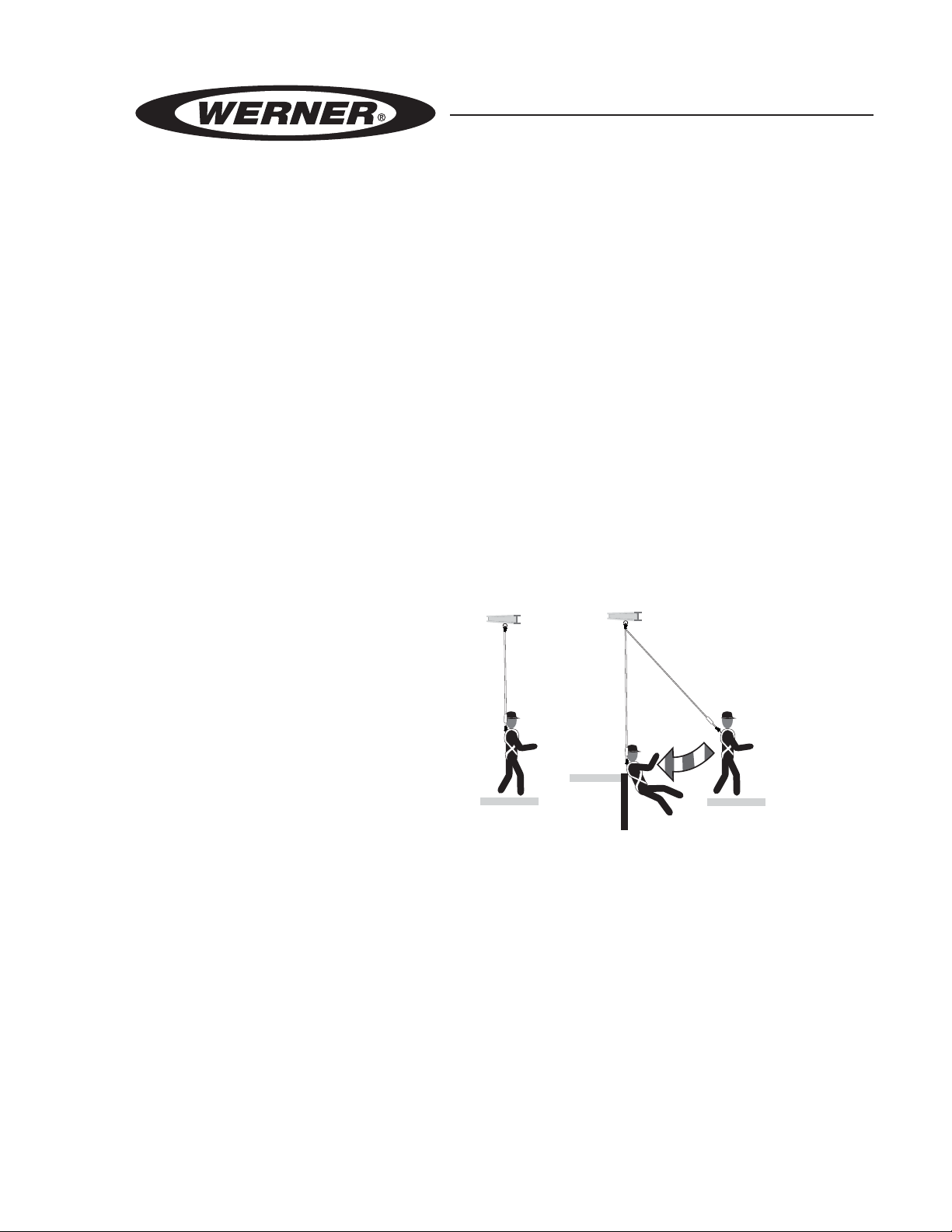
SWING FALL
4. SWING FALLS: Swing
falls occur when the
Anchorages
HAZARD
anchorage point is not
directly above the point
where a fall occurs. The
force of striking an object
in a swing fall may cause
serious injury or death.
Minimize swing falls by
working as close to the
Correct Incorrect
anchorage point as possible. Do not permit a swing fall if injury
could occur. Swing falls will signi cantly increase the clearance
required when a self-retracting lifeline or other variable length
connecting subsystem is used.
ENGLISH
Page 6
5. FALL CLEARANCE: Make certain enough clearance exists
in your fall path to prevent striking an object. The amount of
clearance needed is dependent upon the type of connecting
subsystem used and anchorage location. See connecting
subsystem user instructions for more information.
6. RESCUE: Should a fall occur, the user (employer) must have a
rescue plan. If a worker falls and is forced to remain suspended
for any length of time, physical damage to the body or even
death can result. For this reason Werner, OSHA, ANSI and
Page 7
D-BOLT ANCHORS
USER INSTRUCTIONS
most local regulations require that a rescue plan and the means
to implement the rescue plan are in place before use of this
equipment.
7. AFTER A FALL: Any equipment which has been subjected
to the force of arresting a fall must be removed from service
immediately.
WARNING!
Never connect more than one personal fall arrest or restraint system
to this device.
WARNING!
Follow manufacturer’s instructions for associated equipment used in
your fall protection or restraint system.
d. Training
OSHA, ANSI, and most local ordinances require that workers using
this product receive adequate training before use of this product.
These instructions and their entire contents should be a part of that
training.
II. D-Bolt Anchor Installation and Use
WARNING!
Do not alter or intentionally misuse this equipment. Consult with
Werner Co. if using this equipment with components or subsystems
other than those described in this manual. Some subsystem and
component combinations may interfere with the operation of this
equipment. Use caution when using this equipment around moving
machinery, electrical hazards, chemical hazards, and sharp edges.
WARNING!
Do not use this device if you are unable to tolerate the impact of
a fall arrest. Age and tness can seriously affect your ability to
withstand a fall. Pregnant women and minors must not use this
equipment.
a. Making Connections
1. Only use self-locking snap hooks and carabiners with this
equipment. Only use connectors that are suitable to each
Page 7
ENGLISH
Page 8
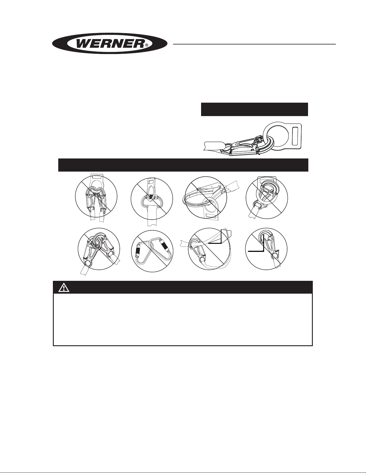
application. Ensure all connections are compatible in size, shape
and strength. Do not use equipment that is not compatible.
Ensure all connectors are fully closed and locked.
2. Werner Co. connectors (snap
hooks and carabiners) are
designed to be used only as
speci ed in each product’s
user’s instructions. See
inappropriate connections.
INAPPROPRIATE CONNECTIONS
NO! NO! NO! NO!
PROPER CONNECTION
NO!NO!NO!NO!
WARNING!
Large throat opening snap hooks should not be connected to
standard size D-rings or similar objects which will result in a load
on the gate if the hook or D-ring twists or rotates. Large throat snap
hooks are designed for use on xed structural elements such as
rebar or cross members that are not shaped in a way that can capture
the gate of the hook.
Werner Co. snap hooks and carabiners should NOT be
connected:
i. to a D-ring to which another connector is attached.
ii. in a manner that would result in a load on the gate. If the
connecting element that a snap hook or carabiner attaches
to is undersized or irregular in shape, a situation could occur
where the connecting element applies a force to the gate of
the snap hook or carabiner. This force may cause the gate
ENGLISH
(of either a self-locking or a non-locking snap hook) to open,
allowing the snap hook or carabiner to disengage from the
Page 8
connecting point.
Page 9

D-BOLT ANCHORS
USER INSTRUCTIONS
iii. in a false engagement, where features that protrude from
the snap hook or carabiner catch on the anchor and without
visual con rmation seems to be fully engaged to the anchor
point.
iv. to each other.
v. directly to webbing or rope lanyard or tie-back (unless
the manufacturer’s instructions for both the lanyard and
connector speci cally allow such a connection).
vi. to any object which is shaped or dimensioned such that the
snap hook or carabiner will not close and lock, or that rollout could occur.
3. When using an energy-absorbing lanyard, connect the energy
absorber “pack” end to the harness.
b. Anchorage Strength
Depending on the application, the anchorage to which the D-Bolt
Anchor is installed must meet strengths as given below:
1. FALL ARREST: Anchorages selected for personal fall arrest
systems (PFAS) shall have a strength capable of sustaining
static loads, applied in the directions permitted by the PFAS, of
at least; (A) 3,600 pounds (16kN) when certi cation exists (see
ANSI Z359.1 for certi cation de nition), or (B) 5,000 pounds
(22kN) in the absence of certi cation. When more than one
PFAS is attached to an anchorage, the anchorage strengths
set forth in (A) and (B) above shall be multiplied by the number
of personal fall arrest systems attached to the anchorage. Per
OSHA 29 CFR 1926.500 and 1910.66; Anchorages used for
attachment of PFAS shall be independent of any anchorage
being used to support or suspend platforms, and capable of
supporting at least 5,000 pounds (22kN) per user attached, or be
designed, installed, and used as part of a complete PFAS which
maintains a safety factory of at least two, and is supervised by
a quali ed person.
2. RESTRAINT: Anchors selected for restraint applications must be
attached to a roof member capable of sustaining a static load of
at least 3,000 pounds (13 kN) applied in any direction permitted
by the restraint system when in use. Each roof member anchor
installation must be independently capable of sustaining this
load.
Page 9
ENGLISH
Page 10
WARNING!
Restraint anchorages may only be used where there is no possible
vertical free fall. Restraint anchorages do not have sufficient strength
for fall arrest. Do not connect personal fall arrest systems to restraint
anchorages.
c. Connector
For fall arrest systems Werner Co. recommends using energy
absorbing lanyards incorporating self locking snap hooks or selfretracting lifelines. Lanyards labeled ANSI A10.14 Type II must
not be used for fall arrest applications. All lanyards must have a
minimum breaking strength of 5,000 pounds (22kN).
NOTE: Applications such as working near high voltage may require
special lifeline materials, consult Werner Co. before using such
lifelines.
d. Body Support
The recommended body support for fall arrest applications is a full
body harness. For restraint applications a body belt may be used.
e. Mounting location
The D-Bolt Anchor should be positioned on the mounting surface
ENGLISH
so that the attached connector will never be subjected to dynamic
loading on the keeper system . Werner D-Bolt Anchors may
be installed on overhead horizontal or vertical surfaces. Other
installation applications must be approved by Werner Co.
1. The entire base of the D-Bolt Anchor must be ush with the
mounting surface.
2. The area of the mounting surface for the D-Bolt Anchor must
be such that no dynamic forces get applied to the attached
connector’s keeper system.
Page 10
Page 11

D-BOLT ANCHORS
USER INSTRUCTIONS
Minimum load
bearing surface to
extend entire length
of anchorage and
snap hook.
Minimum load
bearing surface
DOES NOT extend
entire length of
anchorage and snap
hook.
Minimum load
bearing surface
DOES NOT extend
entire length of
anchorage hook.
f. Installation
Install the D-Bolt Anchor at the correct mounting locations in the
following manner:
1. D-Bolt A320001 and A320001-WB:
i. Pre-drill a 21/32 inch (16.7 mm) hole into the desired structure,
using a suitable drill bit for penetration. Remove any burred
edges from the structure to ensure that the xed anchorage
point sits ush against the mounting surface. The location of
the drilled hole must be suitable to take the forces de ned
in Section II.b.
ii. Use only Werner approved bolts and fasteners with this
anchor. User must supply an approved 5/8 inch (16 mm)
grade 8 bolt for use with D-Bolt A320001. Fasteners are
included with D-Bolt A320001-WB.
iii. Insert the bolt through the D-Bolt and the pre-drilled hole.
Ensure that the bolt is pushed through completely, and the
back surface of the D-ring is ush against the structure.
iv. Slide a lock washer over the threads of the bolt until the
washer is ush against the surface of the structure.
v. Thread the nut onto the bolt until it meets the washer. Ensure
the D-ring is oriented correctly and then torque the nut
Page 11
ENGLISH
Page 12

tight. Recommended torque is 125 ft-lbs (169.5 N-m). Once
tightened, at least one full thread must extend beyond the
nut. Do not overtighten.
vi. Inspect the D-Bolt Anchor to ensure that it is not loose and
sits ush against the structure.
2. D-Bolt A320002:
i. Pre-drill a 17/32 inch (13.5 mm) hole into the desired structure,
using a suitable drill bit for penetration. Remove any burred
edges from the structure to ensure that the xed anchorage
point sits ush against the mounting surface. The location of
the drilled hole must be suitable to take the forces de ned
in Section II.b.
ii. Insert the D-Bolt through the pre-drilled hole. Ensure that the
bolt is pushed through completely, and the back surface of
the D-ring is ush against the structure.
iii. Slide the lock washer over the threads of the D-Bolt until the
washer is ush against the surface of the structure.
iv. Thread the nut onto the D-Bolt until it meets the washer.
Ensure the D-ring is oriented correctly and then torque the
nut tight. Recommended torque range is 45-55 ft-lbs (61
- 74.5 N-m). Once tightened, at least one full thread must
extend beyond the nut. Do not overtighten.
v. Inspect the D-Bolt Anchor to ensure that it is not loose and
sits ush against the structure.
III. Use Warnings, Restrictions and Cautions
a. Purpose
Werner Co. D-Bolt Anchors provide a permanent or semipermanent
anchorage point for personal fall arrest systems where anchorage
on a surface is required. The D-Bolt Anchor’s vertical anchor area
will accommodate all of Werner Co. snap hooks and carabiners.
b. Rated Capacity
Refer to connecting device or subsystem instructions for limitations
of worker weight and number of workers.
NOTE: No more than one connection may be attached to this device.
ENGLISH
Page 12
See c. Limitations.
Page 13

D-BOLT ANCHORS
USER INSTRUCTIONS
c. Limitations
The following application limitations must be recognized and
considered before using this product:
1. FREE FALL: Restraint systems must be rigged such that there is
no possible vertical free fall. Personal fall arrest systems must be
rigged in such a way to limit the free fall to 6 feet (1.83 m) (ANSI
Z359.1). See associated connecting subsystem manufacturer’s
instructions for further information.
2. FALL CLEARANCE: Make certain that enough clearance exists
in your fall path to prevent striking an object. The amount of
clearance required is dependent upon the type of connecting
subsystem used (lanyard, lifeline), the anchorage location, and
the amount of stretch in the lifeline. See section I.c for more
information on determining fall clearance.
3. ENVIRONMENTAL HAZARDS: Use of this equipment in areas
with environmental hazards may require additional precautions
to prevent injury to the user or damage to the equipment.
Hazards may include, but are not limited to: heat, chemicals,
corrosive environments, high voltage power lines, gases, moving
machinery, and sharp edges.
4. TRAINING: This equipment is to be used by persons who have
been properly trained in its correct application and use.
d. Requirements
Refer to applicable local, state, and federal (OSHA) regulations
governing this equipment for more information on anchorages
and associated system components, including; ANSI Z359.1, and
OSHA 29 CFR 1910.66, appendix C.
Page 13
ENGLISH
Page 14

IV. Labels/Identi cation/Inspection Records
a. All products should be inspected by the user thoroughly before
each use. Additional inspections by a competent person other than
the user should be conducted at least annually. That interval should
be shortened any time the product is used in a harsh environment
or is exposed to conditions such as chemicals, abrasion, heat or
any other factor that could affect the strength of any of the materials
or components.
b. This manual should always accompany the product, or be on le
with the employer for access when needed. Record the identi cation
details for the anchor and record the inspections in the inspection
log. It is important to keep this log current, complete, and available
as needed.
ID / Warning Label
ENGLISH
WARNING
Read User Manual and understand
all instructions and warnings. Refer
to the instruction manual for stability
and compatibility limitations. If user
manual is missing contact Werner
Co. for a replacement copy. The blue
wear sleeve must protrude past the
edge of the concrete after installation.
Product must be inspected prior to
each use according to instructions in
manual, then periodically by a
competent person who is not the user.
User repairs or alterations are NOT
permitted. Avoid exposure to sharp
edges, chemicals, machinery and
environmental hazards that could
weaken the materials. Verify that
connectors are compatible (see
instruction manual). OSHA, CSA and
local regulations require that workers
receive training in the proper use and
limitations of fall restraint equipment.
FAILURE TO READ AND HEED ALL
WARNINGS COULD RESULT IN INJURY
OR DEATH!
93 Werner Road, Greenville, PA 16125
888-523-3370 • www.wernerladder.com
Page 14
Page 15

D-BOLT ANCHORS
USER INSTRUCTIONS
Standards/Estándares
ANSI Z359.1-2007, OSHA 1910-1926
Model/Modelo:
Material
Materiales:
Maximum Capacity:
Capacidad máxima:
Year of Manufacture:
Año de la fabricación:
Greenville, PA 16125 • 888-523-3371
310 lb./141 kg
2016
Minimum Breaking Strength:
Resistencia a Ruptura Mínima:
5,000lbs / 22.2 kN
Model / Modelo:
A320001-WB
Materials:
Materiales:
Steel / Acero
Date of
Manufacture:
Fecha de
la Fabricación:
Serial Number:
Número de Serie:
XX/XX
xxxxxx
Max Capacity
(user with tools):
Capacidad Máxima
(usuario con las
herramientas):
Assembled in:
Ensemblado en:
400 lb
181 kg
US
Inspection Log/Registro de Inspección
Yea r
Yea r
Yea r
Yea r
Año
1
2
Año
3
Año
Año
Yea r
4
5
Año
1
2
3
4
5
6
7
8
9
10
11
12
Standards/Estándares
ANSI Z359.1-2007, OSHA 29 CFR 1910, 1926
93 Werner Road, Greenville, PA 16125
1-888-523-3371 • www.wernerco.com
© 2016 Werner Co.
P/N 110643-01 Rev A 8/16
Warning: User must follow manufacturer’s instructions
included with the equipment at the time of shipment
from the manufacturer. Refer to the instruction manual
for proper installation and stability and compatibility
limitations. Inspect prior to use.
Page 15
ENGLISH
Page 16

V. Equipment Record
PART NUMBER
SERIAL NUMBER
DATE
MANUFACTURED
PURCHASE DATE
ASSIGNED TO
SPECIFICATIONS
Werner D-Bolt Anchor
Certi ed to meet the ANSI Z359.1-2007 standard and OSHA 29 CFR
1910 and 1926 regulations for the subsystem components of a complete
personal fall arrest system.
Individually bar coded model and serial numbers, location and date of
manufacture are on product label.
VI. Inspection Record
ENGLISH
Page 16
INSPECTION RECORD
DATE INSPECTOR PASS/FAILDATE INSPECTOR PASS/FAIL
Page 17

ANCLAJES TIPO D-BOLT
INSTRUCCIONES PARA EL USUARIO
Advertencia:
Si el uso de equipos de protección contra caídas es necesario,
entonces el ambiente de trabajo es peligroso y potencialmente
mortal. Los productos Werner Company están diseñados para
eliminar peligros tanto como sea posible, pero SÓLO si estos
productos se utilizan correctamente. Utilice este equipo tal como
fue diseñado para usarse, después de una capacitación apropiada,
bajo la supervisión directa de una persona cali cada, de acuerdo con
las instrucciones suministradas, y de acuerdo con las regulaciones
OSHA y las regulaciones de seguridad locales. El usuario DEBE leer y
entender todas las precauciones e instrucciones. No tener en cuenta
estas directrices podría resultar en lesiones o incluso la muerte.
Por favor, ¡TRABAJE DE MANERA SEGURA! ¡TRABAJE DE MANERA
INTELIGENTE!
Página 17
ESPAÑOL
Page 18

Contenido
I. INSTRUCCIONES PARA EL USUARIO ..........................................................17
a. Inspeccione ............................................................................................................19
b. Compatibilidad .......................................................................................................20
c. Plan de protección contra caídas .........................................................................20
d. Capacitación ..........................................................................................................23
II. INSTALACIÓN Y USO DEL ANCLAJE TIPO D-BOLT .................................... 23
a. Realización de una conexión ................................................................................23
b. Resistencia del anclaje..........................................................................................25
c. Conector .................................................................................................................25
d. Soporte del cuerpo ................................................................................................26
e. Ubicaciones de montaje ........................................................................................26
f. Instalación ..............................................................................................................27
III. TENGA EN CUENTA LAS ADVERTENCIAS,
RESTRICCIONES Y PRECAUCIONES .........................................................28
a. Propósito ..............................................................................................................28
b. Capacidad nominal ................................................................................................28
c. Dimensiones...........................................................................................................28
d. Limitaciones ...........................................................................................................29
c. Requisitos ..............................................................................................................29
IV. ETIQUETAS/IDENTIFICACIÓN/REGISTROS DE INSPECCIÓN .................. 29
V. REGISTROS DE EQUIPOS ............................................................................31
VI. REGISTROS DE INSPECCIÓN ..................................................................... 31
ESPAÑOL
Página 18
Page 19

ANCLAJES TIPO D-BOLT
INSTRUCCIONES PARA EL USUARIO
Advertencia:
Este producto es sólo una parte de un sistema personal de detención de
caídas. Éste debe combinarse correctamente con otros componentes para
conformar un sistema completo y funcional. El usuario debe entender la
función de cada uno de estos componentes y seguir las instrucciones del
fabricante para el uso de cada componente. El usuario debe recibir estas
instrucciones, debe leerlas y seguirlas, y consultar a la persona cali cada que
supervisará su trabajo si tiene alguna pregunta acerca de cualquier parte de
las instrucciones. El empleador debe proporcionar capacitación sobre el uso
apropiado, inspección y mantenimiento de todos los componentes del sistema,
y estas instrucciones pueden utilizarse como parte de esa capacitación. El
equipo SÓLO debe utilizarse de acuerdo con estas instrucciones, ordenanzas
y códigos locales, las normas OSHA y ANSI aplicables, y el plan de seguridad
del empleador. Las alteraciones o uso incorrecto de este producto, o no
seguir estas instrucciones, podría resultar en lesiones graves o la muerte.
SI USTED TIENE ALGUNA PREGUNTA ACERCA DE ALGO DE ESTAS
INSTRUCCIONES, EL EQUIPO O EL USO APROPIADO DEL EQUIPO,
COMUNÍQUESE CON WERNER CO. PARA OBTENER MÁS INFORMACIÓN.
I. Antes de utilizar el anclaje tipo D-Bolt
Antes de utilizar este equipo, el usuario debe realizar ciertos pasos para
garantizar que éste está en condiciones apropiadas y es seguro para su uso.
Los usuarios deben leer y entender estas instrucciones. Es obligación del
empleador garantizar que todos los usuarios hayan recibido capacitación
sobre los procedimientos de trabajo seguros y también sobre el uso y
limitaciones de los equipos de protección contra caídas. Todos los usuarios
deben estar informados acerca de y cumplir todas las normas OSHA, ANSI
aplicables y las normas locales o regionales relacionadas con los equipos
de protección contra caídas y su uso.
a. Inspeccione
Todo el equipo debe ser examinado completamente, diariamente antes
del uso, por parte del usuario; y periódicamente por parte de una persona
cali cada que no sea el usuario.
1. Veri que que el anclaje tipo D-Bolt no tiene óxido, corrosión ni ningún
daño. Limpie con una solución jabonosa tibia para evitar dañar el
anclaje tipo D-Bolt o la estructura.
2. Veri que que la tuerca está apretada rmemente y que la arandela
de seguridad permanece enganchada. Si la tuerca y la arandela de
seguridad están ojas, re-apriete la tuerca.
Página 19
ESPAÑOL
Page 20

3. Inspeccione el anclaje tipo D-Bolt para garantizar que no hay grietas,
abolladuras o marcas en el anclaje.
4. Veri que que las etiquetas están sujetadas al anclaje tipo D-Bolt y que
están legibles.
5. Registre la fecha y resultados de la inspección en el registro de
inspección y mantenimiento.
6. Si la inspección revela una condición defectuosa o anormalidades en
cualquiera de estas áreas, retire inmediatamente del servicio la unidad.
Debe consultarse a una persona capacitada para determinar si ese
elemento es seguro para uso continuado o si debe destruirse.
IMPORTANTE: Si este equipo ha sido sometido a las fuerzas resultantes
de una detención de caída, éste debe retirarse inmediatamente del
servicio.
b. Compatibilidad
Los equipos Werner Co. están diseñados para uso sólo con componentes
y subsistemas aprobados por Werner Co. Las sustituciones o reemplazos
realizados con componentes o subsistemas no aprobados podrían
arriesgar la compatibilidad del equipo y podrían afectar la seguridad y
con abilidad del sistema completo.
ESPAÑOL
Los conectores se consideran compatibles con los elementos conectivos
cuando éstos han sido diseñados para trabajar en conjunto de tal manera
que sus tamaños y formas no causen que sus mecanismos de cierre
se abran inadvertidamente sin importar la manera como se orienten.
Comuníquese con Werner Co. si usted tiene alguna pregunta acerca
de la compatibilidad. Los conectores (ganchos, argollas rectangulares
metálicas y los anillos en ‘D’) deben ser capaces de soportar 22,2kN
(5000 lbs). Los conectores deben ser compatibles con el ancladero u otros
componentes del sistema. No utilice equipos que no sean compatibles.
Los conectores no compatibles podrían desengancharse accidentalmente.
Vea las conexiones inapropiadas. Los conectores deben ser compatibles
en tamaño, forma y resistencia. Las normas ANSI Z359 y OSHA
requieren argollas rectangulares metálicas y ganchos de cierre resortado
autoasegurables.
c. Plan de protección contra caídas
Planee su sistema de detención o evitamiento de caídas antes de iniciar
su trabajo. Tenga en cuenta todos los factores que afectan su seguridad en
cualquier momento durante el uso. La siguiente lista proporciona algunos
puntos importantes que deben considerarse al planear su sistema:
Página 20
Page 21

ANCLAJES TIPO D-BOLT
INSTRUCCIONES PARA EL USUARIO
1. ANCLADERO: Seleccione un punto de anclaje rígido que sea capaz
de soportar las cargas requeridas. Vea la sección II.b. La ubicación del
anclaje debe seleccionarse cuidadosamente para reducir la posibilidad
de peligros por caída libre o por caída tipo columpio y para evitar
golpear un objeto durante una caída. Para los sistemas de evitamiento
de caídas, el anclaje debe ubicarse de modo que no sea posible
una caída libre vertical. Para los sistemas de detención de caídas,
OSHA exige que el anclaje sea independiente de los elementos que
suspenden o soportan el usuario.
2. CAÍDA LIBRE: No trabaje encima del nivel del anclaje porque existirá
una mayor distancia de caída. Los sistemas personales de detención de
caídas deben instalarse de modo que la posible caída libre nunca sea
superior a 1,83 m (6 pies). Deben instalarse sistemas de evitamiento
de caídas de modo que no haya posibilidad de caídas libres verticales.
3. FUERZAS DE DETENCIÓN DE CAÍDAS: El sistema de detención de
caídas ensamblado debe mantener las fuerzas de detención de caídas
por debajo de 8 kN (1800 lbs) cuando se utiliza con un arnés de cuerpo
completo. No utilice un cinturón de cuerpo para las aplicaciones de
detención de caídas.
4. CAÍDAS TIPO COLUMPIO:
Peligro de caída
tipo columpio
Las caídas tipo columpio
ocurren cuando el punto de
Anclajes
anclaje no está directamente
encima del punto donde
ocurre una caída. La fuerza
al golpear un objeto en una
caída tipo columpio podría
causar lesiones graves o la
muerte. Minimice las caídas
Correcto Incorrecto
tipo columpio trabajando lo
más cerca posible del punto de anclaje. No permita una caída tipo
columpio si hay posibilidad de ocurrencia de lesiones. Las caídas tipo
columpio aumentarán signi cativamente el espacio libre requerido
cuando se utiliza una cuerda salvavidas autoretráctil u otro subsistema
de conexión de longitud variable.
5. ESPACIO LIBRE DE CAÍDA: Veri que que existe su ciente espacio
libre en la trayectoria de caída para evitar golpear un objeto. La cantidad
de espacio libre necesario depende del tipo de subsistema conectivo
utilizado y de la ubicación del anclaje. Vea las tablas de distancia
de caída para las cuerdas absorbedoras de impacto o la distancia
de caída para las cuerdas salvavidas autoretráctiles para calcular el
espacio libre de caída.
Página 21
ESPAÑOL
Page 22

6. RESCATE: Si ocurre una caída, el usuario (empleador) debe
tener un plan de rescate. Si un trabajador cae y queda obligado a
permanecer suspendido durante cualquier período de tiempo, podría
producirse daño físico o incluso la muerte. Por este motivo; Werner, las
regulaciones de OSHA, ANSI y la mayoría de las regulaciones locales
exigen la existencia de un plan de rescate y los medios para ejecutar
un plan de rescate, antes del uso de este equipo.
7. DESPUÉS DE UNA CAÍDA: Cualquier equipo que ha sido sometido a
una fuerza de detención de caída debe retirarse inmediatamente del
servicio.
Advertencia:
Nunca conecte más de un sistema personal de detención o evitamiento
decaídas a un solo anclaje tipo D-Bolt.
Advertencia:
Siga las instrucciones del fabricante para el equipo respectivo utilizado en su
sistema de protección contra caídas o de evitamiento de caídas.
d. Capacitación
Las regulaciones OSHA, ANSI, y la mayoría de las regulaciones locales
exigen que los trabajadores que utilicen este producto deben recibir
capacitación adecuada antes del uso de este producto. Estas instrucciones
y su contenido completo deben ser parte de esa capacitación.
II. Instalación y uso del anclaje tipo D-Bolt
Advertencia:
No altere ni utilice incorrectamente intencionalmente este equipo. Consulte
con Werner Co. si este equipo se utilizará con componentes o subsistemas
diferentes a los descritos en este manual. Algunos subsistemas y
combinaciones de componentes podrían interferir con la operación de este
equipo. Tenga precaución al utilizar este equipo alrededor de máquinas en
movimiento, peligros eléctricos, peligros químicos y bordes losos.
Advertencia:
No utilice este dispositivo si usted no puede tolerar el impacto de una
detención de caída. La edad y la condición física pueden afectar seriamente
su capacidad para soportar una caída. Las mujeres embarazadas y los
menores de edad no deben utilizar este equipo.
a. Realización de las conexiones
ESPAÑOL
Página 22
1. Con este equipo, sólo utilice argollas rectangulares metálicas y ganchos
de cierre resortado auto-asegurables. Sólo utilice conectores que sean
Page 23

ANCLAJES TIPO D-BOLT
INSTRUCCIONES PARA EL USUARIO
apropiados para cada aplicación. Veri que que todas las conexiones
son compatibles en tamaño, forma y resistencia. No utilice equipos que
no sean compatibles. Veri que que todos conectores están totalmente
cerrados y asegurados.
2. Los conectores Werner Co.
(ganchos de cierre resortado y
argollas rectangulares metálicas)
están diseñados para utilizarse
únicamente según se especi ca
en las instrucciones para
usuario de cada producto. Vea
las conexiones inapropiadas.
CONEXIONES INAPROPIADAS
NO! NO! NO! NO!
CONEXIONES APROPIADAS
NO!NO!NO!NO!
Advertencia:
Los ganchos de cierre resortado que se abren hasta una garganta grande no
deben conectarse a anillos en ‘D’ de tamaño estándar u objetos similares, lo
cual resultará en una carga sobre el cierre si el gancho o anillo en ‘D’ gira o
rota. Los ganchos de cierre resortado de garganta grande están diseñados
para uso en elementos estructurales jos tales como barras de refuerzo o
travesaños que no tengan una forma que pueda atrapar el cierre del gancho.
Los ganchos de cierre resortado y las argollas rectangulares metálicas de
Werner Co. NO deben conectarse:
i. a un anillo en ‘D’ al cual está sujetado otro conector.
ii. de tal manera que se produzca carga sobre el cierre. Si el elemento
conectivo al cual se sujeta un gancho de cierre resortado o una
argolla rectangular metálica es de tamaño inferior o tiene forma
irregular, podría ocurrir un problema cuando el elemento conectivo
Página 23
ESPAÑOL
Page 24

aplique una fuerza al cierre del gancho de cierre resortado o la argolla
rectangular metálica. Esta fuerza podría causar que se abra el cierre
(de un gancho de cierre resortado auto-asegurable o no-asegurable),
permitiendo que el gancho de cierre resortado o la argolla rectangular
metálica se desenganche del punto de conexión.
iii. en un enganche falso, donde las características que sobresalen
del gancho de cierre resortado o la argolla rectangular metálica se
agarran al anclaje, y sin con rmación visual parece estar totalmente
enganchado al punto de anclaje.
iv. uno al otro.
v. directamente a una correa tejida o cuerda de bras trenzadas o
amarre sobre sí mismo (a menos que las instrucciones del fabricante
de la cuerda y el conector permitan especí camente dicha conexión).
vi. a cualquier objeto que tenga una forma o dimensiones tales que el
gancho de cierre resortado o la argolla rectangular metálica no se
cierren ni aseguren, y que pudiera ocurrir rodaje.
3. Al utilizar una cuerda absorbedora de energía, conecte el extremo, con
“paquete” absorbedor de energía, al arnés.
b. Resistencia del anclaje
ESPAÑOL
Dependiendo de la aplicación, el ancladero al cual se instala el anclaje tipo
D-Bolt debe cumplir las resistencias según se indican a continuación:
1. DETENCIÓN DE CAÍDAS: Los ancladeros seleccionados para los Sistemas
Personales de Detención de Caídas (SPDC) deberán tener una resistencia
capaz de sostener cargas estáticas, aplicadas en las direcciones permitidas
por el SPDC, de al menos; (A) 16kN (3600 lbs) cuando existe certi cación
(vea la norma ANSI Z359.1 para obtener la de nición de certi cación), ó
(B) 22 kN (5000 lbs) en ausencia de certi cación. Cuando se sujeta más
de un (1) SPDC a un ancladero, las resistencias del ancladero establecidas
en (A) y (B) anteriores deberán multiplicarse por el número de sistemas
personales de detención de caídas sujetados al ancladero. Según las
normas OSHA 1926.500 y 1910.66; los ancladeros utilizados para sujeción
de los SPDC deberán ser independientes de cualquier ancladero que
se esté utilizando para soportar o suspender plataformas, y capaces de
soportar al menos 22 kN (5000 lbs) por cada usuario sujetado, o diseñarse,
instalarse y utilizarse como parte de un sistema completo personal de
detención de caídas que mantenga un factor de seguridad de dos como
mínimo, y sea supervisado por una persona capacitada.
2. EVITAMIENTO DE CAÍDAS: Los anclajes tipo D-Bolt instalados para
aplicaciones de evitamiento de caídas deben sujetarse a un componente
de techo capaz de soportar como mínimo una carga estática de 13 kN
(3000 lbs) aplicada en cualquier dirección permitida por el sistema de
evitamiento de caídas cuando está en uso.
Página 24
Page 25

ANCLAJES TIPO D-BOLT
INSTRUCCIONES PARA EL USUARIO
Advertencia:
Los anclajes para evitamiento de caídas sólo pueden utilizarse donde no existe
la posibilidad de una caída libre vertical. Los anclajes para evitamiento de caídas
no tienen su ciente resistencia para detener una caída. No conecte sistemas
personales de detención de caídas a anclajes para evitamiento de caídas.
c. Conector
Para los sistemas de detención de caídas, Werner Co. recomienda
utilizar cuerdas absorbedoras de energía que tengan ganchos de cierre
resortados auto-asegurables. Las cuerdas con etiqueta ANSI A10.14 tipo
II no deben utilizarse para aplicaciones de detención de caídas. Todas las
cuerdas deben tener una resistencia mínima a la rotura de 22 kN (5000
lbs).
NOTA: Las aplicaciones tales como trabajar cerca de cables de alto
voltaje podrían requerir materiales especiales de cuerda salvavidas,
consulte a Werner Co. antes de utilizar dichas cuerdas salvavidas.
d. Soporte del cuerpo
El soporte de cuerpo recomendado para todas las aplicaciones de
detención de caídas es un arnés de cuerpo completo. Para las aplicaciones
de evitamiento de caídas, puede utilizarse un cinturón de cuerpo.
e. Ubicación de montaje
El anclaje tipo D-Bolt debe colocarse en una supericie de montaje
de modo que el conector sujetado nunca será sometido a cargas
dinámicas sobre el sistema de cierre. Los anclajes tipo D-Bolt de
Werner pueden instalarse en supericies elevadas horizontales o
verticales. Otras aplicaciones de instalación deben ser aprobadas
por Werner Co.
1. Toda la base del anclaje tipo D-Bolt debe estar al ras con la supericie
de montaje.
2. El área de la supericie de montaje para el anclaje tipo D-Bolt debe ser
tal que no se aplique ninguna fuerza dinámica al sistema de cierre del
conector sujetado.
Página 25
ESPAÑOL
Page 26

La super cie
minima de apoyo
de carga debe
extenderse a lo
largo de toda la
longitud del anclaje
y del gancho.
f. Instalación
Instale el anclaje tipo D-Bolt en las ubicaciones de montaje correctas, de
la siguiente manera:
1. D-Bolt A320001 y A320001-WB:
i. Pre-taladre un ori cio de 16.7 mm (21/32 pulgadas) en la estructura
deseada, utilizando una broca apropiada para penetración. Elimine
cualquier borde con rebaba de la estructura para garantizar que
el punto de anclaje jo se asienta al ras contra la supericie de
montaje. La ubicación del ori cio taladrado debe ser apropiada
para recibir las fuerzas deinidas en la Sección II.b.
La super cie minima
de apoyo de carga
NO se extende a
lo largo de toda la
longitud del anclaje y
del gancho.
La super cie
minima de apoyo
de carga NO se
extende a lo largo
de toda la longitud
del anclaje.
ESPAÑOL
Página 26
ii. Con este anclaje, sólo utilice pernos y sujetadores aprobados por
Werner. El usuario debe suministrar un perno de 16 mm (5/8
pulgadas) grado 8 aprobado para uso con el D-Bolt A320001.
Tornillos de jaciónestán incluidos con D-Bolt A320001-WB.
iii. Inserte el perno a través del anclaje tipo D-Bolt y del ori cio pre-
taladrado. Veri que que el perno está insertado completamente,
y que la supericie trasera del D-Bolt está al ras con respecto a la
estructura.
iv. Deslice sobre las roscas del perno hasta que la arandela esté al ras
con respecto a la supericie de la estructura.
v. Enrosque la tuerca sobre el perno hasta que ésta se encuentre con
Page 27

ANCLAJES TIPO D-BOLT
INSTRUCCIONES PARA EL USUARIO
la arandela. Veri que que el D-Bolt está orientado correctamente y
luego apriete la tuerca. El torque de apriete recomendado es 169.5
N-m(125 libras-pie). Una vez apretado, al menos una (1) rosca
completa debe extenderse más allá de la tuerca.
vi. Inspeccione el anclaje tipo D-Bolt para garantizar que no está lojo
y que está asentado al ras con respecto a la estructura.
2. D-Bolt A320002:
i. Pre-taladre un ori cio de 13.5 mm (17/32 pulgadas) en la estructura
deseada, utilizando una broca apropiada para penetración. Elimine
cualquier borde con rebaba de la estructura para garantizar que
el punto de anclaje jo se asienta al ras contra la supericie de
montaje. La ubicación del ori cio taladrado debe ser apropiada
para recibir las fuerzas deinidas en la Sección II.b.
ii. Inserte el D-Bolt a través del ori cio pre-taladrado. Veri que que el
perno está insertado completamente, y que la supericie trasera
del D-Bolt está al ras con respecto a la estructura.
iii. Deslice la arandela de seguridad sobre las roscas del D-Bolt
hasta que la arandela esté al ras con respecto a la supericie de la
estructura.
iv. Enrosque la tuerca sobre el D-Bolt hasta que ésta se encuentre
con la arandela. Veri que que el anillo en ‘D’ está orientado
correctamente y luego apriete la tuerca. El rango de apriete
recomendado es 61 a 74.5 N-m (45 a 55 libras-pie). Una vez
apretado, al menos una (1) rosca completa debe extenderse más
allá de la tuerca.
v. Inspeccione el anclaje tipo D-Bolt para garantizar que no está ojo y
que está asentado al ras con respecto a la estructura.
III. Tenga en cuenta las advertencias, restricciones y
precauciones
a. Propósito
Los anclajes tipo D-Bolt de Werner Co. proporcionan un punto de
anclaje permanente o semipermanente para los sistemas personales
de detención de caídas donde se requiere un anclaje sobre una
supericie. El área de anclaje vertical del anclaje tipo D-Bolt alojará todos
los ganchos de cierre resortado y argollas rectangulares metálicas de
Werner Co.
Página 27
ESPAÑOL
Page 28

b. Capacidad nominal
Re érase a las instrucciones de conexión dispositivos o subsistemas para
las limitaciones de peso del trabajador y número de trabajadores.
NOTA: No puede sujetarse más de una (1) persona a este dispositivo. Vea el
numeral c. Limitaciones.
c. Limitaciones
Las siguientes limitaciones de aplicación deben reconocerse y tenerse en
cuenta antes de utilizar este producto:
1. CAÍDA LIBRE: Deben instalarse sistemas de evitamiento de caídas de
modo que no haya posibilidad de caídas libres verticales. Los sistemas
personales de detención de caídas deben instalarse de tal manera
que limiten una caída libre a 1.83 m (6 pies) (ANSI Z359.1). Vea las
instrucciones del fabricante del subsistema conectivo asociado para
obtener información adicional.
2. ESPACIO LIBRE DE CAÍDA: Veri que que existe su ciente espacio
libre en la trayectoria de caída para evitar golpear un objeto. La cantidad
de espacio libre necesario depende del tipo de subsistema conectivo
utilizado y de la ubicación del anclaje. Vea las instrucciones para el
usuario del subsistema conectivo para mas información.
3. RIESGOS AMBIENTALES: El uso de este equipo en lugares con
peligros ambientales podría requerir precauciones adicionales para
evitar lesiones al usuario o daño al equipo. Los peligros podrían ser,
entre otros, los siguientes: calor, productos químicos, ambientes
corrosivos, cables de energía de alto voltaje, gases, maquinaria en
movimiento y bordes ilosos.
4. CAPACITACIÓN: Este equipo de ser utilizado por personas que han
sido capacitadas apropiadamente en cuanto a su aplicación y uso
correctos.
d. Requisitos
Consulte los requisitos (OSHA) locales, estatales y federales aplicables
que rigen este equipo para obtener más información sobre los anclajes
y los componentes de sistema asociados, incluyendo; ANSI Z359.1, y
OSHA 29 CFR1910.66, anexo C.
IV. Etiquetas/Identi cación/Registros de inspección
a. Todos los productos deben ser inspeccionados completamente por el
ESPAÑOL
Página 28
Page 29

ANCLAJES TIPO D-BOLT
INSTRUCCIONES PARA EL USUARIO
usuario antes de cada uso. Una persona capacitada diferente al usuario
debe realizar inspecciones adicionales, al menos anualmente. Ese intervalo
debe acortarse cada vez que el producto se utiliza en un ambiente agresivo
o se expone a condiciones tales como productos químicos, abrasión, calor
o cualquier otro factor que pudiera afectar la resistencia de cualquiera de
los materiales o componentes.
b. Este manual siempre debe acompañar el producto o estar en los archivos
del empleador para consultarlo cuando se requiera. Registre los detalles
de identi cación para el anclaje y registre las inspecciones en el registro de
inspección mostrado. Es importante mantener este registro actualizado,
completo y disponible según se requiera.
Etiqueta de identiicación/ advertencia
ADVERTENCIA
Debe leer el manual del usuario y
entender todas las instrucciones y
advertencias. Reera al manual de la
instrucción para las limitaciones de la
estabilidad y de la compatibilidad.
Si el manual del usuario está faltando,
comuníquese con Werner Co. para
obtener una copia de reemplazo. La
manga azul debe sobresalir del borde
de concreto despues de su instalacion
Antes de cada uso, el producto debe
inspeccionarse de acuerdo con las
instrucciones del manual, luego debe
ser inspeccionado periódicamente por
una persona capacitada que no sea
el usuario. NO se permiten
reparaciones o alteraciones por parte
del usuario. Verique que los
conectores sean compatibles (véase
el manual de la instrucción). El OSHA,
CSA y las regulaciones locales
requieren que los trabajadores reciban
el entrenamiento en el uso y las
limitaciones apropiados del equipo
del alojamiento de la caída.
¡NO LEER Y NO TENER EN CUENTA
TODAS LAS ADVERTENCIAS PODRÍA
RESULTAR EN LESIONES O LA MUERTE!
© 2011 Werner Co.
PN104277-02 RevB 12/11
ESPAÑOL
Página 29
Page 30

Minimum Breaking Strength:
Resistencia a Ruptura Mínima:
5,000lbs / 22.2 kN
Model / Modelo:
A320001-WB
Materials:
Materiales:
Steel / Acero
Date of
Manufacture:
Fecha de
la Fabricación:
XX/XX
Inspection Log/Registro de Inspección
Yea r
Yea r
Yea r
Yea r
Año
1
2
Año
3
Año
Año
Yea r
4
5
Año
10
11
12
Standards/Estándares
ANSI Z359.1-2007, OSHA 1910-1926
Model/Modelo:
Material
Materiales:
Maximum Capacity:
Capacidad máxima:
Year of Manufacture:
Año de la fabricación:
Greenville, PA 16125 • 888-523-3371
310 lb./141 kg
2016
1
2
3
4
5
6
7
8
9
Warning: User must follow manufacturer’s instructions
included with the equipment at the time of shipment
from the manufacturer. Refer to the instruction manual
for proper installation and stability and compatibility
limitations. Inspect prior to use.
Serial Number:
Número de Serie:
Max Capacity
(user with tools):
Capacidad Máxima
(usuario con las
herramientas):
Assembled in:
Ensemblado en:
ESPAÑOL
Página 30
xxxxxx
400 lb
181 kg
US
Standards/Estándares
ANSI Z359.1-2007, OSHA 29 CFR 1910, 1926
93 Werner Road, Greenville, PA 16125
1-888-523-3371 • www.wernerco.com
© 2016 Werner Co.
P/N 110643-01 Rev A 8/16
Page 31

V. Registro del equipo
ANCLAJES TIPO D-BOLT
INSTRUCCIONES PARA EL USUARIO
NÚMERO DE
PIEZA
NÚMERO DE SERIE
FECHA DE
FABRICACIÓN
FECHA DE COMPRA
ESPECIFICACIONES
Anclajes tipo D-Bolt de Werner Co.
Certi cada para cumplir las regulaciones y normas ANSI Z359.1-2007, OSHA
1910 y 1926.
Los números de modelo y números de serie, sitio y fecha de fabricación, con
código de barras individual, están en la etiqueta del producto.
VI. Registro de inspección
ASIGNADO A
REGISTRO DE INSPECCIÓN
FECHA INSPECTOR APROBADO/
NO-APROBADO
FECHA INSPECTOR APROBADO/
NO-APROBADO
ESPAÑOL
Página 31
Page 32

Werner Co. Fall Protection
93 Werner Rd. Greenville, PA 16125
724-588-2000 • 888-523-3371 toll free/ llamada gratuita • 888-456-8458 fax
PN104676-01 ©2016 Werner Co. Rev B 8/16
 Loading...