

Page 1
FALL PROTECTION
PROTECCIÓN CONTRA CAÍDAS
USER INSTRUCTIONS
INSTRUCCIONES PARA EL USUARIO
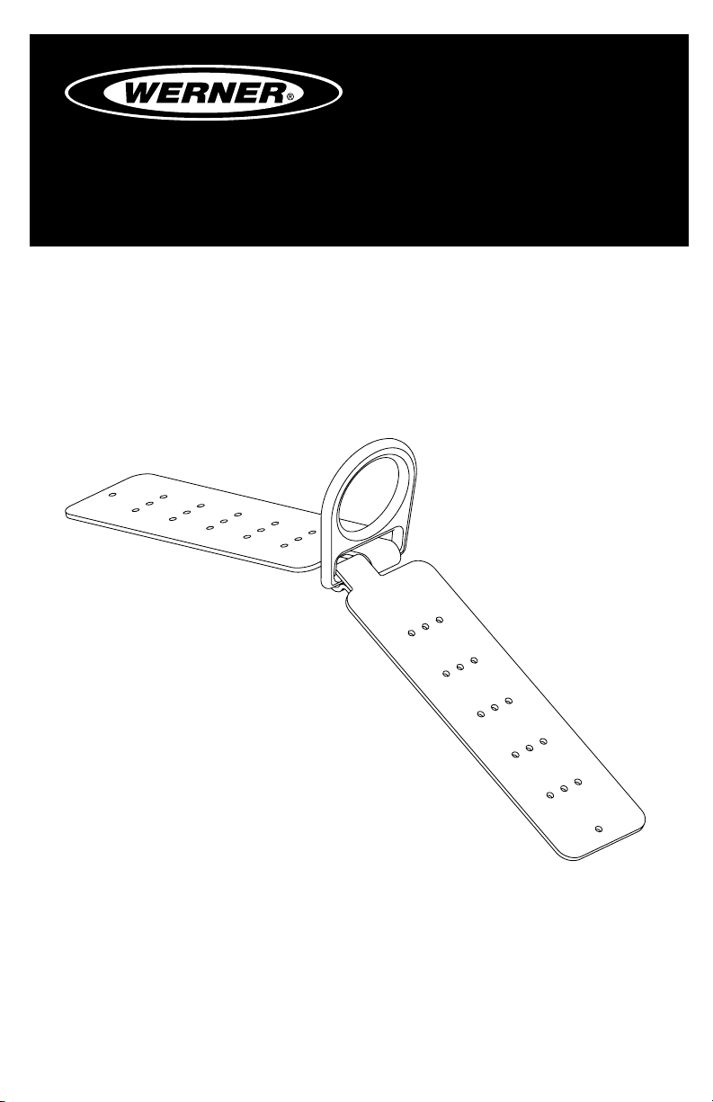
REUSEABLE ROOF ANCHOR
Complies with ANSI Z359.1-2007,
OSHA 1910 and 1926 requirements.
ANCLAJE REUTILIZABLE PARA
INSTALACIÓN EN TECHOS
Cumple con las normas ANSI Z359.1-2007,
OSHA 1910 y 1926.
(This manual applies to reusable roof anchor A210400.)
(Este manual aplica a la ancla de techo reusable A210400.)
Werner Fall Protection 724-588-2000
93 Werner Rd. 888-523-3371 toll free/ llamada gratuita
Greenville, PA 16125 888-456-8458 fax
Page 2
CAUTION!
If use of fall protection equipment is necessary then the work
environment is dangerous and potentially deadly. Werner Company
products are designed to eliminate as much of the hazard as possible
but can do that ONLY if they are used correctly. Use this equipment as
it was designed to be used, after appropriate training, under the direct
supervision of a competent person, according to the instructions
provided, and in accordance with OSHA and local safety regulations.
User MUST read and understand all cautions and instructions. Failure
to heed these guidelines could result in injury or even death. Please,
WORK SAFE! WORK SMART!
ENGLISH
Page 2
Page 3

REUSEABLE ROOF ANCHOR
USER INSTRUCTIONS
Contents
I. BEFORE USING THE REUSABLE ROOF ANCHOR ........................................ 4
a. Inspect ......................................................................................................................4
b. Compatibility ............................................................................................................6
c. Fall Protection Plan ..................................................................................................6
d. Training .....................................................................................................................8
II. ANCHOR INSTALLATION AND USE ...............................................................8
a. Making a Connection ...............................................................................................9
b. Anchorage Strength ..............................................................................................10
c. Installation Requirements .....................................................................................11
d. Roof Framing .......................................................................................................... 11
e. Roof Anchor Installation ....................................................................................... 11
f. Attaching Roof Anchor ..........................................................................................12
g. Removal of Roof Anchor .......................................................................................13
h. Connecting to the Roof Anchor ............................................................................13
III. USE WARNINGS, RESTRICTIONS AND CAUTIONS ................................... 13
a. Purpose ..................................................................................................................13
b. Rated Capacity .......................................................................................................14
c. Limitations ..............................................................................................................14
IV. LABELS/IDENTIFICATION/INSPECTION RECORDS .................................. 15
V. EQUIPMENT RECORDS ................................................................................16
VI. INSPECTION RECORDS .............................................................................. 16
ENGLISH
Page 3
Page 4
Warning:
This product is just one part of a personal fall arrest system. It must
be matched correctly with other components to form a complete and
functional system. The user must understand the function of each of
these components and follow the manufacturer’s instructions for use
for each. The user must be provided these instructions, should read
and follow them, and consult the competent person who will supervise
his work if he has any questions about any part of the instructions.
The employer must provide training in the proper use, inspection, and
maintenance of all components in the system, and these instructions
can be used as part of that training. The equipment should be used
ONLY in accordance with these instructions, local ordinances and
codes, the applicable OSHA and ANSI standards, and the employer’s
safety plan.
Alterations or misuse of this product or failure to follow instructions
may result in serious injury or death.
IF YOU HAVE ANY QUESTIONS ABOUT ANYTHING IN THESE
INSTRUCTIONS, THE EQUIPMENT, OR PROPER USE OF THE
EQUIPMENT, CONTACT WERNER CO. FOR MORE INFORMATION.
I. Before Using the Anchor
Before using this equipment the user should take certain steps to
ensure that it is in suitable condition and safe for use. Users must
read and understand these instructions. It is the employer’s obligation
to ensure that all users have been trained in safe work procedures as
well as in the use and limitations of fall protection equipment. All users
should be aware of and comply with all applicable OSHA, ANSI, CSA
and local or regional regulations concerning fall protection equipment
and its use.
a. Inspect
ENGLISH
Page 4
Examine all equipment thoroughly, daily before use by the user,
and periodically by a competent person who is not the user.
1. Before installation of this equipment, carefully inspect it to
assure it is in serviceable condition.
2. The roof anchor must be inspected by a competent person
other than the user at least annually. Record the results of
each formal inspection in the inspection log found on page 16.
Page 5

REUSEABLE ROOF ANCHOR
USER INSTRUCTIONS
Inspect the Roof Anchor for physical damage. Look carefully for
any signs of cracks, dents, or deformities in the metal. Check
for bending, the roof anchor legs should be at. Rivets or welds
should be securely attached and be free from cracks.
3. Inspect the Roof Anchor for signs of excessive corrosion.
4. Ensure the condition of the roof will support the Roof Anchor
load. An anchor connected to rotten or deteriorated wood
should not be used.
5. Ensure the Roof Anchor is still securely attached. If loose, do
not use.
6. Inspect each system component or subsystem per associated
manufacturer’s instructions.
7. Record the inspection date and results on the inspection log.
NOTE: The A210400 is designed as a multi-use anchor. New
16d nails 3” or longer, vinyl coated must be used for every
reinstallation.
8. Verify that all labels are intact, in place, and legible.
9. If inspection reveals a defective condition or abnormalities in
any of these areas, remove unit from service immediately. A
competent person should be consulted to determine if that item
is safe for continued use or if it should be destroyed.
10. IMPORTANT: If this equipment has been subjected to forces
resulting from the arrest of a fall, it must be immediately
removed from service.
b. Compatibility
Werner Co. equipment is designed for use with Werner Co. approved
components and subsystems only. Substitutions or replacements
made with non-approved components or subsystems may
jeopardize compatibility of equipment and may affect the safety and
reliability of the complete system.
Connectors are considered to be compatible with connecting
elements when they have been designed to work together in
such a way that their sizes and shapes do not cause their gate
mechanisms to inadvertently open regardless of how they become
oriented. Contact Werner Co. if you have any questions about
compatibility. Connectors (hooks, carabiners, and D-rings) must be
capable of supporting at least 5,000 lbs. (22.2kN). Connectors must
Page 5
ENGLISH
Page 6

be compatible with the anchorage or other system components.
Do not use equipment that is not compatible. Non-compatible
connectors may unintentionally disengage. Connectors must be
compatible in size, shape, and strength. Self locking snap hooks
and carabiners are required by ANSI Z359 and OSHA.
c. Fall Protection Plan
Plan your fall arrest or restraint system before starting your work.
Take into consideration all factors affecting your safety at any
time during use. The following list gives some important points to
consider when planning your system:
1. ANCHORAGE: Select an anchorage point that is rigid and
capable of supporting the required loads. Locate the roof anchor
in accordance with Section II.
2. PERSONAL FALL ARREST SYSTEM REQUIREMENT: PFAS’s
used with this roof anchor must meet applicable OSHA, state,
federal, and ANSI requirements. PFAS’s incorporating a full
body harness must be capable of arresting a worker’s fall with
maximum arresting force of no greater than 1,800 lbs. and
limiting the free fall distance to 6 feet or less. Reference ANSI
Z359 and OSHA requirements.
3. FREE FALL: PFAS’s must be rigged to limit any free fall to a
maximum of 6 feet (OSHA and ANSI Z359.1). Restraint systems
must be rigged such that no vertical free fall is possible. Avoid
working above your anchorage level since an increased free fall
distance will result.
4. RESTRAINT SYSTEMS: Restraint systems must meet
applicable state and federal requirements.
ENGLISH
Page 6
5. FALL CLEARANCE: Should a fall occur, there must be sufficient
clearance in the fall area to arrest the fall before striking the
ground or other objects. The actual clearance required is
dependent upon the type of fall arrest connecting subsystem
used (energy absorbing lanyard, self retracting lifeline, etc.).
Refer to manufacturer’s instructions for fall clearance information.
Page 7
REUSEABLE ROOF ANCHOR
USER INSTRUCTIONS
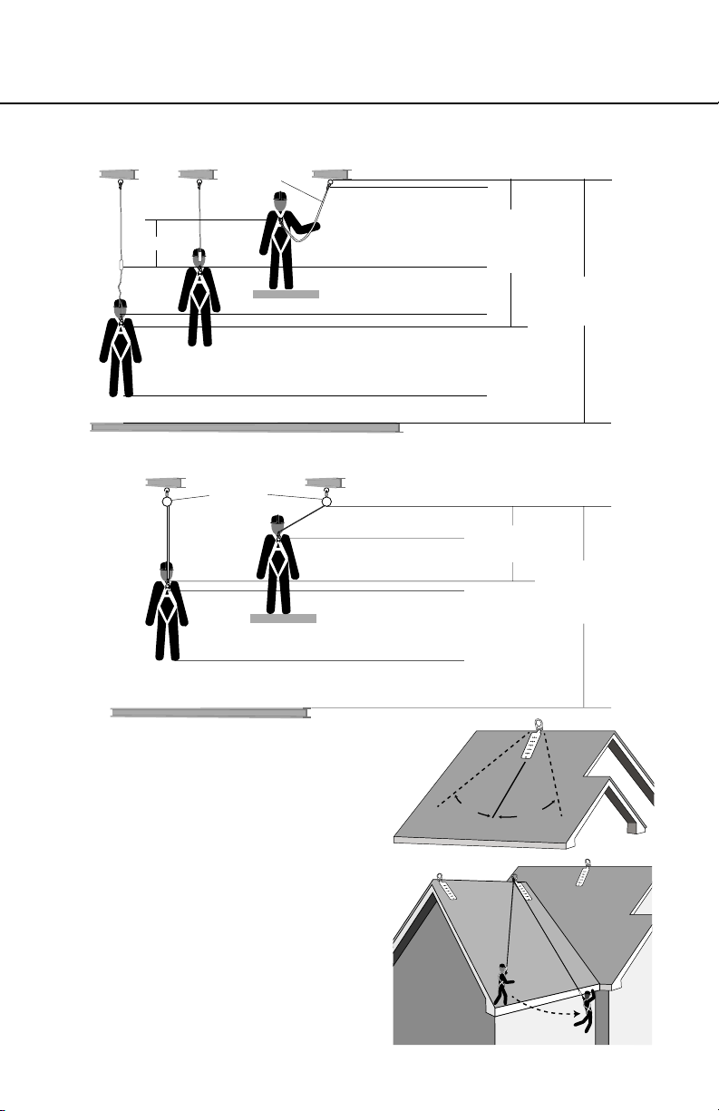
Fall distance for shock absorbing lanyards
Energy
Free Fall
Absorbing
Lanyard
Working Level
Length of Anchorage Connector
6 ft.
Length of Lanyard
4 ft.
Deceleration Free Fall Distance
1 ft. Harness Stretch
5 ft.
To Worker’s Back D-Ring
Total Fall
Distance
(Free Fall +
Deceleration)
11 ft.
Total Estimated
Fall Distance
18 ft.
Lower Level or Obstruction
2 ft.
Safety Factor
Fall distance for self-retracting lifeline
Self Retracting
Lifeline
Lower Level or Obstruction
Working Level
Bottom of Retractable Lifeline
2 ft.
Maximum Free Fall
2.5 ft.
Maximum Deceleration
1 ft. Harness Stretch
5 ft.
To Worker’s Back D-Ring
2 ft.
Safety Factor
6. SWING FALLS: Swing falls
occur when the anchor is
not directly above the point
where a fall occurs. The
force of striking an object
while swinging can be great
and cause serious injury.
Minimize swing falls by
working as directly below the
anchorage as possible (the
worker must be positioned
within 30 degrees of the roof
anchor). It is acceptable to
captivate a lifeline (i.e. rope
grab system) to an anchorage
Maximum Arrest
Distance (per ANSI)
4.5 ft.
30°
Working Range
Total Estimated
Fall Distance
12.5 ft.
Roof Anchor
30°
ENGLISH
Page 7
Page 8
close to the work area with a carabiner. Do not captivate the lifeline
of a self retracting lifeline as this may affect the performance of its
internal braking.
7. SHARP EDGES: Avoid working where the connecting subsystem
(i.e. shock absorbing lanyard, self retracting lifeline, full body
harness, etc.) or other components will be in contact with, or
abrade against, unprotected sharp edges. Do not the loop lanyard
around small diameter structural members. If working with
equipment near sharp edges is unavoidable, protection against
cutting must be provided by using a heavy pad or other means
over the exposed sharp edge.
8. RESCUE: Should a fall occur, the user (employer) must have a
rescue plan. If a worker falls and is forced to remain suspended for
any length of time, physical damage to the body or even death can
result. For this reason Werner, OSHA, ANSI, CSA and most local
regulations require that a rescue plan and the means to implement
the rescue plan are in place before use of this equipment.
9. AFTER A FALL: Any equipment which has been subjected to the
force of arresting a fall must be removed from service immediately.
d. Training
OSHA, ANSI, and most local ordinances require that workers using
this product receive adequate training before use of this product.
These instructions and their entire contents should be a part of that
training.
II. Anchor Installation and Use
Warning:
Do not alter or intentionally misuse this equipment. Consult with
Werner Co. if using this equipment with components or subsystems
other than those described in this manual. Some subsystem and
component combinations may interfere with the operation of this
equipment. Use caution when using this equipment around moving
machinery, electrical hazards, chemical hazards, and sharp edges.
Warning:
Do not use this system if you are unable to tolerate the impact of
a fall arrest. Age and tness can seriously affect your ability to
withstand a fall. Pregnant women and minors must not use
ENGLISH
this equipment.
Page 8
Page 9
REUSEABLE ROOF ANCHOR
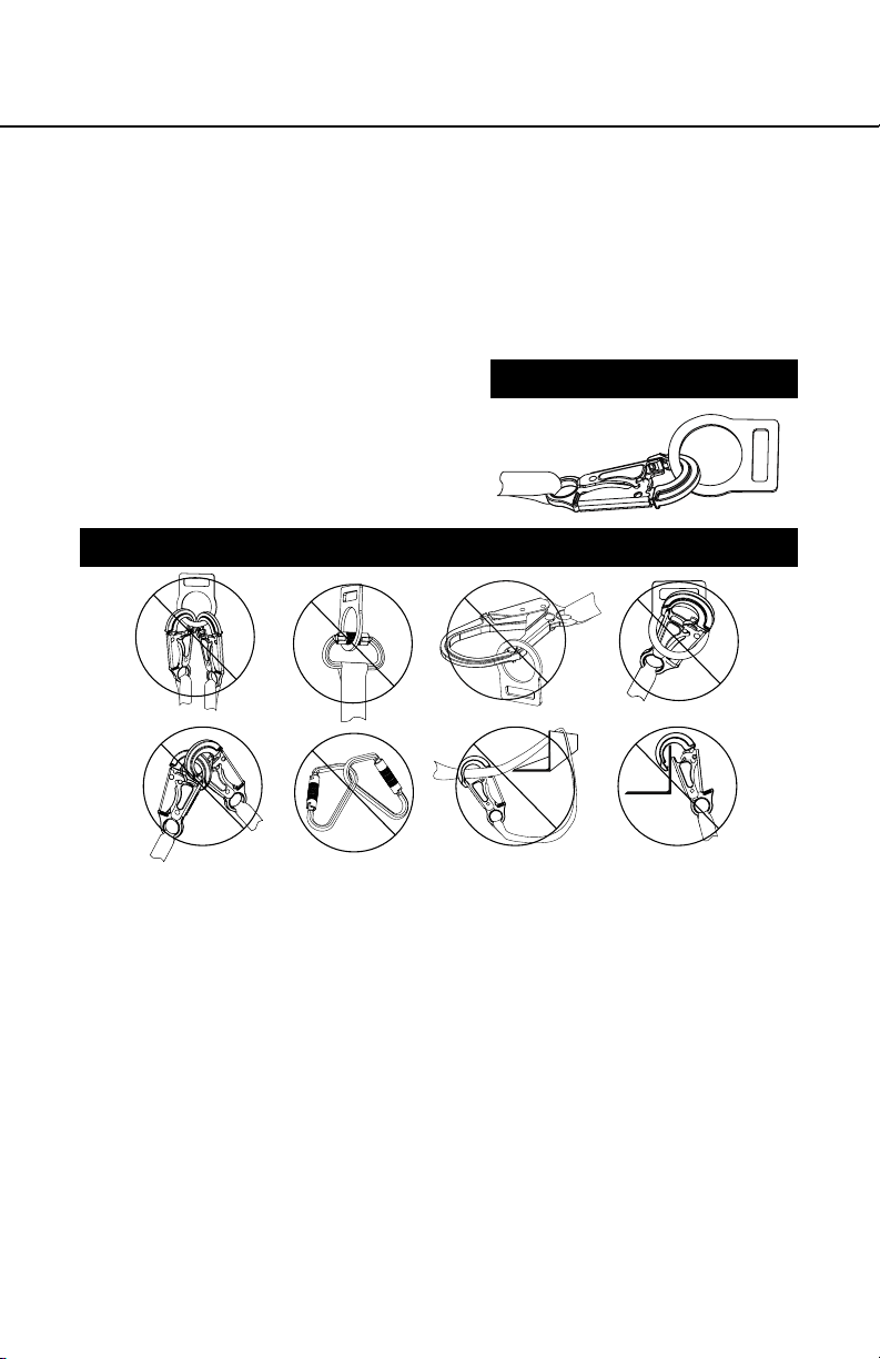
a. Making Connections:
1. Only use self-locking snap hooks and carabiners with this
equipment. Only use connectors that are suitable to each
application. Ensure all connections are compatible in size,
shape and strength. Do not use equipment that is not
compatible. Ensure all connectors are fully closed and locked.
2. Werner Co. connectors (snap
hooks and carabiners) are
designed to be used only as
specied in each product’s
user’s instructions. See for
inappropriate connections.
INAPPROPRIATE CONNECTIONS
A. B.
NO! NO! NO! NO!
D. E. F.
PROPER CONNECTIONS
USER INSTRUCTIONS
C.
NO!NO!NO!NO!
Werner Co. snap hooks and carabiners should NOT be
connected:
i. to a D-ring to which another connector is attached.
ii. in a manner that would result in a load on the gate. If the
connecting element that a snaphook or carabiner attaches
to is undersized or irregular in shape, a situation could occur
where the connecting element applies a force to the gate of
the snaphook or carabiner. This force may cause the gate
(of either a self-locking or a non-locking snaphook) to open,
allowing the snaphook or carabiner to disengage from the
connecting point.
NOTE: Large throat opening snap hooks should not be
connected to standard size D-rings or similar objects which
will result in a load on the gate if the hook or D-ring twists
or rotates. Large throat snap hooks are designed for use on
Page 9
ENGLISH
Page 10

xed structural elements such as rebar or cross members
that are not shaped in a way that can capture the gate of
the hook.
iii. in a false engagement, where features that protrude from
the snap hook or carabiner catch on the anchor and without
visual conrmation seems to be fully engaged to the anchor
point.
iv. to each other.
v. directly to webbing or rope lanyard or tie-back (unless
the manufacturer’s instructions for both the lanyard and
connector specically allow such a connection).
vi. to any object which is shaped or dimensioned such that the
snap hook or carabiner will not close and lock, or where roll-
out could occur.
3. Do not pass the lanyard or lifeline through the roof anchor D-ring
and hook back into the lanyard or lifeline. When connecting,
make sure the connections are fully closed and locked.
4. When using an energy-absorbing lanyard, connect the energy
absorber “pack” end to the harness.
5. When using a self-retracting lifeline, make sure the device is
properly positioned so that the retraction is not hindered.
6. Always protect the lifeline/lanyard from abrading against sharp
or abrasive surfaces on the roof.
ENGLISH
Page 10
b. Anchorage Strength
Depending on the application, the anchorage to which the roof
anchor is installed must meet strengths as given below:
1. FALL ARREST: Roof anchors installed for fall arrest applications
must be attached to a roof member capable of sustaining
static loads in the direction(s) permitted by the Personal
Fall Arrest System (PFAS) when in use of at least 3,600 lbs.
(16kN) when certication exists (reference ANSI Z359.1 for
certication denition); or 5,000 lbs. (22.2kN) in absence of
certication. When more than one roof anchor is installed to a
roof structure, the strengths given above must be met at each
roof anchor’s installation point independently. EXAMPLE: If two
roof anchors are installed onto a roof structure, each anchor
location must be independently capable of supporting 5,000 lbs.
Page 11
REUSEABLE ROOF ANCHOR
USER INSTRUCTIONS
(or 3,600 lbs. with certication). From OSHA 1926.500 and
1910.66: Anchorages used for attachment of a personal fall
arrest system shall be independent of any anchorage being
used to support or suspend platforms, and must support at
least 5,000 lbs. per user attached; or be designed, installed, and
used as part of a complete personal fall arrest system which
maintains a safety factor of at least two, and is supervised by a
qualied person.
2. RESTRAINT: Roof anchors installed for restraint applications
must be attached to a roof member capable of sustaining a static
load of at least 3,000 lbs. applied in any direction permitted by
the restraint system when in use. Each roof anchor installation
must be independently capable of sustaining this load.
c. Installation Requirements
ROOF ANCHOR SITE PLAN: Before starting the roof construction,
a plan should be established as to where the roof anchors will be
installed, and when during the construction process they may be
used. The following are guidelines on locating roof anchors:
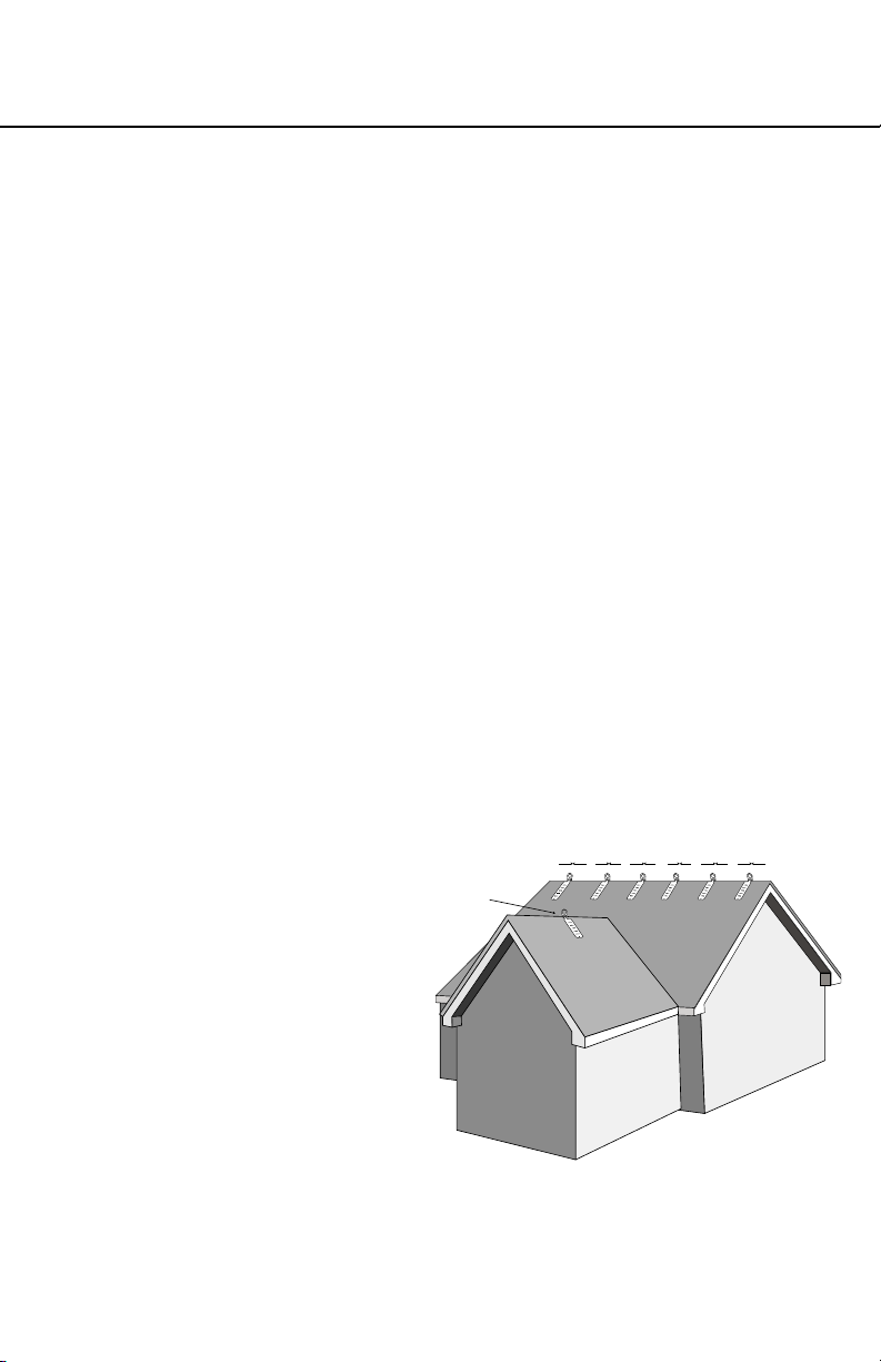
1. The roof anchor should be located at the roof peak (when
possible) and at least 6 feet from any exposed roof edge. On
very small roof areas, locate the roof anchor as far from the roof
edge as possible.
2. Do not install
roof anchors on
unsupported roof
At least one anchor
on hip roof
structures, such
as eaves or gable
overhangs. Do not
install roof anchors on
facia boards.
3. Roof anchors should
be installed at 8 foot
intervals along the
roof ridge. Hip roofs
require a roof anchor
on each hip face.
4. On long low pitched roofs, multiple roof anchors should be
installed along the gable ends (6 feet from the edge) to reduce
swing fall hazards.
8’ 8’ 8’ 8’ 8’ 6’6’
ENGLISH
Page 11
Page 12

d. Roof Framing
Roof framing members to which the roof anchors are attached
must be in good condition. Members must be free of splits, cracks,
large knots, or defects that may
weaken the member. Do not
attach the roof anchor to rotted or
deteriorated wood.
e. Roof Anchor Installation:
Roof anchors must be installed
in accordance with the previously
discussed site plan. Site work
rules must be followed regarding
when an installed roof anchor is
ready for use (i.e. after sheathing
is in place).
f. Attaching the Roof Anchor
Spread the anchor base legs apart to match the surface it will be
mounted on, either a roof peak or a at surface. Position the anchor
on the roof such that the 12 nail holes along the center of the legs
are over (framing) member. Then, push down to minimize any gap
between the anchor and the sheathing and nail. Use only 16d
nails 3” or longer to install the anchor (6 per leg into the rafters and
sheathing). Install all 12 nails.
Never attach the roof anchor with the legs still together (legs must
be spread apart).
Warning:
The A210400 roof anchor must be positioned on top of previously
secured roof sheathing (do not attach directly to rafter or truss
member). All 12 nails must be installed. If the roof anchor is not
installed properly, it will not hold the rated loads and serious injury or
death could occur.
Warning:
Use only 16d nails which have a complete head. Do not use nails from
nail guns.
ENGLISH
Page 12
Page 13

REUSEABLE ROOF ANCHOR
USER INSTRUCTIONS
g. Removal of Roof Anchor
Remove the roof anchor prior to shingling the area with
the anchor. To remove it, pry off the anchor from the roof.
NOTE: The A210400 is designed as a multi-use anchor. New 16d
nails must be used for every reinstallation.
h. Connecting to the Roof Anchor
Connection to the installed roof anchor may be made using a self
locking snap hook or self locking and self closing carabineer only.
Do not use a knot to connect a lifeline to the roof anchor.
III. Use Warnings, Restrictions and Cautions
a. Purpose
This device is designed to be used as a temporarily installed (not
for permanent installation) anchorage connector on wood frame
structures. This anchorage connector may be used as part of a
personal fall arrest or restraint system. Do not attach a lifeline
between two or more roof anchors (i.e. horizontal lifeline system).
Do not hang, lift or support tools or equipment from this roof anchor
or attach guylines for antennas, phone lines, etc.
1. FALL ARREST APPLICATION: In this application, the roof
anchor is used as part of a complete fall arrest system. Such
systems typically include a full body harness and some form of
connecting subsystem, such as an energy absorbing lanyard.
Maximum permissible free fall is 6 feet. This type of system is
used where a free fall is possible before the fall is arrested.
2. RESTRAINT APPLICATION: In this application, the roof anchor
is used as part of a complete restraint system. Such systems
typically include a full body harness and a lanyard or restraint
line used to restrain or tether the user from reaching a hazard
(i.e. leading edge roof work). This type of system is used where
no vertical free fall is possible.
b. Rated Capacity
1. Capacity: 310 lbs. For one person with a combined weight
(person, clothing, tools, etc.) of no more than 310 lbs. Only one
personal protective system may be connected to the roof anchor
at any time.
Page 13
ENGLISH
Page 14

ENGLISH
2. Minimum Breaking Strength: 5000 lbs. when loaded within the
loading direction limitations. This anchor satises the OSHA
and ANSI strength requirements when used in accordance
with OSHA, ANSI, CSA standards, local regulations and the
manufacturer’s instructions.
c. Limitations
The following application limitations must be recognized and
considered before using this product:
1. ROOF STRUCTURE: This anchorage connector is intended to
be installed on wood framed structures capable of meeting the
anchorage strength requirements. Consult Werner Co. before
using these roof anchors on any other roof material.
2. PERSONAL FALL ARREST SYSTEM (PFAS): PFAS’s selected
for use with this roof anchor must meet the system performance
and other criteria.
3. FREE FALL: PFAS’s used with these roof anchors must be
rigged in such a way as to limit the free fall to a maximum of
6 feet. See associated connecting subsystem manufacturer’s
instructions for further information.
4. FALL CLEARANCE : Make certain that enough clearance exists
in your fall path to prevent striking an object. The amount of
clearance needed is dependent upon the type of connecting
subsystem used (energy absorbing lanyard, self retracting
lifeline, etc.), and the anchorage location. Refer to manufacturer’s
instructions of the connecting subsystem or component for more
information on fall clearance.
5. RESTRAINT SYSTEMS: Restraint systems selected for use with
this roof anchor must meet the requirements given.
6. CORROSION: Use near sea water or other corrosive
environments may require more frequent inspections or servicing
(replacement) to assure corrosion damage is not affecting the
performance of the product.
7. CHEMICAL HAZARDS: Solutions containing acids, alkali, or
other caustic chemicals, especially at elevated temperatures,
may cause damage to this equipment. Consult Werner Co.
if doubt exists concerning installing this equipment where
chemical hazards are present.
Page 14
Page 15

REUSEABLE ROOF ANCHOR
USER INSTRUCTIONS
8. ELECTRICAL HAZARDS: Do not install roof anchors where
they or the user may come into contact with electrical power
lines.
IV. Labels/Identication/Inspection Records
a. All products should be inspected by the user thoroughly before
each use. Additional inspections by a competent person other than
the user should be conducted at intervals of no less than one year.
That interval should be shortened any time the product is used in a
harsh environment or is exposed to conditions such as chemicals,
abrasion, heat or any other factor that could affect the strength of
any of the materials or components.
b. This manual should always accompany the product, or be on le
with the employer for access when needed. Record the identication
details for the anchor and record the inspections in the inspection
log, on page 16. It is important to keep this log current, complete,
and available as needed.
Page 15
ENGLISH
Page 16

V. Equipment Record
PART NUMBER
SERIAL NUMBER
DATE
MANUFACTURED
PURCHASE DATE
ASSIGNED TO
SPECIFICATIONS
Werner Roof Anchor
Certied to meet ANSI Z359.1-2007, and OSHA 1910 and 1926 standards
and regulations for the subsystem components of a complete personal
fall arrest system.
Individually bar coded model and serial numbers, location and date of
manufacture are on product label.
VI. Inspection Record
INSPECTION RECORD
DAT E INSPECTOR PASS/FAILDAT E INSPECTOR PASS/FAIL
ENGLISH
Page 16
Page 17

REUSEABLE ROOF ANCHOR
USER INSTRUCTIONS
Id label
Warning label
Page 18

¡PRECAUCIÓN!
Si el uso de equipos de protección contra caídas es necesario, entonces el
ambiente de trabajo es peligroso y potencialmente mortal. Los productos
Werner Company están diseñados para eliminar peligros tanto como sea
posible, pero SÓLO si estos productos se utilizan correctamente. Utilice este
equipo tal como fue diseñado para usarse, después de una capacitación
apropiada, bajo la supervisión directa de una persona calicada, de acuerdo
con las instrucciones suministradas, y de acuerdo con las regulaciones OSHA
y las regulaciones de seguridad locales. El usuario DEBE leer y entender todas
las precauciones e instrucciones. No tener en cuenta estas directrices podría
resultar en lesiones o incluso la muerte. Por favor, ¡TRABAJE DE MANERA
SEGURA! ¡TRABAJE DE MANERA INTELIGENTE!
ESPAÑOL
Página 18
Page 19

ANCLAJE REUTILIZABLE PARA INSTALACIÓN EN TECHO
INSTRUCCIONES PARA EL USUARIO
Contenido
I. ANTES DE UTILIZAR EL ANCLAJE REUTILIZABLE PARA
INSTALACIÓN EN TECHO .............................................................................20
a. Inspeccione ............................................................................................................20
b. Compatibilidad .......................................................................................................21
c. Plan de protección contra caídas .........................................................................22
d. Capacitación ...........................................................................................................24
II. INSTALACIÓN Y USO DEL ANCLAJE ........................................................... 24
a. Realización de una conexión ................................................................................25
b. Resistencia del anclaje ..........................................................................................26
c. Requisitos de instalación ......................................................................................27
d. Marcos del techo ....................................................................................................27
e. Instalación del anclaje en techo ...........................................................................27
f. Sujeción del anclaje en techo ...............................................................................28
g. Remoción del anclaje en techo .............................................................................29
h. Conexión al anclaje en techo
III. TENGA EN CUENTA LAS ADVERTENCIAS, RESTRICCIONES
Y PRECAUCIONES ........................................................................................ 29
a. Propósito ...............................................................................................................29
b. Capacidad nominal ................................................................................................30
c. Limitaciones ...........................................................................................................30
................................................................................29
IV. ETIQUETAS/IDENTIFICACIÓN/REGISTROS DE INSPECCIÓN ..................31
V. REGISTROS DE EQUIPOS ............................................................................ 32
VI. REGISTROS DE INSPECCIÓN ..................................................................... 32
Página 19
ESPAÑOL
Page 20

Advertencia:
Este producto es sólo una parte de un sistema personal de detención de
caídas. Éste debe combinarse correctamente con otros componentes para
conformar un sistema completo y funcional. El usuario debe entender la
función de cada uno de estos componentes y seguir las instrucciones del
fabricante para el uso de cada componente. El usuario debe recibir estas
instrucciones, debe leerlas y seguirlas, y consultar a la persona calicada que
supervisará su trabajo si tiene alguna pregunta acerca de cualquier parte de
las instrucciones. El empleador debe proporcionar capacitación sobre el uso
apropiado, inspección y mantenimiento de todos los componentes del sistema,
y estas instrucciones pueden utilizarse como parte de esa capacitación. El
equipo SÓLO debe utilizarse de acuerdo con estas instrucciones, ordenanzas
y códigos locales, las normas OSHA y ANSI aplicables, y el plan de seguridad
del empleador.
Las alteraciones o uso incorrecto de este producto, o no seguir estas
instrucciones, podría resultar en lesiones graves o la muerte.
SI USTED TIENE ALGUNA PREGUNTA ACERCA DE ALGO DE ESTAS
INSTRUCCIONES, EL EQUIPO O EL USO APROPIADO DEL EQUIPO,
COMUNÍQUESE CON WERNER CO. PARA OBTENER MÁS INFORMACIÓN.
I. Antes de utilizar el anclaje
Antes de utilizar este equipo, el usuario debe realizar ciertos pasos para
garantizar que éste está en condiciones apropiadas y es seguro para su uso.
Los usuarios deben leer y entender estas instrucciones. Es obligación del
empleador garantizar que todos los usuarios hayan recibido capacitación
sobre los procedimientos de trabajo seguros y también sobre el uso y
limitaciones de los equipos de protección contra caídas. Todos los usuarios
deben estar informados acerca de y cumplir todas las normas OSHA, ANSI,
CSA y las normas locales o regionales relacionadas con los equipos de
protección contra caídas y su uso.
a. Inspeccione
Todo el equipo debe ser examinado completamente, diariamente antes
del uso, por parte del usuario; y periódicamente por parte de una persona
calicada que no sea el usuario.
1. Before installation of this equipment, carefully inspect it to assure it is
in serviceable condition.
2. El anclaje para instalación en techo debe ser inspeccionado por
una persona capacitada diferente al usuario, anualmente como
ESPAÑOL
Página 20
mínimo. Registre los resultados de cada inspección formal en el
registro de inspección mostrado en la página 16. Inspeccione el
Page 21

ANCLAJE REUTILIZABLE PARA INSTALACIÓN EN TECHO
INSTRUCCIONES PARA EL USUARIO
Anclaje para Instalación en Techo en busca de daños físicos. Revise
cuidadosamente en busca de cualquier señal de grietas, abolladuras
o deformidades en el metal. Revise en busca de dobladura, las patas
del anclaje para instalación en techo debe estar planas. Los remaches
o soldaduras deben estar sujetados de manera rme y sin grietas.
3. Inspeccione el Anclaje para Instalación en Techo en busca de señales
de corrosión excesiva.
4. Verique la condición del techo que soportará la carga del anclaje. No
debe utilizarse un anclaje conectado a madera podrida o deteriorada.
5. Verique que el Anclaje en Techo sigue sujetado de manera rme. Si
está ojo, no lo utilice.
6. Inspeccione cada componente del sistema o subsistema según las
instrucciones del fabricante respectivo.
7. Registre la fecha y resultados de la inspección en el registro de
inspección.
NOTA: El A210400 está diseñado como anclaje multiuso. Deben utilizarse
clavos 16d nuevos de 3” ó más, con recubrimiento de vinilo, para cada
reinstalación.
8. Verique que todas las etiquetas están intactas, en su sitio, y son
legibles.
9. Si la inspección revela una condición defectuosa o anormalidades
en cualquiera de estas áreas, retire inmediatamente del servicio la
unidad. Debe consultarse a una persona capacitada para determinar
si ese elemento es seguro para uso continuado o si debe destruirse.
10. IMPORTANTE: Si este equipo ha sido sometido a las fuerzas resultantes
de una detención de caída, éste debe retirarse inmediatamente del
servicio.
b. Compatibilidad
Los equipos Werner Co. están diseñados para uso sólo con componentes
y subsistemas aprobados por Werner Co. Las sustituciones o reemplazos
realizados con componentes o subsistemas no aprobados podrían
arriesgar la compatibilidad del equipo y podrían afectar la seguridad y
conabilidad del sistema completo.
Los conectores se consideran compatibles con los elementos conectivos
cuando éstos han sido diseñados para trabajar en conjunto de tal manera
que sus tamaños y formas no causen que sus mecanismos de cierre
se abran inadvertidamente sin importar la manera como se orienten.
Comuníquese con Werner Co. si usted tiene alguna pregunta acerca de la
compatibilidad. Los conectores (ganchos, argollas rectangulares metálicas
y los anillos en ‘D’) deben ser capaces de soportar 5.000 lbs. (22,2kN)
Página 21
ESPAÑOL
Page 22

como mínimo. Los conectores deben ser compatibles con el anclaje u otros
componentes del sistema. No utilice equipos que no sean compatibles.
Los conectores no compatibles pueden desengancharse accidentalmente.
Los conectores deben ser compatibles en tamaño, forma y resistencia. Las
normas ANSI Z359 y OSHA requieren argollas metálicas y ganchos de
cierre resortado auto-asegurables.
c. Plan de protección contra caídas
Planee su sistema de detención o evitamiento de caídas antes de iniciar
su trabajo. Tenga en cuenta todos los factores que afectan su seguridad en
cualquier momento durante el uso. La siguiente lista proporciona algunos
puntos importantes que deben considerarse al planear su sistema:
1. ANCLAMIENTO: Seleccione un punto de anclamiento que sea rígido
y capaz de soportar las cargas requeridas. Ubique el anclaje para
instalación en techo de acuerdo con la Sección II.
2. REQUISITO PARA LOS SISTEMAS PERSONALES DE DETENCIÓN
DE CAÍDAS: Los Sistemas Personales de Detención de Caídas (SPDC)
utilizados con este anclaje para instalación en techo deben cumplir
las normas OSHA, estatales, federales y ANSI aplicables. Los SPDC’s
que incorporan un arnés para cuerpo completo deben ser capaces de
detener la caída de trabajadores con una fuerza de detención máxima
no superior a 1.800 lbs. y limitar la distancia de caída libre a 1.83 m (6
pies) o menos. Consulte las normas ANSI Z359 y OSHA.
3. CAÍDA LIBRE: Los SPDC’s deben instalarse para limitar cualquier
caída libre a un máximo de 1.83 m (6 pies) (OSHA y ANSI Z359.1).
Los sistemas de evitamiento de caídas deben instalarse de modo que
no sea posible una caída libre vertical. Evite trabajar por encima de su
nivel de anclaje ya que esto resultaría en una distancia de caída libre
aumentada.
4. SISTEMAS DE EVITAMIENTO DE CAÍDAS: Los sistemas de
evitamiento de caídas deben cumplir los requisitos estatales y federales
aplicables.
5. ESPACIO LIBRE DE CAÍDA: Si ocurre una caída, debe haber suciente
espacio libre en el área de caída para detener la caída antes de golpear
el suelo u otros objetos. El verdadero espacio libre requerido depende
del tipo de subsistema conectivo de detención de caídas que se utilice
(cuerda absorbedora de energía, cuerda salvavidas auto-retráctil, etc.).
Consulte las instrucciones del fabricante para obtener información
sobre el espacio libre de caída.
ESPAÑOL
Página 22
Page 23

ANCLAJE REUTILIZABLE PARA INSTALACIÓN EN TECHO
Distancia de caída total
INSTRUCCIONES PARA EL USUARIO
Distancia de caída para las cuerdas absorbedoras de impacto
Cuerda
Caída libre
absorbedora
de energía
Nivel de trabajo
Longitud del conector del anclaje
1.83 m (6 pies)
Longitud de la cuerda
1.22 m (4 pies)
Distancia de caída libre con desaceleración
0.31 m (1 pie) de alargamiento del arnés
1.5 m (5 pies)
al anillo en “D” de espalda del trabajador
Distancia de
caída total
(Caída libre +
Desaceleración)
(11 pies)
3.35 m
(Caída libre +
Desaceleración)
3.35 m (11 pies)
Nivel inferior u obstrucción
0.6 m (2 pies)
Factor de seguridad
Distancia de caída para cuerda salvavidas auto-retráctil
Cuerda salvavidas
auto-retráctil
Nivel de trabajo
Nivel inferior u obstrucción
6. CAÍDAS TIPO COLUMPIO: Las
caídas tipo columpio ocurren cuando
el anclaje no está directamente
encima del punto donde ocurre
una caída. La fuerza de golpear
un objeto mientras sucede un
movimiento pendular puede ser
grande y causar lesiones graves.
Minimice las caídas tipo columpio
trabajando tan directamente debajo
del anclaje como sea posible (el
trabajador debe colocarse dentro
de 30 grados del anclaje instalado
en techo). Es aceptable sujetar
una cuerda salvavidas (es decir,
sistema de agarre de cuerda) a un
Parte inferior de la unidad de cuerda salvavidas retráctil
0.6 m (2 pies)
Caída libre máxima
0.8 m (2.5 pies)
Desaceleración máxima
0.31 m (1 pie) de alargamiento del arnés
1.5 m (5 pies)
al anillo en “D” de espalda del trabajador
0.6 m (2 pies)
Factor de seguridad
Distancia máxima para
detención (según ANSI)
1.4 m (4.5 pies)
30°
Rango de trabajo
Distancia de caída
estimada total
3.8 m (12.5 pies)
Anclaje en techo
30°
Página 23
ESPAÑOL
Page 24

anclajepad cercano al área trabajo con una argolla rectangular metálica. No
sujete la cuerda de una cuerda salvavidas auto-retráctil ya que esto podría
afectar el funcionamiento de su frenado interno.
7. BORDES FILOSOS: Evite trabajar donde el subsistema conectivo (es
decir, cuerda absorbedora de impacto, cuerda salvavidas auto-retráctil,
arnés de cuerpo completo, etc.) u otros componentes harán contacto
con, o se desgastarán contra, bordes losos expuestos. No enrolle la
cuerda alrededor de miembros estructurales de diámetro pequeño. Si no
se puede evitar trabajar con los equipos cerca de bordes losos, debe
suministrarse protección contra cortes utilizando una almohadilla gruesa
u otros medios sobre el borde loso expuesto.
8. RESCATE: Si ocurre una caída, el usuario (empleador) debe tener un
plan de rescate. Si un trabajador cae y queda obligado a permanecer
suspendido durante cualquier período de tiempo, podría producirse daño
físico o incluso la muerte. Por este motivo, Werner, las regulaciones de
OSHA, ANSI, CSA, y la mayoría de las regulaciones locales exigen la
existencia de un plan de rescate y los medios para ejecutar un plan de
rescate, antes del uso de este equipo.
9. DESPUÉS DE UNA CAÍDA: Cualquier equipo que ha sido sometido a una
fuerza de detención de caída debe retirarse inmediatamente el servicio.
d. Capacitación
Las regulaciones OSHA, ANSI, y la mayoría de las regulaciones locales
exigen que los trabajadores que utilicen este producto deben recibir
capacitación adecuada antes del uso de este producto. Estas instrucciones y
su contenido completo deben ser parte de esa capacitación..
II. Instalación y uso del anclaje
Advertencia:
No altere ni utilice incorrectamente intencionalmente este equipo. Consulte
con Werner Co. si este equipo se utilizará con componentes o subsistemas
diferentes a los descritos en este manual. Algunos subsistemas y
combinaciones de componentes podrían interferir con la operación de este
equipo. Tenga precaución al utilizar este equipo alrededor de máquinas en
movimiento, peligros eléctricos, peligros químicos y bordes losos.
Advertencia:
No utilice este sistema si usted no puede tolerar el impacto de una
detención de caída. La edad y la aptitud física pueden afectar seriamente
su capacidad para soportar una caída. Las mujeres embarazadas y los
ESPAÑOL
menores de edad no deben utilizar este equipo.
Página 24
Page 25

ANCLAJE REUTILIZABLE PARA INSTALACIÓN EN TECHO
INSTRUCCIONES PARA EL USUARIO
a. Realización de las conexiones:
1. Con este equipo, sólo utilice argollas rectangulares metálicas y
ganchos de cierre resortado auto-asegurables. Sólo utilice conectores
que sean apropiados para cada aplicación. Verique que todas las
conexiones son compatibles
en tamaño, forma y resistencia.
No utilice equipos que no sean
compatibles. Verique que todos
conectores están totalmente
cerrados y asegurados.
CONEXIONES INAPROPIADAS
A. B.
NO! NO! NO! NO!
D. E. F.
CONEXIONES APROPIADAS
C.
NO!NO!NO!NO!
2. Los conectores Werner Co. (ganchos de cierre resortado y argollas
rectangulares metálicas) están diseñados para utilizarse únicamente
según se especica en las instrucciones para cada usuario del
producto. Vea para conocer las conexiones inapropiadas. Los ganchos
de cierre resortado y las argollas rectangulares metálicas de Werner
Co. NO deben conectarse:
i. a un anillo en ‘D’ al cual está sujetado otro conector.
ii. de tal manera que se produciría carga sobre el cierre. Si el elemento
conectivo al cual se sujeta un gancho de cierre resortado o una
argolla rectangular metálica es de tamaño inferior o tiene forma
irregular, podría ocurrir un problema cuando el elemento conectivo
aplique una fuerza al cierre del gancho de cierre resortado o la
argolla rectangular metálica. Esta fuerza podría causar que se
abra el cierre (de un gancho de cierre resortado auto-asegurable
o no-asegurable), permitiendo que el gancho de cierre resortado
o la argolla rectangular metálica se desenganche del punto de
conexión.
NOTA: Los ganchos de cierre resortado que se abren hasta una
garganta grande no deben conectarse a anillos en ‘D’ de tamaño
estándar u objetos similares, lo cual resultará en una carga sobre
Página 25
ESPAÑOL
Page 26

ESPAÑOL
Página 26
el cierre si el gancho o anillo en ‘D’ gira o rota. Los ganchos de
cierre resortado de garganta grande están diseñados para uso
en elementos estructurales jos tales como barras de refuerzo o
travesaños que no tengan una forma que pueda atrapar el cierre
del gancho.
iii. en un enganche falso, donde las características que sobresalen
del gancho de cierre resortado o la argolla rectangular metálica
se agarran al anclaje, y sin conrmación visual parece estar
totalmente enganchado al punto de anclaje.
iv. uno al otro.
v. directamente a una correa tejida o cuerda o amarre (a menos que
las instrucciones del fabricante de la cuerda y el conector permitan
especícamente dicha conexión).
vi. a cualquier objeto que tenga una forma o dimensiones tales que el
gancho de cierre resortado o la argolla rectangular metálica no se
cierren ni aseguren, y pudiera ocurrir rodaje.
3. No pase la cuerda o cuerda salvavidas a través del anillo en ‘D’
del anclaje en techo y enganche de regreso en la cuerda o cuerda
salvavidas. Al conectar, verique que las conexiones están totalmente
cerradas y aseguradas.
4. Al utilizar una cuerda absorbedora de energía, conecte el extremo con
“paquete” absorbedor de energía al arnés.
5. Al utilizar una cuerda salvavidas auto-retráctil, verique que el
dispositivo está posicionado apropiadamente de modo que no se
restrinja la retracción.
6. Siempre proteja la cuerda salvavidas/cuerda contra desgaste con
supercies losas o abrasivas en el techo.
b. Resistencia del anclaje
Dependiendo de la aplicación, el anclamiento al cual se instala el anclaje
en techo debe cumplir las resistencias según se indican a continuación:
1. DETENCIÓN DE CAÍDA: Los anclajes de instalación en techo para
aplicaciones de detención de caídas deben sujetarse a un componente
de techo capaz de soportar cargas estáticas, en la dirección(es)
permitida por el Sistema Personal de Detención de Caída (SPDC)
cuando está en uso, de al menos 3.600 lbs. (16kN) cuando existe
certicación (consulte la norma ANSI Z359.1 para obtener la denición
de certicación); ó 5.000 lbs. (22.2kN) en ausencia de certicación.
Cuando se instala más de un (1) anclaje en techo a una estructura de
techo, las resistencias mostradas anteriormente deben cumplirse en
cada punto de instalación de anclaje en techo de manera independiente.
EJEMPLO: Si se instalan dos anclajes en techo sobre una estructura
de techo, cada lugar de anclaje debe ser capaz de soportar de
manera independiente 5.000 lbs. (ó 3.600 lbs. con certicación). A
Page 27

ANCLAJE REUTILIZABLE PARA INSTALACIÓN EN TECHO
INSTRUCCIONES PARA EL USUARIO
partir de OSHA 1926.500 y 1910.66, los anclamientos utilizados para
sujeción de un sistema personal de detención de caídas deberán ser
independientes de cualquier anclamiento que se esté utilizando para
soportar o suspender plataformas, y deben soportar al menos 5.000
lbs. por cada usuario sujetado; o diseñarse, instalarse y utilizarse
como parte de un sistema completo personal de detención de caídas
que mantenga un factor de seguridad de dos como mínimo, y sea
supervisado por una persona capacitada.
2. EVITAMIENTO DE CAÍDAS: Los anclajes en techo instalados para
aplicaciones de evitamiento de caídas debe sujetarse a un componente
de techo capaz de soportar como mínimo una carga estática de
3.000 lbs. aplicada en cualquier dirección permitida por el sistema
de evitamiento de caídas cuando está en uso. Cada instalación de
anclaje en techo debe ser capaz de soportar esta carga de manera
independiente.
c. Requisitos de instalación
PLAN EN SITIO ACERCA DE LOS ANCLAJE EN TECHO: Antes de iniciar
la construcción del techo, debe establecerse un plan en cuanto a dónde se
instalarán los anclajes de techo, y cuándo pueden utilizarse los anclajes
durante el proceso de construcción. Las siguientes son pautas sobre la
ubicación de los anclajes en techo:
1. El anclaje para instalación en techo debe ubicarse en el punto más alto
del techo (cuando sea posible) y a al menos 6 pies de cualquier borde de
techo expuesto. En áreas
de techo muy pequeñas,
coloque el anclaje lo más
lejos posible del borde del
Un anclaje
en cada cara
de cadera
techo.
2. No instale anclajes para
instalación en techo sobre
estructuras de techo no
soportadas, tales como
aleros o salientes del
hastial (remate triangular)
del techo. No instale los
anclajes sobre tableros
que cubren los extremos
de vigas.
3. Los anclajes para instalación en techo deben instalarse a intervalos
de 2.43m (8 pies) a lo largo del caballete/lomo del techo. Los techos a
cuatro aguas requieren un anclaje en cada cara de cadera.
4. En techos largos de baja inclinación, deben instalarse múltiples
anclajes a lo largo de los extremos del hastial (1.83 m desde el borde)
para reducir los peligros de caída tipo columpio.
8’ 8’ 8’ 8’ 8’ 6’6’
Página 27
ESPAÑOL
Page 28

d. Marcos del techo
Los componentes de los marcos del techo a los cuales se sujetan los
anclajes deben estar en buenas condiciones. Los componentes deben
estar libres de rajaduras, grietas,
nudos grandes o defectos que
pudieran debilitar el componente. No
sujete el anclaje de instalación en
techo a madera podrida o deteriorada.
e. Instalación del anclaje en techo:
Los anclajes para instalación en techo
deben instalarse de acuerdo con el
plan previamente discutido en el sitio.
Deben seguirse las reglas de trabajo
del sitio respecto de cuándo un anclaje
instalado está listo para uso (es decir,
después que el revestimiento exterior
esté en su sitio).
f. Sujeción del anclaje para instalación en techor
Separe las patas de base del anclaje de modo que coincidan con la
supercie en que se montará, un punto alto del techo o una supercie
plana. Coloque el anclaje sobre el techo de modo que los 12 oricios para
clavo a lo largo del centro de las patas estén sobre el componente (del
marco). Luego, empuje hacia abajo para minimizar cualquier espacio libre
entre el anclaje y el revestimiento, y asegure con los clavos. Sólo utilice
clavos 16d de 3” ó más para instalar el anclaje (6 por cada pata en las
vigas y láminas de revestimiento). Instale todos los 12 clavos. Nunca sujete
el anclaje con las patas todavía unidas (las patas deben separarse).
Advertencia:
El anclaje para instalación en techo A210400 debe colocarse encima de
la lámina de revestimiento de techo previamente asegurada (no sujete
directamente al travesaño o componente tipo cercha). Deben instalarse todos
los 12 clavos. Si el anclaje no se instala apropiadamente, éste no sostendrá
las cargas nominales y podrían ocurrir lesiones graves o la muerte.
Advertencia:
Sólo utilice clavos 16d que tengan la cabeza completa. No utilice los clavos
que se utilizan en las pistolas de clavos.
ESPAÑOL
Página 28
Page 29

ANCLAJE REUTILIZABLE PARA INSTALACIÓN EN TECHO
INSTRUCCIONES PARA EL USUARIO
g. Remoción del anclaje en techo.
Remueva el anclaje antes de entejar el área que tiene el anclaje. Para
removerlo, arranque el anclaje haciendo palanca sobre el techo.
NOTA: El A210400 está diseñado como anclaje multiuso. Deben utilizarse
clavos 16d nuevos para cada reinstalación.
h. Conexión al anclaje en techo
La conexión al anclaje instalado en techo puede realizarse utilizando
únicamente un gancho de cierre resortado auto-asegurable o una argolla
rectangular metálica auto-asegurable y de cierre automático. No utilice
nudos para conectar una cuerda salvavidas al anclaje en techo.
III. Tenga en cuenta las advertencias, restricciones y
precauciones
a. Propósito
Este dispositivo está diseñado para utilizarse como conector de
anclamiento instalado temporalmente (no para instalación permanente) en
estructuras de marcos de madera. Este conector de anclamiento puede
utilizarse como parte de un sistema personal de detención o evitamiento
de caídas. No sujete una cuerda salvavidas entre dos o más anclajes en
techo (es decir, sistema horizontal de cuerdas salvavidas). No cuelgue, no
levante ni soporte herramientas o equipos desde este anclaje en techo ni
sujete cables para antenas, líneas telefónicas, etc
1. APLICACIÓN DE DETENCIÓN DE CAÍDA: En esta aplicación, el
anclaje en techo se utiliza como parte de un sistema completo de
detención de caída. Dichos sistemas normalmente incluyen un arnés
de cuerpo completo y alguna forma de subsistema conectivo, tal como
una cuerda absorbedora de energía. La caída libre máxima permisible
es de 1.83 m (6 pies). Este tipo de sistema se utiliza cuando es posible
una caída libre antes que se detenga la caída.
2. APLICACIÓN DE EVITAMIENTO DE CAÍDA: En esta aplicación, el
anclaje en techo se utiliza como parte de un sistema completo de
evitamiento de caída. Dichos sistemas normalmente incluyen un arnés
de cuerpo completo y una cuerda o cuerda de evitamiento de caída
utilizada para amarrar o evitar que el usuario se acerque a un riesgo
(es decir, trabajo en techo de borde delantero). Este tipo de sistema se
utiliza cuando no es posible una caída libre vertical.
Página 29
ESPAÑOL
Page 30

ESPAÑOL
b. Capacidad nominal
1. Capacidad: 310 lbs. Para una (1) persona con un peso combinado
(persona, ropa, herramientas, etc.) no superior a 310 lbs. Sólo puede
conectarse un (1) sistema protector personal al anclaje en techo cada
vez.
2. Resistencia a la rotura mínima: 5000 lbs. cuando se carga dentro de las
limitaciones de dirección de carga. Este anclaje satisface los requisitos
de resistencia de OSHA y ANSI cuando se utiliza de acuerdo con las
normas OSHA, ANSI, CSA, las regulaciones locales y las instrucciones
del fabricante.
c. Limitaciones
Las siguientes limitaciones de aplicación deben reconocerse y tenerse en
cuenta antes de utilizar este producto:
1. ESTRUCTURA DEL TECHO: Este conector de anclamiento está
diseñado para instalarse en estructuras de marcos de madera capaces
de cumplir los requisitos de resistencia del anclamiento. Consulte a
Werner Co. antes de utilizar estos anclajes para instalación en techo o
cualquier otro material de techo.
2. SISTEMA PERSONAL DE DETENCIÓN DE CAÍDAS (SPDC): Los
SPDC’s seleccionados para uso con este anclaje para instalación en
techo deben cumplir las capacidades del sistema y otros criterios.
3. CAÍDA LIBRE: Los SPDC’s utilizados con estos anclajes para instalación
en techo deben instalarse de tal manera que limiten la caída libre a un
máximo de 1.83 m (6 pies). Vea las instrucciones del fabricante del
subsistema conectivo asociado para obtener información adicional.
4. ESPACIO LIBRE DE CAÍDA: Verique que existe suciente espacio
libre en la trayectoria de caída para evitar golpes con un objeto. La
cantidad de espacio libre necesario depende del tipo del subsistema
conectivo utilizado (cuerda absorbedora de energía, cuerda salvavidas
auto-retráctil, etc.), y la ubicación del anclaje. Consulte las instrucciones
del fabricante del subsistema conectivo o componente para obtener
más información sobre el espacio libre de caída.
5. SISTEMAS DE EVITAMIENTO DE CAÍDAS: Los sistemas de
evitamiento de caídas seleccionado para uso con este anclaje en techo
deben cumplir los requisitos indicados.
6. CORROSIÓN: El uso cerca del agua de mar u otros ambientes
corrosivos podría requerir inspecciones más frecuentes o servicio de
Página 30
Page 31

ANCLAJE REUTILIZABLE PARA INSTALACIÓN EN TECHO
INSTRUCCIONES PARA EL USUARIO
mantenimiento (reemplazo) para garantizar que el daño por corrosión
no está afectando el funcionamiento del producto.
7. PELIGROS POR SUSTANCIAS QUÍMICAS: Las soluciones que
contienen ácidos, álcali, u otras sustancias cáusticas, especialmente a
temperaturas elevadas, podrían causar daño a este equipo. Consulte
a Werner Co. si existen dudas relacionadas con la instalación de este
equipo en lugares donde existen peligros por sustancias químicas.
8. PELIGROS ELÉCTRICOS: No instale los anclajes de techo donde
éstos
IV. Etiquetas/Identicación/Registros de inspección
a. Todos los productos deben ser inspeccionados completamente por el
usuario antes de cada uso. Una persona calicada, diferente al usuario,
debe realizar inspecciones adicionales en intervalos no inferiores a un (1)
año. Ese intervalo debe acortarse cada vez que el producto se utiliza en
un ambiente agresivo o se expone a condiciones tales como productos
químicos, abrasión, calor o cualquier otro factor que pudiera afectar la
resistencia de cualquiera de los materiales o componentes.
b. Este manual siempre debe acompañar el producto o estar en los archivos
del empleador para consultarlo cuando se requiera. Registre los detalles
de identicación para el anclaje y registre las inspecciones en el registro
de inspección mostrado en la página 16. Es importante mantener este
registro actualizado, completo y disponible según se requiera.
Página 31
ESPAÑOL
Page 32

V. Registro del equipo
NÚMERO DE
PIEZA
NÚMERO DE SERIE
FECHA DE
FABRICACIÓN
FECHA DE COMPRA
ASIGNADO A
ESPECIFICACIONES
Anclaje para instalación en techo, de Werner
Certicado para cumplir las regulaciones y normas ANSI Z359.12007 y OSHA 1910 y 1926 para los componentes de subsistemas de
sistemas personales completos de detención de caídas.
Los números de modelo y números de serie, sitio y fecha de fabricación,
con código de barras individual, están en la etiqueta del producto.
VI. Registro de inspección
REGISTRO DE INSPECCIÓN
FECHA INSPECTOR APROBADO/
NO-APROBADO
FECHA INSPECTOR APROBADO/
NO-APROBADO
ESPAÑOL
Página 32
Page 33

ANCLAJE REUTILIZABLE PARA INSTALACIÓN EN TECHO
INSTRUCCIONES PARA EL USUARIO
Etiqueta de identicación
Etiqueta de advertencia
Página 33
ESPAÑOL
Page 34

Werner Co. Fall Protection
93 Werner Rd. Greenville, PA 16125
724-588-2000 • 888-523-3371 toll free/ llamada gratuita • 888-456-8458 fax
PN104435-01 ©2012 Werner Co. 1/12 Rev A
 Loading...